1
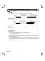
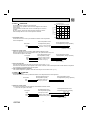
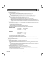
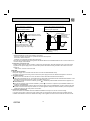
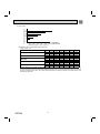
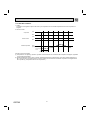
SPLIT-TYPE AIR CONDITIONERS
No. OBT49
SERVICE TECHNICAL GUIDE
Models
MSZ-HE09NA
MSZ-HE12NA
MSZ-HE15NA
MSZ-HE18NA
MSZ-HE24NA
MUZ-HE09NA
MUZ-HE12NA
MUZ-HE15NA
MUZ-HE18NA
MUZ-HE24NA
CONTENTS
1. MSZ MICROPROCESSOR CONTROL················ 3
CONFIDENTIAL
(FOR INTERNAL USE ONLY)
1. MSZ MICROPROCESSOR CONTROL ················································································································· 3
Indoor unit models
Outdoor unit models
MSZ-HE09NA
MSZ-HE12NA
MSZ-HE15NA
MSZ-HE18NA
MSZ-HE24NA
MUZ-HE09NA
MUZ-HE12NA
MUZ-HE15NA
MUZ-HE18NA
MUZ-HE24NA
1-1. COOL OPERATION ······································································································································· 3
1-2. DRY OPERATION ·········································································································································· 4
1-3. HEAT OPERATION ········································································································································ 4
1-4. AUTO CHANGE OVER ··· AUTO MODE OPERATION················································································· 7
1-5. OUTDOOR FAN MOTOR CONTROL ············································································································ 7
1-6. AUTO VANE OPERATION ····························································································································· 7
1-7. INVERTER SYSTEM CONTROL ··················································································································· 8
1-8. OPERATIONAL FREQUENCY CONTROL OF OUTDOOR UNIT ······························································ 12
1-9. EXPANSION VALVE CONTROL (LEV CONTROL) ···················································································· 13
1-10. PRE-HEAT CONTROL ································································································································· 15
OBT49
2
2
MSZ MICROPROCESSOR CONTROL
1-1. COOL (
) OPERATION
1. Thermostat control
Thermostat turns ON or OFF by the difference between room temperature and set temperature.
Thermostat
ON
OFF
Room temperature minus
set temperature (Initial)
Room temperature minus
set temperature (During operation)
-1.35°F (-0.75°C) or more
less than -1.8°F (-1°C)
-2.25°F
-1.35°F
(-1.25°C) (-0.75°C)
2. Indoor fan speed control
Indoor fan operates continuously at the set speed by FAN SPEED CONTROL button regardless of the thermostat's OFFON.
In AUTO the fan speed is as follows.
Fan speed
High
Med.
Low
Room temperature minus
set temperature (Initial)
3.15°F(1.75°C) or more
between 1.8 and 3.15°F
less than 1.8°F(1°C)
Room temperature minus
set temperature (During operation)
1.8°F
(1°C)
3.15°F
(1.75°C)
5.4°F
(3°C)
3. Coil frost prevention
The compressor operational frequency is controlled to prevent the temperature of indoor heat exchanger from falling excessively.
The compressor is turned OFF for 5 minutes when the temperature of indoor coil thermistor continues 37°F (3°C) or less for
5 minutes or more.
The indoor fan maintains the actual speed of the moment.
4. Low outside temperature operation
If the outside temperature falls to 64°F (18°C) or less during operation in COOL mode, the unit will switch to the low outside
temperature operation mode.
<Operation>
(1) Outdoor fan control
The outdoor fan rotational speed slows down to maintain sufficient cooling capacity.
NOTE: Even when the unit is in the "thermostat-off" status under the low outside temperature operation mode, the outdoor fan rotation does not stop.
(2) Dew drop prevention
When the ambient temperature thermistor reads 14°F (-10°C) or less (the set temperature is different depending on the
models), as coil frost or dew drop from indoor unit may occur, the compressor turns OFF with the outdoor fan OFF for
prevention of them.
(3) Outdoor temperature detecting control
To detect the exact outdoor temperature in this mode, the compressor turns OFF but the outdoor fan stays ON for 3
minutes once 1 hour. If the outdoor temperature rises over about 64°F (18°C), the unit goes back to the normal COOL
mode. If the outside temperature stays below about 64°F (18°C), the unit continues to run in the low outside temperature
operation mode.
Other protections work as well as in the normal COOL mode.
OBT49
3
) OPERATION
Set temperature is as shown on the right chart.
The system for dry operation uses the same refrigerant circuit as the
cooling circuit.
The compressor and the indoor fan are controlled by the room temperature.
By such controls, indoor flow amounts will be reduced in order to
lower humidity without much room temperature decrease.
1. Thermostat control
Thermostat turns ON or OFF by the difference between room temperature
and set temperature.
Thermostat
ON
OFF
95(35)
Set temperature [°F(°C)]
1-2. DRY (
Set temperature and
initial room temperature in dry mode
86(30)
77(25)
68(20)
59(15)
50(10)
50
(10)
Room temperature minus
set temperature (Initial)
59
68
77
86
95
(15)
(20)
(25)
(30) (35)
Initial room temperature [°F(°C)]
Room temperature minus
set temperature (During operation)
-3.15°F (-1.75°C) or more
less than -3.6°F (-2°C)
2. Indoor fan speed control
Indoor fan operates at the set speed by FAN SPEED CONTROL button.
When the thermostat turns OFF (compressor OFF), fan speed becomes Very Low.
In AUTO the fan speed is as follows.
Room temperature minus
Fan speed
set temperature (Initial)
High
3.15°F(1.75°C) or more
Med.
between 1.8 and 3.15°F
Low
less than 1.8°F(1°C)
-4.05°F
-3.15°F
(-2.25°C) (-1.75°C)
Room temperature minus
set temperature (During operation)
1.8°F
(1°C)
4.5°F
(2.5°C)
3.15°F
(1.75°C)
3. Coil frost prevention
Coil frost prevention works the same way as that in COOL mode. (1-1.3.)
The indoor fan maintains the actual speed of the moment. However, when coil frost prevention works while the compressor
is not operating, its speed becomes the set speed.
4. Low outside temperature operation
Low outside temperature operation works the same way as that in COOL mode. (1-1.4.)
1-3. HEAT (
) OPERATION
1. Thermostat control
Thermostat turns ON or OFF by difference between room temperature and set temperature.
Thermostat
ON
OFF
Room temperature minus
set temperature (Initial)
less than 1.8°F(1°C)
1.8°F(1°C) or more
2. Indoor fan speed control
(1) Indoor fan operates at the set speed by FAN SPEED CONTROL button.
In Auto the fan speed is as follows.
Set temperature minus
Fan speed
room temperature (Initial)
High
Med.
Low
OBT49
3.6°F(2°C) or more
Between 0.45 and 3.6°F
Less than 0.45°F(0.25°C)
4
Room temperature minus
set temperature (During operation)
1.35°F 1.8°F
(0.75°C) (1°C)
Set temperature minus room
temperature (During operation)
3.6°F
(2°C)
0.45°F
3.15°F
(0.25°C) (1.75°C)
7.2°F
(4°C)
(2) Cold air prevention control
When the compressor is not operating,
( ) if the temperature of room temperature thermistor is less than 66°F (19°C), the fan stops.
( ) if the temperature of room temperature thermistor is 66°F (19°C) or more and
( ) if the temperature of indoor coil thermistor is less than 32°F (0°C), the fan stops.
( ) if the temperature of indoor coil thermistor is 32°F (0°C) or more, the fan operates at Very Low.
When the compressor is operating,
( ) if the temperature of indoor coil thermistor is 104°F (40°C) or more, the fan operates at set speed.
( ) if the temperature of indoor coil thermistor is less than 104°F (40°C) and
( ) if heating operation starts after defrosting, the fan stops.
( ) if the temperature of room temperature thermistor is 66°F (19°C) or less, the fan stops.
( ) if the temperature of room temperature thermistor is more than 66°F (19°C), the fan operates at Very Low.
NOTE: When 3 minutes (MSZ-HE09/12/18NA)/ 4 minutes (MSZ-HE24NA) have passed since the compressor started
operation, this control is released regardless of the temperature of room temperature thermistor and indoor coil
thermistor.
(3) Warm air control
When the following any condition of (a. ~ c.) and the condition of are satisfied at the same time, warm air control
works.
a.) Fan speed is used in MANUAL.
b.) When cold air prevention has been released.
c.) When defrosting has been finished.
When the temperature of indoor coil thermistor is less than 104°F (40°C).
When warm air control works, the fan speed changes as follows to blow out warm air gradually.
Gradation of fan speed in initial
MSZ-HE09/12/15/18NA
<Time condition>
<Indoor fan speed>
Less than 2 minutes------------ Low
2 to 4 minutes-------------------- Med.
More than 4 minutes ----------- High
MSZ-HE24NA
<Time condition>
<Indoor fan speed>
Less than 4 minutes------------ Low
4 to 8 minutes-------------------- Med.
More than 8 minutes ----------- High
The upper limit of the fan speed in MANUAL is the set speed.
When the temperature of indoor coil thermistor has been 104°F (40°C) or more, or when the set speed has been
changed, this control is released and the fan speed is the set speed.
3. Overload starting
When the room temperature thermistor reads 64°F (18°C) or more, the compressor runs with its maximum frequency regulated for 10 minutes after the start-up.
4. Defrosting
(1) Starting conditions of defrosting
When the following conditions a) ~ c) are satisfied, the defrosting starts.
a) The defrost thermistor reads about 30.2°F (-1°C) or less.
b) The cumulative operation time of the compressor has reached any of the set values (defrost interval: 40-150 minutes).
c) More than 5 minutes have passed since the start-up of the compressor.
The defrost interval is decided by the previous defrosting time. The next defrost interval extends or shortens 0-20
minutes compared with the previous defrost interval.
(2) Releasing conditions of defrosting
Defrosting is released when any one of the following conditions is satisfied:
a) The defrost thermistor continues to read "Defrost finish temperature" for 30 seconds.
Refer to "CHANGE IN DEFROST SETTING of SERVICE FUNCTIONS in OUTDOOR UNIT SERVICE MANUAL".
b) Defrosting time has exceeded 10 minutes.
c) Any other mode than HEAT mode is set during defrosting.
OBT49
5
Time chart of defrosting in HEAT mode (reverse type)
<Indoor unit>
Horizontal vane
horizontal
set position
Indoor fan
horizontal (temperature of indoor coil thermistor < 102 °F)
(39°C)
set speed Very Low (temperature of indoor coil thermistor > 64 °F)
(18°C)
OFF
set position
set speed
30
seconds
<Outdoor unit>
Maximum frequency
Compressor normal
OFF
40
30
seconds seconds
OFF
40
seconds
5 seconds
ON
30
seconds
5 seconds
ON
Outdoor fan
OFF
R.V. coil
(21S4)
OBT49
ON (HEAT)
ON (HEAT)
OFF (COOL)
6
1-4. AUTO CHANGE OVER ··· AUTO MODE OPERATION
Once desired temperature is set, unit operation is switched automatically between COOL and HEAT operation.
1. Mode selection
(1) Initial mode
At first indoor unit operates only indoor fan with outdoor unit OFF for 3 minutes to detect present room temperature.
Following the conditions below, operation mode is selected.
If the room temperature thermistor reads more than set temperature, COOL mode is selected.
If the room temperature thermistor reads set temperature or less, HEAT mode is selected.
(2) Mode change
In case of the following conditions, the operation mode is changed.
COOL mode changes to HEAT mode when 15 minutes have passed with the room temperature 2 - 4°F (1 - 2°C)
below the set temperature.
HEAT mode changes to COOL mode when 15 minutes have passed with the room temperature 2 - 4°F (1 - 2°C)
above the set temperature.
In the other cases than the above conditions, the present operation mode is continued.
NOTE1: Mode selection is performed when multi standby (refer to NOTE2) is released and the unit starts operation with
ON-timer.
NOTE2: When two or more indoor units are operating simultaneously, the indoor unit, which is operating in AUTO (
),
might not be able to change over the operating mode (COOL ↔ HEAT) and becomes the standby state.
(3) Indoor fan control/ Vane control
As the indoor fan speed and the horizontal vane position depend on the selected operation mode, when the operation
mode changes over, they change to the exclusive ones.
1-5. OUTDOOR FAN MOTOR CONTROL
Fan speed is switched according to the compressor frequency.
Fan speed
<Relation between compressor frequency and fan speed>
Down
Up
Compressor frequency (Hz)
High
Applied model
Down
Up
MUZ-HE09
39
54
Low
MUZ-HE12/15/18
33
44
Min. Compressor frequency Max.
MUZ-HE24
33
43
1-6. AUTO VANE OPERATION
1. Horizontal vane
(1) Cold air prevention in HEAT operation
When any of the following conditions occur in HEAT operation, the vane angle changes to Horizontal position automatically to prevent cold air blowing on users.
Compressor is not operating.
Defrosting is performed.
Indoor coil thermistor temperature does not exceed 102°F (39°C) within about 3 minutes after compressor starts.
NOTE: When 2 or more indoor units are operated with multi outdoor unit, even if any indoor unit turns thermostat OFF,
this control does not work in the indoor unit.
(2) ECONO COOL (
) operation (ECONOmical operation)
When ECONO COOL button is pressed in COOL mode, set temperature is automatically set 3.6°F (2°C) higher than that
in COOL mode.
Also the horizontal vane swings in various cycle according to the temperature of indoor heat exchanger (indoor coil
thermistor).
SWING operation makes you feel cooler than set temperature. So, even though the set temperature is higher than that
in COOL mode, the air conditioner can keep comfort. As a result, energy can be saved.
To cancel this operation, select a different mode or press one of the following buttons in ECONO COOL operation:
ECONO COOL or VANE CONTROL button.
OBT49
7
<SWING operation>
In swing operation of ECONO COOL operation mode, the initial air flow direction is adjusted to “Horizontal”.
According to the temperature of indoor coil thermistor RT12 at starting of this operation, next downward blow time is
decided. Then when the downward blow has been finished, next horizontal blow time is decided.
For initial 10 minutes the swing operation is performed in table G~H for quick cooling.
Also, after 10 minutes when the difference of set temperature and room temperature is more than 3.6°F (2°C), the
swing operation is performed in table D~H for more cooling.
The air conditioner repeats the swing operation in various cycle as follows.
Temperature of indoor
coil thermistor (°F/°C)
59/15 or less
59/15 to 63/17
63/17 to 64/18
64/18 to 68/20
68/20 to 70/21
70/21 to 72/22
72/22 to 75/24
more than 75/24
A
B
C
D
E
F
G
H
Downward blow time Horizontal blow time
(second)
(second)
2
23
5
20
8
17
11
14
14
11
17
8
20
5
23
2
1-7. INVERTER SYSTEM CONTROL
1-7-1. Inverter main power supply circuit
MUZ-HE09/12/15/18
REACTOR
POWER
SUPPLY
NOISE
FILTER
CIRCUIT
RESISTOR
DIODE
MODULE1
+
~
~
-
+ SMOOTHING
CAPACITOR
P
V
N
RELAY
CURRENT
TRANSFORMER
U
U
W
INVERTER
MODULE
~
+
~
DIODE
MODULE2
V
MS
3~
W
COMPRESSOR
SWITCHING
POWER
TRANSISTOR
BOOSTER CHOPPER CIRCUIT
Function of main parts
NAME
FUNCTION
INVERTER MODULE
It supplies 3-phase AC power to compressor.
SMOOTHING CAPACITOR
It stabilizes the DC voltage and supplies it to INVERTER MODULE.
CURRENT TRANSFORMER
It measures the current of the compressor motor.
DIODE MODULE 1
It converts the AC voltage to DC voltage.
RESISTOR
It absorbs the rush current not to run into the main power supply circuit when
the power is turned ON.
RELAY
It keeps the RESISTOR, which restricts rush current, short-circuited while
the compressor is operating.
BOOSTER
CHOPPER
CIRCUIT
DIODE MODULE 2
SWITCHING POWER TRANSISTOR It improves power factor.
It controls the bus-bar voltage.
REACTOR
OBT49
8
MUZ-HE24
CURRENT
TRANSFORMER
U
U
REACTOR
NOISE
FILTER
CIRCUIT
POWER
SUPPLY
RESISTOR
+ SMOOTHING
CAPACITOR
P
V
N
RELAY
POWER FACTOR
CORRECTION
MODULE
W
INVERTER
MODULE
V
MS
3~
W
COMPRESSOR
Function of main parts
NAME
FUNCTION
INVERTER MODULE
It supplies 3-phase AC power to compressor.
SMOOTHING CAPACITOR
It stabilizes the DC voltage and supplies it to INVERTER MODULE.
CURRENT TRANSFORMER
It measures the current of the compressor motor.
REACTOR
It rectifies AC, controls its voltage and improves the power factor of power supply.
POWER FACTOR CORRECTION MODULE
RESISTOR
RELAY
It absorbs the rush current not to run into the main power supply circuit when the
power is turned ON.
It keeps the RESISTOR, which restricts rush current, short-circuited while the
compressor is operating.
1-7-2. Outline of main power supply circuit
MUZ-HE09/12/15/18
1. At the start of operation
Main power supply circuit is formed when RELAY is turned ON at COMPRESSOR startup.
To prevent rush current from running into the circuit when power supply is turned ON,
RESISTOR is placed in sub circuit.
2. At normal operation
When AC runs into POWER P.C. board, its external noise is eliminated in NOISE FILTER CIRCUIT.
After noise is eliminated from AC, it is rectified to DC by DIODE MODULE 1.
DC voltage, to which AC has been rectified by process , is stabilized by SMOOTHING CAPACITOR and supplied to INVERTER MODULE.
DC voltage, which has been stabilized in process , is converted to 3-phase AC by INVERTER MODULE and supplied to
COMPRESSOR.
CURRENT TRANSFORMER, which is placed in the power supply circuit to COMPRESSOR, is used to measure the value
of phase current and locate the polar direction of rotor with algorithm. PWM (Pulse width modulation) controls impressed
voltage and frequency with those pieces of information.
3. Purpose of PAM adoption
PAM (Pulse Amplitude Modulation) has been adopted for the efficiency improvement and the adaptation to IEC harmonic current emission standard
Outline of simple partial switching method
In conventional inverter models, DIODE MODULE rectifies AC voltage to DC voltage, SMOOTHING CAPACITOR makes its
DC waveform smooth, and INVERTER MODULE converts its DC voltage to imitated AC voltage again in order to drive the
compressor motor.
However, it has been difficult to meet IEC harmonic current emission standard by above circuit because harmonic gets
generated in the input current waveform and power factor gets down. The simple partial switching method with PAM, which
has been adopted this time, places and utilizes BOOSTER CHOPPER CIRCUIT before rectifying AC voltage in the general
passive-method converter circuit. As harmonic gets suppressed and the peak of waveform gets lower by adding BOOSTER
CHOPPER CIRCUIT as mentioned above and by synchronizing the timing of switching with the zero-cross point of waveform,
the input current waveform can be improved and the requirement of IEC harmonic current emission standard can be satisfied.
Since the switching synchronized with the zero cross point, this simple partial switching method has the feature of lower energy loss compared to active filter method. In addition, output and efficiency is enhanced by combining with vector-controlled
inverter in order to boost the voltage of power supplied to INVERTER MODULE.
OBT49
9
Input current waveform without PAM
Input current waveform with PAM
Due to the time of no electricity;
• Power factor gets worse.
• Harmonic gets increased.
Input voltage
Input current
Owing to the increase of energized time;
• Power factor gets better.
• Harmonic gets suppressed.
Release of energy stored in L.
Peak gets down.
Energized time is
extended by
optimization
of L inductance.
Energized time is short in
case L inductance is small.
No electricity runs into
diode module because the
voltage at both sides of smoothing
capacitor is higher than input voltage.
Compulsory energizing
by switching.
4. Inverter module
INVERTER MODULE consists of the following components
· IGBT (x6): Converts DC waveform to 3-phase AC waveform and outputs it.
· Drive Circuit: Drives transistors.
· Protection circuit: Protects transistors from overcurrent.
Since the above components are all integrated in INVERTER MODULE, INVERTER MODULE has a merit to make the control circuit simplify and miniaturize.
5. Elimination of electrical noise
NOISE FILTER CIRCUIT, which is formed by *CMC COILS and capacitors, eliminates electrical noise of AC power that is
supplied to main power supply circuit. This circuit also prevents the electrical noise generated in the inverter circuit from
leaking out.
*CMC COILS: Common mode choke coils
MUZ-HE24
1. At the start of operation
Main power supply circuit is formed when RELAY is turned ON at COMPRESSOR startup.
To prevent rush current from running into the circuit when power supply is turned ON, RESISTOR is placed in sub circuit.
2. At normal operation
When AC runs into noise filter P.C. board, its external noise is eliminated in NOISE FILTER CIRCUIT.
After noise is eliminated from AC, it is rectified to DC by REACTOR and POWER FACTOR CORRECTION MODULE. If the
operating frequency becomes 25 Hz or more, DC voltage rises to 370 V.
DC voltage, to which has AC been rectified by process , is stabilized by SMOOTHING CAPACITOR and supplied to INVERTER MODULE.
The DC (Bus voltage), which has been stabilized in process , is converted to 3-phase AC by INVERTER MODULE and
supplied to COMPRESSOR.
CURRENT TRANSFORMER, which is placed in the power supply circuit to COMPRESSOR, is used to measure the value
of phase current and locate the polar direction of rotor with algorithm. PWM (Pulse width modulation) controls impressed
voltage and frequency with those pieces of information.
3. Power factor improvement
Booster coil reactor and POWER FACTOR CORRECTION MODULE rectify AC to DC and control its voltage.
In the motor drive system of sine wave control, power factor can be improved by reducing harmonics. POWER FACTOR
CORRECTION MODULE and reactor stabilize the voltage of DC supplied to inverter circuit and make its waveform smooth.
OBT49
10
4. Inverter module
INVERTER MODULE consists of the following components.
· IGBT (x6): Converts DC waveform to 3-phase AC waveform and outputs it.
· Drive Circuit: Drives transistors.
· Protection circuit: Protects transistors from over current.
Since the above components are all integrated in INVERTER MODULE, INVERTER MODULE has a merit to make the control circuit simplified and miniaturized.
5. Elimination of electrical noise
NOISE FILTER CIRCUIT, which is formed by *CMC COILS, *NMC COILS and capacitors, eliminates electrical noise of AC
power that is supplied to main power supply circuit. This circuit also prevents the electrical noise generated in the inverter
circuit from leaking out.
*CMC COILS: Common mode choke coils
*NMC COILS: Normal mode choke coils
1-7-3. Sine wave control
In these air conditioners, compressor equips brushless DC motor which does not have Hall element.
In short, the motor is sensorless. However, it is necessary to locate the polar direction of rotor in order to drive brushless DC motor efficiently. The general detection method of the polar direction for such a DC motor is to locate it from the voltage induced by
unenergized stator.
Therefore, it is necessary to have a certain period of time in which the stator is being unenergized for the rotor position detection
when the voltage of supplied power is impressed.
So the motor has been driven by square wave control (the conventional motor drive system) which energizes the motor only
when the range of electrical angle is within 120° because it is forced to be unenergized within 30° at start & end of one heap in
one waveform cycle (180°) when the voltage is impressed.
However, torque pulsation occurs at rotation in this method when the current-carrying phases are switched over to other phases
in sequence. Therefore, sine wave control system is adopted for these air conditioners because it can make the phase-to-phase
current waveform smoother (sine wave) in order to drive the motor more efficiently and smoothly.
1-7-4. Characteristics of sine wave control in case of brushless DC motor
● Although ordinary 3-phase induction motor requires energy to excite the magnetic field of rotor, brushless DC motor does not
need it. So, higher efficiency and torque are provided.
● This control provides the most efficient waveform corresponding to the rotational speed of compressor motor.
● The rotation can be set to higher compared to the conventional motor drive system. So, the time in which air conditioner can
be operated with less energy is longer than conventional models. This can save annual electric consumption.
● Compared to square wave control, the torque pulsation is reduced at rotation so that the motor operates more quietly.
● Since the response and efficiency of motor are enhanced in sine wave control, finer adjustment can be provided.
DC Motor
AC Motor
Rotor
Permanent magnet is embedded.
It is excited by magnetic field of stator.
Rotor Position Signal
Necessary
Unnecessary
In brushless DC motor, permanent magnet is embedded in the rotor. Therefore, it does not require energy to excite the rotor
like AC motor does. However, it is necessary to control the frequency of 3-phase AC current supplied to the stator according to the polar direction of magnet embedded in the rotor so as to drive the motor efficiently. Controlling 3-phase AC current
frequency also means controlling the timing to switch the polarity of stator. Therefore, the polar direction of rotor needs to be
detected.
1-7-5. Control Method of Rotational speed
Sine wave control makes the current transformers conduct real time detection of the value of the current running into the motor, locates the rotor position from the detected value, and decides if voltage should be impressed and if frequency should be
changed.
Compared to the conventional control and rotor position detection method, sine wave control can provide finer adjustment of the
voltage of supplied power. The value of the current running into the motor is determined by each motor characteristic.
OBT49
11
1-8. OPERATIONAL FREQUENCY CONTROL OF OUTDOOR UNIT
1. Outline
The operational frequency is as following:
First, the target operational frequency is set based on the difference between the room temperature and the set temperature.
Second, the target operational frequency is regulated by discharge temperature protection, high pressure protection, electric
current protection and overload protection and also by the maximum/minimum frequency.
2. Maximum/minimum frequency in each operation mode.
Applied model
MUZ-HE09
MUZ-HE12
MUZ-HE15
MUZ-HE18
MUZ-HE24
Operational frequency (Hz)
COOL
HEAT
DRY
Minimum Maximum Minimum Maximum Minimum Maximum
28
93
30
105
28
48
20
98
30
98
30
55
15
90
15
102
15
54
15
98
15
105
15
83
26
120
26
124
26
120
The operation frequency in COOL mode is restricted by the upper limit frequency after 1 hour or 0.5 ~ 1 hour as shown
below for dew prevention.
It is rated frequency or less.
Maximum
frequency
Upper limit
frequency
1 hour
or
0.5~1 hour
Rated frequency or less
Time
OBT49
12
1-9. EXPANSION VALVE CONTROL (LEV CONTROL)
Standard specification
(1) Outline of LEV control
The LEV basic control is comprised of setting LEV opening degree to the standard opening degrees set for each operational frequency of the compressor. However, when any change in indoor/outdoor temperatures or other factors cause
air conditioning load fluctuation, the LEV control also works to correct LEV opening degree based on discharge temperature (Shell temperature) of the compressor, developing the unit's performance.
Control range
Minimum: 54 pulses
Maximum: 500 pulses
Actuating speed
Open: 40 pulses/second
Close: 90 pulses/second
Opening degree adjustment
LEV opening degree is always adjusted in opening direction. (When reducing
the opening degree, LEV is once over-closed, and then adjusted to the proper
degree by opening.
Unit OFF
LEV remains at maximum opening degree (reaches maximum opening
degree approximate in 15 minutes after compressor stops)
LEV is positioned. (First full-closed at zero pulses and then positioned.)
General operation
Remote controller ON
During 1 to 15 minutes after compressor
starts
More than about 15 minutes have
passed since compressor start-up
Thermostat OFF
Thermostat ON
Defrosting in HEAT mode
LEV is fixed to standard opening degree according to operational frequency
of compressor.
LEV opening degree is corrected to get target discharge temperature of compressor.
(For lower discharge temperature than target temperature, LEV is corrected
in closing direction.)
(For higher discharge temperature than target temperature, LEV is corrected
in opening direction.)
It may take more than 30 minutes to reach target temperature, depending
on operating conditions.
LEV is adjusted to exclusive opening degree for thermostat OFF.
LEV is controlled in the same way as that after the compressor has started
up.
LEV is adjusted to open 500 pulses
(2) Time chart
Air conditioner OFF
(thermostat off)
Air conditioner ON
LEV opening degree
Positioning
Standard
opening
degree
Opening degree is
corrected according
to discharge
temperature.
(Refer to (3))
Operational frequency
of the compressor
About 15 minutes
OBT49
Commanded
to open
Time
ON
OFF Time
13
Target discharge temperature
(3) Control data
F
E
D
C
B
A
23
30
38
50
53
70
69
90
84
110
99 (Hz) (MUZ-HE24)
130 (Hz) (Other models)
Operational frequency of the compressor
(a) Reference value of target discharge temperature
COOL / HEAT °F/°C
Applied model
MUZ-HE09
MUZ-HE12
MUZ-HE15
MUZ-HE18
MUZ-HE24
COOL
HEAT
COOL
HEAT
COOL
HEAT
COOL
HEAT
COOL
HEAT
A
126/52
109/43
127/53
109/43
120/49
109/43
135/57
140/60
131/55
115/46
B
136/58
122/50
140/60
124/51
131/55
124/51
140/60
149/65
142/61
133/56
C
149/65
131/55
147/64
138/59
147/64
138/59
144/62
158/70
151/66
151/66
D
153/67
138/59
153/67
156/69
153/67
156/69
153/67
167/75
162/72
167/75
E
158/70
149/65
162/72
167/75
162/72
167/75
165/74
167/75
171/77
181/83
F
160/71
156/69
169/76
176/80
169/76
176/80
178/81
167/75
178/81
187/86
In COOL operation, the indoor coil thermistors (main and sub) sense temperature ununiformity (super heat) at
the heat exchanger, and when temperature difference develops, the indoor coil thermistors adjust LEV opening
degree to get approximate 18°F (10°C) lower temperature than the target temperature in the table above, thus
diminishing super heat.
OBT49
14
1-10. PRE-HEAT CONTROL
1. Outline
Compressor is energized to improve the start-up of compressor at a low outside temperature even when compressor is
stopped.
2. Pre-heat control
Compressor
ON
OFF
ON
Pre-heat control
OFF
Outside temperature
68°F
(20°C)
30 minutes 1 hour
Pre-heat control ON condition
(1) Compressor is not operating. (However, pre-heat control is still OFF for 30 minutes after compressor is stopped, regardless
of the outside temperature.)
(2) Outside temperature is 68°F (20°C) or below. Outside temperature is monitored hourly, and when outside temperature is
68°F (20°C) or below, pre-heat control is turned ON. When pre-heat control is turned ON, compressor is energized about
50 W (40-60 W). (Compressor and fan are not operated.)
OBT49
15
HEAD OFFICE: TOKYO BLDG.,2-7-3, MARUNOUCHI, CHIYODA-KU, TOKYO 100-8310, JAPAN
© Copyright 2014 MITSUBISHI ELECTRIC CORPORATION
Distributed in Feb. 2014. No. OBT49
Made in Japan
New publication, effective Feb. 2014
Specifications are subject to change without notice.