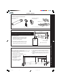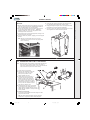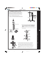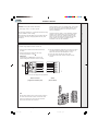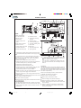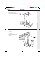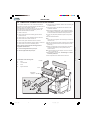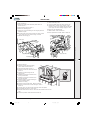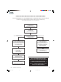
1
back
installation and
servicing
isar
(V3 Flue System)
Your Ideal installation and servicing guide
For details of document amendments, refer to page 3
HE24, HE30, HE35
For users guide see reverse of book
When replacing any part on this appliance, use only spare parts that you can be
assured conform to the safety and performance specification that we require. Do not
use reconditioned or copy parts that have not been clearly authorised by Ideal Boilers.
February 2008 UIN 203319 A03
For the very latest copy of literature for specification purposes please visit our website
www.idealboilers.com where you will be able to download the relevant information in pdf format.
203319-3.pmd
1
27/03/2008, 08:14
back
2
203319-3.pmd
isar - Installation and Servicing
2
27/03/2008, 08:14
back
DOCUMENT AMENDMENTS
Relevant Installation changes implemented in this book from Mod Level ..................... A02 to A03 (March 08)
•
Page 14, Frame 9 - Unpacking
Change to Pack A contents with regard to Wall Mounting Template.
•
Page 15, Frame 10 - Packing Removal
Wall Mounting Template change.
•
Page 17, Frame 14 - Wall Mounting Template
Change to procedure for mounting boiler onto a wall.
Ideal Stelrad Group reserve the right to vary specification without notice
isar - Installation and Servicing
203319-3.pmd
3
3
27/03/2008, 08:14
back
GENERAL
Table 1 - General Data
isar
Gas supply
Gas Supply Connection
Injector Size
Inlet Connection
Domestic Hot Water
Outlet Connection
Domestic Hot Water
Flow Connection
Central Heating
Return Connection
Central Heating
Flue Terminal Diameter
mm (in)
Average Flue Temp-Mass Flow Rate
(DHW)
Maximum Working Pressure (Sealed Systems)
bar (lb/in2)
Maximum Domestic Hot Water Inlet Pressure
bar (lb/in2)
Minimum Domestic Hot Water Inlet Pressure
bar (lb/in2)
Electrical Supply
Power Consumption
Fuse Rating
Water content
Central Heating
litre (gal)
Domestic Hot Water
Packaged Weight
kg (lb)
Maximum Installation Weight
kg (lb)
Boiler Casing Size
Height
mm (in)
Width
mm (in)
Depth
mm (in)
Table 2 - Performance Data - Central Heating
Boiler Input :
Boiler Input ‘Q’
Nett CV
kW
(Btu/h)
Gross CV
kW
(Btu/h)
Gas Consumption
l/s
(ft3/h)
kW
70oC Mean Water temp.
(Btu/h)
Condensing
kW
40 C Mean Water temp.
(Btu/h)
o
Seasonal efficiency*
(SEDBUK)
Max.
Min.
24.4
9.1
Maximum DHW Input :
Nett CV
(83 300)
(31 000)
27.1
10.1
(92 500)
(34 400)
0.70
0.26
(89.0)
(33.1)
23.4
8.8
(80 000)
(30 000)
25.1
9.6
(85 700)
(32 800)
Band A [90.1]%
NOx Classification
HE30
HE35
2H - G20 - 20mbar
Rc 1/2 (1/2” BSP female)
Stereomatic 5.6mm dia.
5.7mm dia
15mm copper compression
15mm copper compression
22mm copper compression
22mm copper compression
100 (4)
o
74 C - 12 g/s
82 oC-14g/s
66 oC-10g/s
2.5 (36.3)
10.0 (145)
0.5 (7)
230 V ~ 50 Hz.
148 W
148 W
152 W
External : 3A Internal : T3.15A L250 V
2.0 (0.44)
0.5 (0.11)
52 (115)
52 (115)
53 (117)
42.5 (94)
43 (95)
43.5 ( 96)
687 (27)
390 (15 3/8)
278 (11)
Table 3 - Performance Data - Domestic Hot Water
kW
HE24
HE30
HE35
24.3
30.2
36.0
(Btu/h) (82 900) (103 000) (122 800)
Gross CV
kW
27.0
33.5
39.9
(Btu/h) (92 100) (114 400) (136 200)
Gas Consumption
l/s
(ft3/h)
Boiler Output :
Non Condensing
HE24
Maximum
DHW Output
0.7
0.87
1.03
(89.0)
(110)
(131)
kW
23.4
29.3
35.2
(Btu/h) (80 000) (100 000) (120 000)
DHW Flow Rate
at 35°C temp. rise.
l/min
(gpm)
9.6
(2.1)
12.0
2.6
14.4
(3.2)
DHW Specific Rate
l/min
(gpm)
11.2
(2.5)
14.0
(3.1)
16.8
(3.7)
Class 5
* The value is used in the UK Government's Standard Assessment Procedure (SAP) for energy rating of dwellings. The test data from which
it has been calculated have been certified by a notified body.
Note. Gas consumption is calculated using a
calorific value of 38.7 MJ/m3 (1038 Btu/ft3) gross
or 34.9 MJ/m3 (935 Btu/ft3) nett
To obtain the gas consumption at a different
calorific value:
a. For l/s- divide the gross heat input (kW) by
the gross C.V. of the gas (MJ/m3)
3
b. For ft /h - divide the gross heat input (Btu/h)
by the gross C.V. of the gas (Btu/ft3)
Key to symbols
GB =
United Kingdom
IE = Ireland
(Countries of destination)
PMS = Maximum operating pressure of water
C13 C33 C53 = A room sealed appliance designed for connection via ducts to a
horizontal or vertical terminal, which admits fresh air to the burner
and discharges the products of combustion to the outside through
orifices which, in this case, are concentric. The fan is up stream
of the combustion chamber.
I2H
= An appliance designed for use on 2nd Family gas, Group H only.
CAUTION. To avoid the possibility of injury during the installation, servicing or cleaning of
this appliance care should be taken when handling edges of sheet steel components
4
203319-3.pmd
isar - Installation and Servicing
4
27/03/2008, 08:14
back
GENERAL
CONTENTS
isar
Air Supply ....................................................................... 8
Natural Gas only
Boiler size
G.C. Appliance No.
(Benchmark No.)
PI No.
47 348 31
47 348 30
47 348 29
87 BP 34
87 BP 34
87 BP 34
HE24
HE30
HE35
Benchmark Commissioning Checklist ..................... 66
Boiler Clearances ......................................................... 9
Boiler Exploded Diagram ............................................ 13
Condensate Drain ........................................... 10, 21-22
Electrical Connections ............................................... 31
Electrical Supply ......................................................... 10
Extension Ducts - Fitting ............................................. 19
Destination Country:
GB, IE
Fault Finding ........................................................... 56-60
Flow Wiring Diagram .................................................. 34
Flue Fitting .................................................................... 18
Flue Installation ............................................................. 8
Gas Safety Regulations ................................................ 7
Gas Supply ..................................................................... 8
Installation ............................................................. 12-37
Mandatory Requirements ....................................... 7-10
Pump .......................................................................... 53
Safe Handling ................................................................ 6
Servicing ................................................................ 38-55
Short List of Parts ....................................................... 61
Thermostatic Radiator Valves ................................... 10
Water and Systems ........................................... 8,10-12
Water Connections ............................................... 28-29
Water Treatment ......................................................... 12
Wiring Diagrams ................................................... 32-34
For GB, to comply with Building Regulations Part L1 (Part 6 in Scotland) the boiler should be fitted in accordance with the
manufacturer's instructions. Self-certification that the boiler has been installed to comply with Building Regulations can be
demonstrated by completing and signing the Benchmark Commissioning Checklist.
BENCHMARK COMMISSIONING CHECKLIST DETAILS
Boiler
Page
Make and model ....................................................... 5
Appliance serial no. on data badge ...................... 13
SEDBUK No. % ......................................................... 4
Controls
Time and temperature control to heating ............. 32
Time and temperature control to hot water .......... 32
Heating zone valves .............................................. n/a
TRV's ...................................................................... 10
Auto bypass ........................................................... 10
Boiler interlock ....................................................... 10
For all boilers
Flushing to BS.7593 .............................................. 12
Inhibitor .................................................................. 12
Central heating mode
Heat input ................................................ to be calculated
Page
Burner operating pressure .................................... n/a
Central heating flow temp. ...... measure and record
Central heating return temp. ... measure and record
For combination boilers only
Scale reducer ......................................................... n/a
Hot water mode
Heat input .......................................... to be calculated
Max. operating burner pressure .............................. n/a
Max. operating water pressure ........... measure & record
Cold water inlet temp ..................... measure & record
Hot water outlet temp. .................... measure & record
Water flow rate at max. setting ............ measure & record
For condensing boilers only
Condensate drain .................................................. 21
For all boilers: complete, sign & hand over to customer
For assistance see Technical Helpline on the back page
NOTE TO THE INSTALLER: COMPLETE
THE BENCHMARK COMMISSIONING
CHECKLIST AND LEAVE THESE
INSTRUCTIONS WITH APPLIANCE
isar - Installation and Servicing
203319-3.pmd
5
5
27/03/2008, 08:14
back
GENERAL
1
Central Heating Circuit
Expansion
vessel
Fan
Burner
Automatic
air vent
Heat
exchanger
Gas valve
Sump
Plate heat
exchanger
Condensate
'S' trap
Pump
Diverter
valve
Safety
relief valve
CH Return
Discharg
pipe
Water
pressure
gauge
Domestic Hot Water Circuit
Expansion
vessel
Fan
With no demand for CH, the boiler fires only when DHW is drawn off, or
periodically for a few seconds without any DHW draw-off, in order to maintain
the DHW calorifier in a heated condition.
Burner
When there is a demand for CH, the heating system is supplied at the
selected temperature of between 30 oC and 82oC, until DHW is drawn off.
The full output from the boiler is then directed via the diverter valve to the
plate heat exchanger to supply a nominal DHW draw-off of
Automatic
air vent
Heat
exchanger
HE24 9.6 l/min at 35 oC temperature rise.
HE30 12 l/min at 35 oC temperature rise.
Refer also to Frame 1 - 'Boiler Water Circuit Diagrams'
The boiler features a comprehensive diagnostic system which gives detailed
information on the boiler status when operating, and performance of key
components to aid commissioning and fault finding.
SAFE HANDLING
Pump
Diverter
valve
Safety
relief valve
Water
pressure
gauge
Discharge pipe
At low DHW draw-off rate the maximum temperature is limited to 65 oC by the
modulating gas control.
Plate heat
exchanger
Condensate
'S' trap
DHW Cold in
The DHW draw off rate specified above is the nominal that the boiler flow
regulator will give. Due to system variations and seasonal temperature
fluctuations DHW flow rates/temperature rise will vary, requiring adjustment
at the draw off tap.
Gas valve
Sump
DHW Hot out
Condensate drain
Gas
HE35 14.4 l/min at 35 oC temperature rise.
nm8763
OPERATION
BOILER WATER
CIRCUIT DIAGRAMS
Condensate
drain
Gas
The isar range of boilers are wall mounted, full sequence, automatic spark
ignition, low water content, fanned flue, high efficiency, condensing,
combination gas boilers.
Note. Due to the high efficiency of the boiler a plume of water vapour will form
at the terminal during operation.
Central heating (CH) output is fully modulating with a range of 8.8 to 23.4kW
(30,000 to 80,000 Btu/h)
Instantaneous domestic hot water (DHW) output is also fully modulating with
a maximum of :
HE24 24.4kW (80,000 Btu/h)
HE30 29.3kW (100,000 Btu/h)
HE35 35.2kW (120,000 Btu/h)
The boiler is supplied fully assembled with DHW plate heat exchanger,
diverter valve, circulating pump, pressure gauge, safety valve and CH
expansion vessel.
Variable CH and DHW temperature controls are fitted on the user control and
the boiler features a DHW preheat facility.
The boiler casing is of white painted mild steel with the user controls
capable of being mounted remotely from the boiler if the option is required.
The boiler temperature controls are visible at the bottom RHS of the front
panel.
The heat exchanger is of cast aluminium.
The boiler is suitable for connection to fully pumped, sealed water systems
ONLY. Adequate arrangements for completely draining the system by
provision of drain cocks MUST be provided in the installation pipework.
Pipework from the boiler is routed downwards as standard, but may be
routed upwards behind the boiler using the stand-off frame (supplied in a
separate kit).
CH Flow
INTRODUCTION
This boiler may require 2 or more operatives to move it to its installation site,
remove it from its packaging base and during movement into its installation
location. Manoeuvring the boiler may include the use of a sack truck and
involve lifting, pushing and pulling.
During all manoeuvres and handling actions, every
attempt should be made to ensure the following
unless unavoidable and/or the weight is light.
• Keep back straight.
Caution should be exercised during these operations.
• Avoid twisting at the waist.
Operatives should be knowledgeable in handling techniques when
• Avoid upper body/top heavy bending.
performing these tasks and the following precautions should be considered:
• Always grip with the palm of the hand.
• Grip the boiler at the base.
• Use designated hand holds.
• Be physically capable.
• Keep load as close to the body as possible.
• Use PPE as appropriate, e.g. gloves, safety footwear.
• Always use assistance if required.
6
203319-3.pmd
isar - Installation and Servicing
6
27/03/2008, 08:14
back
GENERAL
OPTIONAL EXTRA KITS
BS. 6798
z Flue Extension Ducts. (1000mm long).
HE24-upto 6m
HE30-upto 6m
HE35-upto 3m
Installation of gas fired hot water boilers of rated
input not exceeding 70 kW.
BS. 6891
Low pressure installation pipes.
z Flue Finishing Kit.
The manufacturer’s notes must NOT be taken, in any way, as
overriding statutory obligations.
o
z 90 Elbow Kit (maximum per installation).
HE24-upto 4 elbows
HE30-upto 4 elbows
HE35-upto 2 elbows
o
z 45 Elbow Kit (maximum per installation).
HE24-upto 4 elbows
HE30-upto 4 elbows
HE35-upto 2 elbows
z Roof Flue Kit (to a maximum of 7.5m).
z Powered Vertical Flue Kit (5m primary and 17m secondary
is a typical maximum length. For alternative details refer to
Powered Vertical Instructions).
z
z
z
z
z
z
z
z
z
z
High Level Flue Outlet Kits
Flue Deflector Kit
Weather Collar
Twin Fluing Kits (up to a maximum of 60m combined total
flue and airducts)
Horizontal Flue Terminal 600mm long
Remote User Controls Kit
Boiler Stand-off Kit
Siphon Kit
Valve Cover Kit
Contensate Pump Kit
Health & Safety Document No. 635.
The Electricity at Work Regulations, 1989.
IMPORTANT. These appliances are CE certificated for safety
and performance. It is, therefore, important that no external
control devices, e.g. flue dampers, economisers etc., are
directly connected to these appliances unless covered by these
Installation and Servicing Instructions or as otherwise
recommended by Ideal Stelrad Group in writing. If in doubt
please enquire.
Any direct connection of a control device not approved by Ideal
Stelrad Group could invalidate the certification and the normal
appliance warranty. It could also infringe the Gas Safety
Regulations and the above regulations.
SAFE HANDLING OF SUBSTANCES
Care should be taken when handling the boiler insulation
panels, which can cause irritation to the skin. No asbestos,
mercury or CFCs are included in any part of the boiler or its
manufacture.
LOCATION OF BOILER
The boiler must be installed on a flat and vertical wall, capable
of adequately supporting the weight of the boiler and any
ancillary equipment.
The boiler may be fitted on a combustible wall and insulation
between the wall and the boiler is not necessary, unless
required by the local authority.
For electrical safety reasons there must be no access available
from the back of the boiler.
SAFETY
Current Gas Safety (installation and use) regulations or rules
in force:
The boiler must not be fitted outside.
The appliance is suitable only for installation in GB and IE and
should be installed in accordance with the rules in force.
If the boiler is to be fitted in a timber framed building it should
be fitted in accordance with the Institute of Gas Engineering
document IGE/UP/7:1998.
In GB, the installation must be carried out by a CORGI
Registered Installer. It must be carried out in accordance with
the relevant requirements of the:
• Gas Safety (Installation and Use) Regulations
• The appropriate Building Regulations either The Building
Regulations, The Building Regulations (Scotland), Building
Regulations (northern Ireland).
•
The Water Fittings Regulations or Water byelaws in
Scotland.
•
The Current I.E.E. Wiring Regulations.
Where no specific instructions are given, reference should be
made to the relevant British Standard Code of Practice.
In IE, the installation must be carried out by a Competent
Person and installed in accordance with the current edition of
I.S.813 "Domestic Gas Installations", the current Building
Regulations and reference should be made to the current ETCI
rules for electrical installation.
Detailed recommendations are contained in the following British
Standard Codes of Practice:
BS. 5440:1
Flues (for gas appliances of rated input not
exceeding 70 kW).
BS. 5440:2
Ventilation (for gas appliances of rated input not
exceeding 70 kW).
BS. 5449
Forced circulation hot water systems.
BS. 5546
Installation of gas hot water supplies for
domestic purposes (2nd Family Gases)
Timber Framed Buildings
Bathroom Installations
This appliance is rated IP20.
The boiler may be installed in any room or internal space,
although particular attention is drawn to the requirements of the
current IEE (BS.7671) Wiring Regulations and, in Scotland, the
electrical provisions of the building regulations applicable in
Scotland, with respect to the installation of the boiler in a room
or internal space containing a bath or shower. For IE reference
should be made to the current ETCI rules for electrical
installations and I.S. 813:2002.
If the appliance is to be installed in a room containing a bath or
shower then, providing water jets are not going to be used for
cleaning purposes (as in communal baths/showers), the
appliance can be installed in Zone 3, as detailed in BS.7671.
Compartment Installations
A compartment used to enclose the boiler should be designed
and constructed specially for this purpose.
An existing cupboard or compartment may be used, provided
that it is modified for the purpose.
In both cases, details of essential features of cupboard /
compartment design, including airing cupboard installation,
are to conform to the following:
z BS 6798 (No cupboard ventilation is required - see ‘Air
Supply’ for details).
z The position selected for installation MUST allow adequate
space for servicing in front of the boiler.
isar - Installation and Servicing
203319-3.pmd
7
7
27/03/2008, 08:14
back
GENERAL
z For the minimum clearances required for safety and
subsequent service, see the wall mounting template and
Frame 2. In addition, sufficient space may be required to
allow lifting access to the wall mounting plate.
FLUE INSTALLATION
GAS SUPPLY
The flue must be installed in accordance with the
recommendations of BS. 5440-1: 2000.
In IE refer to I.S. 813:2002.
The local gas supplier should be consulted, at the installation
planning stage, in order to establish the availability of an
adequate supply of gas. An existing service pipe must NOT be
used without prior consultation with the local gas supplier.
The boiler MUST be installed on a gas supply with a governed
meter only.
A gas meter can only be connected by the local gas supplier or
by a CORGI registered engineer. In IE by a competent person.
An existing meter should be checked, preferably by the gas
supplier, to ensure that the meter is adequate to deal with the
rate of gas supply required.
N.B. The principle of the 1:1 gas valve ensures that the isar
HE range is able to deliver it’s full output at inlet pressures
down to 14mb. However if dynamic pressures below 20mb are
experienced ensure this is adequate for ALL other gas
appliances in the property.
IMPORTANT.
Installation pipes must be fitted in accordance with BS.6891. In
IE refer to IS.813:2002. Pipework from the meter to the boiler
MUST be of an adequate size, i.e. no longer than 20m and not
less than 15mm O.D.
The complete installation MUST be tested for gas soundness
and purged as described in the above code.
Pluming will occur at the terminal so terminal positions where
this could cause a nuisance should be avoided.
The following notes are intended for general guidance:
1. The boiler MUST be installed so that the terminal is exposed
to external air.
2. It is important that the position of the terminal allows the free
passage of air across it at all times.
3. Minimum acceptable spacing from the terminal to
obstructions and ventilation openings are specified in
Table 4.
4. Where the lowest part of the terminal is fitted less than 2m
(6'6") above a balcony, above ground or above a flat roof to
which people have access then the terminal MUST be
protected by a purpose designed guard.
Terminal guards are available from boiler suppliers. (Ask for
TFC flue guard model no. K6 - round, plastic coated). In
case of difficulty contact:
Grasslin (UK) Ltd.
Tel. + 44 (0) 01732 359 888
Tower House, Vale Rise Fax. + 44 (0) 01732 354 445
Tonbridge. Kent TN9 1TB
www.tfc-group.co.uk
Ensure that the guard is fitted centrally.
5. The flue assembly shall be so placed or shielded as to
prevent ignition or damage to any part of any building.
6. The air inlet/products outlet duct and the terminal of the
boiler MUST NOT be closer than 25mm (1") to combustible
material. Detailed recommendations on the protection of
combustible material are given in BS. 5440-1:2000.
Table 4 - Balanced Flue Terminal Position
Flue Terminal Positions
Min. Spacing*
IMPORTANT. It is absolutely essential to ensure, in practice,
that products of combustion discharging from the terminal
cannot re-enter the building or any other adjacent building
through ventilators, windows, doors, other sources of natural
air infiltration, or forced ventilation / air conditioning.
1. Directly below, above or alongside an opening
window, air vent or other ventilation opening.
300mm (12")
2. Below guttering, drain pipes or soil pipes.
BS5440-1 2000
25mm ( 1")*
75mm (3")
3. Below eaves.
BS5440-1 2000
25mm (1")*
200mm (8")
4. Below balconies or a car port roof.
BS5440-1 2000
25mm (1")*
200mm (8")
The terminal assembly can be adapted to accommodate
various wall thicknesses. Refer to Frame 12 .
5. From vertical drain pipes or soil pipes.
BS5440-1 2000
25mm (1")*
150mm (6")
AIR SUPPLY
6. From an internal or external corner or to a
boundary along side the terminal.
BS5440-1 2000
25mm (1")*
300mm (12")
7. Above adjacent ground, roof or balcony level.
300mm (12")
It is NOT necessary to have a purpose-provided air vent in the
room or internal space in which the boiler is installed. Neither
is it necessary to ventilate a cupboard or compartment in which
the boiler is installed, due to the low surface temperatures of
the boiler casing during operation; therefore the requirements
of BS 6798, Clause 12, and BS 5440:2 may be disregarded.
8. From a surface or a boundary facing the terminal.
600mm (24")
9. From a terminal facing a terminal.
1,200mm (48")
10. From an opening in a car port
(e.g. door or window) into dwelling.
1,200mm (48")
11. Vertically from a terminal on the same wall.
1,500mm (60")
12. Horizontally from a terminal on the wall.
300mm (12")
Vertical Terminals
13. Above the roof pitch with roof slope of all angles.
Above flat roof.
300mm (12")
300mm (12")
14. From a single wall face.
From corner walls.
300mm (12")
300mm (12")
* Only one reduction down to 25mm is allowable per installation
otherwise BS5440-1 2000 dimensions must be followed.
8
203319-3.pmd
If this should occur the appliance MUST be turned OFF,
labelled as 'unsafe' until corrective action can be taken.
TERMINAL
WATER CIRCULATION SYSTEM
IMPORTANT.
A minimum length of 1 metre of copper pipe MUST be fitted to
both flow and return connections from the boiler before
connection to any plastic piping.
The central heating system should be in accordance with
BS.6798 and, in addition, for smallbore and microbore
systems, BS.5449.
WATER TREATMENT - see Frame 6
isar - Installation and Servicing
8
27/03/2008, 08:14
back
2
GENERAL
BOILER DIMENSIONS, SERVICES & CLEARANCES
The boiler connections are made on the boiler piping frame.
Refer to Frames 32-34.
Where the space into which the boiler is going to be
installed is less than the length of flue required the flue
must be fitted from the outside.
The following minimum clearances must be maintained for
operation and servicing.
Additional space will be required for installation, depending
upon site conditions.
Installation from inside ONLY
b. If a core boring tool is to be used inside the building the
space in which the boiler is to be installed must be at least
wide enough to accommodate the tool.
nm8758
Side and Rear Flue
a. Provided that the flue hole is cut accurately, e.g. with a core
drill, the flue can be installed from inside the building
where wall thicknesses do not exceed 600mm (24").
all dimensions in mm (in)
SIDE FLUE ONLY
Horizontal length of flue
from centre line of boiler
to outside wall
HE24 HE30
HE35
0.5 m
Front clearance
The minimum front clearance when built in to a cupboard is 5mm
(1/4") from the cupboard door but 450mm (17 3/4") overall
clearance is still required, with the cupboard door open, to allow for
servicing.
N.B. The boiler will not fit into a standard depth wall unit. In order for
it to do so the plastic fascia should be removed. See Frame 44.
*
Bottom clearance
Bottom clearance after installation can be reduced to 5mm.
However, 100mm must be available for servicing.
0.5 m
0.5 m
9
160 mm (6 5/16")
1.0 m
1.0 m
1.0 m
170 mm (6 11/16)
1.5 m
1.5 m
1.5 m
185 mm (7 1/4")
1.5 m
1.5 m
1.5 m
200 mm ( 7 7/8")
2.5 m
2.5 m
2.5 m
210 mm (8 1/4")
3.0 m
3.0 m
3.0 m
225 mm (8 7/8")
3.5 m
3.5 m
N/A
250 mm (9 7/8")
4.0 m
4.0 m
N/A
260 mm (10 1/4")
4.5 m
4.5 m
N/A
265 mm (10 7/16")
5.0 m
5.0 m
N/A
275 mm (10 13/16")
5.5 m
5.5 m
N/A
290 mm (11 3/8")
6.0 m
6.0 m
N/A
300 mm (11 13/16")
REAR FLUE ONLY
MIN. Top clearance required = 145 mm (5 3/4")
isar - Installation and Servicing
203319-3.pmd
Top clearance
required (MIN.)
Dim. A
9
27/03/2008, 08:14
back
GENERAL
BOILER CONTROL INTERLOCKS
Ideal Stelrad Group recommend that heating systems
utilising full thermostatic radiator valve control of
temperature in individual rooms should also be fitted with
a room thermostat controlling the temperature in a space
served by radiators not fitted with such a valve as stated in
BS. 5449.
Central heating systems controls should be installed to
ensure the boiler is switched off when there is no demand
for heating or hot water.
When thermostatic radiator valves are used, the space
heating temperature control over a living / dining area or
hallway having a heating requirement of at least 10% of
the boiler heat output should be achieved using a room
thermostat, whilst other rooms are individually controlled
by thermostatic radiator valves. However, if the system
employs thermostatic radiator valves on all radiators, or
two port valves without end switches, then a bypass circuit
must be fitted with an automatic bypass valve to ensure a
flow of water should all valves be in the closed position.
3
ELECTRICAL SUPPLY
WARNING.
This appliance must be earthed.
Wiring external to the appliance MUST be in accordance with the
current I.E.E. (BS.7671) Wiring Regulations and any local
regulations which apply. For IE reference should be made to the
current ETCI rules for electrical installations.
The point of connection to the mains should be readily accessible
and adjacent to the boiler.
Note. The fan voltage is 325V DC for the 35kW boiler.
CONDENSATE DRAIN Refer to Frames 22 & 54.
A condensate drain is provided on the boiler. This drain must be
connected to a drainage point on site. All pipework and fittings in
the condensate drainage system MUST be made of plastic - no
other materials may be used.
IMPORTANT.
Any external runs must be insulated
The drain outlet on the boiler is standard 21.5mm (3/4”) overflow pipe.
SYSTEM REQUIREMENTS - Central Heating
Notes
a. The method of filling, refilling, topping up or flushing sealed
primary hot water circuits from the mains via a temporary
hose connection is only allowed if acceptable to the local
water authority.
b. Antifreeze fluid, corrosion and scale inhibitor fluids suitable
for use with boilers having aluminium heat exchangers may
be used in the central heating system.
Safety valve setting
bar
3.0
Vessel charge pressure
bar
0.5 to 0.75
System pre-charge pressure bar
System volume
(litres)
Advice should be sought from a local water treatment
company.
None
1.0
Expansion vessel
volume (litres)
25
1.6
1.8
50
3.1
3.7
75
4.7
5.5
100
6.3
7.4
2. The installation should be designed to work with flow
o
temperatures of up to 82 C.
125
7.8
9.2
150
9.4
11.0
3. All components of the system must be suitable for a working
o
pressure of 3 bar and temperature of 110 C. Extra care should
be taken in making all connections so that the risk of leakage
is minimised.
175
10.9
12.9
190
11.9
14.0
200
12.5
14.7
The following components are incorporated within the
appliance:
250
15.6
18.4
300
18.8
22.1
0.063
0.074
General
1. The installation must comply with all relevant national and
local regulations.
a.
Circulating pump.
b. Safety valve, with a non-adjustable preset lift pressure of
3 bar.
c.
Pressure gauge, covering a range of 0 to 6 bar.
d. An 8-litre expansion vessel, with an initial charge pressure
of 0.75 bar.
4. 'Make-up' Water. Provision must be made for replacing water
loss from the system, either :
a.
From a manually filled 'make-up' vessel with a readily
visible water level. The vessel should be mounted at
least 150mm above the highest point of the system and
be connected through a non-return valve to the system,
fitted at least 150mm below the 'make-up' vessel on the
return side of the radiators.
10
203319-3.pmd
For other system volumes
multiply by the factor across
or
b.
Where access to a 'make-up' vessel would be difficult,
by pre-pressurisation of the system.
The maximum cold water capacity of the system
should not exceed 143 litres, if not pressurized.
However, if the system is to be pressurized, the
efficiency of the expansion vessel will be reduced and
a larger vessel (or smaller system volume) may be
necessary. If the capacity of the vessel is not
considered sufficient for this, or for any other reason,
isar - Installation and Servicing
10
27/03/2008, 08:14
back
4
GENERAL
SYSTEM REQUIREMENTS - CH (continued) and Hot Water
an additional vessel MUST be installed on the return
to the boiler.
Water Flow Rate and Pressure Loss
Guidance on vessel sizing is given in Frame 3.
Max CH Output
5. Filling. The system may be filled by the following method:
a.
kW
23.4
(Btu/h)
Through a temporary hose connection from a 'draw-off'
tap, supplied from a service pipe under mains pressure.
Where the mains pressure is excessive a pressure
reducing valve must be used to facilitate filling.
When installing the filling device it must be connected as
shown below, to fully comply with the water regulations.
This may involve the fitting of an additional WRAS
approved isolator valve to the mains supply.
Water flow rate
(80 000)
l/sec
0.37
(gal/min)
o
Temperature Differential
4.8
C
15
o
Head available for
system pump.
i. Thoroughly flush out the whole system with
cold water.
( F)
(27)
m.w.g.
2.3
(ft.w.g.)
7.5
ii. Fill and vent the system until the pressure
gauge registers 1.5 bar and examine for leaks.
iii. Check the operation of the safety valve by
raising the water pressure until the valve lifts.
This should occur within 0.3 bar of the preset lift
pressure.
Mains
water supply
CH Return
Hose unions
iv. Release water from the system until the
minimum system design pressure is reached;
1.0 bar if the system is to be pre-pressurised.
Additional
stop valve
Temporary hose
(disconnect after filling)
DOMESTIC HOT WATER
1. The domestic hot water service must be in accordance
with BS 5546 and BS 6700.
Ecl 6053
Double check valve
assembly
(note direction of flow)
3. The boilers are suitable for connection to most types of
washing machine and dishwasher appliances.
5. Hard Water Areas
Where the water hardness exceeds 200mg/litre, it is
recommended that a proprietary scale reducing device is
fitted into the boiler cold supply within the requirements of
the local water company.
4. When connecting to suitable showers, ensure that:
IMPORTANT
2. Refer to Table 1 for minimum and maximum working
pressures.
a.
The cold inlet to the boiler is fitted with an approved
anti-vacuum or syphon non-return valve.
b.
Hot and cold water supplies to the shower are of equal
pressure.
5
Provision MUST be made to accommodate the expansion of
DHW contained within the appliance, if a non-return valve is
fitted to the DHW inlet.
SYSTEM BALANCING
The boiler does not normally need a bypass but at least some
radiators on the heating circuit, of load of at least 10% of the
minimum boiler output, must be provided with twin lockshield
valves so that this minimum heating load is always available.
See note regarding thermostatic radiator valves on page 10.
Note. Systems incorporating zone valves which could
completely cut off the flow through the system must also
include a bypass.
BALANCING
1. Set the programmer to ON.
Close the manual or thermostatic valves on all radiators,
leaving the twin lockshield valves (on the radiators referred
to above) in the OPEN position.
Turn up the room thermostat and adjust these lockshield
valves to give boiler flow and return temperatures not
more than 20 oC apart.
These valves should now be left as set.
2. Open all manual or thermostatic radiator valves and
adjust the lockshield valves on the remaining radiators,
to give around 15 oC temperature drop at each radiator.
3. Adjust the room thermostat and programmer to
NORMAL settings.
isar - Installation and Servicing
203319-3.pmd
11
11
27/03/2008, 08:15
back
INSTALLATION
6
WATER TREATMENT
CENTRAL HEATING
DOMESTIC HOT WATER
The isar range of boilers have an ALUMINIUM alloy heat
exchanger.
In hard water areas where main water can exceed 200ppm
Total Hardness (as defined by BS 7593:1993 Table 2) a
scale reducing device should be fitted into the boiler cold
supply within the requirements of the local water company.
The use of artificially softened water, however, is not
permitted.
Ideal Stelrad Group recommend the use of Fernox
Qantomat, GE Betz Sentinel Combiguard and Calmag
CalPhos I scale reducing devices, which must be used in
accordance with the manufacturers' instructions.
IMPORTANT.
The application of any other treatment to this product
may render the guarantee of Ideal Stelrad Group.
Ideal Stelrad Group recommend Water Treatment in
accordance with the Benchmark Guidance Notes on
Water Treatment in Central Heating Systems.
If water treatment is used Ideal Stelrad Group recommend
only the use of FERNOX-COPAL or MB1, GE BETZ SENTINEL X100
or Salamander Corrosion Guard inhibitors and associated
water treatment products, which must be used in accordance
with the manufacturers' instructions.
Notes.
1. It is most important that the correct concentration of the
water treatment products is maintained in accordance with
the manufacturers' instructions.
2. If the boiler is installed in an existing system any unsuitable
additives MUST be removed by thorough cleansing. BS
7593:1992 details the steps necessary to clean a domestic
heating system.
3. In hard water areas, treatment to prevent lime scale may be
necessary - however the use of artificially softened water is
NOT permitted.
4. Under no circumstances should the boiler be fired before
the system has been thoroughly flushed.
7
BOILER ASSEMBLY - Exploded View Legend
1.
2.
3.
4.
5.
6.
8.
10.
11.
12.
13.
14.
15.
16.
17.
18.
Front casing panel.
Boiler sealing panel.
Sump cover.
Bottom casing panel.
Flue sensing nipple.
Return pipe.
Flue manifold.
Interpanel.
Burner.
Combustion chamber insulation.
Heat exchanger.
Injector and housing.
Venturi assembly.
Fan assembly.
Automatic air vent.
Gas service cock.
19.
20.
21.
23.
24.
25.
26.
32.
35.
36.
39.
40.
44.
51.
53.
57.
For further information contact:
Fernox Manufacturing Co. Ltd
Cookson Electronics
Forsyth Road
Sheerwater
Woking
Surrey GU21 5RZ
+44 (0) 1799 521133
Sentinel Performance Solutions
The Heath Business & Technical Park
Runcorn
Cheshire WA7 4QX
Tel: 0800 389 4670
www.sentinel-solutions.net
Salamander Engineering Ltd
Unit 24 Reddicap Trading Estate
Sutton Coldfield
West Midlands B75 7BU
Tel: +44 (0) 121 3780952
Calmag Ltd.
Unit 4-6, Crown Works
Bradford Road
Sandbeds, Keighley
West Yorkshire BD20 5LN
Tel: +44 (0) 1535 210 320
Gas control valve.
Fan bracket.
Orifice plate.
Control thermistor (flow/return)
Overheat thermostat.
Ignition electrode.
Flame detection electrode.
Kit - Trap and seal.
User control.
Primary controls (PCB).
Mains switch.
Spark generator.
Piping frame.
Mains connector.
Turret gasket kit.
CH stub pipe.
59.
60.
61.
62.
63.
64.
65.
66.
67.
68.
69.
70.
71.
75.
94.
103.
Flow restrictor.
DHW inlet/outlet pipe.
Pressure relief valve.
Expansion vessel.
Expansion vessel pipe.
Pressure gauge.
DHW thermistor.
*Diverter valve head.
*Diverter valve.
*Diverter valve manifold.
*Pump (Wilo pump shown).
Pump manifold.
DHW plate heat exchanger.
Control box clamp.
Ignition lead.
Dry fire thermistor.
*Note. Two waterset assemblies are used on this appliance, WILO and CP. These units are not interchangeable.
12
203319-3.pmd
isar - Installation and Servicing
12
27/03/2008, 08:15
back
BOILER ASSEMBLY - Exploded View
5
44
53
21
16
INSTALLATION
8
INSTALLATION
15
14
20
11
8
40
17
12
26
94
25
3
64
18
10
59
62
103
13
24
71
23
4
68
67
Data badge
57
19
2
60
32
63
6
66
23
75
WILO
pump
shown
60
61
69
36
57
70
1
35
51
65
isar - Installation and Servicing
203319-3.pmd
13
nm8759
39
13
27/03/2008, 08:15
INSTALLATION
back
9
INSTALLATION
UNPACKING
The boiler is supplied fully assembled in one Pack A, together with a telescopic flue
assembly for lengths up to 595mm, rear or side flue outlet, in Pack B.
Unpack and check the contents.
E
C
A
B
Pack A Contents
A
Boiler
B
Hardware Pack Box
C
Pre-piping Frame
D
These Installation/Users
Instructions
E
Wall Mounting Template
(located on internal
protective packaging)
F
1 Year Guarantee
D
F
A
B
C
F
D
J
K
E
G
H
L
M
R
N
I
O
Q
P
nm8452
Hardware Pack Contents
A Isolation valve c/w pressure gauge - 1 off
G Valve securing clip 15mm - 3 off
M Wallplug - 4 off
B Isolation valve c/w drain - 1 off
H Pre-piping frame support bracket - 1 off
N Fibre washer 19 ID x 26 OD - 3 off
C Bulkhead connector - 1 off
I
S-trap hose - 1 off
O 12mm sealing washer - 3 off
D Restrictor valve - 1 off
J
15mm olive - 1 off
P Gas line sealing washer - 1 off
E Compression gas cock - 1 off
K Pressure relief valve nut - 1 off
Q Hole plug white - 6 off
F Valve securing clip 22mm - 2 off
L
R Mains connector - 1 off
B
Pack B Contents
A
No. 14x2in woodscrew - 4 off
A
C
Telescopic flue terminal
B
Flue turret
C
Screws
D
Sealing tape
D
nm8751
14
203319-3.pmd
isar - Installation and Servicing
14
27/03/2008, 08:15
back
10 PACKAGING REMOVAL
1. Ensure the boiler is on a sound flat
surface.
2. Carefully remove the strapping.
3. Fold back the top flaps to gain access to:
z
Instructions
z
1 year guarantee
z
Pre-piping frame
z
Wall mounting template.
(located under pre-piping frame on
protective packaging).
4. Remove the instructions and read
thoroughly before unpacking the product.
5. When ready for installation lift off the
cardboard carton.
Wall mounting template/
protective packaging
Pre-piping
frame
Hardware
pack box
nm9242
Boiler
11 BOTTOM AND FRONT PANEL REMOVAL
1. Remove the screws from the
underside of the boiler.
2. Pull the RHS of the panel
down, slide it to the right and
withdraw.
3. Remove the screws from
bottom of the front panel.
4. Lift panel up and off top
pegs.
3
Retaining
clip
1
2
43
92
nm
isar - Installation and Servicing
203319-3.pmd
15
15
27/03/2008, 08:15
INSTALLATION
INSTALLATION
INSTALLATION
back
INSTALLATION
12 DETERMINING THE FLUE LENGTH AND FLUE PACKS REQUIRED
IMPORTANT. The boiler MUST be installed in a vertical position
Dimension X - Wall thickness.
Dimension L - Wall thickness plus boiler spacing.
Dimension S - Stand-off frame depth = 33mm
FLUE KITS
Pack B - supplied as standard
Pack D - optional extension kit for side flue or rear flue outlet.
REAR FLUE
Finishing Kit - Supplied as an optional extra.
Refer to 'Flue Extension Ducts'
160 + S = 193mm
160 mm
Note. MAXIMUM FLUE LENGTHS:
HE24 & 30
- 6M (HORIZONTAL FLUE)
HE35
- 3M (HORIZONTAL FLUE)
HE24, 30 & 35
- 7.5M (ROOF FLUE)
HE 24, 30 & 35
- 5M PRIMARY AND 17M SECONDARY IS A TYPICAL MAX.
FLUE LENGTH. (For alternative details refer to Powered
Vertical Instructions)
nm8943
90O ELBOW KIT 60/100 (EQUIVALENT FLUE LENGTH RESISTANCE = 1M)
45O ELBOW KIT 60/100 (EQUIVALENT FLUE LENGTH RESISTANCE = 0.6M)
HE24, HE30 & HE35
- 18M TOTAL (AIR PLUS FLUE DUCT-60/60 TWIN FLUE KIT)
HE24, HE30 & HE35
- 60M TOTAL (AIR PLUS FLUE DUCT - 80/80 TWIN FLUE KIT)
MINIMUM HORIZONTAL FLUE LENGTHS - TELESCOPIC TERMINAL = 370MM
(Centre Line of turret to outside of wall terminal) - ONE PIECE TERMINAL = 285MM
Wall Thickness X
Notes.
1. When extension ‘D’ packs are used the flue duct MUST be
inclined at 1.5 degrees to the horizontal to allow condensate
to drain back into the boiler and out through the condensate
drain.
2. If the telescopic ‘B’ pack, or horizontal flue terminal (600 long)
only are used, they may be mounted horizontally. The 1.5
degrees is taken care of by the inclination of the flue within
the air pipe.
3. If the boiler is to be installed with upward piping routed
behind the boiler then the optional stand-off kit should be
used. Care must be taken when cutting the ducts and
marking the wall to suit this condition.
Total Flue length dimension
SIDE FLUE
Wall Thickness X
195mm 195mm
Flue
(measuring from CL of turret to outside wall)
Rear flue
dim. X+160
Side flue
dim. L+195
Extra packs
required
Boiler
Size
Up to 595 mm
Up to 595 mm
none
HE24,30 & 35
Up to 1545 mm
Up to 1545 mm
Pack D - 1 off
HE24,30 & 35
Up to 2495 mm
Up to 2495 mm
Pack D - 2 off
HE24,30 & 35
Up to 3445 mm
Up to 3445 mm
Pack D - 3 off
HE24, 30 & 35*
Up to 4395 mm
Up to 4395 mm
Pack D - 4 off
HE24 & 30
Up to 5345 mm
Up to 5345 mm
Pack D - 5 off
HE24 & 30
Up to 6000 mm
Up to 6000 mm
Pack D - 6 off
HE24 & 30
Side flue length L
*isar HE35 is capable of 3m flue only
16
203319-3.pmd
isar - Installation and Servicing
16
27/03/2008, 08:15
back
INSTALLATION
13 FLUE ASSEMBLY - Exploded View
TOP
An optional flue duct extension kit is
required for wall thicknesses greater
than :
Side
395mm
Rear
435mm
LEGEND
1. Duct assembly.
1
2. Flue turret.
The flue terminal MUST be
fitted with the ‘TOP’
uppermost to allow the
correct fit and use of the
plume management system.
3. Turret gasket.
4. M5 x 10 pozi screw.
5. Turret clamp.
Rear flue arrangement shown
nm8760
14 WALL MOUNTING TEMPLATE
The wall mounting template is located on the internal
protective packaging.
Extended centre line
155
Note.
The template shows the positions of the fixing holes and
the rear flue hole centre for standard installation. Care
MUST be taken to ensure the correct holes are drilled.
V - See Diagram Below
OUTLET
1. Tape template into the selected position. Ensure
squareness by hanging a plumbline as shown.
2. If fitting a side flue extend the flue centre line onto the side
wall and measure in 155mm for standard installation.
Note. If using stand-off kit distance increases to 188mm.
3. Mark onto the wall the following:
a The wall mounting plate screw positions (choose one
from each group).
279
b. The position of the flue duct hole (see diagram below).
nm9
Note. Mark the centre of the hole as well as the
circumference.
nm8761
FLUE
4. Remove the template from the wall.
isar - Installation and Servicing
203319-3.pmd
17
17
27/03/2008, 08:15
back
INSTALLATION
15 PREPARING THE WALL
IMPORTANT.
Ensure that, during the cutting operation, masonry
falling outside of the building does not cause damage
or personal injury.
1. Cut the flue hole (preferably with a 5" core boring
tool), ensuring that the hole is square to the wall.
Both wall faces immediately around the cut hole
should be flat.
Rear flue only
5" diameter hole
2. Drill 4 holes with a 7.5mm / 8mm masonry drill
and insert the plastic plugs, provided, for the
piping frame.
X
Note. Check all of the hole
positions before drilling.
2011
Section
through wall
3. Locate 4 No.14 x 50mm screws in the piping
frame (one at each side, in any of the 3 holes
provided at each side) and screw home.
16 SETTING THE FLUE - REAR
Side flue only
5" diameter hole
Wall thicknesses of 210 to 435mm
Notes.
a. If using the extension ducts go to Frame 18.
Adhere sealing tape
Drill hole
b. If the stand-off frame is used it is essential to add 33mm
to dimension X.
FLUE OUTLET
c. For shorter flue requirements less than 210mm, use non
telescopic B Pack.
X + 75
1. Measure and note wall thickness X. Refer to Frame 12.
2. Add 75mm to dimension X and set telescopic flue length
as indicated in drawing.
3. Using a 3.5mm drill bit, drill two holes in outer air duct
taking care not to pierce plastic inner flue.
Measurement to be
taken from this point
4. Fix to length using self tappers provided.
nm8944
5. Seal outer air duct using the tape provided.
17 SETTING THE FLUE - SIDE
Wall thicknesses of 170 to 395mm
Notes.
a. If using the extension ducts go to Frame 18.
Adhere sealing tape
Drill hole
b. For shorter flue requirements use non telescopic B
Pack.
1. Measure and note wall thickness X. Refer to Frame 12.
L + 115
2. Measure distance from side of boiler to inside of wall
and add to wall thickness X=L. Refer to Frame 12.
3. Add 115mm to dimension L and set telescopic flue
length as indicated in drawing.
4. Using a 3.5mm drill bit, drill two holes in outer air duct
taking care not to pierce plastic inner flue.
Measurement to be
taken from this point
5. Fix to length using self tappers provided.
6. Seal outer air duct using the tape provided.
18
203319-3.pmd
nm8945
isar - Installation and Servicing
18
27/03/2008, 08:15
back
INSTALLATION
18 FLUE EXTENSION DUCTS - For total flue lengths greater than 595mm
Pack D Flue extension duct kit contents
Flue support cutting aid
(shown folded up)
Extension duct & clamp
1.0m (39") long
Wall plugs - 4 off
Flue duct support
nm8732
No. 10 x2" wood screw - 4 off
19 FLUE EXTENSION DUCTS - continued
Flue length
Use a maximum of 6m extended flue ONLY (HE24 & 30)
Use a maximum of 3m extended flue ONLY (HE35)
Extension flue
General arrangement
1. A maximum of 6 extension ducts for the HE24/
HE30 and a maximum of 3 extension ducts for
the HE35 (one suitably cut) plus the standard
flue duct may be used together.
Standard flue
Terminal grille
Boiler
2. Flue extensions of greater length than 1m (39")
should be supported with the bracket provided,
suitably adjusted. Refer to Frames 18 and 26.
OUTLET
Note. Side flue shown
nm8762
20 FITTING THE KIT
6. if the remainder Y is less than 300mm, shorten the
previous ‘D’ pack to 400mm and adjust the telescopic
terminal.
Because of the flexibility of the telescopic flue terminal it is not
always necessary to cut an extension pack.
1. Measure the total flue length from the centre of the boiler
outlet to the outside wall.
7. Measure and mark the length on the flue, to ensure a
square cut mark the flue all the way around and cut to
length.
2. Subtract 70mm from this dimension.
3. Subtract 950mm for each ‘D’ pack to be used.
L
70
950
Y
FLUE
4. If the remainder Y is 300mm 525mm this can be taken up
by the adjustment in the
telescopic flue.
525
300
5. If the remainder Y is 525mm 950mm it will be necessary to
cut a ‘D’ pack to 400mm.
esp8940
isar - Installation and Servicing
203319-3.pmd
19
19
27/03/2008, 08:15
back
INSTALLATION
21 FITTING THE PIPING FRAME AND VALVES
Note.
Isolating valves are supplied separately in the hardware pack box.
Fit to the piping frame BEFORE mounting the boiler.
TO FIT THE PRE-PIPING FRAME DIRECTLY TO THE WALL
•
•
•
•
(Rear Flue outlet shown)
Insert wall plugs.
Put the screws into the wall plugs and leave 10mm proud
Hang the frame onto the screws (take care to use the
same hole position from each group as previously chosen
with the wall template) and tighten up.
Locate the support bracket on the piping frame.
TO FIT THE PRE-PIPING FRAME USING THE STAND-OFF FRAME
OPTION KIT (To allow pipework to be taken upwards)
•
•
•
•
Put the screws into the wall plugs and leave 10mm proud.
Hang the stand-off frame onto the screws and tighten up.
Fasten the piping frame to the stand-off frame with the
6mm screws provided.
Locate the support bracket on the piping frame.
Note.
If the clearances above and below the boiler are less than
the length of the pipes it will be necessary to position the
pipes behind the wall mounting plate BEFORE the plate is
screwed to the wall.
Wall
plug
Wall
plug
Screw
(10mm proud)
Screw
(10mm proud)
Piping
frame
Piping
frame
Support
bracket
Support
bracket
nm8443
Valve securing
clip 22mm
1. Remove valves and clips from
the hardware pack box.
2. Assemble valves to the frame
and secure in place with clips
provided.
Valve securing
clip 15mm
Valve securing
clip 22mm
3. Make sure to fit valves in
correct order shown.
Isolation valve
c/w pressure
gauge
nm8453
FLUE OUTLET
nm8444
Bulkhead
connector
Compression
gas cock
Restrictor
valve
Isolation valve
c/w drain
Note. Service connections may be made now, before mounting the boiler, if required. Refer to Frames 32-34.
20
203319-3.pmd
isar - Installation and Servicing
20
27/03/2008, 08:15
back
INSTALLATION
INSTALLATION
22 CONDENSATE DRAIN
Refer also to the British Gas document: 'Guidance Notes
for the Installation of Domestic Gas Condensing Boilers'
(1989).
Before mounting the boiler on the wall, the condensate
drain (provided in the h/ware pack) must be connected
from the boiler ‘S’ trap to a drainage point, preferably
within the building.
Ensure that the condensate trap is full of water before
commissioning the boiler . Refer to Frame 26.
The routing of the drain must be made to allow a
minimum fall of 1 in 20 away from the boiler, throughout
its length.
Front View
Side View
The drainage pipework must be arranged so that
obstruction (e.g. through freezing) of external drainage
pipe does not give rise to spillage within the dwelling.
All pipework and fittings in the condensate drain system
must be made of plastic. No other materials may be
used.
nm8734
IMPORTANT.
If excessive external pipework cannot be avoided an
additional siphon kit and insulation are recommended to
prevent possible freezing.
155mm
Condensate
drain
The drain outlet on the boiler is standard 21.5mm
overflow pipe. This size must not be reduced in any part
of its length.
23 CONDENSATE PIPE TERMINATION CONFIGURATIONS
Note. ALL EXTERNAL PIPE RUNS MUST BE INSULATED
1. INTERNAL TO SINK WASTE
UPSTREAM OF SINK WASTE
TRAP
Sink constitutes
air break
BOILER
Open end of pipe
direct into gulley
below grating but
above water level
75mm trap
cla7771
Ground Level
DRAIN
2. INTERNAL TO SINK WASTE
DOWNSTREAM OF SINK
WASTE TRAP (PREFERRED
METHOD)
BOILER
Sink
Open end of pipe
direct into gulley
below grating but
above water level
* If drain termination is to soil
stack, a 75mm trap will be
required
cla7772
75mm trap
Ground Level
DRAIN
continued . . . .
isar - Installation and Servicing
203319-3.pmd
21
21
27/03/2008, 08:15
INSTALLATION
back
INSTALLATION
24 CONDENSATE PIPE TERMINATION CONFIGURATIONS . . . continued
3. INTERNAL CONNECTION TO SOIL AND VENT STACK
Termination into a down pipe can take place providing it can be confirmed that
the down pipe is part of a combined waste and rain water system.
* Make connection to SVP using a solvent welded saddle
BOILER
cla7773
4. TERMINATION TO SOAK AWAY
External
wall
Termination
to Soak away
BOILER
cla7774
minimum
500mm
Ground Level
5. TERMINATION TO DRAIN / GULLEY
External
wall
Open end of pipe
direct into gulley
below grating but
above water level
BOILER
cla7775
Ground Level
DRAIN
22
203319-3.pmd
isar - Installation and Servicing
22
27/03/2008, 08:15
back
25 MOUNTING THE BOILER
IMPORTANT.
1. Before mounting the boiler on the wall place it on its left
hand side, fit the 'S' trap hose moulding/nut and fold the
hose to facilitate fitting into pre-piping frame.
2. Ensure that the plastic plugs are removed from both the
CH and DHW pipes before mounting. N.B. Some
spillage of water may occur from the pipework when
mounting the boiler to the frame.
5. Using the fibre washers supplied in the hardware pack
box, engage and then tighten the 4 water unions.
6. Engage and tighten the gas union, ensuring that the blue
fibre washer is in place. DO NOT overtighten.
7. Connect a pipe to the safety drain outlet using the nut and
olive supplied in the boiler hardware pack box.
3. Lift the boiler onto the wall mounting frame, locating it over
the tabs at the top of the frame.
4. Lower the boiler into position, engaging it onto the support
bracket.
Note. Ensure the condensate drain pipe is correctly
positioned through the hole in the pre-piping frame
before continuing.
1
nm8024
26 CONNECTING THE FLUE TO THE BOILER
Note.
Before fitting the flue turret fill the condensate trap within the
boiler by pouring a cupful of water into the flue outlet A.
Take care to ensure that the water is only poured into the flue
outlet, and does not spill into the boiler casing.
1. Locate the flue into the turret.
2. Insert the flue assembly through the
prepared hole in the wall. Push
through and pull back to seal
against outside wall face.
2
3
1
3. Locate the flue turret on the top of
the boiler, ensuring that the turret
gasket is in place. Also ensure the
turret is located concentric with the
flue aperture on the boiler top panel.
Check that the flue seal ‘A’ located in
the top of the flue manifold is secure
and giving an effective seal.
4. Secure the flue turret on top of the boiler
by inserting the open ends of the turret
clamp under the 2 studs and fixing it in the
middle with the single M5 x 10mm pozi-hex
screw provided.
nm8764
5. Flues over 1 metre long.
Fix the flue support bracket to the wall, using the 4 wall
plugs and wood screws.
NB. The space bracket will utilise one fixing hole only
whilst used in conjunction with the stand-off option.
isar - Installation and Servicing
203319-3.pmd
23
23
27/03/2008, 08:15
INSTALLATION
INSTALLATION
back
INSTALLATION
27 FITTING THE OPTIONAL ROOF FLUE KIT (Flat or Pitched)
Note.
A flat or pitched roof flashing plate (not supplied) is required before
proceeding with the installation of this kit.
This kit is suitable for both flat and pitched roof terminations, using a
concentric flue to run vertically from the top of the boiler and terminating
above roof level.
Connection to the top of the boiler is made using both a separately
supplied vertical connector and a 80/125 adaptor.
WEATHER PROOFING
Where the flue passes through the roof line an
adequate seal must be made. This is achieved
by using either:
-
Flat roof weather collar
or
-
Universal weather collar.
ACCESSORIES
Flue Duct Extension Kits are available for
flue lengths extending beyond 1m. These
packs contain 1m extension ducts and may
be cut to the desired length.
nm8736
28 ROOF FLUE KIT CONTENTS / OPTIONS
Flue Terminal
UIN 203132
Flue Seal Collar - Flat Roof
UIN 152259
Vertical connector
UIN 203135
90o elbow
UIN 203130
45o elbow
UIN 203131
Flue
duct
support
Flue Seal Collar - Tile Roof
UIN 152258
Roof Flue Extension Duct
UIN 203129
nm8735
FLUE OUTLET
If the offset vertical option is used an elbow
Kit is required. For a full accessories list
refer to page 7, Optional Extras and Frame
31, Flue Arrangement.
24
203319-3.pmd
isar - Installation and Servicing
24
27/03/2008, 08:15
back
INSTALLATION
29 FLUE TERMINAL POSITION
The terminal should be positioned so that products of
combustion can safely disperse at all times.
Pluming may occur at the termination so, where
possible, terminal positions where this could cause
a nuisance should be avoided.
rf8392
Minimum dimensions are shown below
m
0m
30
in
m
300mm
min
rf8393-1
625mm
Fixed
OUTLET
300mm
min
Flat roof - with structure
Terminal Position
Minimum Dimension
Directly below an opening,
air brick, windows, etc.
300 mm
Below plastic / painted gutters
300 mm
Painted surface
300 mm
Below eaves or balcony
500 mm
isar - Installation and Servicing
203319-3.pmd
25
FLUE
rf8394-1
690mm
Fixed
25
27/03/2008, 08:15
back
INSTALLATION
30 FLUE ARRANGEMENT
Note.
The equivalent flue length resistance of the elbow kits are:
90o elbow kit = 1m
rf8737
rf8738
FLUE OUTLET
45o elbow kit = 0.6m
26
203319-3.pmd
isar - Installation and Servicing
26
27/03/2008, 08:15
back
INSTALLATION
31 ASSEMBLING THE ROOF FLUE KIT
Determine the correct height that the flue should terminate
above the roof. If after calculating or measuring the overall flue
height from the top of the boiler, it is necessary to cut both
pipes of assembly A, then ensure they are cut equally leaving
the inner flue tube longer than the outer air tube as supplied.
1. Position the roof flashing plate (supplied separately) over the
hole cut in the roof and insert flue terminal from the roof end.
MAX LENGTH:
7.5m
o
max 41
min 16
o
Ensure the cut pipe ends are free from any burrs.
BOILER
nm8739
1
Flue Terminal
2. Push fit the vertical connector (supplied seperately) into the
boiler flue connection and retain with the turret clamp and
securing screw (supplied with the boiler). ENSURING THE
GASKETS IN THE BOILER FLUE OUTLET ARE CORRECTLY
FITTED.
3
Extension
Duct
OUTLET
Pitched roof tile
weather collar
Flat roof tile
weather collar
3. "Push" fit extension duct (if required (supplied separately)) into
vertical connector.
nm8740
Turret
clamp
2
Vertical
connector
nm8743
FLUE
nm8741
4. If the last extension duct requires cutting, measure ‘X’, the distance
(outer ducts), between the duct and the terminal and add 100 mm to
this dimension. This gives the length of the last extension duct.
4
'X'
Note. Check the position of the inner flue duct relative to the outer duct
on the assembled extension duct(s) and ensure the terminal flue duct
is cut longer than the air duct to ensure engagement in the final flue
duct seal.
5. Finally ensure the roof flashing plate is correctly sealed to the roof.
isar - Installation and Servicing
203319-3.pmd
27
27
27/03/2008, 08:15
INSTALLATION
32 WATER CONNECTIONS - CH
Notes.
1. For heating loads in excess of
60,000 Btu/h use 28mm x 22mm
connectors to connect the boiler
flow and return pipes to 28mm
system pipework.
Isolating valve
(shown in the
open position)
Condensate drain pipe located here.
2. Do not subject any of the isolating
valves to heat as the seals may be
damaged.
nm8454
INSTALLATION
back
Pressure gauge
Piping frame
22mm copper pipe
Compression
gas cock
Isolating valve
(shown in the
open position)
Drain
point
C.H. FLOW
22mm copper pipe
C.H. RETURN
33 WATER CONNECTIONS - DHW
Cross bar
'O' Ring
Retaining
Outlet
screw
connector
nm8455
Regulator / Filter
Note. The DHW inlet
15mm copper pipe
isolating valve incorporates
a flow regulator / filter. It should
be inspected to ensure no blockage
is evident.
D.H.W. Outlet
1. To remove, turn off the valve, undo the
retaining screw and pull out the filter
by grasping the crossbar with pliers.
2. Reassemble in reverse order,
inserting in the direction of the arrow.
28
203319-3.pmd
Compression
gas cock
Piping frame
Isolating valve
(shown in the
open position)
15mm copper pipe
D.H.W. Inlet
isar - Installation and Servicing
28
27/03/2008, 08:15
back
INSTALLATION
INSTALLATION
34 GAS CONNECTION
IMPORTANT.
The gas service cock is sealed with a non-metallic blue
fibre washer so must not be overheated when making capillary connections.
Refer to Frame 2 for details of the position of the gas connection.
N.B. The principle of the 1:1 gas valve ensures that the isar HE range
is able to deliver it’s full output at inlet pressures down to 14mb.
However if dynamic pressures below 20mb are experienced ensure this
is adequate for ALL other gas appliances in the property.
A boiler gas supply pipe length of 20m and not less than 15mm O.D. can
be connected to the boiler via the gas service cock union.
Ensure that the gas supply pipe does not foul the boiler casing.
Refer to Frame 43 or 'Servicing' for details of the pressure test point position.
Blue fibre washer
Compression
gas cock
(shown in the
open position)
Piping
frame
nm8456
GAS IN
35 SAFETY VALVE DRAIN
The safety valve is located at the bottom RHS of the boiler.
The discharge pipe should be positioned so that the discharge of water or steam cannot create a hazard to the occupants
of the premises or damage the electrical components and wiring.
isar - Installation and Servicing
203319-3.pmd
29
29
27/03/2008, 08:15
INSTALLATION
back
INSTALLATION
36 FILLING
Central Heating
IMPORTANT - when filling:
1. Remove the sealing panel. Refer to Frames 49 & 50.
a. Remove the diverter valve actuator (refer to Frame 67) and
depress the spindle several times during filling. Replace
diverter valve actuator.
2. Swing the control box down into the servicing position.
Refer to Frame 51.
3. Ensure that the CH isolating valves are open.
4. Fill and vent the system. Check for water soundness.
b. When filling, there may be a slight water leak from the air
vent therefore electrical connections should be protected.
c. Bleed any air from the pump and ensure that it is free to
rotate.
For Wilo Pump:
To ensure the pump is free to rotate:
iii.
i. Remove the vent plug
ii. Using a screwdriver, rotate the shaft several times
Replace the vent plug.
Note. Some slight water leakage will occur.
For CP Pump:
To ensure the pump is free to rotate:
To vent the pump:
i. Unscrew the central cap.
ii. Gently pull the cap out to engage with the shaft.
iii. Rotate the cap and spindle.
Note. Some slight water leakage will occur.
Repeat steps i. and ii. Move the fitting from side to side to
allow air to vent. Ensure the cap is fully retightened.
c.
Automatic
air vent
Pump
Central
Cap
nm8412
Domestic Hot Water
1. Fully open all DHW taps and ensure that water flows freely
from them.
2. Close all taps.
30
203319-3.pmd
Note.
The domestic hot water flow rate is
automatically regulated to a maximum:
HE24 = 9.6 l/m (2.1 gpm)
HE30 = 12.0 l/m (2.6 gpm)
HE35 = 14.4 l/m (3.2 gpm)
isar - Installation and Servicing
30
27/03/2008, 08:15
back
INSTALLATION
WARNING. This appliance MUST be earthed.
A mains supply of 230 V ~ 50 Hz is required.
The fuse rating should be 3A. All external controls and wiring
must be suitable for mains voltage.
Wiring external to the boiler MUST be in accordance with the
current I.E.E. (BS.7671) Wiring Regulations and any local
regulations.
INSTALLATION
37 ELECTRICAL CONNECTIONS
Wiring should be 3 core PVC insulated cable, not less than
0.75 mm2 (24 x 0.2mm), and to BS 6500 Table 16. For IE
reference should be made to the current ETCI rules for
electrical installations.
Connection must be made in a way that allows complete
isolation of the electrical supply such as a double pole
switch having a 3mm (1/8") contact separation in both
poles, or a plug and socket, serving only the boiler and
system controls. The means of isolation must be
accessible to the user after installation.
38 INTERNAL WIRING
A pictorial wiring diagram is shown in Frame 40.
1. Route the mains cable into the bottom rear centre of
the boiler.
2. Wire the permanent live supply into the 5-way
remote plug terminals, L3, N & .
IMPORTANT.
A permanent live is ESSENTIAL in order for the
advanced diagnostic controls to function correctly.
3. Wire any switched live supply into L2 or connect L1 and L2
via external control switching as shown in Frame 39. In
either case remove the wire link fitted to L1 to L2.
4. Secure the mains lead with the cable clamp.
5. Connect the mains lead connector. Ensure it is fully
located.
L3
N
nm8071
L2
L1
Remove link when connecting external programmer.
Mains Connector
Socket
(supplied in hardware pack)
(fixed to boiler)
Note.
Ensure that the lengths of the current carrying conductors
are shorter than the earth conductor so that if the cable
slips in its anchorage the current carrying conductors
become taut before the earth conductor.
Ecl 1542
isar - Installation and Servicing
203319-3.pmd
31
31
27/03/2008, 08:15
INSTALLATION
39 EXTERNAL ELECTRICAL CONTROLS
Wiring External to the Boiler
The fuse rating should be 3A.
Wiring external to the boiler MUST be in accordance with the
current I.E.E. (BS.7671) Wiring Regulations and any local
regulations.
A
L3 N
L2 L1
Room 'stat
Room Thermostat
If the thermostat has a neutral connection, use it (it provides
for more energy efficient operation by reducing switching
temperature differentials).
N
if required
Mains in
System
controls
Frost Protection
If parts of the pipework run outside the house or if the boiler
will be left off for more than a day or so then a frost thermostat
should be wired into the system.
Ecl 6069
INSTALLATION
back
Optional
Frost 'stat
This is usually done at the programmer, in which case the
programmer selector switches are set to OFF and all the other
controls MUST be left in the running position.
The frost thermostat should be sited in a cold place but where
it can sense heat from the system.
Note. If the boiler is installed in a garage it may be necessary
to fit a pipe thermostat, preferably on the return pipework.
Wiring should be as shown, with minimal disturbance to other
wiring of the programmer.
Designation of the terminals will vary but the programmer and
thermostat manufacturers' leaflets will give full details.
Diagram A
Shows an application to boilers fitted with a room thermostat
only.
Diagrams B & C
show applications to boilers fitted with alternative time
controls.
Earths are not shown for clarity but must never be
omitted.
32
203319-3.pmd
isar - Installation and Servicing
32
27/03/2008, 08:15
back
INSTALLATION
INSTALLATION
40 PICTORIAL WIRING DIAGRAM
LEGEND
b - blue
bk - black
br - brown
gy - grey
or - orange
pk - pink
r v w y y/g -
red
violet
white
yellow
yellow/green
Dry fire
thermistor
y/g
y/g
Permanent
black
link
bk
b
br
nm8948
Diverter
Valve
isar - Installation and Servicing
203319-3.pmd
33
33
27/03/2008, 08:15
INSTALLATION
back
INSTALLATION
41 FUNCTIONAL FLOW WIRING DIAGRAM
Dry fire thermistor
Diverter
Val ve
nm8949
LEGEND
b - blue
bk - black
br - brown
gy - grey
or
pk
r
v
-
orange
pink
red
violet
w - white
y - yellow
y/g - yellow/green
42 COMMISSIONING AND TESTING
A. Electrical Installation
1. Checks to ensure electrical safety should be carried out by
a competent person.
2. ALWAYS carry out the preliminary electrical system checks,
i.e. earth continuity, polarity, resistance to earth and short
circuit, using a suitable test meter.
B. Gas Installation
1. The whole of the gas installation, including the meter,
should be inspected and tested for soundness and purged
in accordance with the recommendations of BS. 6891.
In IE refer to IS.813:2002.
2. Purge air from the gas installation by the approved
methods only.
WARNING. Whilst effecting the required gas soundness test and purging air from the gas installation,
open all windows and doors, extinguish naked lights and DO NOT SMOKE.
34
203319-3.pmd
isar - Installation and Servicing
34
27/03/2008, 08:15
back
INSTALLATION
INSTALLATION
43 INITIAL LIGHTING
LEGEND
B. CH thermostat knob.
N. Automatic air vent.
D. Burner On neon.
P. Control box (Servicing
position).
E. Reset button.
F. Injector pressure test
point.
R. Pressure gauge.
G. Inlet pressure test point.
T. CH Return isolating valve.
H. Gas service cock.
U. DHW outlet.
J. Casing pressure test point.
W. DHW inlet
K. Overheat thermostat.
Y. DHW thermostat knob.
M. Control thermistor (flow).
Z. Spark generator.
nm8765
A. Boiler On/Off switch.
S. CH Flow isolating valve.
1. Check that the system has been filled and that the boiler is
not airlocked. Ensure the automatic air vent cap (N) is open.
Note.
It is important the burner is not operated before the system is
fully vented of air. If it is necessary to operate the appliance
pump to assist venting of the air this must be done with the
gas service cock turned off.
2. Refit the boiler sealing panel. Refer to Frame 50.
3. Check that all the drain cocks are closed and that the CH
and DHW isolating valves (T, W and S) are OPEN.
14. If the boiler does not light after 3 attempts the fault code
will be displayed, Press the reset button (E) and the
boiler will repeat its ignition sequence.
When the burner is established the WHITE 'Burner On'
neon (D) will be illuminated, the LED display will show
status c.
4. Check that the electrical supply is OFF.
5. Check that the boiler on/off switch (A) is off.
6. Carefully align the user control and push gently into place.
Secure with the single screw located underneath.
7. Check that the gas service cock (H) is OPEN.
8. Slacken the screw in the inlet pressure test point (G) and
connect a gas pressure gauge via a flexible tube.
9. Swing the control box to the working position and secure
with the clamp.
10. Connect the low voltage electrical lead from the user control
to the control box (refer to Frame 51).
11. Screw the control into position.
12. Switch the electricity supply ON and check all external controls
are calling for heat.
13. CENTRAL HEATING
Set the boiler thermostat knob (B) to position 6 and switch
the boiler on/off switch (A) to ON. The boiler control should
now go through its ignition sequence until the burner is
established.
The display
The user control has one neon and one display to inform the
user about the status. The display will show the status of the
boiler. The neon will show the status of the flame. If no flame is
detected the neon is blinking. When the flame is detected the
neon will be lit permanently.
Below is a list with display function in normal operation.
Standby, no demand for heat present.
Boiler is active for central heating.
Boiler is active for domestic hot water.
Boiler is heating up the plate heat exchanger.
Boiler is in lockout for a specific error. Display will be
blinking, alternating with a number or letter to show which
error is detected.
Boiler is in lockout for a specific error. Display will be
blinking, 0 alternating with a number or letter to show
which error is detected.
isar - Installation and Servicing
203319-3.pmd
35
35
27/03/2008, 08:15
INSTALLATION
back
INSTALLATION
44 INITIAL LIGHTING - continued
15. DOMESTIC HOT WATER
With the boiler firing, set the DHW thermostat knob (Y) to
maximum and fully open a DHW tap.
The boiler should continue to run and the LED display
should show status .
16. Ensure that with the boiler operating the dynamic gas
pressure is able to obtain maximum output. Refer to Table
2.
N.B. The principle of the 1:1 gas valve ensures that the
isar HE range is able to deliver it’s full output at inlet
pressures down to 14mb. However if dynamic pressures
below 20mb are experienced ensure this is adequate for
ALL other gas appliances in the property.
IMPORTANT
The gas input to the burner is regulated by the gas valve
according to the air flow produced by the fan. It is NOT
user-adjustable. Any interference to sealed settings on
the gas valve will adversely affect operation and render
our warranty void.
17. Turn off the DHW tap.
18. Set the boiler on/off switch (A) to OFF.
19. Swing the control box into the servicing position. Refer to
Frame 51.
20. Remove the pressure gauge and tube. Tighten the sealing
screw in the pressure test point. Ensure a gas tight seal is
made.
21. Swing the control box back into its working position and
secure. Reconnect the ignition lead.
22. Refit the user control.
23. Fit the boiler front and bottom panels.
24. THE FASCIA
a.
To remove the plastic fascia, prise off the retaining star
washers using a pair of pliers and place to one side.
b.
Fill the remaining fixing holes with the white push in
caps provided.
25. Switch the boiler on again.
45 GENERAL CHECKS
Make the following checks for correct operation in:
DOMESTIC HOT WATER (DHW) MODE
1. With no call for CH or DHW the boiler should fire for a
short period to preheat the DHW plate heat exchanger.
The display should read
returning to
when the burner switches off.
Notes.
a. If no DHW is drawn off, the boiler will fire periodically
for a short time, to maintain the plate heat exchanger
temperature.
b. The DHW preheat operates 24 hours a day .
2. Fully open all DHW taps in turn and ensure that water flows
freely from them.
The display should read:
flashing
then
when the burner lights.
36
203319-3.pmd
3. Close all taps except the furthest one from the boiler and
check that the boiler is firing at maximum rate.
This is factory set to give a DHW temperature rise of
approximately 35oC at the flow rate stated on page 6 under
“operation”.
4. Reduce the DHW draw-off rate to about 3 l/min (0.7gpm)
and check that the boiler modulates to deliver DHW at
approximately 65oC.
5. Close the DHW tap and check that the main burner
extinguishes. The pump should overrun for a few seconds
and the display sequence should read:
When the pump stops the display sequence should
read:
Note. On systems in excess of 2 bar inlet pressure a water
pressure governor may be required to prevent water noise.
isar - Installation and Servicing
36
27/03/2008, 08:15
back
INSTALLATION
WATER CIRCULATION SYSTEM
CENTRAL HEATING (CH) & DOMESTIC HOT WATER (DHW)
MODE.
1. With the system COLD, check that the initial pressure is
correct to the system design requirements.
1. Ensure that the CH external controls are calling for heat.
The display should read:
after first satisfying DHW preheat if necessary. (
2. Fully open a DHW tap and check that hot water is
delivered.
The display should read:
3. Gas Rate
Check the boiler gas rate when the boiler is at full DHW
output.
Check at the gas meter, with no other appliance in use.
Refer to Table 3 for gas rates.
4. Close the DHW tap. The burner should go off and the
pump continue to run.
The display should read:
INSTALLATION
46 GENERAL CHECKS - continued
)
For pre-pressurised systems, this should be 1.0 bar.
2. With the system HOT, examine all water connections for
soundness. The system pressure will increase with
temperature rise but should not exceed 2.5 bar.
3. With the system still hot, turn off the gas, water and
electricity supplies to the boiler and drain down to
complete the flushing process.
Note. A flushing solution should be used during the flushing
procedure. Flushing solutions: Fernox Superfloc,
Sentinel X300 (new systems) or X400 (existing
systems). Refer to Frame 6.
4. Refill and vent the system, add inhibitor (see Frame 6),
clear all air locks and again check for water soundness.
Affix the water treatment warning label, supplied in the
hardware pack, in a prominent position on the system, to
prevent the use of incorrect water treatment additives.
5. Reset the system initial pressure to the design
requirement.
6. Balance the system. Refer to Frame 5.
7. Check the condensate drain for leaks and check that it is
discharging correctly.
flashing
then
8. Finally, set the controls to the User's requirements.
flashing
After 15 seconds the burner should relight, to supply
central heating.
The display should read:
Note. The pump will operate briefly as a self-check once
every 24 hours in the absence of any system demand.
CH & DHW CONT.
5. Set the central heating external controls to OFF. The
burner should go off and the pump continue to run for a
few seconds.
The display should read:
returning to
when the pump stops.
6. Check the correct operation of the programmer (if fitted)
and all other system controls. Operate each control
separately and check that the main burner responds.
WATER TEMPERATURES
Temperatures can be selected via the CH and DHW
thermostats.
Knob Setting
CH Flow
Temp
o
C (oF)
DHW Outlet
Temp
o
C (oF)
Max
82 (180)
65 (150)
Min
30 (86)
42 (110)
isar - Installation and Servicing
203319-3.pmd
37
37
27/03/2008, 08:15
back
SERVICING
47 HANDING OVER
After completing the installation and commissioning of the system the
installer should hand over to the householder by the following actions:
1. Hand the User Instructions to the householder and
explain his/her responsibilities under the relevant
national regulations.
2. Explain and demonstrate the lighting and shutting
down procedures.
temperature controls, radiator valves etc., for the economic
use of the system.
7. If a programmer is fitted draw attention to the Programmer
Users Instructions and hand them to the householder.
8. Loss of system water pressure
Explain that the dial underneath the boiler indicates the
central heating system pressure and that if the normal COLD
pressure of the system is seen to decrease over a period of
time then a water leak is indicated. Explain the repressurising procedure and if unable to repressurise or if the
pressure continues to drop a registered local heating
installer should be consulted.
3. The operation of the boiler and the use and adjustment
of all system controls should be fully explained to the
householder, to ensure the greatest possible fuel
economy consistent with the household requirements
of both heating and hot water consumption.
Advise the User of the precautions necessary to prevent
damage to the system and to the building, in the event
of the system remaining inoperative during frosty
conditions.
SERVICING
4. Explain the function and the use of the boiler heating
and domestic hot water controls.
Explain that due to system variations and seasonal
temperature fluctuations DHW flow rates/temperature
rise will vary, requiring adjustment at the draw off tap. It
is therefore necessary to draw the users attention to the
section in the Users Instructions titled “Control of Water
Temperature” and the following statement:
WARNING.
Do not fire the boiler if the pressure has reduced to zero from
the original setting.
9. After installation and commissioning please complete the
Commissioning Checklist before handover to
the customer.
For IE, its is necessary to complete a “Declaration of
Conformity” to indicate compliance to I.S. 813:2002.
10. IMPORTANT
A comprehensive service should be carried out ANNUALLY.
“Additionally, the temperature can be controlled by
the user via the draw-off tap: the lower the rate the
higher the temperature, and vice versa”.
5. Explain the function of the boiler fault mode.
Emphasise that if a fault is indicated, the boiler should
be turned off and a CORGI registered local heating
installer consulted. In IE contact a competent person.
Stress the importance of regular servicing by a CORGI
registered installer. In IE servicing work must be carried out
by a competent person.
11. As the installer you may wish to undertake the service
contract yourself or alternatively offer to the customer the
benefits of the Ideal Care Scheme, details of which are
outlined in the householder pack supplied with this boiler.
6. Explain and demonstrate the function of time and
48 SERVICING SCHEDULE
WARNING. Always turn OFF the gas supply at the gas service cock, and switch OFF and disconnect the electricity
supply to the appliance before servicing.
To ensure the continued safe and efficient operation of the
appliance it is recommended that it is checked at regular
intervals and serviced as necessary. The frequency of
servicing will depend upon the installation condition and
usage but should be carried out at least annually.
It is the law that any service work must be carried out by a
CORGI registered installer. In IE service work must be carried
out by a competent person.
1. Light the boiler and carry out a pre-service check, noting
any operational faults.
2. Clean the main burner.
3. Clean the heat exchanger & ‘S’ trap.
4. Check the condition of the combustion chamber insulation.
Any cracked, damaged or displaced pieces should be replaced.
5. Check the main injector for blockage or damage.
6. Wherever possible remove and clean the condensate ‘S’
trap (refer to Frame 54) and check the drain for blockage.
7. Check that the flue terminal is unobstructed and that the
flue system is sealed correctly.
8. Check the DHW filter for blockage. Refer to Frame 33.
The servicing procedures are covered more fully in Frames
49-56 and MUST be carried out in sequence.
38
203319-3.pmd
Note.
In order to carry out either servicing or replacement of
components the boiler front panel and sealing panel
must be removed. Refer to Frames 49 and 50.
IMPORTANT.
9. After completing the servicing or exchange of components
always test for gas soundness.
10. When work is complete the sealing panel MUST be
correctly refitted, ensuring that a good seal is made.
Do NOT OPERATE the boiler if the sealing
panel is not fitted.
11. If, for any reason, the condensate ‘S’ trap has been
removed ensure the trap is refilled with water before
reassembling.
12. Check the gas consumption.
13. Connect a suitable gas analyser to the sampling point on
the top of the boiler (refer to Frame 45) or into the flue
terminal if access is possible (optional test).
For correct boiler operation, the CO/CO2 content of the flue
gas should not be greater than 0.004 ratio.
14. Complete the service section in the Benchmark
Commissioning Checklist.
isar - Installation and Servicing
38
27/03/2008, 08:15
back
SERVICING
49 BOILER FRONT PANEL REMOVAL
1. Remove the 2 screws from the
underside of the boiler.
SERVICING
2. Pull the panel forward at the bottom and
lift to disengage it from the top lugs.
50 BOILER SEALING PANEL / BOTTOM PANEL REMOVAL
1. To remove the sealing panel remove
the 4 screws.
2. Remove the panel.
3. To remove the bottom panel remove
the 2 screws.
4. Pull the right hand side of the panel
down. Slide it to the right and
withdraw.
isar - Installation and Servicing
203319-3.pmd
39
39
27/03/2008, 08:15
back
SERVICING
51 THE CONTROL BOX IN THE SERVICING POSITION
1. Remove the 2 screws and withdraw the user
control.
2. Unplug the low voltage electrical lead from the
back of the user control.
nm7540
SERVICING
3. Turn the clamp, swing the control box down and
pull slightly forward.
40
203319-3.pmd
isar - Installation and Servicing
40
27/03/2008, 08:15
back
SERVICING
52 FAN AND VENTURI ASSEMBLY REMOVAL AND CLEANING
1. Disconnect the electrical leads from the
fan.
2. Undo the gas pipe union connection to the
injector housing.
3. Undo the screw on the fan mounting
bracket.
4
4. Lift off fan and venturi assembly.
1
5. Inspect the injector for blockage or
damage.
2
SERVICING
3
Ecl 6073
53 BURNER REMOVAL AND CLEANING
1. Remove the 6 screws securing the
burner (the 3 screws at the rear are
extended to ease access).
1
2. Lift off the burner from the combustion
chamber.
2
IMPORTANT
The burner head is a ceramic plaque
construction. Care must be taken to
ensure that the burner is not placed
down upon its face as this may cause
damage to the ceramic.
4
3. Brush off any deposits that may be on
the ceramic with a SOFT brush.
Ionisation
Probes
4. Inspect the sealing gasket around the
burner and combustion chamber
insulation for any signs of damage.
Replace as necessary.
nm
Note.
740
0
Take care not to disturb the ionisation
probes at the front and rear of the
combustion chamber.
isar - Installation and Servicing
203319-3.pmd
41
41
27/03/2008, 08:15
back
SERVICING
54 CLEANING THE CONDENSATE 'S' TRAP
1. Swing the control box down into the
servicing position. Refer to Frame 51.
2. Disconnect the condensate drain pipe.
3. Remove the screw and elongated bolt,
pull the trap down and forward to
remove.
55 CLEANING THE HEAT EXCHANGER
1. Remove ignition and flame detection electrodes.
Refer to Frames 63 & 64.
3
2. Remove the 3 screws retaining the sump cover and
remove.
Ionisation
probes
3. Using a suitable tool as supplied in the standard
British Gas Flue brush kit, clean between the heat
exchanger fins from the top of the heat exchanger.
4. Access to the base of the heat exchanger is now
possible. Brush clean any deposits from the base of
the heat exchanger and remove any loose deposits
from the sump.
5. Inspect the ignition and detection electrodes. Ensure
that they are clean and in good condition - replace if
necessary.
Sump cover
nm7401
SERVICING
4. Flush out any deposits with clean
water.
6. Check the condition of the combustion chamber
insulation. Any cracked or damaged pieces must be
replaced.
Note. Take care not to disturb the ionisation probes at the
front and rear of the combustion chamber.
7. Check that the ignition and detection gaps are
correct. Refer to Frames 63 & 64.
56 REASSEMBLY
Reassemble the boiler in the following order:
1. Refit the condensate ‘S’ trap, ensuring that it is full of water.
2. Refit the sump cover.
3. Refit the electrodes. (Check dimensions; Frames 63 & 64).
4. Refit the burner.
5. Refit the fan / venturi assembly.
6. Reconnect the fan electrical lead.
42
203319-3.pmd
2
Heat exchanger
7. Refit the boiler sealing panel.
IMPORTANT.
Ensure that the boiler sealing panel is correctly fitted and
that a good seal is made.
8. Swing the control box back into its working position and
secure.
9. Refit the display unit.
10. Refit the boiler front and bottom panels.
11. Turn on the gas supply at the gas service cock.
12. Reconnect the electrical supply.
isar - Installation and Servicing
42
27/03/2008, 08:15
back
SERVICING
57 REPLACEMENT OF COMPONENTS
GENERAL
IMPORTANT.
When work is complete, the sealing panel, if removed, must
be correctly refitted - ensuring that a good seal is made.
When replacing ANY component
1. Isolate the electricity supply.
Notes.
1. In order to assist fault finding, the control panel has an
LED diagnostic display. The key to boiler fault conditions
is shown in Frame 84.
2. Turn off the gas supply.
3. Remove the boiler front panel. Refer to Frame 49.
After replacing ANY component check operation of the boiler,
including gas soundness, gas rate and combustion test.
2. In order to replace components in Frames 74-82 it is
necessary to drain the boiler. Refer to Frame 77.
THE BOILER MUST NOT BE OPERATED WITHOUT THE SEALING PANEL FITTED
58 DRY FIRE THERMISTOR REPLACEMENT
SERVICING
1. Refer to Frame 57.
2. Remove the boiler front and sealing panels. Refer to
Frames 49 & 50.
3. Drain down the boiler. Refer to Frame 77.
4. Unplug the electrical lead.
5. Unscrew the thermistor.
6. Fit the new thermistor using the sealing washer
provided.
7. Reassemble in the reverse order.
8. Check the operation of the boiler.
nm8766
59 FAN REPLACEMENT
1. Refer to Frame 57.
2. Remove the boiler front and sealing panels. Refer to Frames
49 & 50.
Orifice plate
Gasket
3. Disconnect the electrical leads from the fan.
4. Undo the gas pipe union connection to the injector housing.
7
3
5. Remove the screw retaining the fan mounting bracket.
6. Remove the fan and venturi assembly. Refer to
Frame 52.
4
5
7. Unscrew the 3 screws and remove the venturi
assembly, noting the orientation of the venturi in
relation to the fan body.
8. Transfer the venturi assembly to the new fan,
replacing the gasket if evidence of damage or
deterioration is visible.
9. Fit the new fan / venturi assembly.
10. Reassemble the boiler in reverse order, taking care not to
overtighten the screw on the fan mounting bracket.
Ecl 2373
11. Check the operation of the boiler. Refer to Frame 57.
isar - Installation and Servicing
203319-3.pmd
43
43
27/03/2008, 08:15
back
SERVICING
60 BURNER INJECTOR REPLACEMENT
7
1. Refer to Frame 57.
2. Remove the boiler front and sealing panels. Refer to Frames
49 & 50.
Injector
3. Disconnect the electrical leads from the fan.
Fan
4. Undo the gas pipe union connection to the injector housing.
5. Remove the screw retaining the fan mounting bracket.
6. Remove the fan and venturi assembly
Gas pipe union
7. Remove the 2 injector housing screws.
8. Withdraw the injector housing.
5
9. Fit the new injector housing complete with injector.
10. Reassemble in reverse order, ensuring that the new gas seal
supplied is located correctly in the injector housing.
SERVICING
Ecl 2400
Mounting bracket
11. Check operation of the boiler. Refer to Frame 57.
61 BURNER REPLACEMENT
4
1. Refer to Frame 57.
5
2. Remove the boiler front and sealing panels. Refer to
Frames 49 & 50.
3. Remove the fan assembly. Refer to Frame 59.
6
4. Remove the 6 screws securing the burner (the 3 screws at
the rear are extended to ease access).
5. Lift off the burner from the combustion chamber.
6. Fit the new burner, replacing any damaged or deteriorating
sealing gasket.
Ionisation
Probes
7. Reassemble in reverse order.
8. Check the operation of the boiler. Refer to Frame 57.
Note.
Take care not to disturb the ionisation probes at the
front and rear of the combustion chamber.
nm
740
2
62 CONTROL THERMISTOR, RETURN THERMISTOR & OVERHEAT ‘STAT REPLACEMENT
1. Refer to Frame 57.
2. Remove the boiler front and sealing panels.
Refer to Frames 49 & 50.
3. Unclip the thermistor / thermostat from the flow / return pipe and
withdraw it from the controls compartment.
4. Disconnect the electrical leads from the
thermistor / thermostat.
5. Reconnect the electrical leads and
reassemble in reverse order, ensuring that the
spring clip is securely on the pipe.
6. Check the operation of the boiler. Refer to
Frame 57.
44
203319-3.pmd
isar - Installation and Servicing
44
27/03/2008, 08:15
back
SERVICING
63 IGNITION ELECTRODE REPLACEMENT
1. Refer to Frame 57.
6. Remove the electrode.
2. Remove the boiler front and sealing panels. Refer to
Frames 49 & 50.
7. Fit the new ignition electrode, using the new gasket
supplied. Check dimensions as shown.
3. Unplug the ignition lead from the electrode.
8. Reassemble in reverse order, and check that no damage
to the combustion chamber insulation has occurred
during the electrode replacement.
5. Remove the remaining screw holding the ignition
electrode to the combustion chamber.
9. Check the operation of the boiler. Refer to Frame 57.
SERVICING
4. Remove the earth lead from the ignition electrode.
64 FLAME DETECTION ELECTRODE REPLACEMENT
1. Refer to Frame 57.
2. Remove the boiler front and sealing panels. Refer to
Frames 49 & 50.
3. Unplug the flame detection lead from the electrode.
4. Remove the 2 screws holding the flame detection
electrode to the combustion chamber.
6. Fit the new flame detection electrode, using the new gasket
supplied. Check dimensions as shown.
7. Reassemble in reverse order, and check that no damage to
the combustion chamber insulation has occurred during the
electrode replacement.
8. Check the operation of the boiler. Refer to Frame 57.
5. Remove the electrode.
65 SPARK GENERATOR REPLACEMENT
3
1. Refer to Frame 57.
2. Disconnect the leads from the spark generator and
bracket.
3. Remove the M5 screw securing the spark generator
bracket to the flue casting.
4. Remove the 2 M4 screws securing the spark
generator to the bracket.
5. Fit the new spark generator and re-assemble in
reverse order.
6. Check operation of the boiler. Refer to Frame 57.
2
4
2
nm8802
isar - Installation and Servicing
203319-3.pmd
45
45
27/03/2008, 08:15
back
SERVICING
66 GAS CONTROL VALVE REPLACEMENT
1. Refer to Frame 57.
2. Remove the casing front & bottom panel.
Refer to Frames 49 & 50.
3. Swing the control box down into the servicing
position. Refer to Frame 51.
4. Unplug the electrical lead from the gas control
valve and disconnect the earth wire.
5. Remove the sensing tube from the gas control
valve.
6. Undo the gas inlet pipe union at the gas
service cock.
SERVICING
7. Undo the union nut on the outlet of the gas
control valve.
8. Slacken the screw securing the valve
mounting bracket and withdraw the valve,
complete with bracket and inlet pipe.
9. Transfer the mounting bracket and gas inlet
pipe to the new gas control valve.
10. Fit the new gas control valve, ensuring that
any seals showing damage or deterioration
are replaced. Reassemble in reverse order.
11. Ensure the sensing tube is correctly replaced
and not kinked or blocked in any way.
12. Check operation of the boiler. Refer to
Frame 57.
67 DIVERTER VALVE ACTUATOR REPLACEMENT
1. Refer to Frame 57.
2. Remove the casing front & bottom
panel.
Refer to Frames 49 & 50.
3. Squeeze the tab and unplug the
electrical lead from the valve
actuator.
4. Rotate the actuator anticlockwise
and pull forward to remove.
Diverter
valve actuator
5. Fit new actuator and reassemble in
reverse order.
Tab
6. Check operation of the boiler. Refer
to Frame 57.
2040
Electrical
lead
46
203319-3.pmd
isar - Installation and Servicing
46
27/03/2008, 08:15
back
SERVICING
68 COMBUSTION CHAMBER INSULATION REPLACEMENT
Ideal Stelrad Group recommend that, for your own comfort
and safety and to comply with good working practice, the
procedure described below is followed:
8. Damp down the combustion chamber area containing the
insulation boards.
9. Remove the split pin and washer from the RHS of the
combustion chamber.
1. Refer to Frame 57.
10. Remove the insulation boards. The replacement boards
are supplied in a plastic bag. This bag should be retained
and the discarded boards should now be placed into it.
2. Remove the boiler front and sealing panels. Refer to
Frames 49 & 50.
11. Sweep any dampened particles and place in the plastic
bag.
3. Remove the fan / venturi assembly. Refer to Frame 52.
12. Fit new insulation boards.
5. Remove the ignition electrode. Refer to Frame 63.
Note.
The boards are designed to be interlocking and should be
fitted as shown.
6. Remove the flame detection electrode. Refer to Frame 64.
13. Fit the new split pin and washer in the RHS of the chamber.
7. Remove the front and rear ionisation probes.
14. Remove the gloves and face mask and place them in the
plastic bag.
4. Remove the burner. Refer to Frame 53.
Prior to removal of the board the following protective
equipment should be worn:
z Face mask supplied with the spare part.
15. Wash your hands and any areas of skin which may have
come into contact with any of the particles from the
insulation board.
Note. Seal the plastic bag and dispose of it and its contents
into a commercial tip.
z Gloves supplied with the spare part.
16. Reassemble in reverse order, remembering to re-fit the
ionisation probes first.
17. Check operation of the boiler. Refer to Frame 57.
Fit insulation in the following order:
LH Side
1.
Rear.
2.
Left Hand Side.
3.
Front.
4.
Right Hand Side.
Front
Rear
7
RH Side
Combustion
chamber
6
5
nm8748
isar - Installation and Servicing
203319-3.pmd
47
47
27/03/2008, 08:15
SERVICING
The insulation boards used in the combustion chamber of
this product are made of high temperature glass fibres with a
binder of organic and inorganic materials.
back
SERVICING
69 CONDENSATE 'S' TRAP REPLACEMENT
1. Refer to Frame 57.
2. Remove the casing front & bottom panel.
Refer to Frames 49 & 50.
3. Swing the control box down into the servicing
position. Refer to Frame 51.
4. Disconnect the condensate drain pipe.
5. Remove the securing screw and elongated bolt,
pull the trap down and forward to remove.
6. Transfer the drain pipe to the new trap and
reassemble in reverse order.
7. When reassembling ensure the trap is full of water.
SERVICING
8. Check operation of the boiler. Refer to Frame 57.
70 DHW THERMISTOR REPLACEMENT
1. Refer to Frames 57 & 77 for draining the appliance.
2. Remove the casing front & bottom panel.
Refer to Frames 49 & 50.
3. Remove the 4 screws securing the support plate and
withdraw the plate.
Note.
8. Refit the securing pin.
9. Reassemble in reverse order, ensuring correct location
of screws in support plate, and that tabs on the pump
and valve housings engage in slots.
10. Check operation of the boiler. Refer to Frame 57.
The M4 screws fit the casing and the self-tapping
screws fit the plastic pump and valve housings.
Securing pin
4. Withdraw the securing pin.
5. Disconnect the electrical lead.
6. Ease out the sensor and discard.
2042
7. Fit the new sensor, ensuring silicone grease is applied
to the 'O' ring.
M4 screw
Self tapper
screw
Electrical lead
2055
Sensor
M4 screw
Support plate
Discharge pipe
48
203319-3.pmd
isar - Installation and Servicing
48
27/03/2008, 08:15
back
SERVICING
71 CONTROL BOX REPLACEMENT
8. Transfer mounting bracket and hinge arms to the new
control box.
2. Remove the casing front & bottom panel.
Refer to Frames 49 & 50.
3. Swing the control box down into the servicing position.
Refer to Frame 51.
4. Unplug the user control electrical lead and low voltage
lead from the control box and remove the control. Refer
to diagram A.
9. Reassemble in reverse order, ensuring that the control box
is located correctly in the housing before reconnecting the
electrical wiring.
10. Check operation of the boiler. Refer to Frame 57.
A.
nm7541
1. Refer to Frame 57.
5. Return the control box to the working position and
secure with the clamp. Unscrew the mounting bracket
screws to remove the bracket. Refer to diagram B.
6. Release the clamp and carefully remove the control
box from the hinge arms. Refer to diagram C.
7. Unplug all the electrical wiring from the control box and
remove.
C.
B.
Control box
Control box
Clamp
Low voltage lead
SERVICING
Electrical lead
Screws
Control
box
Hinge arms
Control box mounting bracket
72 MAINS SWITCH REPLACEMENT
replaced on the correct terminals (refer to Frame 36) and
the key on the switch is correctly aligned with the slot in the
plastic moulding.
1. Refer to Frame 57.
2. Remove the casing front & bottom panel.
Refer to Frames 49 & 50.
6. Reassemble in reverse order.
3. Remove the 2 screws and allow the user control to lower.
7. Check operation of the boiler. Refer to Frame 57.
4. Push out the mains switch from the rear, as shown.
5. Fit the new switch, ensuring that the electrical leads are
!
Ecl 2445
Display
unit
User control
isar - Installation and Servicing
203319-3.pmd
49
49
27/03/2008, 08:15
back
SERVICING
73 USER CONTROL REPLACEMENT
1. Refer to Frame 57.
2. Loosen the screw on the underside of the user control.
Ecl 2
044
Note. Only the display unit is replaced.
3. Pull the display unit forward to remove.
4. Push the new display unit into position.
5. Reassemble in reverse order.
6. Check operation of the boiler. Refer to Frame 57.
Display
unit
SERVICING
2
74 PRESSURE GAUGE REPLACEMENT
1. Refer to Frame 57.
2. Drain the boiler. Refer to Frame 77.
3. Unscrew the pressure gauge and discard.
4. Fit the new pressure gauge, using a suitable jointing
compound.
5. Refill the boiler. Refer to Frame 36.
Pressure gauge
Flow isolation valve
(shown in the open position)
50
203319-3.pmd
2041
6. Check operation of the boiler. Refer to Frame 57.
isar - Installation and Servicing
50
27/03/2008, 08:15
back
SERVICING
75 SAFETY RELIEF VALVE REPLACEMENT
1. Refer to Frame 57.
2. Remove the casing front and bottom panels. Refer to
Frames 49 & 50.
7. Remove the safety valve.
8. Fit the new safety valve and refit the securing pin.
3. Drain the boiler. Refer to Frame 77.
9. Reassemble in reverse order, ensuring correct
location of screws in the support plate and that tabs
on the pump and valve housings engage in slots.
4. Remove the discharge pipe.
10. Reconnect the discharge pipe.
5. Remove the 4 screws retaining the rear support plate and
withdraw the plate.
11. Refill the boiler. Refer to Frame 36.
Note. The M4 screws fit the casing and the self -tapping screws
fit the plastic pump and valve housings, as shown.
2039
6. Withdraw the securing pin.
12. Check operation of the boiler. Refer to Frame 57.
M4 screw
2012
SERVICING
Self tapper
screw
Securing pin
M4 screw
Safety relief valve
Support plate
Discharge pipe
76 AUTOMATIC AIR VENT REPLACEMENT
Fan
1. Refer to Frame 57.
Spark Generator
2. Remove the boiler front and sealing
panels. Refer to frames 49 & 50.
3. Drain the boiler. Refer to frame 77.
4. Remove the turret from the boiler. Refer to
frame 26.
Air vent
5. Release the silicon tubing from the
sample point.
6. Release the electrical connections from
the dry fire thermistor.
7. Release the electrical connections from
the spark generator.
Plug
8. Remove the M5 x 10 screw retaining the
top flue manifold casting.
nm8767
9. Remove the casting.
10. Remove the fan from the boiler. Refer to Frame 52.
11. Remove the burner from the heat exchanger. Refer to
Frame 53.
12. Unscrew the air vent from its heat exchanger mount and replace.
13. Re assemble the boiler in reverse order.
14. Refill the boiler. Refer to frame 36. Check for leaks around the new air vent
joint.
15. Check the operation of the boiler. Refer to frame 57.
isar - Installation and Servicing
203319-3.pmd
51
51
27/03/2008, 08:15
back
SERVICING
77 DRAINING THE BOILER
Compression
gas cock
1. Refer to frame 57.
2. Remove the boiler bottom panel. Refer to Frame 50.
3. Close all the water isolating (CH and DHW) valves on
the piping frame.
4. To drain the central heating circuit, attach a length of
hose to the drain point and open the drain valve.
However it must be noted that some residual water
may be experienced during the replacement of
components.
Isolating valves
6. After replacing any component on the boiler, close
the drain valve, remove the hose and open all
system isolating valves (re-pressurise as
appropriate) before proceeding to check operation
of the boiler.
7. Check operation of the boiler. Refer to Frame 57.
TO OPEN
isolating valve
(shown closed)
Drain valve
Drain point
nm8457
SERVICING
5. As there is no direct drain for the domestic hot water
circuit, depending on the location of the boiler, opening
the lowest hot water tap may drain this circuit.
However it must be noted that some residual water
will be experienced during replacement of
components.
78 DIVERTER VALVE MECHANISM REPLACEMENT
1. Refer to Frame 57.
2. Remove the casing front & bottom panel.
Refer to Frames 49 & 50.
3. Drain the boiler. Refer to Frame 77.
4. Remove the 4 screws retaining the rear support
plate and withdraw the plate. Refer to Frame 75.
Note.
The M4 screws fit the casing and the selftapping screws fit the plastic pump and
valve housings.
Valve
mechanism
Gasket
5. Remove the valve actuator head. Refer to Frame
67.
6. Remove the 4 Allen screws and remove the valve
mechanism.
8. Reassemble in reverse order, ensuring correct
location of screws in the support plate and that
tabs on the pump and valve housings engage in
slots.
Allen
screws
Locating
pin hole
nm7546
7. Fit the new valve mechanism and gasket,
ensuring correct fit over the location pin.
9. Refill the boiler. Refer to Frame 36.
10. Check operation of the boiler. Refer to
Frame 57.
52
203319-3.pmd
isar - Installation and Servicing
52
27/03/2008, 08:15
back
SERVICING
79 DHW PLATE HEAT EXCHANGER REPLACEMENT (WILO AND CP)
1. Refer to Frame 57.
2. Remove the casing front & bottom panel.
Refer to Frames 49 & 50.
3. Drain the boiler. Refer to Frame 77.
4. Remove the 4 screws securing the rear
support plate and withdraw the plate. Refer
to Frame 75.
Note.
The M4 screws fit the casing and the
self-tapping screws fit the plastic pump
and valve housings.
5. Remove the 2 Torx screws (allen screws on
the CP waterset) securing the plate heat
exchanger from the valve and pump
housings.
6. Raise the RH side of the heat exchanger,
lower the LH side through the bottom of the
boiler and remove.
SERVICING
7. Fit the new heat exchanger, using the new
gaskets supplied.
8. Reassemble in reverse order ,ensuring
correct location of screws in the support
plate and that tabs on the pump and valve
housings engage in slots.
9. Refill the boiler. Refer to Frame 36.
10. Check operation of the boiler. Refer to
Frame 57.
80 PUMP HEAD REPLACEMENT (Wilo and CP)
1. Refer to Frame 57.
2. Remove the casing front & bottom panel.
Refer to Frames 49 & 50.
3. Drain the boiler. Refer to Frame 77.
4. Swing the control box down into the
servicing position. Refer to Frame 51.
5. Disconnect the electrical lead from the
pump.
6. Remove the 4 Allen screws retaining the
pump head.
7. Remove the pump head.
8. Fit the new pump head.
9. Reassemble in reverse order.
10. Refill the boiler. Refer to Frame 36.
11. Check operation of the boiler. Refer to
Frame 57.
Wilo pump shown
isar - Installation and Servicing
203319-3.pmd
53
53
27/03/2008, 08:15
back
SERVICING
81 HEAT ENGINE REPLACEMENT
17. Remove the edge clip securing the dry fire thermistor
wiring.
Refer also to Frame 8 - 'Boiler Exploded View'.
IMPORTANT
Before starting the removal procedure, protect the gas and
electrical controls with a waterproof sheet or plastic bag.
1. Refer to Frame 57.
19. Remove the M5 screw and remove the return pipe
securing bracket by sliding forwards.
2. Remove the boiler front, bottom and sealing panels.
Refer to Frames 49 & 50.
20. Remove the overheat thermostat and the control
thermistor. Refer to Frame 62.
3. Drain the boiler. Refer to Frame 77.
21. Remove the securing pin to release the flow pipe.
4. Remove the control box and place on one side. Refer to
Frame 71.
22. Remove the condensate ‘S’ trap. Refer to Frame 69.
5. Remove the fan / venturi assembly and place on one
side. Refer to Frame 52.
SERVICING
18. Remove the blind grommet to gain access to the return
pipe securing bracket.
23. Remove the 2 M5 screws securing the interpanel to the
back panel.
6. Remove the burner and place on one side. Refer to
Frame 53.
24. Slide the heat exchanger and interpanel assembly upward
to disengage and remove from the casing, complete with
the flow pipe.
7. Remove the ignition and detection electrodes. Refer to
Frames 63 & 64.
25. Remove the 2 M6 countersunk screws, remove the
interpanel and transfer to the new heat exchanger.
8. Remove the spark generator. Refer to Frame 65.
26. Remove the M5 screw and remove the flow pipe securing
bracket.
9. Release the flue from the turret. Refer to Frame 26.
10. Remove the turret from the boiler. Refer to Frame 26.
11. Release the silicone tubing from the sampling point.
12. Release the electrical connection to the dry fire
thermistor.
13. Remove the M5 x 10 screw retaining the top flue manifold
casting.
14. Remove the top casting of the flue manifold from the
appliance.
15. Remove the automatic air vent. Refer to Frame 76.
27. Remove the flow pipe and transfer to the new heat
exchanger.
28. Reassemble in reverse order, replacing gaskets or seals
if any sign of damage or deterioration is evident.
Note. The heat exchanger is supplied with new combustion
chamber insulation boards. These should be fitted (refer
to Frame 68 before the burner and fan / venturi
assembly and before the ignition and detection
electrodes are replaced).
29. Refill the boiler. Refer to Frame 36.
30. Check operation of the boiler. Refer to Frame 57.
16. Undo the 4 M x 10 screws securing the bottom flue
manifold casting and remove.
23
13
15
12
16
16
25
19
20
54
203319-3.pmd
nm8768
18
26
isar - Installation and Servicing
54
27/03/2008, 08:15
back
SERVICING
82 EXPANSION VESSEL REPLACEMENT
1. Refer to Frame 57.
2. Drain the boiler. Refer to Frame 77.
3. Unscrew all the gas and water connection unions on the
boiler side of the valves.
4. Remove the screw from the turret clamp and remove.
5. Remove the turret.
6. Lift the complete boiler from the wall mounting frame
and place on a flat surface, face down, to expose the
expansion vessel.
7. Unscrew the union nut on the vessel water connection
pipe.
8. Unscrew the 2 screws from the securing clamp and
remove.
9. Remove the expansion vessel.
10. Fit the new expansion vessel.
SERVICING
11. Reassemble in reverse order.
12. Refill the boiler. Refer to Frame 36.
13. Check operation of the boiler. Refer to Frame 57.
Note.
If preferred, and for convenience, a new expansion vessel
may be installed elsewhere in the heating system, providing
it ensures equivalent system protection.
83 BOILER SEALING PANEL SEAL REPLACEMENT
1. Refer to Frame 57.
2. Remove the boiler front and sealing
panels. Refer to Frames 49 & 50.
3. Remove the old seal from the casing
and thoroughly clean the casing
surfaces.
4. Fit the new adhesive seals, note that
they are supplied to the correct length
for the relevant sides.
5. Reassemble in reverse order.
6. Check operation of the boiler. Refer to
Frame 57.
Note.
Ensure that the boiler sealing
panel is correctly sealed,
compressing the seal to make an
airtight joint.
isar - Installation and Servicing
203319-3.pmd
55
55
27/03/2008, 08:15
FAULT FINDING FAULT FINDING FAULT FINDING FAULT FINDING FAULT FINDING
back
FAULT FINDING
84 FAULT FINDING CHART MAIN MENU
In order to assist fault finding the boiler has an LED diagnostic display. The key to the display codes is as follows:
ALTERNATING 'L' 'F'
GO TO FRAME 85
ALTERNATING 'L' 'E'
GO TO FRAME 86
ALTERNATING 'L' 'A'
GO TO FRAME 87
ALTERNATING 'L' '8'
GO TO FRAME 88
ALTERNATING 'H' '1'
GO TO FRAME 89
ALTERNATING 'H' '2'
GO TO FRAME 90
ALTERNATING 'H' '3'
GO TO FRAME 91
ALTERNATING 'H' '4'
GO TO FRAME 92
ALTERNATING 'H' 'F'
GO TO FRAME 93
ALTERNATING 'H' 'n'
GO TO FRAME 94
ALTERNATING 'H' 'E'
GO TO FRAME 86
ALTERNATING 'H9'
GO TO FRAME 92
ALTERNATING 'L9'
GO TO FRAME 92
56
203319-3.pmd
isar - Installation and Servicing
56
27/03/2008, 08:15
back
FAULT FINDING
If the boiler reset button is
pressed does the boiler ignite for
a short time then extinguish?
NO
NO
Is gas pressure available at
the boiler inlet ?
FAULT FINDING FAULT FINDING FAULT FINDING FAULT FINDING FAULT FINDING
85 L.....F.....(FLAME DETECTION ERROR)
Check gas supply
and rectify fault
YES
YES
NO
Is 200V DC supply available
at the gas valve ?
(see Note)
Check the detection electrode and
associated harness for:
continuity, visual condition, position
(Refer to Frame 64).
Check gas valve
wiring for
continuity
YES
Replace as necessary.
Replace PCB
Check spark generator and associated
harness for continuity and visual condition.
(Refer to Frame 65).
NO
Are these functioning correctly ?
Replace spark
generator
YES
Check the ignition electrode and associated harness
for:
continuity, visual condition, position
(Refer to Frame 63).
Are these functioning correctly ?
Check syphon
and condensate
drain pipework
for blockage
YES
NO
Replace ignition electrode and associated
harness as necessary
Replace gas valve
Note. Due to the wave form of the rectified voltage, the reading will vary depending on the type of meter used to
measure the value (some may measure the possible peak voltage of 339V). In general terms a reading greater
than 150V indicates that the correct voltage is supplied to the gas valve. As an alternative to a meter, a mains
voltage checking device may be used. E.g. an electrical screwdriver or mains tester.
86 L.....E.....
or
H.....E.....
Internal fault within the PCB
(PCB ERROR)
Press and hold reset button for 2
seconds. Does boiler operate
correctly?
YES
OK
NO
Turn boiler off and wait for 5
seconds. Turn boiler on.
Does boiler operate correctly?
YES
OK
NO
Replace PCB
isar - Installation and Servicing
203319-3.pmd
57
57
27/03/2008, 08:15
FAULT FINDING FAULT FINDING FAULT FINDING FAULT FINDING FAULT FINDING
back
FAULT FINDING
87 L.....A.....
(OVERHEAT ERROR)
Can the overheat condition be reset by pressing
the boiler reset button when the system is cold ?
NO
Replace overheat thermostat
YES
NO
Is the boiler and CH system filled with
water and all isolation valves open ?
Fill and vent the system and open all
isolation valves
YES
YES
Does the pump setting give a differential
o
across the boiler in excess of 25 C ?
Check that the pump is rotating freely.
o
Is differential now below 25 C ?
NO
NO
Set CH control knob to maximum.
If the overheat trips again measure the flow temp:
o
Over 90 C Check control thermistor
(Refer to Frame 89)
YES
Replace the system pump
OK
Note.
With V9 Primary Control PCB, overheat LA/HA or H9/L9 when
reset will display 3 horizontal lines and will not attempt to refire
until the temperature in the heat exchanger drops below 50oC.
o
Under 90 C Replace overheat 'stat
88 L....8..... (FAN ERROR)
Is nominal 330 V DC present across
red and blue at the fan connector as
reset button is pressed?
YES
YES
Is 14V DC present across
yellow and pink at the fan
connector?
Replace fan
NO
YES
NO
Check wiring harness for continuity.
Is there continuity?
89 H.....1.....
Replace PCB
NO
Replace harness
(CONTROL THERMISTOR [FLOW] ERROR)
Remove the boiler control thermistor from the
CH flow pipe and disconnect thermistor wires.
Check resistance using a suitable multimeter
connected across the thermistor’s terminal pins
o
9,700 - 10,300
Ohms
o
2,400 - 2,600
Ohms
o
1,000 - 1,100
Ohms
At 25 C expect
At 60 C expect
At 85 C expect
Are the thermistor values correct ?
NO
Replace the thermistor
YES
YES
Is there continuity between the
PCB and the thermistor ?
58
203319-3.pmd
NO
Replace PCB
Check and replace wiring as necessary
isar - Installation and Servicing
58
27/03/2008, 08:15
back
FAULT FINDING
FAULT FINDING FAULT FINDING FAULT FINDING FAULT FINDING FAULT FINDING
90 H.....2..... (CONTROL THERMISTOR [RETURN] ERROR)
Remove the boiler return thermistor from the
CH return pipe.
Check resistance using a suitable multimeter
connected across the thermistor’s terminal pins
o
9,700 - 10,300
Ohms
o
2,400 - 2,600
Ohms
o
1,000 - 1,100
Ohms
At 25 C expect
At 60 C expect
At 85 C expect
NO
Are the thermistor values correct ?
Replace the thermistor
YES
YES
Is there continuity between the
PCB and the thermistor ?
91 H.....3.....
NO
Replace PCB
Check and replace wiring as necessary
(DHW THERMISTOR ERROR)
Remove the boiler DHW thermistor from the plate
heat exchanger and disconnect thermistor wires.
Check resistance using a suitable multimeter
connected across the thermistor’s terminal pins
o
9,700 - 10,300
Ohms
o
2,400 - 2,600
Ohms
o
1,000 - 1,100
Ohms
At 25 C expect
At 60 C expect
At 85 C expect
Are the thermistor values correct ?
NO
Replace the thermistor
YES
YES
Is there continuity between the
PCB and the thermistor ?
NO
Replace PCB
Check and replace wiring as necessary
isar - Installation and Servicing
203319-3.pmd
59
59
27/03/2008, 08:15
FAULT FINDING FAULT FINDING FAULT FINDING FAULT FINDING FAULT FINDING
back
FAULT FINDING
92 H.....4.... (DRY FIRE THERMISTOR ERROR)
H9/L9
(HEAT EXCHANGER OVERHEAT)
Is the system filled and vented and all
isolation valves open ?
Can the fault condition be reset by switching off
the mains supply to the boiler ?
Is the pump operating correctly?
Ensure flow through system.
NO
YES
NO
Check wiring for continuity from the
PCB to the dry fire thermistor
Fill and vent the
system and open all
isolating valves
Check resistance using a suitable multimeter
connected across the dry fire thermistor’s
terminal pins
Check resistance using a suitable multimeter
connected across the thermistor’s terminal pins
o
At 25 C expect
9,700 - 10,300
Ohms
o
2,400 - 2,600
Ohms
o
1,000 - 1,100
Ohms
At 60 C expect
At 85 C expect
o
expect
9,700 - 10,300
Ohms
o
expect
2,400 - 2,600
Ohms
o
expect
1,000 - 1,100
Ohms
At 25 C
At 60 C
At 85 C
Are thermistor values correct ?
YES
Are thermistor values correct ?
YES
NO
Replace PCB
Replace thermistor
NO
Replace thermistor
Inspect heat exchanger
for blockage or
damage in the
flueways. Clean or
replace as necessary
Note.
With V9 Primary Control PCB, overheat LA/HA or H9/L9 when
reset will display 3 horizontal lines and will not attempt to refire
until the temperature in the heat exchanger drops below 50oC.
93 H......F.....
(FLAME DETECTION ERROR)
Remove flame detection electrode terminal from PCB
Is there continuity between the 2 terminal pins ?
NO
Replace PCB
YES
Replace flame detection electrode
94 H......n.....
(PHASE REVERSAL ERROR)
Check wiring to the boiler for
reversed live and neutral
60
203319-3.pmd
isar - Installation and Servicing
60
27/03/2008, 08:15
back
SHORT LIST OF PARTS
The following are parts commonly required due to damage or
expendability. Their failure or absence is likely to affect safety or
performance of this appliance.
The list is extracted from the British Gas List of Parts, which
contains all available spare parts.
The full list is held by British Gas Services, Ideal Stelrad Group
distributors and merchants.
When ordering spares please quote:
1. Boiler model
2. Appliance G.C. No.
3. Description.
4. Quantity.
5. Product number.
When replacing any part on this appliance use only spare parts that you can be assured conform to the safety and performance
specification that we require. Do not use reconditioned or copy parts that have not been clearly authorised by Ideal Boilers.
Key No.
1
4
11
12
14
G.C. Part No.
Description
E67-492
Front casing panel
Bottom casing panel
Burner
Combustion chamber insulation
Injector and housing
16
E85-097
Fan assembly
17
19
23
24
25
26
E69-286
E69-288
E67-501
E67-502
Automatic air vent
Gas control valve
Control thermistor (flow/return)
Overheat thermostat
Ignition electrode kit
Flame detection electrode kit
32
35
36
37
39
40
45
52
53
61
H40-140
E69-384
E67-489
Kit - Trap and Seal
User control (display unit)
PCB primary controls kit (V9)
Fuse PCB (3.15A L250V)
Mains switch c/w harness
Spark generator assy.
Gasket kit (servicing)
Seal kit (sealing panel)
Turret gasket
Pressure relief valve - Wilo *
Pressure relief valve - CP *
Expansion vessel
Pressure gauge
DHW thermistor - Wilo *
DHW thermistor - CP *
Diverter valve motor head - Wilo / CP*
Diverter valve body - Wilo / CP*
Pump - Wilo *
Pump Head - CP *
Plate heat exchanger
E67-519
E67-527
E68-376
E68-380
E69-338
62
64
65
E69-341
E69-403
66
67
69
E69-342
71
E69-408
94
95
103
Ignition lead
Detection lead
Dry Fire Thermistor
HE24/30
HE35
HE24/30
HE35
HE24/30
HE35
HE24/30/35
HE24
HE30
HE35
Qty.
Product Number
1
1
1
1
1
1
1
1
1
1
2
1
1
1
1
1
1
1
1
1
1
1
1
1
1
1
1
1
1
1
1
1
1
1
1
1
1
1
1
1
173 509
171 027
170 905
173 520
170 908
173 522
172 625
173 525
170 988
171 035
170 917
170 918
173 528
173 529
170 984
174 244
173 533
174 486
170 931
173 537
173 538
170 938
171 014
171 022
170 992
173 977
173 066
170 991
170 996
173 974
173 628
173 624
170 990
173 963
173 544
170 995
173 545
173 510
173 512
173 617
(* Refer to boiler serial letter code on data plate to identify correct spare)
isar - Installation and Servicing
203319-3.pmd
61
61
27/03/2008, 08:15
back
SHORT LIST OF PARTS
95 SHORT LIST
103
nm8415
62
203319-3.pmd
isar - Installation and Servicing
62
27/03/2008, 08:15
back
LIST OF PARTS
96 BOILER CASING ASSEMBLY
1. Front casing panel with screws.
2. Sealing panel with screws.
4. Bottom panel with screws.
97 CONTROLS ASSEMBLY
33.
Controls assy with screws.
34.
Controls hinge bracket.
35.
User controls (without item 38).
36.
PCB (primary controls).
38.
User controls housing
39.
Mains switch.
54.
Jumper link (not shown)
36
34
38
35
39
Ecl 2552
98 BURNER ASSEMBLY
11. Burner assembly with screws and gasket.
Ecl 1598
isar - Installation and Servicing
203319-3.pmd
63
63
27/03/2008, 08:15
back
NOTES
64
203319-3.pmd
isar - Installation and Servicing
64
27/03/2008, 08:15
back
INSTALLER NOTIFICATION GUIDELINES
IT IS A REQUIREMENT OF CORGI MEMBERSHIP TO REGISTER EVERY GAS APPLIANCE
In addition a change to Building Regulations (England and Wales) requires the installer to notify
when installing a heating appliance, as from 1st April 2005.
Install and commission
this appliance to
manufacturers' instructions
Complete the
Benchmark Checklist
Competent Person's
SELF CERTIFICATION SCHEME
If you notify via CORGI Scheme,
CORGI will then notify the
relevant Local Authority Building
Control (LABC) scheme
on members behalf
Scheme members only:
Call CORGI on 0870 88 88 777
or log onto:
www.corgi-notify.com
within 10 days
You must ensure that the
notification number
issued by CORGI is written
onto the Benchmark Checklist
Choose
Buildings Regulations
notification route
BUILDING CONTROL
Contact your relevant
Local Authority
Building Control (LABC) who
will arrange an inspection
or contact a government
approved inspector
LABC will record the data
and will issue a
certificate of compliance
IT IS A CONDITION OF THE
MANUFACTURERS WARRANTY
CORGI will record the data and
will send a certificate of
compliance to the property
THAT THE BENCHMARK
COMMISSIONING CHECKLIST IS
FULLY COMPLETED AND LEFT
WITH THE APPLIANCE
isar - Installation and Servicing
203319-3.pmd
65
65
27/03/2008, 08:15
back
203319-3.pmd
66
27/03/2008, 08:15
back
203319-3.pmd
67
27/03/2008, 08:15
back
Technical Training
The Ideal Boilers Technical Training Centre offers a series
of first class training courses for domestic, commercial and
industrial heating installers, engineers and system
specifiers.
For details of courses please ring: ............. 01482 498 432
Manufactured under an ISO 9001
registered quality management system
The code of practice for the installation,
commissioning & servicing of central heating systems
FM 59915
Ideal Boilers, P.O. Box 103, National Ave, Kingston upon Hull,
HU5 4JN. Telephone: 01482 492 251 Fax: 01482 448 858.
Registration No. London 322 137.
Ideal Stelrad Group pursues a policy of continuing
improvement in the design and performance of its products. The
right is therefore reserved to vary specification without notice.
Ideal Installer/Technical Helpline: 01482 498 663
www.idealboilers.com
203319-3.pmd
68
27/03/2008, 08:15