1
GUIDELINES FOR MAINTENANCE OF EQUIPMENT IN A
CLINICAL CHEMISTRY LABORATORY
WORLD HEALTH ORGANISATION,
MINISTRY OF HEALTH
AND
THE DEPARTMENT OF BIOCHEMISTRY, MEDICAL RESEARCH INSTITUTE
SRI LANKA
GUIDELINES FOR MAINTENANCE OF EQUIPMENT IN A
CLINICAL CHEMISTRY LABORATORY
Dr. Meliyanthi M. Gunatillaka
Consultant Chemical Pathologist and Head, Department of Biochemistry
Medical Research Institute, Colombo
Ms. D. K. Daya Silva
Superintendent Grade Medical Laboratory Technologist
Medical Research Institute, Colombo
Mr. M. Muhammed Hunais
Medical Laboratory Technologist
Medical Research Institute, Colombo
This document is NOT for sale.
The document may, however, be freely reviewed, abstracted, reproduced or translated, in
part or in whole for non commercial purposes.
i
CONTENTS
Contents ..........................................................................................................................i
Acknowledgements........................................................................................................ii
Preface........................................................................................................................ iiiii
General introduction ....................................................................................................iiv
1. Guidelines for selection of laboratory equipment..................................................1
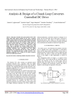
2. Evaluation of a quotation for equipment in a laboratory .......................................6
3. Standard operating procedures for equipment and instruments...........................12
4. Spectrophotometer ...............................................................................................14
5. Flame photometer ................................................................................................26
6. The microscope....................................................................................................39
7.
Manual pipettes................................................................................................51
8.
Micro pipettes ..................................................................................................54
9.
Analytical balance............................................................................................60
10.
Centrifuge ........................................................................................................65
11.
Autoclave .........................................................................................................69
12.
Refrigerator ......................................................................................................73
13.
Freezers ............................................................................................................77
14.
Hot air oven......................................................................................................78
15.
Water bath........................................................................................................79
16.
pH meter.......................................................................................................81
17
Thermometer....................................................................................................85
18
Purification of water ........................................................................................86
19.
Automation in clinical chemistry.....................................................................89
20.
Minor equipment and consumables .................................................................93
21
Condemning of unserviceable equipment........................................................94
References:...................................................................................................................95
Department of Biochemistry, Medical Research Institute, Colombo, WHO Biennium 2004-2005
ii
ACKNOWLEDGEMENTS
We would like to acknowledge the WHO representative to Sri Lanka, Dr. Kan
Tun, for identifying the need for quality assurance in local laboratories and
offering us the opportunity to publish this handbook.
We thank the Director General of Health Services, Dr. Athula Kahandaliyanage,
the Deputy Director General (Planning), Dr. T. S. B. Tennekoon and the Deputy
Director General (Education, Training and Research), Dr. Stanley De Silva,
Deputy Director General (Laboratory Services), Dr. Ajith Mendis and Director,
Laboratory Services Dr. Jayasundara Bandara, for approval and facilitation of this
project.
We are grateful to the Director of the MRI, Dr. G. S. S. K. Colombage and the
Deputy Director of MRI, Dr. Lulu Raschid for all their support and
encouragement in bringing this project to fruition.
We appreciate the assistance of administrative staff of World Health
Organisation and colleagues, resource persons, administrative staff of the Medical
Research Institute and staff of the Department of Biochemistry.
Department of Biochemistry, Medical Research Institute, Colombo, WHO Biennium 2004-2005
iii
PREFACE
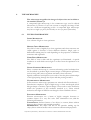
An element of good laboratory performance is the proper functioning of
laboratory equipment. The use of an instrument may be limited by inadequate
maintenance. All the major equipment in the laboratory should have a
maintenance programme. The more complex an instrument is, the more the user
will depend on the support of a supplier for its maintenance. It is therefore
pertinent to foresee the extent of costs that need to be included for the use and
maintenance of an instrument and to consider its lifespan as well as its workload.
The quality of laboratory test results depends on among other factors on the
performance of equipment. The proper functioning of equipment needs careful
operation and preventive maintenance. Early detection of malfunctions and
appropriate corrective measures will prevent unexpected costs, breakdown of
services, deterioration of quality and credibility of the laboratory. The purpose of
this manual is to address some of the fore mentioned issues and offer guidelines
for achieving greater levels of quality and functionality in selection, operation and
maintenance of laboratory equipment.
Department of Biochemistry, Medical Research Institute, Colombo, WHO Biennium 2004-2005
iv
GENERAL INTRODUCTION
The first step in optimal use of equipment is the appropriate selection of tests to
suit the needs of the population served by the clinical chemistry laboratory. To
ensure optimal use of a piece of equipment a maintenance programme should be
introduced, and aid to this programme is the preparation of the manual for
maintenance of equipment. The equipment provided must be appropriate to the
test to be performed and be in good working order. Staff, operating equipment
should be competent to do so and may be required to demonstrate this
competence. Operating manuals for equipment should be readily available and
staff handling such equipment must be able to check the critical operating
characteristics and should do so at intervals appropriate to the equipment and its
work load. Regular service checks, records of calibration, preventive care and
maintenance of each item should be kept for the life of the equipment.
In this manual the maintenance of commonly available equipment in a clinical
chemistry laboratory are included. Each equipment is described with regard to
the principle, operating procedure and maintenance. Practical and simple
calibration procedures for relevant equipment are included. However the
operating manual should be consulted for specific requirements for each
equipment.
Service manual should be available only to be used by competent biomedical
staff. The main objective of this manual is to provide guidelines to identify the
faulty performances of the equipment by the technical staff and identification of
such faults in early stages will prevent major repair costs. Rectification of the
faulty performances should be carried out by the qualified biomedical engineering
staff.
A comprehensive training should be provided to the technical staff when
purchasing expensive laboratory equipment. It is recommended that pre
marketing and post marketing evaluations be performed on each equipment at
the time of purchasing. A service agreement at least for five years should be
established at the end of the guarantee period.
The manual contains guidelines for writing up specifications for common
equipment that are used in the laboratory. The specific, critical requirements are
highlighted for each equipment. The procedure for assessment of quotations
supplied by the local agents is included in this manual to guide the laboratory
staff to obtain the cost effective, best equipment. A format of a maintenance log
book for critical equipment is also introduced.
Department of Biochemistry, Medical Research Institute, Colombo, WHO Biennium 2004-2005
1
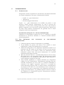
1.
GUIDELINES FOR SELECTION OF LABORATORY EQUIPMENT
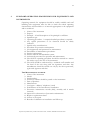
1. Consider the requirement of the equipment
TO UPGRADE AN EXISTING LABORATORY
Introduce a new test
Replace non functioning or inadequate equipment
Improve performance of an existing test
TO ESTABLISH A NEW LABORATORY
To determine the type of tests required, consult the clinical staff and
other laboratory users. The tests should be relevant, cost effective and
reliable. Consult the health authorities regarding the local requirement,
funding and other factors (personnel, equipment, reagents, consumables,
and training of staff) which contribute to an uninterrupted service.
2. Analyse in detail the conditions and resources:
FUNDS:
Government funds through the ministry of health
Donor agency (donor requirements should be compatible with the
policies of the government
INFRASTRUCTURE FACILITIES:
Buildings and space
Power supply/generator facility
Water supply
Drainage and disposal of waste
RESOURCES / ENVIRONMENTAL CONDITIONS
Availability of reagents, consumables and stationary
Conditions of the existing equipment:
Comparability
Reliability
Function
Requirements of the new equipment with regard to maintenance,
availability of spare parts and back up system
Availability of personnel and technical training
Supervision of the performance of the equipment and service
Type of sample and mode of transport to the laboratory
Department of Biochemistry, Medical Research Institute, Colombo, WHO Biennium 2004-2005
2
3. A systematic, comprehensive cost analysis is recommended on yearly basis
for a given test over a given instrument considering the following factors.
Workload
Acquisition costs (capital investment: purchase, lease or rental)
Man power needs and costs
Preventive maintenance costs
Reagents and disposable items costs
Service contract costs
Cost adjustments: effect of inflation on reagent and disposable item costs
4. Organize meetings with health authorities, clinicians and laboratory staff
regarding the relevant factors for each category
5. A comprehensive technical analysis of the instrument should be carried out
with the assistance of relevant technical experts.
DURABILITY IN LOCAL CONDITIONS
The instrument should withstand the local environmental conditions such
as humidity, dust, drought, low or high temperatures. The electronics of
the instrument should be protected against humidity during the
manufacturing process.
ENVIRONMENTAL CONDITIONS
Some instruments need special environmental conditions such as an air
conditioned area.
LOCATION OF THE EQUIPMENT
Availability of the building/floor/ bench area with regards to the
suitability and safety should be considered.
Any other physical requirement recommended by the manufacturer.
SAFETY OF THE INSTRUMENT
Consider the risks and dangers associated with the operation of the
equipment to the technical staff and local community.
Consider the safety requirements which are mandatory during operation
of the equipment
The manufacturer should be able to install and provide advice on
maintenance to ensure safe performance.
Department of Biochemistry, Medical Research Institute, Colombo, WHO Biennium 2004-2005
3
POWER, GAS AND WATER SUPPLY
POWER SUPPLY: Availability of constant and reliable power supply
should be considered.
The power requirements of the equipment in relation to the availability of
electricity to the laboratory
A voltage stabilizer/uninterrupted power supply should be purchased
with the equipment.
If the equipment is battery powered, the type of battery, rechargeable/
non- rechargeable and replacement should be considered.
GAS SUPPLY: Type of gas: pipe borne or cylinders (capacity of cylinders):
hazardous nature of the gas: flammable gas should be stored out side the
building:
WATER SUPPLY: Type of water available (hard/soft): Special
requirements of water for the instrument (Type 1, 2 reagent grade water):
The additional equipment required to produce the specified type of water
should be considered. e.g. deionizer and spare parts, consumables
SUSTAINABILITY
The instrument, replacement spare parts, consumables, supplies and
reagents should be in the manufacturing line for at least for another 10
years.
The cost of repairs, replacements and consumables should be considered.
During the guarantee period an agreement should be made in writing that
the instrument be replaced due to faults in the manufacturing process.
A service agreement should be available for the next five years.
REAGENTS, CONSUMABLES AND DISPOSABLE ITEMS
The instrument may be an open/closed system with regards to reagents.
A comprehensive study should be carried out regarding the availability of
reagents, costs, and requirements for storage (refrigeration, cold rooms)
stability and the mechanism for continuous supply.
ACCESSORIES
The additional requirements for the functioning of the equipment should
be considered. (Computer and printer)
TRAINING REQUIREMENT
Consider the adequacy of the level of training and expertise of the
laboratory staff and decide on any additional training requirements to
operate and maintain the equipment. The installation, operation and
service manuals should be provided with the equipment.
Department of Biochemistry, Medical Research Institute, Colombo, WHO Biennium 2004-2005
4
SPARE PARTS
The manufacturer should provide a list of essential spare parts and a
guide to the life expectancy of the spare parts. The local agent should
demonstrate the capacity to service and maintain the equipment.
The number of spare parts that should be ordered depends on the life
expectancy of the part, the cost, the ability to fit the part by the local staff
or agent and the reliability of storage of the spare part.
The spare parts are expensive and needs to be imported from the
manufacturer. There fore maximum relevant information should be given
such as manufacturer’s name, country of origin, model or type, serial
number, a description of the part and the voltage, wattage of electrical
parts.
MAINTENANCE
Make a request from the manufacturer/local agent to provide staff
training in preventive maintenance and handling of trouble shooting. The
local agent should provide immediate remedy to overcome a sudden
breakdown of equipment.
Study the manufacturer’s guarantee with regards to the period, spare
parts, repair and replacement. Any equipment faults due to
manufacturing process should be replaced during the warranty period.
Study the hidden terms and conditions laid down by the local agent
regarding maintenance.
A service agreement should be established at the end of the warranty
period. The local agent should specify the services in detail that will be
offered during the service contract.
TECHNICAL REQUIREMENTS OF THE INSTRUMENT
The proper selection of the equipment depends on the specifications of
the critical elements of the proposed instrument. (e.g. band width of a
spectrophotometer is one of the critical elements in deciding on the type
of spectrophotometer to be purchased)
All the critical factors should be written when submitting the
specifications for an instrument.
A detailed study/survey should be carried out on the instruments
available in the market. The local agents should be contacted to obtain
the brochures to note the technical details of the equipment. The
manufacturers are likely to comment only on the favourable features not
the limitations of the instrument. Therefore manufacturer’s specifications
should not be taken as a guide to define your requirements. Request a list
of customers who have purchased similar equipment. You may visit these
laboratories to observe the operation, calibration, quality control
practices, maintenance and views on after sales service. It is
recommended to request a demonstration of the functioning of the
equipment in your own setting where possible. (E.g. pipettes, pH meter,
balance, spectrophotometer etc) Equipment data specification sheets
should be prepared by the laboratory and submitted at the requisitioning
Department of Biochemistry, Medical Research Institute, Colombo, WHO Biennium 2004-2005
5
to ensure that the purchasing officer can justify the expenditure and has
sufficient information to buy the items correctly.
IN GENERAL A SPECIFICATION SHEET INCLUDES THE FOLLOWING:
Name of the Institution
Description of the service
Name of the equipment
Model (if applicable only)
Value of equipment
Intended use
Technical specifications
Requirements for preventive maintenance
Reagents, consumables, disposable items
Guarantee period
Availability of spare parts
Service contract
Power/gas/water requirement
Voltage stabilizer/UPS
Training requirement
The unit price/total price with and without taxes should be requested
from the local agents
Include the phrase “complete functioning unit of ……….” in the
specifications so that the local agent is required to mention any other
requirements and costs for such facilities.
Department of Biochemistry, Medical Research Institute, Colombo, WHO Biennium 2004-2005
6
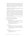
2.
EVALUATION OF A QUOTATION FOR EQUIPMENT IN A
LABORATORY
A request should be made to the local supplier/manufacturer to submit a
quotation for the goods or services. At least three such requests should
be made, in order to obtain the best equipment for the best price. A
comprehensive data specification sheet should accompany such a request.
The supplier will prepare the document providing the details of
equipment and the prices. The end users will evaluate the quotations. The
evaluation procedures may differ depending on your local requirements.
The following procedure is recommended.
Appoint a team for the evaluation. The team should consist of
members of staff who are competent in technical procedures. The
person who intends to operate the equipment should be included in
the team. The chairperson should ensure that the confidentiality of
the process is maintained by all the members.
Each member of the team is responsible for the final decision.
Preferably each member should be given copies of the documents to
evaluate individually. This will provide the opportunity to study the
quotations thoroughly to make the correct selection. Then the team
should meet with the chairperson and a final selection should be
made on credible scientific basis.(All the copies of the documents
should be returned to the head of the institution along with the
evaluation report)
Write down each feature of the specifications of the instrument and
match with the features given in the quotations. Include the prices
clearly. Make the best selections with regards to suitability, reliability
timely delivery and cost. Once the technical validation is fulfilled
consider the cost of the equipment and other services.
It is important to consider the availability and reliability of the after
sales service.
You should justify your acceptance and rejection. You may be
required to give your valid reasons to reject the low cost equipment
and accept the one with a higher price.
At this point one cannot alter/add/delete the specifications and
requirements.
If none is satisfied you may be able to request fresh quotations from
different suppliers.
The evaluation report should be submitted by placing the date and
signatures of the evaluation team.
Department of Biochemistry, Medical Research Institute, Colombo, WHO Biennium 2004-2005
7
A copy should be retained in the laboratory for future references and
to ensure the delivery of the selected equipment and services. The
head of the unit or the chairperson should ensure the confidentiality
of the retained copy.
A tender is also a request for costs. Generally a tender is for a large
order, over a certain value. Therefore strict procedures are adhered in
evaluating the tenders.
Both processes will be subjected to annual audit by the government
and all records should be available for inspection.
Therefore you are required to have a sound knowledge of the local
procedures (country, province, institution,) pertaining to evaluation
of equipment.
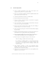
An example of data evaluation sheet for a quotation is given below
Department of Biochemistry, Medical Research Institute, Colombo, WHO Biennium 2004-2005
8
DATA EVALUATION SHEET FOR A QUOTATION
Quotation reference number
Name of the unit/hospital
(Dept. of Biochemistry,M.R.I)
Evaluation of quotations submitted for (name of the equipment)
Date of receipt of quotations
Date of submission of the evaluation report
Members of the evaluation team
Signature
1.
2.
3.
Quotation 1
Quotation 2
Quotation 3
Name of the item
Purpose
Model
Manufacturer
Country of origin
Assembled
Manufacturer/local
Local agent
Critical technical
feature 1
2
3
General
1
2
requirement
3
Accessories
Spare parts
Warranty
Service contract
Availability of manuals
Training
Maintenance
Department of Biochemistry, Medical Research Institute, Colombo, WHO Biennium 2004-2005
9
Quotation 1
Unit price
Total price
Unit price with taxes
Total price with taxes
Costs in the ascending
2
order
higher price
Technical requirements
Satisfactory/
unsatisfactory
General requirements
Satisfactory/unsatisfactory
Accepted/rejected
Reasons
Quotation 2
Quotation 3
1
lowest price
3
highest price
Comments:
Department of Biochemistry, Medical Research Institute, Colombo, WHO Biennium 2004-2005
10
GUIDELINES TO BE FOLLOWED ON RECEIPT OF NEW
EQUPIMENT IN THE LABORATORY
The supplier should inform the laboratory the expected date and time
of the delivery of goods. The delivery should preferably be done on a
working day of the week, few hours before the closure of the
laboratory.
Follow the institutional rules/regulations regarding the receipt of
laboratory equipment. Documentation at the stores/office should be
made before the item is delivered to the laboratory.
Inspect the packing for any damages in the presence of the
representative of the local agent. If any damages are suspected, notify
the local agent and relevant authorities.
If the packing is intact and no damage to the equipment is
anticipated, unpack the equipment carefully. Retain all the packaging,
labels, supports and booklets.
Check the instrument for damages. If it appears damaged inform the
supplier in writing through the head of the unit and institution.
Request the technical staff of the local agent to assemble and to
perform a ‘’test run’’ using the installation and operation manuals.
Check whether the delivered instrument meets the specifications of
the quotation. Any discrepancies should be notified to the supplier
through the head of the unit and institution. All the operational
procedures should be stopped until the acquisition of the correct
instrument.
If the correct instrument is delivered read and follow the installation,
operational and service manuals.
The technical representative of the local agent should be able to
demonstrate a satisfactory test run.
The training of the technical staff of the laboratory should be carried
out under the supervision of the technical staff of the company.
Follow the relevant procedure for equipment evaluation.(e.g. a
spectrophotometer should be calibrated and test run of quality
control material for each test should be performed: A balance should
be calibrated for weighing)
Check whether the other requirements are fulfilled according to the
quotation.(supply of accessories, spare parts, consumables, reagents )
Read the conditions of the warranty.
Department of Biochemistry, Medical Research Institute, Colombo, WHO Biennium 2004-2005
11
Once the user is satisfied with the performance of the equipment and
other relevant conditions, approval for payments should be given to
the head of the institution through the head of the unit.
The inventory holder of the laboratory should make the
documentation in the inventory and the inventory number should be
clearly written and pasted on to the instrument.
Maintain the log book with regards to the conditions at installation
and preventive maintenance. ( e.g.; records of calibration) Any repairs
and replacements should be entered in the book.
A separate record should be maintained to include the entries of the
users. (Name of the user, date, time and trouble shooting and
corrective measures should be recorded.)
A standard operating procedure for the equipment should be
prepared and be readily available for reference by the users.
The operational procedure in brief should be available at the
bench/site of the instrument.
Only the authorised trained personnel should use the instrument. Any
other persons should obtain permission from the inventory holder
and should operate the instrument under the supervision of trained
personnel.
Department of Biochemistry, Medical Research Institute, Colombo, WHO Biennium 2004-2005
12
3.
STANDARD OPERATING PROCEDURES FOR EQUIPMENT AND
INSTRUMENTS
Operating manuals for equipment should be readily available and staff
handling such equipment must be able to check the critical operating
characteristics and should do so at intervals appropriate to the equipment
and its workload.
1.
2.
3.
4.
5.
6.
7.
8.
9.
10.
11.
12.
13.
14.
15.
Name of the instrument
Purpose
Principle - A brief description of the principle is sufficient.
Specimen type
Operating procedure - A stepwise detailed procedure is required.
Any special precautions to be observed should be clearly
indicated
Special safety considerations
Procedure for preventive maintenance
Job assignments and personnel for maintenance.
Surveillance of maintenance procedures.
Service requirements
Service intervals and remainder system.
Authorized personnel for operation and maintenance.
The SOP for operating procedure should be retained in a master
file with a copy at the site of the instrument.
The SOP should be authorized by a technical staff member and
the head of the unit along with the signatures and date. Any
amendments should be carried out only by the above personnel,
again with signature and date.
THE MAINTENANCE LOG BOOK
1. Name of the instrument
2. Model
3. Serial number
4. Inventory number should be pasted on the instrument.
5. Date of purchase
6. Manufacturer
7. local agent – address/ telephone /email
8. Performance of the instrument at installation
9. Preventive maintenance records (daily, monthly and 6 month
intervals)
10. Supervisor’s observation of preventive maintenance
11. Repair or replacement dates
12. Nature of the repair
13. Records of calibration at installation and follow up
Department of Biochemistry, Medical Research Institute, Colombo, WHO Biennium 2004-2005
13
DATASHEET TO BE USED BY THE SUPERVISOR
Name of the Institution
Description
Type of Instrument
Name of the equipment
Model
Value of equipment
Country of manufacture
Date of manufacture
Name of manufacturer
Agent / Local Agent
Contact Number
Date of receipt
Date of installation
Original condition
Current condition
No. of repairs
Last date of repair
Nature of repair / cost
Availability of manual
Tests performed by the
equipment
Evaluation of performance
Infrastructure required
Maintained by:
Department of Biochemistry, Medical Research Institute, Colombo, WHO Biennium 2004-2005
14
4.
SPECTROPHOTOMETER
The clinical chemistry determinations are based on measurements of light
absorption. The photometer and spectrophotometer are optical instruments for
the measurement of light absorption.
BEER – LAMBERT’S LAW
The Beer-Lambert’s law states that when a monochromatic light traverses
a solution, the concentration of the dissolved substance is directly
proportional to the amount of radiant energy absorbed or inversely
proportional to the logarithm of the transmitted radiant energy. If the
concentration of a solution is constant and the path length through the
solution that the light must traverse is doubled, the effect on the
absorbance is the same as doubling the concentration, since twice as
many absorbing molecules are now present in the radiant energy path.
Thus the absorbance is also directly proportional to the path length of the
radiant energy through the cell (cuvette).
The mathematical relationship that connects absorbance of radiant energy,
concentration of a solution and path length is shown by Beer – Lambert law
A = abc
A is absorbance; a, absorptivity; b, light path of the solution in centimetres and c,
concentration of the substance of interest.
The equation forms the basis of quantitative analysis by absorption photometry.
Absorbance values have no units. The absorptivity is proportionality constant
related to the chemical nature of a solute and has units that are reciprocal of
those for b and c.
When c is expressed in moles per litre and b is expressed in centimetres, the
symbol є called the molar absorptivity, is used in place of a and is a constant for a
given compound at a given wavelength under specified conditions of solvent,
pH, temperature and so on. It has units of L/mole.cm. The higher the molar
absorptivity, the higher is the absorbance for the same mass concentration of two
compounds. Therefore in selecting a chromogen for spectrophotometric
methods, one should use the chromogen with a higher molar absorptivity, which
will impart a greater sensitivity to the measurement.
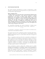
Once a chromogen is proved to follow Beer –Lambert’s law at a specific
wavelength, that is a linear plot of absorbance versus concentration, with a zero
intercept, the concentration of an unknown solution can be determined by
measurement of its absorbance and interpolation of its concentration from the
graph of the standards. In contrast, when % of transmittance is plotted versus
concentration [on liner graph paper], a curvilinear relationship is obtained.
Because of the liner relationship between absorbance and concentration it is
Department of Biochemistry, Medical Research Institute, Colombo, WHO Biennium 2004-2005
15
possible to relate unknown concentrations to a single standard by a simple
proportional equation. Therefore
Absorbance of the standard = Concentration of the standard
Absorbance of the unknown
Concentration of the unknown solution
solution
Concentration of the
unknown solution
Absorbance of the
Concentration of the
= unknown solution x Standard
Absorbance of the standard
The above equation is valid only if the chromogen obeys the Beer’s law and both
standard and unknown are measured in the same cell. The concentration range
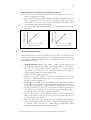
over which a chromogen obeys Beer –Lambert’s law must be determined for
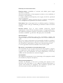
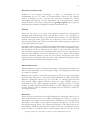
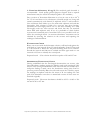
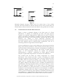
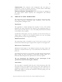
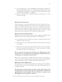
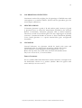
each set of analytical conditions. A calibration graph is drawn with the
absorbance versus concentration.
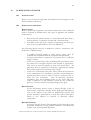
Absorbance
Concentration
Relationship of absorbance to concentration
Beer-Lambert’s law is an ideal mathematical relationship that contains several
limitations. Deviations from Beer’s law that is variations from the linearity of the
absorbance versus concentration curve occur when
1. Highly elevated concentrations are measured.
2. Incident radiant energy is not monochromatic
3. The solvent absorption is significant compared with the solute absorbance
4. Radiant energy is transmitted by other mechanisms [stray light].
5. The sides of the cell are not parallel.
If two or more chemical species are absorbing the wavelength of incident radiant
energy, each with a different absorptivity or if the absorbance of a fluorescent
solution is being measured Beer- Lambert’s law will not be followed.
Department of Biochemistry, Medical Research Institute, Colombo, WHO Biennium 2004-2005
16
4.1
INSTRUMENTATION
PHOTOMETER AND SPECTROPHOTOMETER
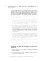
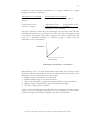
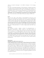
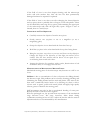
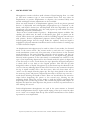
The major components of a spectrophotometer are shown in the diagram below.
The apparatus can be divided into seven basic components;[1] a stable source of
radiant energy, [2] an entrance slit to focus the light ,[3]a wavelength selector[4]an
exit slit to focus the light [5] a device to hold the transparent container[ cuvette] ,
which contains the solution to be measured ,[6]a radiant energy detector. [7] A
device to read the electrical signal generated by the detector.
If a filter is used as the wavelength selector, monochromatic light at only discrete
wavelength is available, and the instrument is called a photometer. If a
monochromator is used (a prism or grating) as the wavelength selector, the
instrument can provide monochromatic light over a continuous range of
wavelengths and is called a spectrometer or spectrophotometer.
Spectrophotometers can be single beam instruments with a single cuvette
holder or double –beam instruments with two cuvette holders, one for the
sample and the other for the blank; or reference sample .Advantages of the
double –beam instrument include the capability of making simultaneous
corrections for changes in light intensity, grating efficiency, slit width variation
and it is particularly useful for obtaining spectral curves.
SOURCES OF RADIANT ENERGY
Tungsten – filament lamp is used as the source of a continuous spectrum of
radiant energy from 360 to 950 nm, Tungsten iodide lamps are often used as
sources of visible and near ultraviolet radiant energy. The tungsten halide
filaments are longer lasting, produce more light at shorter wavelengths and emit a
higher intensity radiant energy than tungsten filaments do. Hydrogen and
deuterium discharge lamps emit a continuous spectrum and are used for the
ultraviolet region of the spectrum [220 to 360 nm.] The deuterium lamp has more
intensity than the hydrogen lamp does. The amount of light emitted from a light
source is not constant over a continuous range of wave lengths. A typical lamp
has a complex transmittance spectrum with maxima and minima. One must take
care in choosing a lamp for a particular analysis, since the amount of light emitted
at the desired wavelength may be too little or too much.
Department of Biochemistry, Medical Research Institute, Colombo, WHO Biennium 2004-2005
17
WAVELENGTH SELECTORS
Isolation of the required wavelength or range of wavelengths can be
accomplished by use of a filter or monochromator .Filters are the simplest
devices, consisting of only a material that selectively transmits the desired
wavelengths and absorbs all other wavelengths .In a monochromator radiant
energy from the source lamp is dispersed by a grating or prism into a spectrum
from which the desired wavelength is isolated by mechanical slits.
FILTERS
There are two types of [1] those with selective transmission characteristics
including glass and Wratten filters and [2] those based on the principle of
interference [interference filters] The Wratten filter consists of coloured gelatin
between clear glass plates; glass filters are composed of one or more layers of
coloured glass; Both types of filters transmit more radiant energy in some parts
of the spectrum than in others.
Interference filters work on a different principle. When radiant energy strikes the
thin film, some is reflected from the front surface, but some of the radiant energy
that penetrates the film is reflected by the surface on the other side. The latter
rays of radiant energy have now travelled farther than the first by a distance two
times the film thickness. If the two reflected rays are in phase, their resultant
intensity is doubled, whereas, if they are out of phase, they destroy each other.
Therefore when white light strikes the film, some reflected wavelengths will be
augmented and some destroyed resulting in colours.
MONOCHROMATORS
Monochromators can give a much narrower range of wavelength than filters can
and are easily adjustable over a wide spectral range .The dispersing element may
be a prism or a grating.
Dispersion by a prism is non linear, becoming less linear at longer wavelengths
[over 550 nm]. Therefore to certify wavelength calibration ,one must check three
different wavelengths .Prisms give only one order of emerging spectrum and
thus provide higher optical efficiency, since the entire incident energy is
distributed over the single emerging spectrum. A grating consists of a large
number of parallel equally spaced lines ruled on a surface .Dispersion by a grating
is linear, therefore only two different wavelengths must be checked to certify the
wavelength accuracy.
BAND PASS
Except for laser optical devices, the light obtained by a wavelength selector is not
truly monochromatic [that is of a single wavelength] but consist of a range of
wavelengths. The degree of monochromicity is defined by the following terms.
Band pass is that range of wavelengths that passes through the exit slit of the
wavelength-selecting device. The nominal wavelength of this light beam is the
wavelength at which the peak intensity of light occurs. For a wavelength selector
such as a filter or a monochromator whose entrance and exit slits are of equal
Department of Biochemistry, Medical Research Institute, Colombo, WHO Biennium 2004-2005
18
width, the nominal wavelength is the middle wavelength of the emerging
spectrum.
The range of wavelengths obtained by a filter producing a symmetrical spectrum
is usually noted by its half-band width [or half- band pass]. This describes the
wavelengths obtained between the two sides of the transmittance spectrum at a
transmittance equal to one half the peak transmittance. For monochromators the
degree of monochromicity is described by the nominal band width, which
corresponds to those wavelengths that are cantered about the peak wavelengths
and transmit 75% of the total radiant energy present in the emerging beam of
light. For monochromators with variable exit slits, the band pass will also vary.
SLITS
There are two types of slits present in monochromators. The first, at the
entrance, focuses the light on the grating or prism where it can be dispersed with
a minimum of stray light .The second slit at the exit, determines the band width
of light that will be selected from the dispersed spectrum. By increasing the width
of the exit slit, the band width of the emerging light is broadened with a resultant
increase in energy intensity but a decrease in spectral purity. In diffraction-grating
monochromators the exit slit may be of fixed width, resulting a constant band
pass .In contrast prism monochromators have variable exit slits. The purpose of
both slits in filter photometers is to make the light parallel and reduce stray
radiation.
CUVETTES
The receptacle in which a sample is placed for spectrophotometric or
photometric measurement is called a cuvette or cell. Glass cuvettes are
satisfactory for use in the range of 320 to 950 nm For measurements below 320
nm it is necessary to use quartz[silica]cells .Such cells can be used at higher
wavelengths also. Cuvettes with a square cross section and with a circular cross
section [that is test tubes]are available, Greater accuracy is achieved by square
cuvettes with parallel sides made of optical glass. Although cuvettes usually have
internal dimensions[that is path lengths] of 1 cm, cuvettes with other dimensions
are available. Macro cuvettes (with 1 cm path length and 2 ml volume), micro
cuvettes (with 1 cm path length and 1 ml volume) are used in clinical chemistry
determinations.
DETECTORS
BARRIER LAYER [PHOTOVOLTAIC] CELLS.
Barrier layer cells are detectors consisting of a plate of copper or iron on which is
a semi conducting layer of cuprous oxide or selenium is placed. This layer is
covered by a light transmitting layer of metal that serves as a collector electrode.
As illumination passes through the transparent electrode to the semi conducting
layer an electron flow is induced in the semi conducting layer and this flow can
be sensed by an ammeter, These detectors are rugged relatively inexpensive and
sensitive from the ultraviolet region up to about 1000 nm No external power is
required and the photocurrent produced is essentially directly proportional to the
radiant energy intensity. Barrier layer cells exhibit the fatigue effect which means
that on illumination, the current rises above the apparent equilibrium value and
then gradually decreases.
Department of Biochemistry, Medical Research Institute, Colombo, WHO Biennium 2004-2005
19
PHOTOMULTIPLIER TUBES
A photomultiplier tube is an electron tube that is capable of significantly
amplifying a current. The cathode is made of a light-sensitive metal that can
absorb radiant energy and emit electrons in proportion to the radiant energy that
strikes the surface of the light sensitive metal. These surfaces vary in their
response to light of different energies [wavelengths] and so also in the sensitivity
of the photomultiplier tube. The electrons produced by the first stage go to a
secondary surface, where each electron produces between four and six additional
electrons .Each of the electrons from the second stage goes on to another stage,
again producing four to six electrons. As many as 15 stages [or dynodes] are
present in today’s photomultiplier tubes. Photomultiplier tubes have rapid
response times. Do not show as much fatigue as other detection and are very
sensitive.
PHOTODIODE
Photodiodes are semiconductors that change their charged voltage [usually 5 V]
upon being struck by light. The voltage change is converted to current and is
measured A photodiode array is a two dimensional matrix composed of hundreds
of thin semiconductors spaced very closely together. Light from the instrument is
dispersed by either a grating or prism onto the photodiode array. Each position
or diode on the array is calibrated to correspond to a specific wavelength. Each
diode is scanned and the resultant electronic change is calculated to be
proportional to absorption. The entire spectrum is essentially recorded within
milliseconds.
Department of Biochemistry, Medical Research Institute, Colombo, WHO Biennium 2004-2005
20
4.2
PERFORMANCE OF THE INSTRUMENT
The sensitivity of response of a spectrophotometer is a combination of lamp
output, efficiency of the filter or monochromator in the transmission of light, and
response of the photomultiplier. As these factors are all functions of wavelength
it is clear that the instrument must be reset when one changes wavelengths. This
resetting most often takes the form of adjustment of the blank solution to read
zero absorbance by changing the photomultiplier gain.
SELECTION OF OPTIMUM CONDITIONS AND LIMITATIONS
When one is establishing a new spectrophotometric procedure it is important to
record the absorption spectrum of the material in relation to either water or a
reagent blank, depending on the actual method of analysis. The optimum
wavelength for a specific analysis will depend on several factors, including the
absorption maxima of the chromogen, the slope of the absorption peak and the
absorption spectra of possible interfering chromogens. As a general rule for
wavelength selections are based on three criteria. (1) Choose an absorption peak
with the greatest possible molar absorptivity (2) Choose a relatively broad peak
(3) Choose a peak that is as far as possible from the absorption peaks of
commonly interfering chromogens.
4.3
CALIBRATION OF SPECTROPHOTOMETER
(A practical and simple method)
4.3.1
CALIBRATION OF SPECTROPHOTOMETER – UV RANGE
Wavelength and Photometric Checks Using Liquid Solutions of
Substances with known Absorption Characteristics
Acid
Potassium Dichromate
REAGENTS
1. Sulphuric acid 5 mmol/L
Calculation of volume of concentrated sulphuric acid to be added.
(Molecular weight = 98.08 g, Specific Gravity =1.84)
1 M solution
= 98.08 g/L
1mmol
= 0.09808 g/L
5mmol
= 0.4904 g/L
Weight of 1 ml
= 1.84 g
Required volume (ml)
of conc. sulphuric acid
= 0.4904 =
1.84
0.2665
= 0.27 ml
Add about 800 ml of distilled water in to a 1 litre beaker Keep the beaker
in a basin of water. Carefully add 0.27 ml of conc. sulphuric acid into the
beaker. Allow it to cool Mix and transfer in to a 1 litre volumetric flask
Mix well. Adjust the final volume to 1 litre. Mix well. Transfer into a
brown bottle. (Observe the precautions in handling corrosive acids)
Department of Biochemistry, Medical Research Institute, Colombo, WHO Biennium 2004-2005
21
2. Potassium dichromate, 50 mg/L (The analytical grade chemical is
recommended. Good quality general purpose reagents from a reputed
manufacturer may be used if the analytical grade is not available. ).
Dry a portion of Potassium dichromate in a hot air oven at 80 to 90 0C
for 3 to 4 h and then cool in a desiccator. Carefully weigh out 50 mg and
transfer quantitatively with 5mmol/L sulphuric acid to a well washed 1
Litre volumetric flask. Make up to the mark with sulphuric acid and mix
thoroughly. This solution is stable for a year but may show layering.
Therefore mix thoroughly before use if it has been standing for a time
Thoroughly wash two silica cuvettes and check that they are matched
when filled with sulphuric acid. If not it is preferable to check further
cuvettes until a matched pair is found but if this is not possible it will not
affect the wavelength check. An accurate absorbance assessment can be
obtained by reversing the solutions in the cuvettes and repeating the
readings as indicated below
WAVELENGTH CHECK
Rinse one cuvette with the dichromate solution, refill and read against the
acid blank at 5 nm intervals from 370 nm downwards. From 355 nm read
at 1 nm intervals to define the flat peak stretching from 352 to 348 nm.
Extend the interval until 260 nm is reached and then again read at 1 nm
intervals to 255 nm to identify the second peak.
Expected result : The solution should show peaks at 350 and 257 nm
ABSORBANCE (EXTINCTION) CHECK
Having established that the wavelength characteristics are correct, take
three absorbance readings against the blank at each peak wavelength (350
and 257 nm) zeroing the instrument each time with the acid solution (If a
null-point reading is made, move the absorbance setting away from its
previous position initially) Rinse the cells and reverse the solutions, repeat
the readings in triplicate and take the mean of all six readings for each
peak. This eliminates errors due to unmatched cuvettes if these were not
matched originally.
Expected result: The mean absorbance should be 0.535 ± 0.005 at 350
nm and 0.720 at 257 nm.
Department of Biochemistry, Medical Research Institute, Colombo, WHO Biennium 2004-2005
22
LINEARITY CHECK
Potassium Dichromate solution 200mg/L
Carefully weight out 200 mg of dried potassium dichromate [as given
above] and transfer quantitatively with sulphuric acid in to a well-washed
1 litre volumetric flask Make up to the mark with sulphuric acid and mix
thoroughly.
Sulphuric acid 5 mmol/L
Dilute 200 mg/L potassium dichromate solution with sulphuric
acid 5 mmol/l according to the table given below:
200 mg/L Potassium 5 mmol/L Sulphuric Concentration
Dichromate
Acid
1.0ml
9.0ml
20 mg/L
3.0ml
7.0ml
60 mg/L
5.0ml
5.0ml
100 mg/L
7.0ml
3.0ml
140 mg/L
9.0ml
1.0ml
180 mg/L
Take the spectrophotometer readings at 350 nm against the acid blank.
Plot the absorbance readings against the concentrations on a graph paper
and check the linearity.
STRAY LIGHT
Stray light can cause significant departures from Beer’s law, with resultant
loss of photometric accuracy particularly with higher absorbance values in
the UV region. It is defined as unwanted radiation energy sensed at the
detector.
MEASUREMENT OF STRAY LIGHT:
Set the wavelength of the spectrophotometer to 340 nm and set the
reference or blank [100% transmission)] with distilled water in the sample
compartment. Place the cuvette containing Sodium nitrite 5 g /100ml in
the cuvette compartment. Sodium nitrite acts as a blocking filter,
absorbing all incident radiation at the wavelength selected but
transmitting virtually all of the radiation at longer wavelengths. Therefore
any transmission recorded at 340 nm will be a direct measurement of the
stray light of the instrument.
Expected result: stray light should be < 0. 1%
An instrument malfunction is indicated whenever the amount of stray
radiation exceeds 1%
Department of Biochemistry, Medical Research Institute, Colombo, WHO Biennium 2004-2005
23
4.3.2 CALIBRATION OF SPECTROPHOTOMETER – VISIBLE
RANGE
(A simplified procedure is described, extracted from W.HO /LAB/89.2)
PHOTOMETRIC LINEARITY
EQUIPMENT AND MATERIALS
Spectrophotometer
Matched cuvettes
Centrifuge
HiCN stock solution
Potassium ferricyanide
Potassium cyanide
Potassium dihydrogen Phosphate (KH2PO4) anhydrous
Carbon tetrachloride
FERRICYANIDE/CYANIDE REAGENT
Weigh and dissolve in 800 ml of distilled or deionised water in a 1 litre
volumetric flask: 200 mg of potassium ferricyanide, 50 mg of potassium
cyanide (Note: Highly poisonous by ingestion or inhalation; Handle with
extreme care), and 140 mg of potassium monobasic phosphate
(anhydrous). Add 1 ml of Tween 20. Dilute with deionised or distilled
water to 1000 ml. The pH of the reagent should be between 7.0 and 7.4;
this should be checked with a pH meter, if possible. The absorbance at
540 nm read against distilled water blank should not exceed 0.002 A; the
colour is pale yellow. If the reagent is stored between 4 and 250 C in
stoppered borosilicate bottles, in the dark, it will keep for at least two
months. It should not be frozen.
PREPARATION OF STOCK HICN
A 0.5 ml aliquot of whole blood with a Hb concentration between 135
and 145 g/l is added to about 20 ml of ferricyanide/cyandide reagent and
about 0.5 ml of carbon tetrachloride. Mix well. Stand the solution for an
hour with occasional mixing. Divide the solution evenly into two 15 ml
centrifuge tubes and centrifuge at 2500 g for 10 minutes. The clear
solution is decanted from any solid residue and from CCl4 into a 100 ml
volumetric flask and diluted to the mark with ferricyanide/cyanide
reagent. The absorbance measured at 540 nm should lie between 0.450
and 0.500 A; if necessary, the entire solution may be diluted with reagent.
Department of Biochemistry, Medical Research Institute, Colombo, WHO Biennium 2004-2005
24
PREPARATION OF HICN DILUTIONS.
Using 5ml and 10 ml class A, TD (“to deliver”) pipettes (15 and 20 ml
pipettes may also be used ) and ferricyanide reagent as a diluent, prepare
dilutions of the above stock HiCN by pipetting the volumes below into
separate containers:
Abs of
Abs of
Solutions Stock
Ferricyanide Hb%
HiCN/ml Reagent/ml Calibrated Calibrated Candidate
Spectro:
Spectro:
Spectro:
1
25
2
20
5
3
15
10
4
10
15
5
5
20
PROCEDURE
Zero the instrument with the reagent blank(Ferricyanide reagent)
Measure the Hb concentration and corresponding absorbances of
all five solutions from a calibrated spectrophotometer
Measure the absorbance of each solution from the candidate
spectrophotometer
Plot a graph using the Hb concentration/absorbances obtained
from the calibrated spectrophotometer Vs absorbances of the
candidate spectrophotometer
A linear response through the origin is expected.
PHOTOMETRIC PRECISION
A complex procedure available for the determination of imprecision in
W.H.O LAB 89.2 (The details of an example available at the Department
of Biochemistry.)
SELECTION OF THE WAVELENGTH/FILTER
Analyse one mid-range standard (e.g. 2.5mmol/l standard for
calcium) solution and the reagent blank by the given method.
Measure the absorbances of these solutions against a distilled
water blank, using each wavelength/filter in turn. Note the
readings.
Select the wavelength/filter which gives the largest difference
between the standard and reagent blank readings. Establish a
linear calibration graph and determine the upper limit of the
linearity.
Department of Biochemistry, Medical Research Institute, Colombo, WHO Biennium 2004-2005
25
CARE AND MAINTENANCE OF SPECTROPHOTOMETERS
Set the instrument up on a level bench where it will be free from
vibrations and not in direct sunlight
Instrument should be protected from dust with a cover.
Manufacturer’s instructions should be adhered during installation,
operation and maintenance.
Standard operating procedures should be prepared including the use
cuvettes, operation of the instrument and waste disposal. Records of
maintenance and absorbance readings of blank and standard for each
analyte should be documented. A decrease in absorbance readings is one
of the early signs of deterioration of lamp energy.
Calibrations are recommended at installation, 6 month intervals and
following a repair or replacement (e.g. replacement of a lamp). Any
deviations in calibration should be rectified by competent biomedical
technical staff.
THE
FACTS TO
SPECIFICATIONS.
BE
CONSIDERED
FOR
DOCUMENTATION
OF
Type of instrument (colorimeter/ spectrophotometer) depends on the
range of tests done at the laboratory.
Type of spectrophotometer (visible only, uv- visible, with or without
recording facility, with or with out temperature control) depends on the
type of tests (absorbance, kinetic or scanning measurements)
Band width is an important determinant of the nature of the
monochromatic light obtained for measurements.
Accessories (cuvettes, stabilizer/ups) and spare parts (lamps and fuses)
should be included.
Available power supply should be documented.
Facilities required during warranty period should be requested. A service
agreement should be signed at the end of warranty period.
Department of Biochemistry, Medical Research Institute, Colombo, WHO Biennium 2004-2005
26
5.
FLAME PHOTOMETER
Flame emission photometry is most commonly used for the quantitative
measurement of sodium and potassium in body fluids. Lithium, although present
in serum at very low concentrations may also be measured in connection with the
therapeutic use of lithium salts in the treatment of some psychiatric disorders.
Atoms of many metallic elements, when given sufficient energy such as that
supplied by a hot flame, will emit this energy at wavelengths characteristic for the
element. A specific amount or quantum of thermal energy is absorbed by an
orbital electron. The electrons, being unstable in this high-energy (exited) state,
release their excess energy as photons of a particular wavelength as they change
from the excited to their previous or ground state. If the energy is dissipated as
light, the light may consist of one or more than one energy level and therefore of
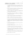
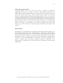
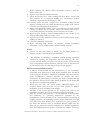
different wavelengths. These line spectra are characteristic for each element.
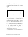
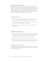
Sodium, for example, emits energy primarily at 589 nm, along with other; much
less intense emissions (refer the figure below.)). The wavelength to be used for
the measurement of an element depends on the selection of a line of sufficient
intensity to provide adequate sensitivity as well as freedom from other interfering
lines at or near the selected wavelength.
Alkali metals are comparatively easy to excite in the flame of an ordinary
laboratory burner. Lithium produces a red, sodium, a yellow, potassium a violet,
rubidium a red, and magnesium a blue color in a flame. These colors are
characteristic of the metal atoms that are present as cations in solution. Under
constant and controlled conditions, the light intensity of the characteristic
wavelength produced by each of the atoms is directly proportional to the number
of atoms that are emitting energy, which in turn is directly proportional to the
concentration of the substance of interest in the sample. Thus, flame photometry
lends itself well to direct concentration measurement of some metals.
Other cations, such as calcium, are less easily excited in the ordinary flame. In
these cases, the amount of light given off may not always provide adequate
sensitivity for analysis by flame emission methods. The sensitivity can be
improved slightly by using higher-temperature flames. Of the more easily excited
alkali metals like sodium, only 1 to 5 % of those atoms present in solution
become excited in a flame. Even with this small percentage of excited atoms, the
method has adequate sensitivity for measurement of alkali metals for most bio
analytical applications. Most other metal ions are not as easily excited in a flame,
and flame emission methods are not as applicable to their measurement.
Department of Biochemistry, Medical Research Institute, Colombo, WHO Biennium 2004-2005
27
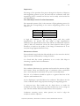
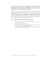
6s
5d
5s
4d
4p
4s
3d
3p
3p
3p
3s
Figure 1
Schematic diagram showing energy levels for certain lines of the sodium
spectrum. The major doublet at 589 nm (shown in heavy lines) results when the
excited valence electron returns from the 3p orbital to the ground state 3s orbital
5.1
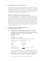
COMPONENTS OF FLAME PHOTOMETERS
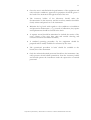
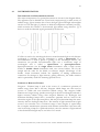
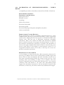
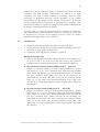
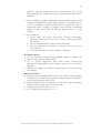
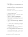
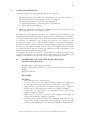
Figure 2 shows a schematic diagram of the basic parts of a flame
photometer. A cylinder of compressed gas and a two-stage pressure
regulator are required. High-pressure tubing must be used to lead the
gases to the flame. An atomizer is needed to spray the sample as fine
droplets into the flame. The monochromator, entrance and exit slits, and
detectors are similar to those discussed previously for
spectrophotometers. In effect, the light source for the spectrophotometer
has been replaced with an atomizer-flame combination, and one is
measuring emission of light rather than absorption.
Various combinations of gasses and oxidants have been proposed and are
being used in flame photometry. These include acetylene and oxygen for
the hottest flame, and natural gas, acetylene, and propane in combination
with either oxygen or compressed air. The choice of flame depends
largely on the temperature desired; for sodium and potassium
determinations, a propane- compressed air flame appears entirely
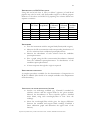
adequate. Typical flame temperatures are shown in the table below
The atomizer and the flame are critical components in a flame
photometer. The atomizer provides a means of drawing the sample
through the aspirator and converting it into a fine mist, which then enters
the flame. This can be done by passing a gas of high velocity over the
upper outlet of a capillary tube, the lower end of which is inserted into
the sample. Liquid is then drawn up into a chamber and dispersed into
small droplets. The larger droplets settle to the bottom and go to waste.
The most important variable in the flame itself is the temperature.
Frequent calibration of flame photometers is essential because thermal
changes do occur and affect the response of the instrument. In addition,
temperature changes affect the output of photocell detectors; for this
reason, a period of warm-up, with aspiration of distilled/ deionised water
and calibrators, is required before measurements are taken, in order to
establish thermal equilibrium for the flame and the atomizer chamber.
Department of Biochemistry, Medical Research Institute, Colombo, WHO Biennium 2004-2005
28
Ideally, monochromators in flame photometers should be of higher
quality than those found in absorption spectrophotometers. When
nonionic materials are burned, light of varying wavelength is given off.
This is known as continuous emission and will be added to the line emission of
the element being measured. For this reason, the narrowest band path
that is achievable should be used to eliminate as much of the extraneous,
continuous emission as possible, but still permit a maximum of the line
emission to pass through to the detector. The detectors used in flame
photometers operate by the same principle and in the same way as those
described for spectrophotometers.
In recent years, the argon inductively coupled plasma (ICP) torch has
become commercially available as an excitation source for emission
spectrophotometry. With this source, argon ions are inductively coupled
to a radiofrequency generator that serves as the means to excite ions and
molecules to energy states that will produce light emission.
A common design involves three concentric glass or quartz tubes
mounted with a radiofrequency (RF) coil wrapped around the outermost
tube. Liquid sample is aspirated up the innermost tube. With the middle
tube containing the argon gas fed in an upward direction. An RF
generator is set to produce a frequency at 27 MHz. At this frequency, the
argon gas is ionized, and the electron rich plasma in the outermost tube
inductively reacts with the magnetic field created by the RF coil. These
reactions produce a flame like torch that forms near the top of the
concentric tubes. The temperature in the flame reaches 5000 to 9000 0 C
and allows dissociation of many of the chemical complexes that cause
inaccuracies in flame photometry. This transfer of energy into the sample
then allows many of the chemical species in the torch to lose energy in
the form of emitted light and provide high resolution of the emitted lines
in a quality spectrometer.
Flame
Monochromator
Automizer
Entrance
Aspirator
Detector
Exit Slit
Figure 2 Essentials of a flame Photometer
Department of Biochemistry, Medical Research Institute, Colombo, WHO Biennium 2004-2005
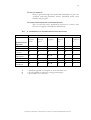
29
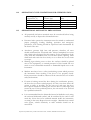
Flame Temperatures for Various Gas Mixtures
Gas Mixture
Natural gas – air
Propane – air
Hydrogen – air
Acetylene – air
Hydrogen – Oxygen
Natural gas – Oxygen
Propane – Oxygen
Acetylene - Oxygen
5.2
Flame Temperature 0C
1840
1925
2115
2250
2700
2800
2850
3110
DIRECT AND INTERNAL STANDARD FLAME PHOTOMETRY
In some of the instruments of earlier designs, calibrating solutions of
sodium or potassium were atomized or aspirated directly into the flame
to provide a series of meter readings against which an unknown solution
could be compared. This approach, referred to as the direct reading
method, presents certain problems:
1. Minor fluctuations in air or gas pressure cause unstable response
in the instrument and lead to errors
2. Separate analyses and sometimes separate dilutions must be made
for sodium and potassium.
3. The potassium signal is enhanced by the sodium concentration in
the specimen.
The latter effect known as mutual excitation, results from the transfer of
energy from an excited sodium atom to a potassium atom. Consequently,
more potassium atoms are excited and light emission is increased. Ideally,
then the concentration of sodium and potassium in the calibrators should
closely approximate those in the unknown, a situation that is difficult to
achieve when analyzing a sample such as urine in which these electrolytes
show wide variation in concentration.
In the internal standard method, lithium or cesium is added to all
calibrators, blanks, and unknowns in equal concentrations. Lithium has a
high-emission intensity, is normally absent from biological fluids, and
emits at a wavelength sufficiently removed from that of sodium or
potassium to permit spectral isolation. The flame photometer makes a
comparison of the emission of the desired element (sodium or potassium)
with the emission of the reference lithium element. By measuring the
ratios of emissions in this way, small variations in atomization rates,
flames stability, and solution viscosity are compensated for. Lithium does
not function as a calibrator under these conditions but as a reference
element. Variable concentrations of sodium and potassium, in the lithium
diluent, must be used to establish calibration curves or to verify linearity
of response.
Department of Biochemistry, Medical Research Institute, Colombo, WHO Biennium 2004-2005
30
Lithium also acts as a radiation buffer to minimize the effects of mutual
excitation. The final working concentration of lithium is so high,
compared with that of either sodium or potassium, that the same
percentage of potassium becomes excited regardless of the sodium
concentration in the sample. Serum lithium concentrations in patients
receiving lithium salts are maintained at approximately 1 mmol/L. This
amount will produce no significant change in final lithium concentrations
in samples containing lithium in the diluent.
A setting agent is frequently recommended for inclusion in calibrators
and sample dilutions. This minimizes changes in atomizer flow rates due
to differences in viscosity of the samples. Viscosity effects are further
reduced by diluting samples 100 to 200 fold.
5.3
CALIBRATION
Chemicals used for calibration should be of analytical grade
All the glassware should be thoroughly cleaned and finally rinsed with
deionised or good quality distilled water.
Volumetric flask and pipettes should be of grade A
REAGENT PREPARATION
Sodium chloride and Potassium chloride should be dried separately in
an oven at 1000 C for four hours and after drying, the chemicals
should be kept in separate desiccators to attain room temperature.
A. Stock Sodium Standard Solution 1000 mmol/L (Stock A)
Weigh out accurately 58.455 g of dried sodium chloride in a beaker
and transfer in to a 1 litre volumetric flask with deionised/distilled
water. Rinse the beaker with deionised/distilled water and transfer
into the volumetric flask. Make sure that all the chemicals are
transferred into the flask. Mix well to dissolve the chemical. Finally
make up to the mark with deionised/distilled water. Mix well.
Transfer in to a clean polypropylene bottle.( Prepare about 200 ml of
the solution)
B. Stock Potassium Solution 100 mmol/L
(Stock B)
Weigh out accurately 7.456 g of dried potassium chloride in a beaker
and transfer in to a 1 litre volumetric flask with deionised/ distilled
water. Rinse the beaker with deionised/distilled water and transfer
into the volumetric flask. Make sure that all the chemicals are
transferred into the flask. Mix well to dissolve the chemical. Finally
make up to the mark with deionised/distilled water. Mix well.
Transfer in to a clean polypropylene bottle.( Prepare about 100 ml.of
the solution)
Department of Biochemistry, Medical Research Institute, Colombo, WHO Biennium 2004-2005
31
C. Diluent Concentrate
Dilute 1 ml of ‘Corning 460/405 diluent concentrate’ to 1000 ml with
deionised/distilled water.
CALIBRATION
Preparation of working standard series
Pipette stocks solution A and B into six 100 ml volumetric flasks as
follows
1
2
Sodium concentration mmol/l
110 120
Potassium concentration mmol/l
2
3
Stock A (ml)
11
12
Stock B (ml)
2
3
Make up to 100 ml with distilled water. Mix well
3
130
4
13
4
4
140
5
14
5
5
150
6
15
6
6
160
8
16
8
An example of the calculation to prepare 100 ml of working standard
solution of Sodium 110 mmol/l and Potassium 2 mmol/l is as follows
C1V1 =
C1
C2
V2
C2V2
=1000 mmol/l
=110 mmol/l
=100 ml
1000 x V1
V1
=110 x 100
=11 ml
C1V1 =C2V2
C1
C2
V2
=100 mmol/l
=2 mmol/l
=100 ml
100 x V1
V1
= 2 x 100
= 2 ml
Add 11 ml of stock A solution and 2ml of stock B solution into a 100 ml
volumetric flask and make up to 100 ml with deionised/distilled water
Department of Biochemistry, Medical Research Institute, Colombo, WHO Biennium 2004-2005
32
Display value Display value PROCEDURE TO PREPARE THE CALIBRATION GRAPH
0.1 ml of each working standard should be added to 19.9 ml of
diluent in separate containers
Each diluted working standard solution should be aspirated into the
flame photometer for 20 seconds (starting with the lowest
concentration to avoid carry over) again allowing 10 seconds between
measurement and observe the readings.
Plot the graph using the concentration Vs readings and observe the
linearity.
Sodium concentration 5.4
Potassium concentration OPERATING PROCEDURE
The details of the operation procedure may vary from one instrument to
another. Following steps are related to ‘Corning 410’ clinical model flame
photometer, which is available in most hospital laboratories. Follow the
manufacturer’s manual.
1. Sample dilution: Dilute each serum, quality control sample and
working standard solution 1:200 with working diluent concentrate.
Into 50 ml conical flasks pipette 19.9 ml of working diluent
concentrate and add 0.1 ml of working standard solution/quality
control sample/ patient’s serum and mix well.
2. Turn on the fuel supply at source
3. Depress the ‘power’ switch to switch on the instrument 410. The
‘power on’ LED will be illuminated, the air compressor will start an
ignition cycle will commence.
4. If the flame on LED is not illuminated at the end of the ignition
cycle, (Refer the operator’s manual available with the instrument)
Check that the air pressure gauge indicates a reading between 11 and
13 psig. If it does not, lower the air regulator locking ring and adjust
the regulator for a reading of 12 psig on the air pressure gauge. Raise
the locking ring to lock the air regulator adjuster.
5. Set the filter selector to the required position. Non luminous blue
flame with distinct cones can be seen, if does not; adjust the fuel to
get distinct blue cone flame.
6. Insert the Nebulizer inlet tube in a beaker containing approximately
100 ml of diluent and allow 15 minutes for the operating temperature
to stabilize. This will ensure a stable burner temperature when
solutions are aspirated, after the warm up period.
Department of Biochemistry, Medical Research Institute, Colombo, WHO Biennium 2004-2005
33
7. While aspirating the diluent, adjust the ‘blank’ control so that the
display reads zero
8. Aspirate a pre diluted standard solution
9. Allow 20 seconds for a stable reading and then adjust ‘coarse’ and
‘fine’ controls for a convenient reading (if a 140 mmol/l Sodium
standard is aspirated, set the display to 140)
10. Carefully adjust the ‘fuel’ control for a maximum reading on the
display, ensuring that only small adjustments are made, with a pause
of several seconds between adjustments.
11. Remove the standard solution, wait 10 seconds, then aspirate a blank
solution of diluent for 20 seconds. Adjust the ‘blank’ control for a
zero reading. Remove the blank solution and wait 10 seconds.
12. Repeat steps 8, 9 and 11 until the blank reading is zero (within ± 0.2)
and the calibration reading is within ± 1%.
13. Aspirate each of the unknown solutions for 20 seconds, then note the
readings in mmol/l
14. Check the calibration frequently
15. When analyzing large batches of samples, recheck instrument
calibration every 10 samples with a single standard solution.
NOTE:
• Always use the same batch of diluent for the blank, dilution of
samples, quality control material and standards.
•
Any difficulty in obtaining a maximum sodium reading should be
rectified by opening the inspection flap and adjusting the ‘fuel’
control until the flame just starts to lift off the burner. Then turn the
‘fuel’ control back, counter clockwise, until the cones of the flame are
on the burner. Close the flap and proceed with paragraph 11.
PRECAUTIONS AND LIMITATIONS:
1. A diluent recommended by the manufacturer of the instrument
should be used. Deionised or high quality distilled water should be
used to prepare the diluent. Deionised or distilled water must be free
from contaminative elements (bacteria or moulds can cause
inaccuracies by interrupting or blocking the flow of sample through
the nebulizer. Always use the same batch of diluent for the blank and
the dilution of samples and standards.
2. Dilute the sera with care. Good quality calibrated pipette or a
sensitive diluter must be used. Use the same pipette or dilution
equipment for both standards and samples.
3. Accuracy of the results depends on the accuracy and purity of the
calibration standard. Always use accurately prepared standards.
4. Both the accuracy and precision of results depends on maintenance
and adherence to operating instructions provided by the
manufacturer. Careful cleaning of the atomizer-burner, cleanliness of
sample containers, the aspirating systems, proper adjustment of flame
size, (blue flame with distinct cone) aspiration rate, and geometry of
the flame and uniform entry of atomized, diluted sample into the
flame are also critical for accuracy and precision. Thermal equilibrium
must be established before analysis of unknown samples. Warm up
Department of Biochemistry, Medical Research Institute, Colombo, WHO Biennium 2004-2005
34
period is necessary because the initial evaporation of water in the
flame decreases the temperature of the burner and the entire burner
chamber.
5. Safety: Propane is highly inflammable and potentially explosive and
commonly supplied as a liquid under pressure in a cylinder for use
with the instrument. Cylinder should never be subjected to heat or
mechanical shock. Leakage of propane from the tank, instrument
fittings or from valves may be detected with the aid of a soap
solution.
6. Site conditions:
Never install the flame photometer beneath overhanging
cupboards. There must be at least 1 metre of clear space above
the chimney.
The environment must be clean and free from dust
The instrument must be placed on a strong, level work top, free
from vibration
Avoid the instrument to direct sunlight or draughts
ACCURACY CHECK
Set the instrument using Corning standard solution ( Sodium 140
mmol/l and potassium 5.00 mmol/l)
Use an assayed (Specimens with stated values) normal and
pathological range quality control samples. (process as for patients’
samples)
Observe the readings and calculate the percentage of inaccuracy using
the readings
PRECISION CHECK
Quality Control sample(Sodium around 140 mmol/l and potassium
5.0 mmol/l)or an accurately prepared standard solution is diluted as
in the given procedure can be used
Results obtained from 20 replicates of the same sample, aspirating
sample for 20 seconds, then 10 seconds of air.
Na (140 mmol/l) better than 1.5 % CV
K ( 5.0 mmol/l) better than 1.5 % CV
Department of Biochemistry, Medical Research Institute, Colombo, WHO Biennium 2004-2005
35
5.5
MAINTENANCE (CIBA-CORNING 410)
GENERAL
The daily, weekly, monthly and six-monthly maintenance should be
carried out by the technical staff/biomedical engineering staff...
Maintenance of the air compressor, dilutor and chart recorder, if used,
refer the instructions supplied with the equipment.
WARNING
The cleaning of component parts of the instrument such as the nebulizer,
mixing chamber, burner parts, drain tubing and drain vessels should be
carried out by using tubing disinfectant. The waste should be treated
with caution as it may contain pathogenic organisms.
DAILY MAINTENANCE
(PERFORMED BY LABORATORY TECHNICAL STAFF)
Equipment required: none
1. Empty waste container, if used.
2. Check air line for condensation, and drain if necessary
3. Check ‘U’ tube is filled with deionised water.
WEEKLY MAINTENANCE
Equipment required: 10 ml beaker; stop watch; nebulizer cleaning wire;
cleaning solution or deproteinizing solution for clinical applications;
stainless steel nebulizer tube and sleeve, or polythene inlet tube, as
required.
1. Carry out daily maintenance procedure
2. Deproteinising the system
3. Check the operation of the Nebulizer (only by Biomedical
Engineering staff)
MONTHLY MAINTENANCE
Equipment required: As for weekly maintenance
1. Carry out daily and weekly maintenance procedures.
2. Check the constant head drain, mixing chamber, ‘U’ tube and drain
tube and clean if necessary. Check that the ‘U’ tube is refilled with
deionised water on reassembly.
SIX-MONTHLY MAINTENANCE (BY BIOMEDICAL ENGINEERING
STAFF)
Equipment required: As for weekly maintenance, plus the following;
‘U’ tube and tube; methanol; tissues; soft lint free cloth; cotton buds.
1. Carry out the daily and weekly Maintenance procedures.
2. Clean the mixing chamber, burner tube, burner and constant head
drain
3. Replace stainless steel Nebulizer tube and sleeve, (or polythene
Nebulizer tube if fitted), ‘U’ tube and drain tube.
4. Clean the optical filters and the glass chimney
5. Check air and fuel tubing and connectors for leaks, using a soap
solution.
Department of Biochemistry, Medical Research Institute, Colombo, WHO Biennium 2004-2005
36
NEBULIZER
MAINTENANCE (SHOULD BE CARRIED
COMPETENT BIOMEDICAL ENGINEERING STAFF)
OUT
BY
Equipment required : Stop watch; 10 ml beaker; cleaning wire; cleaning
solution or deproteinising solution for clinical applications; stainless steel
Nebulizer tube and sleeve, or polythene inlet tube, as required,
OPERATIONAL CHECK
1. Turn off the fuel supply at source.
2. Switch on the 410 (and the air compressor, if it is not connected to
the “compressor” socket on the rear of the instrument). Check that
the “flame on” LED is off.
3. Fill the beaker with deionised water, and weigh it.
4. Present the 10 ml beaker of deionised water to the Nebulizer tube for
an accurately timed minute.
5. Reweigh the beaker and calculate the aspiration rate. If it is between 2
and 6 ml/minute, no further action is required. If it is too low,
continue with paragraph 6. If it is too high contact your Corning
Distributor. Do not attempt to adjust the Nebulizer, as the capillary
position is fixed during manufacture, and is not adjustable.
CLEANING THE NEBULIZER
6. Release the Nebulizer retainer and withdraw the Nebulizer
7. Remove the Nebulizer inlet tube and sleeve, from the Nebulizer. Pass
a cleaning wire through the Nebulizer inlet tube and the sleeve.
8. Inspect the end of the Nebulizer capillary and remove any blockages.
9. Insert a cleaning wire into the Nebulizer capillary.
10. Refit the Nebulizer inlet tube and sleeve to the Nebulizer. If difficulty
is experienced in cleaning the inlet tube and sleeve, fit new parts.
Recheck the aspiration rate, paragraph 3, 4 and 5.
11. If Nebulizer operation is still outside the specification, unscrew the
air line connector and remove the Nebulizer inlet tube and sleeve
from the Nebulizer.
12. Soak the Nebulizer in a 1 in 100 dilution of cleaning solution or
deproteinising solution for clinical applications, agitating it
periodically.
13. Rinse thoroughly in deionised water and shake dry.
14. Refit the Nebulizer inlet tube and sleeve and the air line. Recheck
aspiration rate.
15. If Nebulizer operation is still unsatisfactory, fit a new Nebulizer. Do
not attempt to adjust the Nebulizer, as the capillary position is fixed
during manufacture, and is not adjustable.
16. Fit the constant head drain to the spring clip and position it so that
the lip on the drain is resting on the spring clip.
17. Connect the fuel tubing to the mixing chamber and cap. Connect the
’U’ tube between the mixing chamber end cap and constant head
drain. Fit the drain tube to the constant head drain.
18. Fit the Nebulizer into the end cap and position the retainer to lock it.
19. Use a wash bottle to fill the ‘U’ tube with deionised water. Sufficient
water should be used to completely fill the ‘U’ tube and purge it of
air.
Department of Biochemistry, Medical Research Institute, Colombo, WHO Biennium 2004-2005
37
CLEANING THE OPTICAL FILTERS AND GLASS CHIMNEY (SHOULD
BE CARRIED OUT BY COMPETENT BIOMEDICAL ENGINEERING STAFF)
Equipment required: Soft, lint free cloth; methanol; cotton buds;
tissues; cleaning solution.
1. Check that the “flame on” LED is off, fuel is turned off at source,
and 410 is switched off.
Warning: Do not proceed until all the parts within the chimney are
at a safe handling temperature
2. Lift off the chimney cap from the chimney assembly. Lift out the
glass chimney.
3. Move the filter selector to the top position, and push the lever
upwards and to the right. This will disengage the filter selector from
the stop. Lift the filter selector out of the chimney.
4. Position the filter selector on the lint free cloth so that the colored
sides of the filters are uppermost and the thumb grip is at the top, as
shown in figure 3
Caution: Handle the optical filters only by the edges, “never” the
faces.
5. Using a soft probe, (cotton bud or similar), that will not scratch the
filters, push out the first filter. Examine the filter edges and note the
wavelength on figure 3, alongside the appropriate space. Remove the
remaining two filters and mark the wavelengths on figure 3
6. Carefully wipe each filter with a cotton bud soaked in methanol.
7. Turn the filter selector over so that the large holes and filter retainers
are uppermost.
8. Refer to figure 3 and carefully replace the filters, mirrored sides
upward, into their respective positions.
9. If a filter is being changed note the new wavelength on figure 3. Also
place the self-adhesive label (supplied with the filter) in the correct
position over the filter selector label already in place on the front of
the chimney assembly. The “top” filter, Na in figure 3, is the
“bottom” position on the filter selector label.
10. Refit the filter selector into position inside the chimney and slide it
fully in. Check that all three positions can be selected.
11. Soak the glass chimney in a 1 in 100 dilution of cleaning solution,
agitating it periodically.
12. Rinse the glass chimney thoroughly in deionised water and dry with
clean tissues.
13. Replace the glass chimney “with the clear strip at the bottom”. Make
sure the glass chimney is seated correctly and refit the chimney cap on
top of the chimney.
Department of Biochemistry, Medical Research Institute, Colombo, WHO Biennium 2004-2005
38
VOLTAGE
SELECTION AND FUSE REPLACEMENT (SHOULD BE
CARRIED OUT BY COMPETENT BIOMEDICAL ENGINEERING STAFF))
Equipment required ;fuses.
Warning: For continued protection against fire hazard use only the same type
and rating of fuse that was fitted originally to the 410 refer to instrument rear
panel.
1. Check that the “flame on” LED is off, fuel is turned off at source, and 410
are switched off.
2. Disconnect the a.c. supply lead form the a.c. supply socket.
3. Disconnect the a.c. supply lead from the “power” connector on the rear
panel.
4. Open the voltage selector compartment and withdraw the voltage selector,
item 1. To replace fuses continue with paragraph 5; to change the operating
voltage continue with paragraph 7.
5. Slide out the two fuse holders, item 2, and remove the fuses.
6. Replace any burned out fuses and slide in the fuse holders.
7. Replace the voltage selector so that the required voltage setting is visible
through the window of the compartment cover. Close the compartment
cover and refit the a.c supply lead.
Na
589 nm
K
768 nm
Standard filters
as supplied
Li
671 nm
Figure 3
DEPROTEINISING OR DISINFECTING PROCEDURE
NOTE: To deproteinise the system use deproteinising solution, and to
disinfect the system use tubing disinfectant.
Equipment required: Deproteinising solution or tubing disinfectant
1. Light the flame
2. Present a beaker of deproteinising solution or tubing disinfectant to
the Nebulizer for 10 minutes
3. After 10 minutes have elapsed. Replace the beaker of solution with a
beaker of deionised water. Flush the system for two minutes.
4. Shutdown the instrument
Department of Biochemistry, Medical Research Institute, Colombo, WHO Biennium 2004-2005
39
6.
THE MICROSCOPE
The microscope magnifies the image of objects that are invisible to
the unaided human eye
A compound light microscope is the commonest type used in clinical
laboratories. It consists of two lens systems to magnify the image. Each
lens has a different magnifying power. A compound light microscope
may have a single eye piece (monocular) or two eye pieces (binocular)
6.1
TYPES OF MICROSCOPY
LIGHT MICROSCOPY
Uses a beam of light to view specimens
BRIGHT FIELD MICROSCOPY
The field of view is brightly lit so that organisms and other structures are
visible against it because of their different densities. Single stain or
differential staining may be used depending on the properties of different
structures and organisms.
DARK FIELD MICROSCOPY
The field of view is dark and the organisms are illuminated. A special
condenser is used which causes light to reflect from the specimen at an
angle.
PHASE-CONTRAST MICROSCOPY
Phase- contrast microscopy is a contrast enhancing optical technique that
can be utilised to produce high contrast images of transparent specimens,
such as living cells, micro organisms and many other structures.
Special condensers and objectives are used to alter the phase relationships
of the light passing through the object and that passing around it
FLUORESCENCE MICROSCOPY
In fluorescence microscopy specimens are stained with fluorochromes /
flurochrome complexes. Light of high energy or short wavelengths (from
halogen lamps or mercury vapour lamps) is then used to excite molecules
within the specimen or dye molecule attached to it. These excited
molecules emit light of different wavelengths often of brilliant colours.
ELECTRON MICROSCOPY
Electron microscopes use a beam of highly energetic electrons to
examine objects on a very fine scale. This examination can yield the
following information.
TOPOGRAPHY: Surface features of an object, its texture; direct relation
between these features and material properties.
MORPHOLOGY: The shape and size of the particles making up the
object, direct relation between these structures and material properties.
Department of Biochemistry, Medical Research Institute, Colombo, WHO Biennium 2004-2005
40
COMPOSITION: The elements and compounds that the object is
composed of and the relative amounts of them; direct relationship
between composition and material properties
CRYSTALLOGRAPHIC INFORMATION: How the atoms are arranged in
the object; direct relation between the arrangements and material
properties.
6.2
PARTS OF A LIGHT MICROSCOPE
The main parts of the microscope are the eye-pieces, microscope tube,
nose piece, objective, mechanical stage, condenser, coarse and fine
focusing knobs, and light source.
EYE-PIECES
The specimen is viewed through the eye-piece. It has a lens which
magnifies the image formed by the objective. The magnifying power of
the eye-piece is in the range 5x - 20x. A movable pointer may be attached
to the inside of the eye-piece.
In binocular microscopes, the two eye-pieces can be moved closer or
farther apart to adjust for the distance between the eyes by pulling
pushing motion or by moving a knurled ring.
MICROSCOPE TUBE
The microscope tube is attached on top of the arm. It can be of the
monocular or binocular type. It supports the eye-piece on the upper end.
MECHANICAL TUBE LENGTH
Mechanical tube length is the distance between the place where the
objective is inserted and the top of the draw-tube into which the eyepieces fit
In modern microscopes it is not tubular; it contains prisms that bend the
light coming up, thus providing a comfortable viewing angle. In a
binocular tube, the light is also split and sent to both eye-pieces.
Do not interchange the objectives of two microscopes if the
specified mechanical tube length is different.
NOSE-PIECE
The nose-piece is attached under the arm of the microscope tube. The
nose-piece houses the objectives and rotates them. The objectives are
arranged in sequential order of their magnifying power, from lower to
higher. This helps to prevent the immersion oil from getting onto the
intermediate objectives.
Department of Biochemistry, Medical Research Institute, Colombo, WHO Biennium 2004-2005
41
OBJECTIVES
The image of the specimen first passes through the objective. Objectives
with magnifying powers 4x, 10x, 40x and 100x are commonly used. The
magnifying power is marked on the lens and is usually colour-coded for
easy identification.
THE 100X OBJECTIVE IS FOR OIL IMMERSION
The numerical aperture (NA) is the measure of light-gathering power of a
lens. The NA corresponding to the various magnifying powers of the
objective is:
Magnification
10x
40x
100x
Numerical aperture
0.25
0.65
1.25
A high NA indicates a high resolving power and thus useful
magnification. To provide the best image at high magnification,
immersion oil is placed between the slide and the oil immersion objective
(100x). Unlike air, immersion oil has the same refractive index as glass.
Therefore, it improves the quality of the image. If immersion oil is not
used, the image appears blurred or hazy.
MECHANICAL STAGE
The mechanical stage holds the slide and allows it to be moved to the left,
right, forward or backward by rotating the knobs.
It is fitted with fine vernier graduations as on a ruler. This helps in
relocating a specific field of examination.
CONDENSER
The condenser illuminates the specimen and controls the amount of light
and contrast. There are different types of condenser. Some condensers
have a rack-and pinion mechanism for up-and –down adjustment.
The NA of a condenser should be equal to or greater than that of the
objective with maximum NA.
An iris diaphragm is provided below the condenser. This adjusts the NA
of the condenser when using objectives having low magnifying power.
A swing-out type filter holder may be fitted above or under the
condenser. In some microscopes the filter holder may not be swing-out
type. The filter holder holds detachable filters when required.
Condenser centering screws, when present, are used to align the
condenser with the objective.
Department of Biochemistry, Medical Research Institute, Colombo, WHO Biennium 2004-2005
42
A condenser raising knob may be present (if centering screws are not
present) or the distance may be fixed
TWO-SIDED MIRROR
A mirror is the simplest illuminator. The two-sided mirror provides
necessary illumination through reflection of natural or artificial light. It
has two surfaces, one plain for artificial light and other concave for
natural light. It is supported on two sides by a fork fixed on a mount in a
way that permits free rotation.
A mirror is usually fitted on a mount or at the base of the
microscope.
BUILT-IN LIGHT SOURCES
An illuminator is built into the base of the microscope. A halogen bulb
provides the best illumination. On top of the illuminator is an in-built
filter holder to fit the filter of desired quality.
FILTERS
Blue filters are used to change the light from ordinary electric bulbs into a
more natural white light.
Neutral density filters are used to reduce brightness without changing the
colour of the background.
Green filters may be useful in some situations.
Blue/green filters are not recommended for Ziehl-Neelsen microscopy
as the acid fast bacilli stained in red may not be clearly visible
IMMERSION OIL
Immersion oil must be used with objectives having NA more than 1.0.
This increases the resolving power of the objective.
An immersion oil of medium viscosity and refractive index of 1.5 is
adequate. Any synthetic non-drying oil with a refractive index of 1.5 and/
or as recommended by the manufacturer should be used.
Cedar wood oil should not be used as it leaves a sticky residue on the
objective. If cedar wood oil is used, particular care then needs to be taken
to ensure that the objective is thoroughly and promptly cleaned with
xylene after each session of use. Petrol can be used in place of xylene for
cleaning if xylene is not available.
Liquid paraffin should not be used as it has a low refractive index which
produces an inferior image. It is also unsuitable for scanning specimens
for long periods, as is required for accurate microscopy
Department of Biochemistry, Medical Research Institute, Colombo, WHO Biennium 2004-2005
43
COARSE AND FINE FOCUSING KNOBS
The coarse and fine focusing knobs are used to change the distance
between the specimen slide and the objective. The coarse focusing knob
alters this distance rapidly and is used to bring the specimen into the field
of view using and objective having low magnification power. The fine
focusing knob changes the distance very slowly and permits better
viewing of the object. One revolution of the fine focusing knob should
generally move the mechanical stage by 100 µm. The movement should
be smooth and free from jerks
HALOGEN LAMP
Halogen lamps are low wattage, high intensity lamps and are the
preferred light source. They emit white light, with higher luminosity. The
halogen lamp has a compact filament and sustains a longer life. Though
costlier, halogen lamps have the fore mentioned advantages over tungsten
lamps
6.3
FUNCTIONING OF THE MICROSCOPE
There are three main optical pieces in the compound light microscope.
All three are essential for a sharp and clear image. These are:
Condenser
Objectives
Eye-pieces
The condenser illuminates the object by converging a parallel beam of
light on it from a built-in or natural source. The objective forms a
magnified inverted (upside down) image of the object. The eye-piece
magnifies the image formed by the objective. This image is formed below
the plane of the slide.
The total magnification of the microscope is the product of the
magnifying powers of the objective and the eye-piece.
For example, if the magnifying power of the eye-piece is 10x and that of
the objective is 100x, then the total magnification of the compound light
microscope is: 10x x 100x=1000 fold magnification.
Department of Biochemistry, Medical Research Institute, Colombo, WHO Biennium 2004-2005
44
ROUTINE OPERATION OF THE MICROSCOPE
Ensure that the voltage supply in the laboratory corresponds to that
permitted for the microscope; use a voltage protection device, if
necessary.
Turn on the light source of the microscope
With the light intensity knob, decrease the light while using the low
magnification objective.
Place a specimen slide on the stage. Make sure that the slide is not
placed upside down. Secure the slide to the slide holder of the
mechanical stage.
Rotate the nose-piece to the 10x objective, and raise the stage to its
maximum.
Move the stage with the adjustment knobs to bring the desired
section of the slide into the field of view
Focus the specimen under 10x objective using the coarse focusing
knob and lowering the stage. Always turn the stage up towards the
objectives while looking from the side and not through the eyepieces, so as to avoid turning it up too far and damaging the
objective. Only thereafter do the actual focusing, looking through the
eye-pieces, by lowering the stage away from the objectives.
Make sure the condenser is almost at its top position. Centre the
condenser using condenser centering screws if these are provided in
the microscope. For this take out one eye-piece and while looking
down the tube, close the iris diaphragm till only pin-hole remains.
Check if this is located in the centre of the tube.
Open the condenser iris diaphragm to 70%-80% to adjust the
contrast so that the field is evenly lighted
Many modern microscopes have pre-centered and fixed
condensers. In these no adjustments are required. To reduce glare
adjust the opening of the iris diaphragm
Department of Biochemistry, Medical Research Institute, Colombo, WHO Biennium 2004-2005
45
Adjust the inter - pupillary distance till the right and left images
become one
Focus the image with the right eye by looking into the right eye-piece
and turning the focusing knob
Focus the image with the left eye by looking into the left eye-piece by
turning the diopter ring
Put one drop of immersion oil on the specimen
Change to 100x objective
Increase the light by turning the intensity knob until a bright but
comfortable illumination is achieved
Focus the specimen by turning the fine focusing knob
When the reading/observation has been recorded, rotate the
objective away from the slide
Release the tension of the slide holder, and remove the slide.
Turn off the light
If immersion oil was used, wipe it from the objective with lens paper
or muslin cloth at the end of each session of use. In general, avoid
wiping the objective except when it seems to be dirty. This is
sufficient if good quality oil is used (use synthetic oil recommended
by the manufacturer)
Do not clean lenses frequently. This may cause scratching and
chipping of lenses.
Always keep the immersion oil bottle capped and free from dust and
debris
Use a dropper and not a glass rod to put immersion oil on the slides
without touching it
The cover slip should conform to the specifications for the objective
of the microscope. Most oil immersion objectives are corrected for
cover slip of 0.17 mm thickness.
Do not increase the intensity of the light source beyond the
maximum permitted value
Department of Biochemistry, Medical Research Institute, Colombo, WHO Biennium 2004-2005
46
Do not use bad quality facial tissue or coarse cloth to clean the lens as
the coarse fibres can scratch the surface of the lens
Never touch electric bulbs with bare fingers. Natural oil from the skin
may burn and darken its surface causing premature decrease in light
intensity. Use lens paper to hold the bulb when inserting it
Do not introduce bubbles into the immersion oil by stirring it, or
sucking or expelling the oil violently. A bubble under the objective
will cause glare and lower contrast, thus reducing the quality of the
image.
Do not use xylene (or petrol) excessively to clean the lens. Excess oil
can be usually wiped off with lens paper or muslin cloth. If good
quality immersion oil is used xylene is usually not needed. Avoid
using cedar wood oil.
Do not exchange objectives of two microscopes unless you are
certain that their mechanical tube length specifications are identical
Eye strain should not develop if the microscope is used properly.
Never adjust the stage upward while looking through the eye-piece.
It will cause the objective to push against the slide and may
damage it.
Only the 100% objective can be used for viewing under immersion
oil. All other lenses are to be used without immersion oil; keep
them dry and avoid applying oil or any liquid to these lenses
Department of Biochemistry, Medical Research Institute, Colombo, WHO Biennium 2004-2005
47
6.4
MAINTENANCE OF THE MICROSCOPE
NOTE: In all cases, the manufacturer’s manual should be consulted for
specific instructions.
INSTALLATION AND STORAGE
Install the microscope on a sturdy, level table. Equipment and
instruments which generate vibrations, such as centrifuges and
refrigerators, should not be placed on or near this table.
The height of the table should be convenient for the use. As and
alternative or in addition, and adjustable stool should be made
available to make microscopy comfortable. The table should be away
from water, sinks, and racks containing chemicals, to prevent damage
to the microscope from splashes or spills.
Always carry the microscope with one hand supporting the base and
the other hand around the arm.
Place the microscope in a location from which it need not be moved
frequently
Turn the nose-piece to the objective with lowest magnifying power
before removing the slide and when the microscope is not in use
If the microscope does not have a built-in light source then the table
should be placed near a window away from direct sunlight and
arrangements made for the provision of a lamp.
In so far as is possible, the microscopy room should be free from
dust and should not be damp.
If the microscope is to be used every day, do not remove it from the
site of installation, provided security is assured.
When the microscope is not in use, keep it covered with a polythene
or plastic cover and take necessary precautions against fungus.
Dust is the worst enemy of the microscope. Always keep the
microscope properly covered. Fungus is also a major problem.
Always keep the microscope in dry surroundings.
In humid areas, store the microscope every night in a cabinet fitted
with and electric bulb (5 W or 40 W). This is switched on at night to
reduce humidity.
Department of Biochemistry, Medical Research Institute, Colombo, WHO Biennium 2004-2005
48
If the microscope is used intermittently and requires storage for
prolonged periods, keep it in an air-tight plastic bag with about 100 g
of drying agent. Remember to regenerate/replace drying agents (silica
gel or dry rice) fortnightly or as needed.
If only a wooden box is available, keep the microscope in it with
some dry silica gel.
MAINTENANCE OF LENSES
Avoid collection of dust and immersion oil on the objectives and eyepieces by keeping the microscope covered. Do not allow immersion oil to
touch any of the objectives other than the oil immersion objective.
Always keep the eye-pieces in place to protect the inner surface of the
objective. Close the holes of missing objectives in the nose-piece by using
special caps that are provided, or by sealing with adhesive tape.
REMOVAL OF DUST FROM LENSES
Check for dust or dirt on the lenses (eye-pieces, objective, condenser and
illuminator lenses) if the image appears hazy or with black dots.
If the black dot moves when the eye-piece is rotated, this means that
the dust is on the eye-piece.
If the black dot moves when the slide moves then the dust is present
on the slide.
If these two are ruled out, presume that the dust is on the objective.
Dust on objectives shows as dots if it is inside. If the dust is outside
the objective it shows as a hazy image.
Do not remove the dust from the lenses by wiping these with a
cloth as this can scratch the lens and damage it permanently. Use
an airbrush or a camel-hair/artist’s brush.
Dust can be removed with a camel-hair/artist’s brush or by blowing air
over the lens with an airbrush. Dust on the inner surface of the objective
can be removed by using a soft camel-hair brush (artist’s brush)
REMOVAL OF OIL FROM LENSES
The presence of oil on the lenses produces a hazy image. The localization
of oil can be done by the same method as has been described above for
localization of dust.
Oil should be removed with the help of lens paper using lens
cleaning fluid as recommended by the manufacturer. This can be
applied gently with lens paper. Do not use force to remove oil as
this might result in scratches on the lens.
Department of Biochemistry, Medical Research Institute, Colombo, WHO Biennium 2004-2005
49
If the field of view is not clear despite cleaning, and the microscope
works well with another lens, then the lens has been permanently
damaged and must be repaired or replaced.
If the field of view is not clear even after changing the lenses(objective
and eye-piece) there is probably dirt or fungus on the tube prisms. These
can be checked by removing the eye-pieces, and examining the upper part
of the microscope tube with the light fully opens. Fungus is seen as
threads, dots or a woolly layer.
INSPECTION OF THE OBJECTIVE
.
Carefully unscrew the objective from the nose-piece.
Gently remove one eye-piece to use as a magnifier (or use a
magnifying glass)
Grasp the objective in one hand with the front lens face up.
Hold the eye-piece in the other hand with the top lens facing down.
Bring the eye-piece very close to your eye and focus on the objective.
Change the angle of the objective so that light can reflect off its
surface. The two lens surfaces will be about 2.5 cm apart. Try to
avoid letting them touch each other.
Inspect the objective for scratches, nicks, cracks, deterioration of seal
around the lens, or oil seepage into the lens.
MAINTENANCE OF MECHANICAL MOVING PARTS
Mechanical moving parts of the microscope may become too stiff or too
loose.
Stiffness is due to accumulation of dust or because the sliding channel
has become rough. This problem can be solved by cleaning, polishing and
lubricating the sliding channel and the rack and pinion. First remove the
dust with a camel-hair/artist’s brush or by blowing air; clean it with a
solvent such as petrol, polish with metal polish and apply high quality
silicone grease to lubricate the moving parts.
Stiff movements may also be due to mechanical bending of some part.
Rectify the fault or call the service engineer.
With the prolonged use, the up and down movement of the mechanical
stage becomes loose. The stage, therefore, slides down during
examination resulting in loss of focus. Adjust the tension with the tension
adjustment device as recommended by the manufacturer.
Department of Biochemistry, Medical Research Institute, Colombo, WHO Biennium 2004-2005
50
MAINTENANCE OF LIGHT SOURCE
The supply of voltage (110v or 220V) must always conform to that
specified for the microscope. Adequate number of spare bulbs and fuses
should be available. Do not touch the bulbs with bare hands. Provide
adequate ventilation to take care of heat generated by light. Provide
voltage protection, if necessary. Before switching the lamp on, adjust the
variable voltage regulator to minimum. Switch on the lamp and slowly
increase the voltage until the desired intensity is achieved.
DAILY MAINTENANCE
Bring the variable voltage regulator setting to the minimum before
turning off the lamp. Turn off the light source of the microscope.
Gently wipe the immersion oil off the objective, condenser and
mechanical stage with lens paper or muslin cloth.
Replace the cover of the microscope and take necessary precautions
against fungus.
MONTHLY MAINTENANCE
Use an air brush to blow away dust. Clean the objectives, eye-pieces,
and condenser with lens cleaning fluid. Do not put fluid directly on
the lenses; instead, apply it to the lens paper and then clean.
Remove the slide holder from the mechanical stage and clean.
With a tissue moistened with water, wipe the dust off the body of the
microscope and the window of the illuminator in the base of the unit.
MAINTENANCE EVERY SIX MONTHS
Thoroughly inspect, clean, and lubricate the microscope after consulting
the manufacturer’s manual. This should preferably be done by competent
biomedical engineering staff
Department of Biochemistry, Medical Research Institute, Colombo, WHO Biennium 2004-2005
51
7.
MANUAL PIPETTES
7.1
INTRODUCTION AND CLASSIFICATION
Manual pipettes are devices used for accurate volumetric measurements
and transfers.
Two categories of manual pipettes are defined.
I. Volumetric or Transfer
II. Graduated or measuring pipettes
VOLUMETRIC PIPETTES
These pipettes hold and deliver only the specific volume indicated at the
upper end of the pipette.
Either “to deliver” [TD] or “to contain” [TC]
VOLUMETRIC PIPETTES [TD]
Consist of a cylindrical bulb joined at both ends to narrower glass tubing.
A calibration mark is etched around the upper suction tube and the lower
delivery tube is drawn out to a graduated taper Specifications are
indicated on the pipette. A volumetric transfer pipette is calibrated to
deliver accurately a fixed volume of a dilute aqueous solution. (e.g.
standard, calibrator or non viscous sample)The TD pipettes are filled and
allowed to drain by gravity. The pipette must be held vertically and the
tip placed against the wall of the receiving container, but not touching the
liquid in it. The most commonly used sizes are 1, 2,3,4,5 and 10 ml.
VOLUMETRIC “TO DELIVER” [TD] / BLOW OUT PIPETTE
E.g. Ostwold - Foline
Similar to the volumetric pipettes but have their bulb closer to the
delivery tip. Commonly used sizes are 0.5, 1.0, 2.0 and 3.0 ml. These
pipettes are used for accurate measurement of viscous fluid (blood or
serum).Using of a pipette bulb the liquid is drawn in to the pipette and
the meniscus is read. The liquid is blown out of the pipette only after the
liquid has drain to the last drop in the delivery tip.
MEASURING PIPETTES [TD] OR GRADUATED PIPETTES
These are glass tubes of uniform diameter with a tapered delivery tip.
Graduations are marked at uniform intervals; these pipettes are used for
measurement of regents only and not recommended for measurement of
samples and calibrators.
MOHR TYPE PIPETTES
Mohr type pipette is calibrated between two marks on the stem. Solutions
are delivered between the desired marks. Pipette should be selected, so
that the greatest volume is used, therefore maximum accuracy will be
achieved. Mohr pipette is never used as a blow out type of pipette but
delivers only point to point.
Department of Biochemistry, Medical Research Institute, Colombo, WHO Biennium 2004-2005
52
SEROLOGICAL PIPETTES
‘TO DELIVER’ / BLOW OUT
The pipette is calibrated to the tip. Pipette is filled and allowed to drain
and the remaining fluid is blown out.
PIPETTE ‘TO CONTAIN’ [TC]
These are calibrated for the total volume of liquid held in the pipette and
must be washed out completely for delivery of the correct volume.
TECHNIQUE OF MANUAL PIPETTING
Before using a pipette, be sure that it is the correct size, clean, and inspect
the tip for any damages.
Place a rubber bulb on the stem of the pipette
An automatic pipette filler may be used
Lower the pipette in to the solution. Allow sufficient depth to fill the
pipette above the calibration mark.
Apply suction and fill the pipette above the calibration mark.
Hold the pipette vertically. The index finger is placed over the upper
opening of the pipette and the liquid is allowed to drain to the mark.
Excess fluid outside the pipette is drain in to the solution by touching
inner wall of the bottle.
Transfer the pipette to the receiving container. Drain the pipette
freely in a vertical position, and the tip against the side of the
container.
The pipette must be held in a vertical position when adjusting the
liquid level to the calibration line and during delivery. The lowest part
of the meniscus, when sighted at eye level should be in level with the
calibration line on the pipette
The pipette has been calibrated to deliver its specified volume in a
vertical position with a constant rate of delivery
Do not attempt to force the liquid from the pipette at a faster rate
than free drainage permits
When using volumetric pipettes the flow of the liquid should be
unrestricted and the tip should be touching the inclined surface of
the receiving container until 2 seconds after the liquid has ceased to
flow
Avoid air bubbles in the pipette
Department of Biochemistry, Medical Research Institute, Colombo, WHO Biennium 2004-2005
53
7.2
CALIBRATION OF PIPETTES
Gravimetric method by weighing the 20 pipettings of distilled water with
same pipette on a sensitive balance. (Please refer the procedure given for
micro pipette calibration)
7.3
SPECIFICATIONS
Volumetric glassware is grade A, B, and student grade. Accuracy of grade
A glassware meet or exceed the requirements specified by the National
Bureau of Standards. Volumetric glassware used in clinical chemistry
laboratory is made of borosilicate glass. This has a high degree of thermal
resistance. Commercial brands are known as Pyrex and Kimax [Kimble]
Corex brand glassware is a special alumina-silica glass strengthened
chemically
7.4
CLEANING
General laboratory use glassware should be rinsed with water and
immediately place in a large plastic measuring cylinder full of water.
Then soaked in a weak detergent solution [Teepol] for 2-3 hrs
Rinse with tap water for several times and then with distilled water.
Dry in an oven at 60 0C, or in an incubator
DIRTY GLASSWARE
Put in a cylinder filled with dichromate solution and leave overnight .Pour
the dichromate solution in to another cylinder. Rinse the pipette with
water and dry in an oven at 60 0 C
Department of Biochemistry, Medical Research Institute, Colombo, WHO Biennium 2004-2005
54
8.
MICRO PIPETTES
Micropipettes contain or deliver small volumes of liquid ranging from 1 to 1000
µl. The most common type of semi automated device that uses either air
displacement or positive displacement to dispense the contained fluid; some
models with digital volume adjustments are also available
There are many brands of air displacement pipettes, but all are piston operated
devices. A disposable and exchangeable polypropylene tip is attached to the
barrel, and liquid is drawn into and dispensed from this disposable tip. Some
instruments can automatically eject the used pipette tip and reload new one,
minimizing analytical contamination.
There are also several brands of positive – displacement pipettes available. The
capillary tips which may be made of siliconized glass, glass or plastic can be
reused. These devices are particularly useful for handling reagents that will react
with plastics. Positive displacement pipettors deliver liquids by means of a
Teflon-tipped plunger that fits snugly inside the capillary. Carryover liquid is
negligible in properly maintain instruments and in some instances a washing step
is used in between samples.
Air displacement micropipette may be used in either of two modes, the forward
mode or the reverse mode. The reverse mode is used with two- component
stroke mechanism system only. The precession of these devices in the forward
mode depends on the precise draining caused by the air pressure, and they are
relatively sensitive to the physical characteristics of the liquid being pipetted.
.Reverse mode operation on the other hand, is considerably less sensitive to the
type of the liquid being dispensed. In the forward mode the piston is depressed
to the first stop on a two –stroke device, the tip is placed in the liquid, and piston
is slowly allow to rise back to the original position. This fills the tip with
designated volume of liquid. The pipette tip is then drawn up the sidewall of the
vessel so that any adhering liquid is removed. If there are any extraneous droplets
the tip is wiped carefully with a lint free tissue, with care been taken not to
“wick” out any sample from the pipette tip. The tip is then placed on the wall of
the receiving vessel, and piston is depressed smoothly to the first stop on a two –
stroke device allowing the liquid to drain. Then one should allow one second to
elapse before depressing the piston to the second stop, blowing out the
remaining liquid. When the reverse mode is used the liquid is aspirated after
depressing to the second stop position. This overfills the pipette with sample. To
dispense the liquid one then depresses the piston to the first stop and removes it
after waiting one second.
Positive-displacement micropipettes are used in the same manner as forward
mode air-displacement devices. Again careful wiping of the tip is crucial in order
not to “wick” out a sample from the tip. The need for maintenance of the Teflon
tip cannot be over emphasized.
Department of Biochemistry, Medical Research Institute, Colombo, WHO Biennium 2004-2005
55
8.1
QUALITY CONTROL OF MICROPIPETTES
GENERAL
The accuracy and precision of each micropipette should be calibrated on
acquisition and monitored during the course of the year. The frequency
of calibration will depend on the amount of use. Heavily used devices
may need monthly calibration, whereas rarely use devices may need to be
checked on with once or twice per year. Manufacturers of newer
micropipettes are claiming two year calibration stability.
Routine Maintenance is critical. Air displacement pipettes have a fixed –
length that must be maintained. In addition, there are seals to prevent air
from leaking into the pipette when the piston is moved. These must be
greased to maintain proper operation. The manufacturer will provide
guidelines for performing this maintenance. Any worn part must be
replaced and devices that do not meet specifications for precision or
accuracy will generally require servicing by the manufacturer
Positively displacement pipettes in general require the similar
maintenance with regard to spring checks and replacement of Teflon tips.
Many of these devices also are supplied with a slide wire that is used to
quickly check the plunger setting. This device cannot be used in place of
routine performance checks. Follow the manufacturer guidelines.
QUALITY CONTROL VALIDATION
The primary method for calibration of micropipettes is gravimetric
technique. A secondary method is spectrophotometric procedure with
potassium dichromate. The later method is unacceptable for volumes of
less than 10 µl.
The following protocol describes the gravimetric method for calibration.
DETERMINING PERFORMANCE OF VOLUMETRIC EQUIPMENT
PRINCIPLE:
The procedure is based on determining the mass of water samples
delivered by the instrument. True mass and volume are then calculated,
based on the density of water at specific temperature and corrections for
air buoyancy.
Deliver a total of 20 distilled water samples into a covered weighing
vessel and weigh each sample after delivery. Thereafter calculate the mean
mass and the mean volume of the delivered sample. Determine the
inaccuracy and the imprecision with which the mean volume of the
volumetric equipment has been determined
When handling the vessel use a tweezer or another device so as not to
contaminate the outside of the vessel. (The manual volumetric
equipment should be rinsed before testing) (Air displacement
semiautomatic pipettes should be calibrated for forward and reverse
techniques separately.
Department of Biochemistry, Medical Research Institute, Colombo, WHO Biennium 2004-2005
56
Procedure
1. Place a small amount of distilled water in the weighing vessel to cover
the bottom and place a cap on vessel.
2. Open door of balance chamber, place weighing vessel on balance pan
and close the door of balance chamber.
3. Release the arrestment system. Take readout to zero (electronic
balance) or record readout value (mechanical balance)
4. Arrest balance; open balance door, retrieve weighing vessel. Aspirate
distilled water into the pipette; remove vessel cap, deliver the water
sample into the vessel and replace vessel cap. To avoid evaporation
the period with uncovered vessel should be as short as possible.
5. Place vessel on balance pan and close balance door. Release
arrestment system and record balance readout.
6. Repeat steps 2, 3, 4 and 5 until 20 samples have been weighed.
7. Measure and record the water temperature and the barometric air
pressure.
8. (The procedure can be adapted to minimize the handling of weighing
vessel by opening and closing the top lid of the balance.)
CALCULATIONS
1. Calculate the individual weighing result (Mi) by subtracting the tare
reading from the sample reading.
2. Calculate the mean mass (M) from the individual weighing results
(Mi):
M = Σ Mi
N
Where N = Number of weighings
3. Calculate the mean volume ( Vt ) of the water samples from the mean
mass (M) :
Vt= M x Z
Where Z = conversion factor (ml/g), incorporating the density of
water when buoyed in air, at the test temperature and air pressure.
Values of Z for water at various temperatures can be found in the
table below.
4. Calculate inaccuracy (Et) of the volumetric equipment as the
difference between the nominal volume (V0) and the calculated mean
volume (Vt) in percentage of nominal volume
Et = Vt – V0 x 100 %
V0
Department of Biochemistry, Medical Research Institute, Colombo, WHO Biennium 2004-2005
57
5. Calculate the within- run imprecision (Coefficient of variation, CV)
from the distribution of individual mass (Mi) about their mean (M)
CV= SD x 100 %
M
Where SD = standard deviation = {Σ (Mi – M) 2 }
N–1
N= number of weighings
RECORDING SCHEME FOR DETERMINING PERFORMANCE OF
VOLUMETRIC EQUIPMENT
Type of volumetric equipment
Temperature of distilled water
Barometric air pressure
1
2
3
4
5
6
7
8
9
:
:
:
10
11
12
13
14
15
16
Weight of
weighing
vessel and
Sample
Wight of
weighing
vessel
Mass of
sample
( Mi)
Mean mass (M)
= M = Σ Mi
N
Mean volume (Vt)
= Vt= M x Z
Inaccuracy (Et)
= Et = Vt – V0 x 100 %
V0
Standard deviation (SD)
= Σ (Mi – M) 2
N–1
Coefficient of variation (CV) = SD x 100 %
M
Comments (Compare with the factory performance given by the manufacturer)
Department of Biochemistry, Medical Research Institute, Colombo, WHO Biennium 2004-2005
17
18
19
20
58
Value for Z (µl/mg) or (ml/g), as a function of
water :i.e reciprocal of density
Air Pressure
Temperature C
600
640
680
800
853
907
80.0
85.3
90.7
15.0
1.0018 1.0018 1.0019
temperature and pressure, for distilled
720
960
96.0
1.0019
760
1013
101.3
1.0020
800
1067
106.7
1.0020
15.5
18
19
19
20
20
21
16.0
19
20
20
21
21
22
16.5
20
20
21
22
22
23
17.0
21
21
22
22
23
23
17.5
1.0022
1.0022
1.0023
1.0023
1.0024
1.0024
18.0
22
23
24
24
25
25
18.5
23
24
25
25
26
26
19.0
24
25
25
26
27
27
19.5
25
26
26
27
28
28
20.0
1.0026
1.0027
1.0027
1.0028
1.0029
1.0029
20.5
27
28
28
29
30
30
21.0
28
29
30
30
31
31
21.5
30
30
31
31
32
32
22.0
31
31
32
32
33
33
22.5
1.0032
1.0032
1.0033
1.0033
1.0034
1.0035
23.0
33
33
34
35
35
36
23.5
34
35
35
36
36
37
24.0
35
36
36
37
38
38
24.5
37
37
38
38
39
39
25.0
1.0038
1.0038
1.0039
1.0039
1.0040
1.0041
25.5
39
40
40
41
41
42
26.0
40
41
42
42
43
43
26.5
42
42
43
43
44
45
27.0
43
44
44
45
45
46
27.5
1.0044
1.0045
1.0046
1.0046
1.0047
1.0047
28.0
46
46
47
48
48
49
28.5
47
48
48
49
50
50
29.0
49
49
50
50
51
52
29.5
50
51
51
52
52
53
30.0
1.0052
1.0052
1.0053
1.0053
1.0054
1.0055
Department of Biochemistry, Medical Research Institute, Colombo, WHO Biennium 2004-2005
mmHg
Mbar
kPa
59
If the expected volume of water is not dispensed, readjust the instrument
and repeat the investigation. (The micropipettes are provided with tools
for adjustment of volume. However it should be carried out only by
competent technical/biomedical engineering staff.)
In hot climates and when controlling minute volumes, the evaporation of water
during the calibration procedure must be taken into account. The evaporation of
water during the calibration process is determined by weighing the vessel, already
containing a few milliliters of water. Thereafter the pipetting steps are simulated
exactly the same way but without delivering water. After this simulation the
container is weighed again and the difference of the weight corresponds to the
weight of water evaporated during the pipetting procedure. It must be added to
the total weight of water delivered in the calibration procedure.
8.2
METHOD OF USING AUTOMATIC FILLERS
1.
2.
3.
4.
Press the bulb with pressing the valve marked A to expel the air first
Fix the filler to the pipette
Insert the pipette into the solution
By pressing the valve S fill the pipette with the solution , aspirate the
solution to the level above the calibration mark
5. Adjust the solution up to the calibration mark by pressing the value E
then deliver the solution using the value
Department of Biochemistry, Medical Research Institute, Colombo, WHO Biennium 2004-2005
60
9.
ANALYTICAL BALANCE
Analytical balances are in principle divided into two groups
1. Mechanical balances on which the compensation of the load is done in a
mechanical manner by transferring or removal of weights
The mechanical balances can be further subdivided in
a. Substitution balances ( constant load one pan balances)
b. Equal- arm two pan balances.
2. Electronic balances on which the compensation of the load is done by an
electromagnetic force. No weights are used.
Prolonged use and improper operation can influence the performance of an
analytical balance concerning accuracy and precision. A calibration is mandatory
to achieve reliable measurements from an analytical balance. Information on how
to perform the calibration may perhaps be found in the manual of the
manufacturer. Some of the new electronic balances have internal calibration
procedures (built-in control), which can be performed by pressing a push-button,
but in most cases external weights are used, the mass of which are known. Ideally
the external weights that are used in the calibration should be traceable to the
national and international standard weights.
In principle the control of accuracy is performed by loading the balance with
weights of known mass to cover the entire measuring range of the balance. The
readings of the balance should be close to the mass of the weights used.
9.1
CALIBRATION OF THE ANALYTICAL BALANCE
APPARATUS AND MATERIALS
Weighing boats or appropriate containers
Weights (preferably traceable to national and international standard
weights)
Electronic balance
PROCEDURE
ACCURACY
1. Place the balance in a level position
2. Close the door(s) of the balance chamber. Release the arrestment
system and determine the zero point by turning the “zero knob”
3. Arrest balance, open the door of balance chamber, place a weight of
known mass on the pan and close the door of balance chamber.
4. Compensate the load, release the arrestment system. Record the
balance reading in a scheme
5. Repeat steps 2, 3 and 4 for all others of the weights in the weight set
and record the balance reading in a scheme.
6. Calculate the deviations between the measured mass and the true
mass of the weights. Determine the percentage of inaccuracy and
decide on any adjustments to be made by competent biomedical staff.
Department of Biochemistry, Medical Research Institute, Colombo, WHO Biennium 2004-2005
61
RECORDING SCHEME FOR ACCURACY
Load(g) Measured mass True mass Deviation
Calculation of percentage of inaccuracy = True mass – Measured mass x 100
(%)
True mass
Comments:
Department of Biochemistry, Medical Research Institute, Colombo, WHO Biennium 2004-2005
62
PRECISION
Perform a weighing 20 times of a selected weight. Between each weighing
the balance must be arrested and the weight removed from the pan.
Record the balance readings and calculate the mean and standard
deviation.
RECORDING SCHEME FOR PRECISION
N
1 2 3 4 5 6 7 8 9 10 11 12 13 14 15 16 17 18 19 20
Mass
of
weight
0.5 g
Mi
Mean mass (m)
= ΣMi
N
Standard deviation
= Σ (Mi – m) 2
N-1
Coefficient of variation (CV) = Standard Deviation x 100
Mean Mass
Comments:
Department of Biochemistry, Medical Research Institute, Colombo, WHO Biennium 2004-2005
63
9.2
USE OF BALANCES
Choose a balance appropriate for the range of the object to be
weighed and the precision of a particular analysis
Prior to use, the balance should be checked for spilled substances and
spilled solids should be brushed away..
Ensure that the balance is leveled, on a stable surface.
Place the balance away from air currents.
The pan of balance should be checked to ensure that it is properly
seated on the pan mechanism.
Turn on the balance. If an error message is received in lieu of the tare
value, notify your supervisor immediately.
Press the tare button and wait until a stable zero point reading is
obtained. Re-press the tare button if necessary.
Select the range by pressing the control bar until the balance displays
mg (mg=range)
Releasing and then briefly pressing the control bar again, allow you to
switch between the 30 g range and the 160 g weighing range.
When the desired weighing range has been selected, wait: Display “---“, then 0.0000. The balance is now in the weighing mode.
Place the object to be weighed on the pan, in the centre area.
Allow the reading to stabilize and record the weight
If a container or weighing paper is to be used, press the tare
button and wait until a stable zero point reading is obtained. Add
the substance to be weighed, allow the reading to stabilize, and
record the weight.
Allow samples/ containers to reach room temperature before
weighing. Hot samples will generate an upward convection of warm
air that will cause an inaccurate reading.
Samples that are extremely hygroscopic or lose water rapidly must be
weighed in a closed container.
Department of Biochemistry, Medical Research Institute, Colombo, WHO Biennium 2004-2005
64
Volatile liquids must be weighed in a closed container or with a
trapping solvent.
“Lumps” are often caused by moisture or electrostatic charge and
may not constitute a representative sample.
When weighing a sample or reagent, discard excess material that has
been removed from the original container. Do not return material to
its original container.
Do not use regular paper for weighing. Use weighing boats or an
appropriate container.
Do not weigh containers containing a magnetic stir bar. The magnetic
field generated may cause unpredictable effects on the electronic
balance.
Fingerprints may cause an inaccurate value. Make sure hands are
clean and dry and do not contribute to the weighing.
Be sure to use a clean and dry spatula or other transfer device to
avoid contamination of the article to be weighed
A brush designed for the purpose can be used to eliminate
electrostatic charge on the balance pan. Do not weigh objects that can
carry an electrostatic charge, such as some plastics. Changed materials
can result in unpredictable balance behavior and weighing.
Turn off balance. Wash and replace spatula in the rack. Clean up any
rubbish or spillages near or on balance, close balance doors.
SPECIFICATIONS OF AN ANALYTICAL BALANCE
− Specify the type of balance required : Analytical balance
− State the purpose :To weigh chemicals and stains
− Range of weighing :
− Performance: State the required sensitivity (0.001g) will be
adequate in most situations.
− Pan size
− Power source: State the available power source and request
for a voltage stabilizer.
− Digital display
− Accessories; calibration weights and dust covers.
− Durability and robustness: Should be movable and be easily
disassembled and reassembled.
Department of Biochemistry, Medical Research Institute, Colombo, WHO Biennium 2004-2005
65
10.
CENTRIFUGE
10.1
INTRODUCTION
Centrifuges are used in the clinical laboratory to separate substances of
significantly different masses or densities. The two substances to be
separated can be a solid (particles) and a liquid or two liquids of different
densities.
In a clinical chemistry laboratory the centrifuges are used primarily to
separate clotted blood or cells from serum or plasma and body fluids.
Although the choice of a specific relative centrifugal force (RCF) to carry
out these separations is not critical, a force of 1000 to 1200 x g for 10 to
15 minutes is recommended. In some situations more time may be
necessary.
Three general types of centrifuges are available
•
•
•
Swinging bucket or horizontal head centrifuge
Fixed angle or angle head centrifuge
Ultracentrifuge
All centrifuges have a motor, drive shaft, and head or rotor, which may
be in the form of a chamber with a cover. A power switch, timer, speed
control, tachometer and brake are the components that control the
centrifuge. When necessary, refrigeration units are included. Some
centrifuges are equipped with an alarm that sounds when there is a
malfunction such as a tube imbalance. Some centrifuges automatically
shut down, preventing tube breakage and potential for exposure to bio
hazardous agents. All modern centrifuges have a safety latch that prevents
the operator from opening the instrument before the rotor has stopped.
The swinging bucket or horizontal head rotors hold the tubes in a vertical
position when the centrifuge is at rest. This type use pairs of buckets or
carriers that swing freely. The carriers are designed to accept a variety of
cushioned inserts allowing centrifugation of small tubes or large bottles.
The tubes move to and remain in horizontal position when the rotor is in
motion. During centrifugation, particles constantly move along the tube
while it is in the horizontal position, distributing the sediment uniformly
against the bottom of the tube. After centrifugation is complete and the
rotor has ceased turning, the surface of the sediment is flat with a column
of liquid above it.
Fixed angle rotors keep the tubes at a specified angle, 25 to 52 degrees to
the vertical axis of rotation. Different fixed angle rotors are required for
different sized containers. During centrifugation, particles move along the
side of the tube to form sediment that packs against the side and bottom
Department of Biochemistry, Medical Research Institute, Colombo, WHO Biennium 2004-2005
66
of the tube. The surface of the sediment in this case is parallel to the shaft
of the centrifuge. As the rotor slows and then stops gravity may cause the
sediment to slide down the tube forming a poorly packed pellet. Fixed
angle rotors are used when rapid sedimentation of small particles are
required. The design of these rotors is more aerodynamic, operation at
speeds higher than those achievable with a swinging bucket rotor. RCF
up to 14000 x g is achievable.
Ultracentrifuges are high speed centrifuges that use fixed angle or
swinging bucket rotors. They are often refrigerated to counter the heat
generated as a result of friction. This type is used to fractionate
lipoproteins, perform drug binding assays and prepare tissue for hormone
receptor assays. Analytical ultra centrifuges are used to determine
sedimentation coefficients of proteins, allowing assessment of molecular
weights.
The motor in a large centrifuge is usually a direct current, heavy duty
electric motor. In smaller centrifuges the current is usually alternating.
Power is transmitted to the rotor by the commutator and brushes. The
rotor shaft is usually driven by a gyro system and the bearings are sealed,
minimizing vibration and lubrication. Centrifuge speed is controlled by a
potentiometer that modulates the voltage that is supplied to the motor.
Speed is also determined by the mass of the load in the rotor. The
tachometer measures rotor speed in rpm. The brake decelerates the rotor
by reversing the polarity of the current to the motor. The timer permits
the rotor to reach a pre programmed speed. The rotor then decelerates
with out braking after a set time has elapsed.
Refrigerated centrifuges are used when the heat generated during
centrifugation could cause evaporation or denaturation of protein or
leakage of cellular components in the sample. The temperature can be
controlled between – 15 and 25 0 C, allowing centrifugation at higher
speeds for prolonged periods.
The selection of centrifuge tubes and bottles is important. Tubes with
tapered bottoms, which form more compact pellets, may be required
under certain conditions such as preparing urine sediment for
microscopic analysis. The tubes must fit snugly in the carriers the top of
the tube must not protrude so far above the carrier that the rotor is
impeded.
Balancing the tubes within the carriers is critical. All tubes should be filled
with an equal amount of liquid by weighing the two sets of carriers in a
two pan balance. In a situation where the tubes are unequal, dummy
tubes should be included with distilled water or a comparative liquid.
Each bucket should be balanced with respect to its pivotal axis. Improper
balancing can cause the centrifuge to vibrate, disrupting the formed
pellet. Bio hazardous material should be centrifuged with the caps or
stoppers in place to minimise aerosols.
Department of Biochemistry, Medical Research Institute, Colombo, WHO Biennium 2004-2005
67
10.2
CARE, MAINTENANCE AND QUALITY ASSURANCE
Always follow the manufacturer’s instructions for installation,
operation, cleaning, maintenance, lubrication, repair and replacement.
The instrument must be positioned exactly horizontally to prevent the
instrument moving away from its place during centrifugation.
Check if the rubber buffers/cushions are in the buckets.
Balance the tubes and buckets in the centrifuge.
Turn the speed control slowly to the required speed. Do not use the
centrifuge at a higher than necessary.
Daily cleaning of the centrifuge buckets with a non corrosive
disinfectant is recommended. The buckets should be inverted to drain
dry.
After any sample spillage wipe and disinfect immediately.
When tube breakage occurs remove the broken pieces using forceps
and thick gloves and dispose appropriately. The portions of the
centrifuge in contact with the blood or potentially infectious agent
must be immediately decontaminated. The centrifuge bowl should be
cleaned with a disinfectant, and rotor heads and buckets should be
autoclaved.
Stop the centrifuge immediately if it develops an abnormal sound
during operation.
Preventive maintenance should be carried out by trained biomedical
staff, on centrifuge speed using a tachometer every 6 months. The
measured and rated speed should not differ by more than 5% under
specified conditions. The accuracy of the centrifuge timer should be
checked every 6 months. The temperature of the centrifuge should be
checked at least monthly under standardized conditions. The
agreement between the measured and expected temperature should
be within 20C.Check brushes and bearings every 3 months. Replace if
necessary. Check for corrosion and repaint if necessary.
All maintenance function checks must be recorded, and all corrective
actions documented.
Department of Biochemistry, Medical Research Institute, Colombo, WHO Biennium 2004-2005
68
10.3
SPECIFICATIONS
Facts to be considered when writing up specifications and during
an evaluation of quotations for a centrifuge
Specifications should be written according your intended purpose of the
equipment.
Decide on the type (swinging bucket/fixed angle/ultracentrifuge),
capacity, table top/floor model, refrigerated or not (temperature range),
maximum relative centrifugal force, variable speed and time control
facility, bucket adaptor sizes, lid safety lock, availability of spare parts,
power and voltage requirement, guarantee of replacement of the
equipment due to mechanical failure in the first year, unit price with
accessories and total price with accessories, In the specification include
the phrase “complete functioning unit of a centrifuge” there by the
supplier is required to suggest any other requirement to be fulfilled for
the satisfactory functioning equipment. Include the purpose of the
centrifuge especially when the specifications are written for an
ultracentrifuge
When evaluating the quotations list your requirements and match with
the features given in the quotations. Give reasons for acceptance and
rejections. Valid technical reasons are required to justify the selection.
Department of Biochemistry, Medical Research Institute, Colombo, WHO Biennium 2004-2005
69
11.
AUTOCLAVE
11.1
INTRODUCTION
An autoclave in a clinical chemistry laboratory is used mainly for
sterilization of dirty glassware, instruments and material to be discarded.
In a microbiology laboratory the main purpose is to sterilize the
instruments, media and clean glassware. It is recommended to install two
autoclaves in a microbiology laboratory to carryout the sterilization of
‘’dirty glassware’’ and ‘’clean glassware’’ separately
Autoclave that uses saturated steam under pressure is one of the most
reliable methods available in the laboratory for the inactivation of all
forms of microbial life. To ensure safety and quality control, all bio
hazardous materials and items contaminated with potentially infectious
agents should be decontaminated before use or disposal. Such items
include laboratory equipment, glassware, and biomedical waste including
sharps. Steam sterilization is not recommended for anhydrous substances,
flammable materials, electrical equipment, radioactive material, or any
item that may be damaged in the autoclaving process.
The most common steam sterilizer found in laboratories is the gravity
displacement type.
Saturated steam enters the top of the chamber by a steam pressure
control valve. As the steam enters, it pushes the air out through a trap in
the drain line. Once all the air is evacuated, the trap closes. Steam
continues to fill the chamber of the autoclave until a preset temperature
and pressure is reached. The operating conditions are 1210C and 15
pounds per square inch gauge pressure.
The sterilization procedure consists of three phases, namely heat-up time,
the contact time, and the cool-down time. Once the temperature has
come to equilibrium, a minimum of twenty minutes contact time for all
surfaces that require sterilization is necessary to ensure complete
biological inactivation. Usually the heat-up time section of the
sterilization procedure is the time given for the chamber to heat up to the
prescribed temperature; therefore, the run time used must be long
enough for the entire package to equilibrate at 1210 C and still give the
load a twenty minute contact time.
Department of Biochemistry, Medical Research Institute, Colombo, WHO Biennium 2004-2005
70
11.2
OPERATING CYCLE CONDITIONS FOR STERILIZATION
Sterilizing
temperature(0 C)
115
122
128
136
11.3
Approximate
pressure (bar)
0.75
1.15
1.50
2.25
Maximum hold time
(min)
30
15
10
03
OPERATIONAL AND SAFETY PRECAUTIONS
All potentially infectious materials must be autoclaved before being
washed, stored, or disposed as biomedical waste.
Personnel who operate the instrument must be trained to understand
proper packaging, loading, labelling, operation and emergency
procedures. This training should be supervised and documented by
the head of the unit.
Autoclaves generate high heat and pressure; therefore, all users
should understand the associated risks. Always manipulate hot items
with a thick glove designed for this purpose. At the completion of the
cycle, allow the instrument unit to cool down before opening. Then
stand back and crack the door slowly so as to allow the excess steam
to escape.
Warning signs alerting users to these hot surfaces should be placed
next to the equipment, to remind personnel of this hazard. Do not
stack or store combustible materials or flammable liquids next to the
instrument.
Modern autoclaves have a safety interlocking system which prevents
the instrument from working if the door is not properly closed.
Extra precautions should be observed if the autoclave has no in built
safety mechanisms.
If steam is leaking around the door during the sterilization process,
the door has not been sealed properly. In this event shut down the
system as safely as possible. Let the unit cool, and reset the door.
Give special attention to making sure that the door is sealed tight, and
restart the run. If this problem persists, the unit needs to be serviced
by a qualified technician.
It is recommended that the biomedical waste be labelled as such using
the universal biohazard symbol, and be sterilized by the end of each
work day. Never leave non sterilized material inside the instrument,
or sitting in the waste disposal room overnight. Materials that contain
toxic agents, volatile chemicals, or radio nuclides should not be
autoclaved.
Department of Biochemistry, Medical Research Institute, Colombo, WHO Biennium 2004-2005
71
All biomedical waste that is to be autoclaved must be first placed in a
labelled autoclave bag. Sharps such as needles and scalpels must be
placed in a labelled and ridged sharps container before sterilizing. Do
not place sharp pipettes or broken glass in bags. These waste items
should go into boxes or pails to be autoclaved, or be sterilized using a
liquid sterilizing agent such as 10% sodium hypochlorite.
Biomedical waste that is to be sterilized in a chamber of an autoclave
must have an indicator that demonstrates that the waste has been
autoclaved before it can be disposed. It is recommended that
potentially infectious waste must be labelled “BIOHAZARD”, and
has the biohazard label present on the container.
Proper use of autoclave bags is necessary. Approximately 50 ml – 100
ml of water should be placed in the bag prior to the start to facilitate
steam production. If this water is naturally occurring in the load,
additional water will not need to be added. The bags should be
properly wrapped to prevent spillage. If the tape is wrapped too tight,
steam pressure can build up inside the bag causing it to rupture.
Do not overfill bags or the unit, as this may interfere with the
sterilization process due to poor steam circulation. The autoclave
bags should be placed on stainless steel trays.
Do not fill the container more than 75 percent capacity when
autoclaving liquids. This will ensure that the fluid has room for
expansion when heated. Since sterilizing liquids using steam can be
problematic, it is best to sterilize liquid waste using a chemical agent if
possible.
If liquid is being autoclaved borosilicate glass (Pyrex) or
polypropylene containers should be used. Loosen the caps on the
vessels to allow for pressure build up during the process. Always
place loose glassware and liquid containers inside a secondary
container during the autoclaving process.
Wear thick heat resistant gloves, splash goggles, and a rubber apron
to remove liquids from the autoclave.
The exhaust cycle must be set very slow for liquid loads. This allows
time for the liquid to cool below 100 0 C so the liquid does not boil as
pressure is reduced. Upon the completion of the run, open the door
slowly and stand back until the steam has cleared.
The parameters for the sterilization cycle will depend upon the
amount and type of material. . The exact operating procedure for
each model and various loads will differ; therefore, it is recommended
to write your own Standard Operating Procedure (SOP) for the steam
sterilization This SOP should include the sterilization procedure for
each type of load, amount, run and program. An autoclave log book
Department of Biochemistry, Medical Research Institute, Colombo, WHO Biennium 2004-2005
72
should be maintained including the date, time, type of load and
operator’s name
11.4
Each autoclave unit should have preventive maintenance, including
autoclave spore testing procedures and the responsibility should be
given to a qualified repair technician.
Operator preventive includes removal and cleaning of the drain
strainer, if applicable once a week and monthly visually inspecting the
autoclave gaskets, doors, shelves and walls for residue building and
wear.
Quality control monitoring program should be implemented and
visible indicators should be included in all autoclave runs Biological
indicators use heat resistant Bacillus stearothermophilus spores as a
control to test for an effective kill during the process. Spore vials are
placed in a challenging location in a medical waste bag during a run. A
negative growth demonstrates that the equipment is working
properly. If the tester obtains a positive growth, try the run again with
a fresh vial. Consistent positive growth indicates a problem that must
be repaired before the instrument can continue in service.
SPECIFICATIONS
IMPORTANT
FEATURES TO BE INCLUDED IN SPECIFICATIONS OF AN
AUTOCLAVE
Capacity: The size and capacity of the autoclave will depend on the
volume of work carried out. The chamber capacity should not be
larger than required. Calculate the capacity using the following
formula
Necessary capacity (litres) = Average daily work load (litres) x 1.5
Daily number of cycles
Spare parts: A set of spare parts should be included in the
specifications
Performance and safety: interlocking safety device on the door or lid
to prevent opening until the pressure has returned to atmospheric.
Maintenance
Heat source
Power source
Training
Quality control method for testing performance of the autoclave
should be included.
Department of Biochemistry, Medical Research Institute, Colombo, WHO Biennium 2004-2005
73
12.
REFRIGERATOR
12.1
INTRODUCTION
Refrigerators provide storage facilities for reagents and specimens.
Laboratory refrigerators must have a temperature monitoring system. For
refrigeration, the heat flow, which is normally transmitted from a warm
object to a cold object, needs to be reversed. Heat can be reversely
transmitted by evaporation and condensation of a liquid. The evaporation
of a liquid consumes energy to overcome the cohesion forces of the
molecules in the liquid state. This energy is called “latent heat”. The
absorption of latent heat by surrounding environment causes a drop in
temperature. Conversely, during condensation the latent heat of the
gaseous phase is available to increase the temperature.
Refrigeration makes use of energy absorbed by evaporation and
condensation of liquids that have a boiling point below room temperature
at atmospheric pressure. CF2CCl2 (boiling point: -30oC) and ammonia
(boiling point: -33oC) are commonly used as refrigerants. The liquid is
circulated through a closed pipe system, where on one side it is vaporized
(refrigeration chamber) and on the other side (outside the refrigeration
chamber) it is condensed.
Refrigerators are constructed upon two principles for condensation,
either absorption or compression.
The absorption principle is used in smaller refrigerators. The closed
system consists of an evaporator and absorption vessel, a heating
chamber and a condenser. Absorption refrigerators have a circuit
containing a constant pressure.
The three materials used in this system are water, ammonia and hydrogen
and cooling is achieved on the basis of
-
The capacity of water to absorb large quantities of ammonia
vapour
The fact that ammonia will evaporate from this solution if heat is
applied.
The laws of partial pressure which show that in a space occupied
by a mixture of a vapour and a gas, which do not react together
chemically, each component exerts the pressure which it would
produce if it alone occupied the said space. Therefore, the total
pressure is the sum of these two pressures.
A water/ammonia solution flows by gravity from the absorption vessel to
the heating chamber. The heating chamber is heated by an electrical
heating system. The heated water/ammonia solution releases water and
ammonia as a vapour. A water separator prevents drops of water from
moving ahead and the water is returned to the absorbed vessel, while the
light ammonia vapour enters the condenser. In the condenser, the
ammonia vapour is cooled and the ammonia moves by gravity into the
Department of Biochemistry, Medical Research Institute, Colombo, WHO Biennium 2004-2005
74
evaporation chamber. The evaporation chamber is fed with hydrogen gas,
which facilitates the evaporation of ammonia. During evaporation of the
ammonia latent heat is absorbed so that the temperature drops in the
compartment. The ammonia vapour is absorbed by the weak ammonia
solution in the absorption vessel where heat is liberated and removed by
air-cooled fins. A concentrated ammonia solution flows again by gravity
to the boiler, where the cycle is repeated.
A compression system, which is used for cold rooms and also for small
refrigerators, consists of an evaporator, an expansion valve or throttle
pipe, a condenser and a compressor.
The refrigerant liquid evaporates in the evaporator, which is placed in the
refrigeration chamber, and enters into the compression chamber, where it
is compressed. The compression warms the vapour, and the higher
pressure raises the boiling point if the refrigerant. When leaving the
compressor at elevated pressure the vapour passes the condenser and
condenses to liquid while cooling. The liquid flows through a capillary
after which it is exposed to low pressure which reduces the boiling
pressure, thus resulting in evaporation. This process requires energy and
latent heat from the refrigerant, thus the temperature of the refrigerant
drops below room temperature.
Some refrigerators have two condensers, one for cooling the refrigerant,
the other for cooling the oil in the compressor.
12.2
MAINTENANCE OF REFRIGERATORS
GENERAL MAINTENANCE:
- Refrigerator must be placed so that sufficient air can pass the
condenser (at the back of the refrigerator) for exchange of heat
and also to facilitate cleaning of the condenser.
- The refrigerator door must seal perfectly to prevent warm outside
air from entering the cool chamber.
- The refrigerator must have good insulating walls.
DAILY CHECKS
- Check temperature daily. It should not exceed 12oC. Application
of battery-driven mobile or stationery thermometers are
recommended, preferably those including continuous printing or
plotting of temperature measured when heat-sensitive reagents
are stored for long periods.
MONTHLY CHECKS
- Clean cool chamber and defrost the evaporator monthly
- Clean refrigerator from the outside.
- Clean condenser for dust
Department of Biochemistry, Medical Research Institute, Colombo, WHO Biennium 2004-2005
75
TEMPERATURE CHART
REFRIGERATOR - LAB ………..
MONTH ……………………………
Date
Time
SERIAL NO………….
YEAR…………………
Refrigerator Freezer
Comments M.L.T
Temperature Temperature
Department of Biochemistry, Medical Research Institute, Colombo, WHO Biennium 2004-2005
76
12.3
SPECIFICATIONS
Storage capacity: This is influenced by the availability of other
refrigerators and the type and size of
the laboratory.
Refrigerator capacity between 75 and 120 litres with a
freezer capacity of between 3 and 5 litres is
recommended
Performance : refrigerator temperature
Freezer temperature
Principle :absorption /compression
Compression refrigerators are preferred as the
thermostat ensures correct temperatures and requires
less energy.
100% CFC (chlorofluorocarbon ) free model
Non frost preferred
Power
Upright refrigerator
Refrigerator thermometer should be included
Sample storage refrigerators are available with specially designed
racks. Location of the sample is made easier with the assigned rack
number/row number/column number.
00 C to 8 0 C range
-15 0 C to - 30 0 C range
Department of Biochemistry, Medical Research Institute, Colombo, WHO Biennium 2004-2005
77
13.
FREEZERS
Freezes are required in clinical chemistry to store body fluids which are heat
labile (hormones) and for long term storage of samples.
13.1
SPECIFICATIONS
Capacity ; depends on the requirement of the laboratory
Interior and exterior dimensions
Temperature : - 150 C to -250 C
Sufficient for storage of samples for one month
Ultra low freezers - 80 0 C
Required for storage of samples for more than one month
Principle :compressor type
Insulation : specify the insulation material
Digital display of temperature
Temperature control ;microprocessor
Equipped with alarm systems : temperature, power and remote
Racks – sizes
Movable facility; castors
Maintenance, operational and service manuals
Department of Biochemistry, Medical Research Institute, Colombo, WHO Biennium 2004-2005
78
14.
HOT AIR OVEN
14.1
INTRODUCTION
Hot air ovens are used mainly for drying laboratory equipment in dry air.
Some hot ovens are used for sterilization. Sterilization in dry air is only
effective when the material is exposed for 60 minutes at 1600 C or for 40
minutes at 1800 C. It is important to remember that the timing of
sterilization is sufficient when the holding period begins after the air in
the oven has reached its expected temperature.
14.2
USE OF HOT OVENS
Set the thermostat to the required temperature prior to sterilization.
If there is a fan, check if it is working properly.
Allow to continue heating for an additional 45 -60 minutes after the
temperature reaches the pre set degree.
Switch off the heat when the time is up.
Wait until the temperature falls to 400 C before opening the door.
Always follow the instructions of the manufacturer.
Department of Biochemistry, Medical Research Institute, Colombo, WHO Biennium 2004-2005
79
15.
WATER BATH
15.1
INTRODUCTION
Water baths may be either circulating or non circulating in design. For
clinical chemistry applications, non circulating baths are unacceptable
because temperature control is inadequate, and circulating water baths,
which have a tighter control, are necessary. Such baths are equipped with
an external or internal circulating pump that maintains adequate thermal
equilibrium. In some instances the pump may be coupled to a
refrigeration unit to provide temperature control below room
temperature. Good quality bath liquid is recommended to prevent salt
deposition on the heat exchangers. Such deposits interfere with
maintenance of adequate temperature control.( Type 1 or 2 reagent grade
water/ distilled water is preferred to tap water). Some manufacturers
recommend addition of diluted bactericidal to the bath liquid to minimise
bacterial growth.
15.2
USE OF WATER BATHS
The level of water in the water bath should be above the level of the
solution in tubes to be incubated
The water bath should have an immersion type thermometer
calibrated against a calibration certified thermometer.
Temperature should be maintained daily. Prior to incubating the
tubes, check the temperature at the centre and four corners of the
water bath.
When incubating open containers, vials or tubes the water bath lid
should be removed to prevent contamination and dilution of the
incubated material by condensed water.
The water bath must be refilled to prevent growth of algae and
bacteria.
Preventive maintenance: The bath should be filled with distilled
water. The unit can be cleaned with commercial stainless steel
cleaning agents. The heating element should always be kept clean.
Objects liable to rust must not be placed in the bath.
Department of Biochemistry, Medical Research Institute, Colombo, WHO Biennium 2004-2005
80
15.3
SPECIFICATIONS
Specifications for a water bath
− Bath capacity: A bath capacity between 2-5 litres should be
adequate for clinical chemistry laboratories.
− Construction Material: A tank made from stainless steel,
transparent polycarbonate or with a polypropylene inner will be
easier to clean.
− Temperature range : This may be fixed (370 C) or variable (300 C
to 1000 C)
− Temperature fluctuation: Only a narrow temperature range
fluctuation (sensitivity of < 0.50 C) is allowable for clinical
chemistry analysis. An electronic controller is recommended.
− Mixing unit: The water is circulated and maintained at a constant
temperature by a unit equipped with a propeller. (immersion
circulator)
− Heater : A heating unit may project down into the bath or be
mounted at the base of the tank
− Spare parts: The local supplier should be able to provide a reliable
supply of spare parts. Recommended spare parts include a
thermometer, a heating element, a spare fuse and a thermostat.
− Power source: Consider the power requirements in relation to the
availability of electricity to the laboratory. It should be used with a
voltage stabiliser.
Specifications for a boiling water bath
(W.H.O recommended urea method – Diacetylmonoxamine method)
Should be electrically heated, constructed from 18/8 quality stainless
steel, seamless (no welded joints), fitted with constant level device and
three legs. Heater should be with built in safety cut-out. Unit should be
complete with concentric rings and centre cover
Department of Biochemistry, Medical Research Institute, Colombo, WHO Biennium 2004-2005
81
16.
PH
METER
16.1
INTRODUCTION
A pH meter is an instrument widely used in a clinical chemistry
laboratory. The concentration of hydrogen ions, which is conveniently
expressed in terms of its negative decadic logarithm, pH, is measured in
reagent solutions and buffer systems, as well as in clinical blood gas
analysis
The pH measurement is based on the physical principle that an electric
potential will be established on the surface of a metal (electrode) placed
into a dilute salt solution. The electrodes are designed for specific
measurement of a single type of ion in a mixture of other ions in solution.
Glass electrodes are used for the measurement in the range of pH 0 to
pH 14 and always in combination with ‘’reference electrodes’’. The
reference electrodes are electrodes which maintain a constant potential
even when the ion concentration may vary in a test solution. The
potential remains constant since the electrode metal is dipped in a
chamber with a solution of constant salt concentration (salt bridge
solution) Reference electrodes are made of mercury or precious metals.
Salt bridge solutions are saturated solutions of KCl, K2 SO4, KNO3 or
LiCl. The widely used reference electrode for pH measurement is calomel
electrode (Hg/HgCl2). As the temperature affects the performance an
automatic temperature compensation probe is included in modern pH
meters.
16.2
ELECTRODE OPERATION AND CAUTIONS
Always follow the instructions provided in the operation/service manual.
Only competent biomedical staff should carryout the maintenance of
pH meters.
When using the electrode under normal operating conditions, check
that the KCL solution reaches the refilling hole level. Otherwise fill
saturated KCL solution.
When using a new electrode or a one that has been stored for a long
time servicing and installation should be carried out by competent
biomedical staff.
After the measurement, fully wash the glass membrane and solution
junction with pure water and then immerse the electrode in pure
water with the refilling hole of the reference electrode opened for its
storage
However for more accurate measurement, it is recommended that the
electrode be immersed in saturated KCL solution with the refilling
hole closed.
Errors may occur if solution other than the inner solution penetrate
through the junction ( contamination)
Department of Biochemistry, Medical Research Institute, Colombo, WHO Biennium 2004-2005
82
Prior to storing the electrode for a long time, fully wash the glass
membrane and junction with pure water, fill the inner solution up to
the refilling hole level and then close the refilling hole with the plug.
Finally, cover the electrode tip with a protection cap filled with
saturated KCL solution
Prior to performing accurate measurement, wash the electrode
repeatedly 3 times or more, and then immerse the electrode in pure
water or appropriate solution for more than 12 hours so that the
membrane surface adapts well with water.
If the glass membrane is dried, immerse the electrode in pure water
for a few hours or in about 0.1 normal HCl solution for about 30
minutes and then wash the electrode with pure water. At this time, do
not allow the penetration of pure water or HCl solution through the
solution junction
If the electrode is extremely dirty, wipe it off with gauze soaked with
neutral detergent. (Do not use cleanser)
High insulation is required at glass electrode terminals. Do not dip
the terminals with any aqueous solution
Solution containing hydrogen fluoride
This solution dissolves glass so that no glass electrode is used in the
solution
Reference electrode
A potential generated between the liquid junction of the reference
electrode and measured solution is to extremely small to enable stable
measurement.
However, a complex potential is generated between the liquid
junction and each of the following solutions to cause unstable
indication and slow response. As a result an error may occur.
-
Strong acid and strong alkali solutions
Solutions having weak buffer action such as pure water, etc. In
this case, the measuring method in addition to the reference
electrode should be reviewed as described in item 1, 2
Non aqueous solutions
Solution which should not be reacted with chloride ion.(Solutions
containing silver)
Department of Biochemistry, Medical Research Institute, Colombo, WHO Biennium 2004-2005
83
MEASUREMENT OF SPECIAL SOLUTIONS
Glass electrode
- High temperature and low temperature solutions
The use of the electrode at any temperature beyond the range
shown in the electrode table may shorten electrode life, or the use
of the electrode at the temperature below the range shown in the
same table may cause slow and unstable meter indication. Refer
the operation manual for specific instructions.
- Non-buffer solution
If the measurement is inevitably required the effect of
atmospheric carbon dioxide needs to be eliminated. Follow the
procedure in the manual.
- Non-aqueous solution
Measurement is made in the same way as that of aqueous
solution. However, no measured value can be compared with the
value of aqueous solution, but it is only the relative value of a
certain solvent.
- Suspension
Suspension may easily be clogged at the solution junction.
Therefore in this case wash the solution junction or replace the
reference electrode
16.3
CALIBRATION OF THE PH METER BY STANDARD SOLUTIONS
pH standard are available in tablet and powder forms. They should be
dissolved in deionised water or glass distilled water. Accurately calibrated
A grade glass ware (volumetric flask) should be used. Standard pH
solution should be stored in polypropylene bottles
PROCEDURE
1. One point calibration
The calibration is made at any one point of pH 6.86, pH 4.01 and pH
9.18 (at 25 0 C)
2. Two point calibration
This calibration is commonly made by using pH 6.86 (at 25 C) and
any other standard solution
First perform one point calibration using any 4.01 or 9.18 pH
standard, then wash the electrode thoroughly and dry. Immerse the
electrode in the standard solution of pH 6.86 and carry out the
calibration.
3. Three point calibration
This calibration is performed when the accurate measurement of acid
or alkali solution is required
The calibration is made at 3 pints of pH 6.86, pH 4.01 and pH 9.18;
first perform the 2 point calibration. Then wash the electrode
thoroughly and dry. Immerse the electrode in pH 9.18 standard
solution and carry out the calibration.
Department of Biochemistry, Medical Research Institute, Colombo, WHO Biennium 2004-2005
84
CARE AND MAINTENANCE OF THE P H METER.
1. Do not flash water and/or solution on the meter surface
2. Fully insert the electrode plug into the electrode connector
otherwise, measurement may become impossible due to imperfect
contacts
3. If the meter does not operate normally (no display is shown, no
display changes, no key operation is made, etc) turn off the power
once and again turn on the power 2 to 3 seconds later.
4. Wipe of any spillage of stain on the meter surface with a soft cloth
such as gauze slightly soaked with weak soapy water. Do not use
thinner or toluene.
5. Carefully handle the electrode since it is fragile
6. When using the electrode remove a protection cap and a refilling cap
from the electrode.
7. Do not return the solution used once back to a stock bottle
8. Fully wash the electrode with pure water. After washing, wipe off
water drops remaining on the electrode surface with filter paper.
9. When the electrode is left in the air for a few days or more, junction
potential may become unstable. Therefore in this case, prior to using
the electrode, immerse it into saturated KCl solution for 24 hours
more
10. Do not dilute the standard solutions.
When you are ordering a ph Meter select a model with a protective sheath
to protect the glass electrode. The agent should have a good supply of
electrodes, electrode leads, probes, anti-surge fuse, membranes, battery
connectors, electrode buffer solutions and electrolyte maintenance
solutions. Repair facilities should be available. The manufacturer should
supply a user’s manual (specify the language) which gives installation,
operating and maintenance instructions with a table giving cleaning
agents of glass electrode.
Department of Biochemistry, Medical Research Institute, Colombo, WHO Biennium 2004-2005
85
17
THERMOMETER
17.1
INTRODUCTION
Temperature sensitive instruments in the laboratory should be maintained
at constant temperature. The types of thermometers include:
- Liquid - in – glass thermometer
- Thermistors
- Electronic digital thermometer
Liquid – in – glass thermometers are available for partial or total
emersion. Partial emersion thermometers are used to measure the
temperature of water baths, heating blocks and ovens. The emersion
depth in engraved on the stem and is usually located about 76mm from
the bulb. Total emersion thermometers are generally used to check
refrigerator and freezer temperatures.
CALIBRATION OF LIQUID – IN – GLASS THERMOMETERS
Calibration of thermometers requires the use of a certified or traceable
thermometer. It should be traceable to a national standard reference
material programme.
17.2
THE
PROCEDURE
THERMOMETERS
FOR
VALIDATION
OF
NON-CERTIFIED
1. Check the mercury column for separation or gas bubbles
2. If gas bubbles are present, the device is not suitable to check
temperatures. Contact the manufacturer for correction
3. Adjust the heating bath to the temperature required for analysis. It is
important that the volume of the bath be at least 100 times greater
than the volume of the fluid in which the thermometer being
calibrated is placed. This will ensure maintenance of a uniform
temperature throughout the bath.
4. Place the reference and non – certified thermometers in the test tubes
filled with water to the appropriate depth. The thermometers should
be placed close to one another but with sufficient space between to
ensure adequate circulation in the bath.
5. After thermal equilibrium is reached, determine the temperature
reading for both thermometers. Thermometers deferring from the
reference thermometer by more than 1oC should be discarded or
returned to the supplier. Agreement within 0.1oC is required for
critical laboratory purposes such as enzyme analysis. If discrepancies
are between 0.2oC and 0.1oC, the thermometer can be used for less
critical functions such as monitoring ovens, refrigerators and freezers.
6. Assign each thermometer a log number and list it with the result of
the calibration in a thermometer log book. Thermometers should be
calibrated every 6 months.
Department of Biochemistry, Medical Research Institute, Colombo, WHO Biennium 2004-2005
86
18
PURIFICATION OF WATER
18.1
INTRODUCTION
Water is one of the most important and commonly used reagents in the
clinical chemistry laboratory.
18.2
PURIFICATION PROCESSES
DISTILLATION
Water is purified by evaporation and steam condensation. The condensed
steam is collected as distilled water. Two types of apparatus are available
in laboratories.
1. Basic water still, which consists of a water flask with water feed, a
heating element, a condenser column and a collection flask.
2. Automatic water stills with a capacity of producing four litres per
hour is also recommended for use in the laboratory
The following aspects must be considered to ensure a continuous, safe
production of distilled water.
- A suitable electrical supply or other energy source must be
available and compatible with the equipment’s requirements
- Constant supervision is required to ensure that here is sufficient
supply of water
- In the case of basic water stills, the boiling flask and element must
be checked for inorganic deposits and cleaned as appropriate.
This must be done frequently in areas with hard water. All
glassware must be inspected for fractures, especially the boiling
flask, which represents a potential safety hazard
- In the case of automatic water stills, always follow the instructions
of the manufacturer for installation, operation and maintenance.
Special precautions must be taken to ensure continuous flow of
water into the instrument.
Like all laboratory glassware
assemblies, after and extended period of use, water stills may
suffer a reduction in wall thickness caused by the continuous
process of solution attrition causing breakage of the glass.
DEIONISATION
In the deionisation process water is passed through a bed of
mixed cation- and anion-exchange resins. Hydrogen and hydroxyl
ions on the surface of the resins are displaced by cationic and
anionic impurities. Deionisation is used with carbon adsorption
which is very effective in removal of dissolved organic
compounds.
REVERSE OSMOSIS
In reverse osmosis, water is forced under pressure through a semi
permeable membrane, leaving behind remnants of the dissolved
organic, ionic and suspended impurities.
Department of Biochemistry, Medical Research Institute, Colombo, WHO Biennium 2004-2005
87
ULTRA- FILTRATION
Water is passed through semi permeable membranes of pore size
<0.22µm removing particulate matter, emulsified solids, most
bacteria and pyrogens
ULTRAVIOLET OXIDATION AND STERILISATION
This is used after other purification processes to remove trace
amounts of organic contaminants and bacteria
18.3
PURIFICATION
PROCESS
Distillation
Deionization
Reverse
Osmosis
Carbon
Adsorption
Filtration
Ultra filtration
Ultraviolet
Oxidation
E
G
P
A
COMPARISON OF WATER PURIFICATION PROCESSES
MAJOR CLASSES OF CONTAMINANTS
Dissolved Dissolved
Dissolved
ionised
ionised
organics
solids
gases
Particul
ates
E/G
E
P
E
G
P
G
P
P
Bacteria
Pyrogens
/endotoxi
ns
E
P
E
P
E
P
G
E
E
E
P
E/G
P
P
P
P
P
P
P
P
G
E
E
E
E
P
E
P
P
E/G
P
G
P
= Excellent (capable of complete or near total removal)
= Good (capable of removing of large percentages)
= Poor (little or no removal)
Department of Biochemistry, Medical Research Institute, Colombo, WHO Biennium 2004-2005
88
18.4
GRADES OF WATER PURITY
TYPE I
Maximum bacterial content, colony forming 10
(but
units per millimetre (CFU/ml)
preferably
bacteria
free)
pH
Not
specified
Minimum resistivity, megaohm – centimetre 10
(megaohm – cm 25oC)
Maximum silicate, mg/L of SiO2
0.05
Particulate matter
Organic contaminants
18.5
TYPE II
1000
TYPE III
Not
specified
Not
specified
1.0
5.0 – 8.0
0.1
1.0
0.22µm filter Not
specified
Activated
Not
carbon
specified
0.1
Not
specified
Not
specified
QUALITY CONTROL AND IMPURITY TESTING
Water must be monitored at regular intervals to evaluate the
performance of the water purification system. As a minimum bacterial
surveillance and resistivity determinations are necessary on frequent basis.
Microbial monitoring: The bacteria can inactivate reagents by
metabolising certain reagent components. They contribute to the total
organic contamination and can alter optical properties of test solutions.
Adequate flushing should be carried out before the collection of the
sample for microbial testing. (The system must also be flushed before one
draws water for use in reagent preparation.) After collection the sample
should be processed immediately.
Resistivity: Resistivity measurements are used to assess the ionic content
of purified water. The higher the ion concentration the lower the
resistivity. The resistivity must be at least 10 MΩ.cm (preferably 15 -18
MΩ.cm) to meet the type 1 specifications. In –line resistivity meters are
recommended for systems that supply type 1 water. Frequency of testing
is daily.
System documentation and record keeping: A procedure manual should
be developed for the water purification system that includes
1. A quality assurance plan defining responsibilities of personnel
2. Procedures for preventive maintenance.
3. Quality control check lists
4. Worksheets for documenting daily, weekly, monthly and other testing
5. Documentation of all corrective actions taken.
Department of Biochemistry, Medical Research Institute, Colombo, WHO Biennium 2004-2005
89
19.
AUTOMATION IN CLINICAL CHEMISTRY
Automated systems incorporate mechanized versions of basic manual laboratory
techniques and procedures.
19.1
PROCESSING CONCEPTS
19.2
Batch analysis
A number of specimens are processed in the same analytical session
or ‘run’.
Sequential analysis
Each specimen in the batch enters the analytical process one after
another, and each result or set of results emerges in the same order as
specimens are entered
Single channel analysis
Each specimen is subjected to a single process so that results of a
single analyte are produced.
Multiple channel analysis
Each specimen is subjected to multiple analytical processes so that a
set of test results is obtained
Random access analysis
Any specimen by a command to the processing system can be
analyzed by available process in or out of sequence with other
specimens and with out regard to their initial order.
THE COMPONENT STEPS IN AUTOMATED SYSTEMS
Specimen identification
In the computerised systems entry of a test order for a uniquely
identified patient generates a specimen label bearing a unique
laboratory accession number.
The unique label with a bar code is affixed to the specimen collection
tube at the bed side of the patient. The specimen is sent to the
laboratory with the request form. The patient’s identification data
with the clinical details are entered into the computer using a bar code
reader. The primary tube enters the analyzer.
In some analyzer systems separated serum cups are generated and
placed on a tray. A work sheet generated with the patient’s lab
number, sample cup position and the requested tests. Sample mix
up is a possibility.
Specimen preparation
Entry of the primary tube into the analyser avoids the possible mix up
of specimens during the aliquoting of serum. The following methods
of analysis minimize the errors.
Department of Biochemistry, Medical Research Institute, Colombo, WHO Biennium 2004-2005
90
Uses of whole blood for analysis – Inclusion of ion selective
electrodes which measure ion activity rather than concentration are
used.
Dry chemistry- whole blood is applied to the dry reagent films which
are inserted into the analyzer
Automation of specimen preparation- Primary samples enters into
the analyzer in a wheel, centrifuged and decants the supernatant in to
secondary cups.
Specimen handling and delivery
Many analysers also sample from a cup or tube that is filled with
serum transferred from the original tube. Each cup should be
designed to minimise the dead volume (the excess serum that must be
present in a cup to permit the aspiration of the full volume required
for testing.)The cups should be made out of inert material that does
not adsorb the analytes and their shape should be such that even
without a cap little evaporation occurs. An analyser with a refrigerated
loading zone and use of appropriate covers will reduce the
degradation of samples. A mechanism for the removal of protein and
other interferents should be in place.
Sample and reagent delivery into the reaction cups
A probe is a positive liquid displacement pipette used to deliver the
sample/reagent in to the reaction cup/cell. In analysers that use one
probe for both sample and reagent delivery a wash port with distilled
water or separate pipette tips should be included to minimise the
effects of carryover. The use of distilled water may dilute the samples.
Separate probes for sample and reagent delivery are recommended.
Inaccuracy and imprecision of the probes should not exceed 1%.
Open versus closed reagent systems
Some analysers that use liquid reagents are open systems in that most
parameters related to an analysis may be modified by the operator and
in that reagents from a variety of suppliers can be used. Closed
system analysers require reagents in a unique container or format
provided by the manufacturer.
Reagent storage and delivery
Most automated systems use liquid reagents stored in plastic or glass
containers. They are stored in laboratory refrigerators and introduced
into the instruments as required. The analyser should have a
compartment maintained at 40 C - 80 C for reagent storage. Many
analyser systems include facilities to identify the reagents, volume of
the contents, expiration date and lot numbers.
Storage of water (availability of a type 1 water),
Many analysers need reagent grade type 1 water for the process of
analysis. Pre treatment of water through the cartridges may be
required.
Department of Biochemistry, Medical Research Institute, Colombo, WHO Biennium 2004-2005
91
Method of analysis
ABSORBANCE/ TRANSMITTANCE PHOTOMETRY
Most analysers use absorbance/transmittance photometry
method for clinical chemistry analysis. Reaction cups serve as the
cuvettes which align with the light path to obtain the absorbance.
The measurement of absorbance requires a radiant energy source,
a means of spectral isolation, and a detector. The radiant energy
sources used in automated systems include tungsten, quartz
halogen, deuterium, xenon as well as lasers. Spectral isolation is
commonly achieved with interference filters. The most popular
detection component is the photomultiplier tube.
Ion selective electrode for electrolyte measurement
It is the measurement of the electrical potential difference
between two electrodes (reference and measuring electrodes) A
membrane is included to select the ion under measurement. Ion
activity is measured and the relationship to the concentration
established through calibrators. In the combined photometric/ion
selective electrode analyser, samples should first be analysed in
the ion selective electrode followed by chemical reactions
19.3
Method of analysis in immunoassay systems
ELISA –Antigen and antibody reaction identified through an enzyme
system
Chemiluminance – Antigen and antibody reaction identified through
the emission of light from the chemical which reacts with the enzyme
attached to the second antibody.Substrates are luminal, isoluminol,
acridium esters or luciferin.Highly sensitive method
Signal processing, data handling and microprocessors
These functions achieved by the inclusion of digital computers into
the system
FACTORS TO BE CONSIDERED IN THE SELECTION OF AN AUTOMATED
SYSTEM
Semi automated/fully automated system
Availability of infrastructure facilities
Space
Air conditioning facility
Water supply
Electrical supply with back up generators
Ups (uninterrupted power supply)
Sample storage
Reagent storage capacity
Reagent supply (maintain a continuous supply)
Request the reagents in 2- 3 instalments
Department of Biochemistry, Medical Research Institute, Colombo, WHO Biennium 2004-2005
92
Cost
Initial capital expenditure
Cost of the equipment, installation, training of personnel
Estimate the yearly expenditure depending on the expected life span
of the instrument with at least 10% increase every year
Recurrent expenditure on consumables, spare parts
Maintenance cost
Manpower
Technical competency of the operators
Handling of sudden breakdown- back up system
Long term shut down of instrument due to non availability of
facilities (reagents)
Analyzer specifications – method of measurement
Department of Biochemistry, Medical Research Institute, Colombo, WHO Biennium 2004-2005
93
20.
MINOR EQUIPMENT AND CONSUMABLES
1.
2.
3.
4.
5.
6.
7.
8.
Magnetic stirrer
Pipette washer
Timer
Calculator
Vortex mixer
Desiccator
Test tube racks(stainless steel, polypropylene)
Test tube holders
20.1
GLASS WARE
1. Beakers
2. Volumetric flasks
3. Flat bottom flasks
4. Bijou bottles
5. Universal containers
6. Reagent bottles –glass(clear/amber)
7. Reagent bottles-polypropylene
8. Wash bottles (polypropylene)
9. Funnels
10. Cylinder- Measuring
11. Pipettes
12. Test tubes(12 x 50, 12 x 75 – for serum separation, 12 x 100, 16 x
100, 16 x 125, 16 x 150, 18 x 150 –for dilutions and analysis)
13. Centrifuge tubes 16 x 100 (round bottom, conical)
14. Distillation unit (condenser with distillation flask)
20.2
CONSUMABLES
1.
2.
3.
4.
5.
20.3
REGISTERS
1.
2.
3.
4.
5.
6.
7.
8.
9.
10.
20.4
Pipette tips
pipette tips boxes
Eppendorf vials
Test tube caps
Parafilm
Inventory register
Consumable register for chemical and glassware
Health 500
Health 503
Maintenance log book for equipments
Cash and local purchase register
Specimen receiving
Specimen despatch register
Records of analysis, calculations ,technical and clinical validations
Statistics of testing
STATIONARIES
1.
2.
3.
4.
5.
Files
Box files
CR books
Pens
Markers
Department of Biochemistry, Medical Research Institute, Colombo, WHO Biennium 2004-2005
94
21 CONDEMNING OF UNSERVICEABLE EQUIPMENT
(Extracted from the document prepared by Mr. M.M. Dassanayaka, Former
Principal, School of Medical Laboratory Technology, Colombo, for the benefit of the
inventory holders)
21.1
WRITING OFF FROM INVENTORY
All instruments and general items, which are unserviceable, should be
removed from the inventory. This has to be done in accordance with the
government regulations. Under financial regulation 877 the provisions are
provided to the Heads of the Institutions or the regional heads to take
necessary actions to delete such items from the inventory.
The officer handling the inventory should prepare the printed form
general 47 in triplicate with all items need to be removed from this
inventory. The folio number, the name of item as it appears in the
inventory, and the number of years of use of equipment should be
entered in this form. Certify the forms and forward them to the head of
the institution through the immediate supervisory.
The board of survey
In a major institution the head of the institution/Director and in a
smaller institution the provincial Head/Director has the power to appoint
a three member board to inspect and decide on the action to be taken on
the items listed in General 47.
The board has a chairman and they collectively decide on each item as to
what action should be taken. They award a grading to each item by
English litters D-destroy, R-Retain/Repairable S - sale, and T- Tender are
the accepted letters to mark the grading of the items. When arriving at
such decisions the board adheres to following guidelines.
1. Sale of items in auction should be done in the presence of at least one
board member.
2. Destruction of items, burn, bury etc done in the presence of at least
one board member
3. Items for sale should be advertised and displayed to the public
4. No item in working order should be forwarded for sale.
5. The state symbol should not appear on items for sale
6. A list of items sold or destroyed, the money collected on the sale
should be certified by the board and the documents should be handed
over to the head of the institution.
7. The heavy and costly equipments such as refrigerators, freezers, hot
air ovens, air conditioners, colorimeters, balance, water baths etc.
should be inspected by the staff of the Bio Medical engineering
division. The equipment should carry a certificate issued by the head
of the Bio Medical Engineering stating that the equipment is beyond
economical repairs and recommended for condemning
Department of Biochemistry, Medical Research Institute, Colombo, WHO Biennium 2004-2005
95
The condemned items should be strike off from the inventory. For this
purpose the head of the institution will issue a certificate on health 605 to
the officer in charge of the inventory.
On receipt of this certificate the officer handling the inventory should
make an appointment with the storekeeper to amend the sub inventory.
He should then meet him with the health 605 certificate and the sub
inventory.
The storekeeper is the officer responsible for maintaining correct records
of items physically present in an institution. He should also have a record
of their distribution in the institution.
Any adjustment made in the sub inventory should be carried on to all
relevant registers so that the registers are balanced. The adjustments
should be made in the presence of the SMLT and should record very
clearly with the date and the number of the health 605 form that gave the
authority for the change. Signatures of the storekeeper and SMLT are
placed on the entries.
If the correct procedures are not adopted during a stock verification or
and annual audit inspection the SMLT will be asked to make
explanations. He may be then found fault for shortages in the inventory.
REFERENCES:
1. Practical clinical chemistry by Harold Varley, 5th Edition
2. Clinical chemistry – theory , analysis, correlation by Lawrence
A.Kaplan, Amadeo J. Pesce; 3rd Edition 1996
3. Teitz text book of clinical chemistry by Carl A.Burtis, Edward
R.Ashwood; 2nd and 3rd Edition
4. The Microscope, a practical guide; WHO –South East Asia 1999
5. WHO Guidelines on standard operating procedures for clinical
chemistry, Sep 2000
6. WHO publications / internet/handouts received at workshops
(local and abroad) and catalogues of equipment in relation to
maintenance.
7. Basics for quality assurance for intermediate and peripheral
laboratories (WHO publication)
8. Selection of basic laboratory equipment for laboratories with
limited resources.
Department of Biochemistry, Medical Research Institute, Colombo, WHO Biennium 2004-2005
96
WE SINCERELY THANK THE FOLLOWING
MRI AND WHO COUNTRY OFFICE
COLLEAGUES
/
MEMBERS OF STAFF OF
ADMINISTRATIVE STAFF
Ms. Kumuduni Ragel
Secretary WHO country office Sri Lanka
Mrs. G. Subramanium
Accountant MRI
Mr. A. Ravichandran
Financial staff
Mrs. Margret Prera
Planning unit Ministry of Health
Miss. Nilakshi Devindi Gunatillaka
MEMBERS OF STAFF
Mr. M. M. Dassanayake (Former Principal, School of Medical Laboratory
Technology Colombo) Dr. K.S.D. De Silva
Dr. L.A.N.G. Wijerathne
Mrs. M.B.M. Nazlia
NEQAS TEAM
Ms. Manjula Subashini
Mr. K. S. T. Karunapala
Ms. E.A.N.S. Peiris
Mr. B. D. Lankananda
Ms. S.K. Nanayakkara
Ms. N. D. Wijekoon
SUPPORT STAFF
Mr. N. A. H. H. Nissanka
Mr. J. M. Wijesinghe
Mr. D. L. Upasena
Mr. T. V. Anton
Ms. W. Pushpika Perera
SADEEPA PRINT SHOP
Department of Biochemistry, Medical Research Institute, Colombo, WHO Biennium 2004-2005