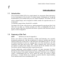
1
Model 2655-00 Flame Photometer
Operator
Manual
Copyright 2001 Cole Parmer Instrument Company.
All rights reserved.
Model 2655-00 Flame Photometer
Intended Use
The Model 2655-00 is a single channel, low temperature flame photometer for the
determination of Na, K and Li.
This operatorÕs manual contains complete instructions for setting up and using the Model
2655-00. Service information for use by appropriately qualified personnel is also available.
The Model 2655-00 is intended for use by persons knowledgeable in safe laboratory practices.
If the instrument is not used in accordance with these instructions for use, the protection
provided by the equipment may be impaired.
WARNING The Model 2655-00 is designed to be grounded through the power supply lead (line
cord) for safe operation. For the safety of operating personnel and optimum
performance make sure that the instrument is only connected to a 3-prong socket
(outlet) that has an effective earth connection. If you are in any doubt about the
safety of your electrical supply system consult a competent, qualified electrician.
There are no user replaceable parts within the instrument. Do not remove the rear cover from
the instrument.
Cole Parmer Instrument Company and its authorized Distributors and Agents consider
themselves responsible for the effects of safety, reliability and performance of the Model 265500 only if:
¥
Assembly operations, extensions, re-adjustments, modifications or repairs
are only carried out by persons authorized by them.
¥
The electrical installation of the relevant room complies with IEC
requirements or the local regulatory code.
¥
The equipment is used in accordance with the instructions for use.
The information contained in this manual was correct at the time of going to print. However,
Cole ParmerÕs policy is one of continuous product improvement and the right to change
specifications, equipment and maintenance procedures at any time, without notice, are
reserved.
This manual is copyrighted, and all rights are reserved. No part of this manual may be
reproduced by any means or in any form without prior consent in writing.
Cole Parmer Instrument Company,
635 East Bunker Court,
Vernon Hills,
IL, 60061,
USA
Tel : 847-549-7600
Tol free : 800-323-4340
Fax : 847-247-2929
Model 2655-00 Flame Photometer
Contents
Page
Intended Use.............................................................................................................................. 2
Introduction............................................................................................................................... 5
1.1
Introduction....................................................................................................... 5
1.2
Summary of the Test.......................................................................................... 5
1.3
Reagents............................................................................................................. 6
Purification........................................................................................................ 6
Installation ................................................................................................................................ 7
2.1
Services Required................................................................................................ 7
Electrical Supply................................................................................................ 7
Fuel.................................................................................................................... 7
Air..................................................................................................................... 7
Waste Container................................................................................................ 7
2.2
Site Conditions................................................................................................... 8
2.3
Unpacking.......................................................................................................... 9
Accessory List ................................................................................................... 9
2.4
Assembly............................................................................................................ 9
2.5
Connecting a Chart Recorder............................................................................ 15
Principles of Operation............................................................................................................ 16
3.1
Flame Photometry........................................................................................... 16
Performance Characteristics and Specification ......................................................................... 17
4.1
Readout............................................................................................................ 17
4.2
Measurement Ranges........................................................................................ 17
4.3
Specificity........................................................................................................ 17
4.4
Accuracy.......................................................................................................... 17
Linearity.......................................................................................................... 17
Drift ................................................................................................................ 17
Reproducibility................................................................................................. 18
4.5
Warm Up......................................................................................................... 18
4.6
Sample Requirement......................................................................................... 18
Type................................................................................................................ 18
Method of presentation ................................................................................... 18
Volume ............................................................................................................ 18
4.7
Chart Recorder Output ..................................................................................... 18
4.8
Environmental Conditions ............................................................................... 19
Temperature.................................................................................................... 19
Humidity.......................................................................................................... 19
Installation Category ....................................................................................... 19
4.9
Power Requirements......................................................................................... 19
Voltage ............................................................................................................ 19
Fuses................................................................................................................ 19
Power .............................................................................................................. 19
4.10 Fuel.................................................................................................................. 19
4.11 Air ................................................................................................................... 19
4.12 Size .................................................................................................................. 19
4.13 Weight............................................................................................................. 19
Model 2655-00 Flame Photometer
Contents
Page
Operating Instructions ............................................................................................................. 20
5.1
Front Panel Controls and Indicators (See Fig 5.1)............................................. 20
Power on ......................................................................................................... 20
Flame on.......................................................................................................... 20
Blank............................................................................................................... 20
Sensitivity Fine and Coarse .............................................................................. 20
Fuel.................................................................................................................. 20
Na, K, Li.......................................................................................................... 20
Decimal ........................................................................................................... 20
Power 0/1 ........................................................................................................ 20
5.2
Rear Panel Controls and ConnectorsÉÉÉÉÉÉÉÉÉÉÉÉÉÉÉÉÉÉ..22
Power .............................................................................................................. 23
Data output...................................................................................................... 23
Gas................................................................................................................... 23
Air................................................................................................................... 23
Air regulator .................................................................................................... 23
5.3
Initial Adjustment ............................................................................................ 24
5.4
Operating Instructions...................................................................................... 25
5.5
Shutdown Procedure ......................................................................................... 27
5.6
Operating Hints................................................................................................ 27
Operational Precautions and Limitations ................................................................................. 28
6.1
General............................................................................................................. 28
6.2
Hazards ............................................................................................................ 28
Maintenance............................................................................................................................ 29
7.1
General............................................................................................................. 29
7.2
Daily Maintenance........................................................................................... 29
7.3
Weekly Maintenance ....................................................................................... 29
7.4
Monthly Maintenance...................................................................................... 29
7.5
Six-Monthly Maintenance................................................................................ 30
7.6
Nebuliser .......................................................................................................... 30
Operational Check........................................................................................... 30
Cleaning the Nebuliser...................................................................................... 30
7.7
Cleaning the Mixing Chamber, Burner and Drain.............................................. 32
7.8
Cleaning the Optical Filters and Glass Chimney ................................................ 33
7.9
Voltage Selection and Fuse Replacement........................................................... 35
7.10 Deproteinising or Disinfecting Procedure ......................................................... 36
Troubleshooting....................................................................................................................... 37
8.1
Power on LED not illuminated......................................................................... 37
8.2
Flame on LED not illuminated ......................................................................... 37
General ............................................................................................................ 37
Air Supply........................................................................................................ 37
Fuel Supply ...................................................................................................... 37
8.3
Unable to set display to zero ............................................................................ 38
8.4
Unable to set display to standard reading .......................................................... 38
8.5
Unstable results ................................................................................................ 38
8.6
Non-linear results............................................................................................. 39
Spares and Accessories ............................................................................................................. 40
9.1
Ordering Information....................................................................................... 40
9.2
Spares and Accessories...................................................................................... 40
9.3
Standard Solutions ............................................................................................ 41
Appendix A ............................................................................................................................. 42
Bibliograph
42
Model 2655-00 Flame Photometer
1
Introduction
1.1
Introduction
The Cole Parmer Model 2655-00 is a single channel, low temperature flame photometer
for the determination of Na, K and Li in clinical samples. Information on Ca and Ba
determinations is also available from your Cole Parmer distributor. The Model 2655-00
utilises a digital display and is designed for reliable, trouble-free operation and ease of
maintenance.
An automatic sample dilutor, Model 805 is available.
The Model 2655-00 has a fail-safe device, which automatically stops the gas flow if the
flame does not ignite, or if during operation, the flame is extinguished. Plus an air
pressure switch so that if the air pressure falls below a specified value the flame will not
ignite or will be extinguished.
1.2
Summary of the Test
NOTE
References are listed in Appendix A.
Prior to the advent of flame photometry, Sodium and Potassium were typically
determined gravimetrically after the precipitation of relatively insoluble salts such as
Sodium Uranyl Zinc Acetate (Ref. 1) and Potassium Chloroplatinate (Ref. 2). As with
all chemical methods for these two elements there were cross interferences and also
interference from other ions such as NH4+. Many analytical steps such as protein
precipitation or ashing of the sample were involved with all the attendant losses and
inaccuracies and the complete procedures required many hours.
In many applications, rapid availability of results is of prime importance. By flame
photometry both sodium and potassium results on a single sample can be available in
less than 5 minutes of the sample reaching the laboratory. (The same is true of lithium
results, a determination that was never carried out before the advent of flame
photometry). A simple dilution step is all that is required; therefore sample handling,
losses and inaccuracies are at a minimum (Ref. 3-10)
Model 2655-00 Flame Photometer
Introduction
1.3
continued
Reagents
Cole Parmer supply a wide range of reagents, including standards, diluent and
maintenance solutions, for use with the Model 2655-00 Flame Photometer.
Please refer to Section 9.3 for a complete list of the reagents available.
Dilutions
Samples and standards must be diluted with the same batch of diluent, made up of 1
part Diluent Concentrate to 999 parts deionised or good quality distilled water.
The same batch of diluent should be used to zero the instrument and to prepare
dilutions of standards and samples. This will prevent variations in water purity
affecting the measurements.
Great care should be taken so that contamination does not occur when preparing the
samples and standards. Remember that the accuracy of the instrument is dependent on
the accuracy and purity of the standards used for calibration.
Storage
All solutions should be stored away from direct sunlight, in a cool place (below
+25¡C/+77¡F), in an airtight container to prevent evaporation and discolouration. Glass
containers should not be used, as they can affect Na concentration levels. Prolonged
exposure to the atmosphere must be avoided to prevent evaporation of standard
solutions, which could affect concentration.
Purification
No purification is required for Cole Parmer standard solutions.
Model 2655-00 Flame Photometer
2
Installation
2.1
Services Required
Electrical Supply
An a.c. supply at 100V, 120V, 220V or 240V ±10%, at 50 or 60Hz, is required for the
Model 2655-00. The instrument operating voltage is shown on the voltage selector on
the rear panel.
CAUTION If the voltage setting is not correct for the local supply, do not attempt to use
the instrument until it is correctly adjusted as detailed in Section 2.4,
paragraph 23.
Fuel
A supply of Propane, Butane or Propane/Butane mixture regulated at the cylinder to
2.1kg/cm_ (30psig), flow rate at least 0.4 litres per minute. The use of industrial quality
gas is not recommended as impurities can enter the delicate gas regulators and can leave
deposits of oil and dirt, which will render the instrument inoperable.
Natural gas at 3 to 10 inches water gauge, regulated to 2 inches water gauge, can also be
used. Natural gas and camping gas regulators are available as optional accessories, refer
to Section 9.2.
NB The positioning of Gas cylinders should conform to National and local regulations.
Air
A supply of clean, dry, oil-free air at 1kg/cm_ (14psig), flow rate 6 litres per minute. A
suitable air compressor is listed in Section 9.2.
Waste Container
A sink or waste container sited to the right of the instrument will ensure the minimum
length of waste tubing. Do not use a waste container with high sides, as this will cause
the drain tube to be lifted above the level of the constant head drain.
Model 2655-00 Flame Photometer
Installation
2.2
continued
Site Conditions
WARNING Under no circumstances install the instrument beneath overhanging
cupboards. There must be at least 1 metre of clear space above the
chimney.
For optimum performance, this instrument should be installed in
accordance with the following conditions: 1.
The environment must be clean and free from dust.
2.
The instrument must be placed on a strong, level worktop, free from vibration. The
Model 2655-00 requires approximately 500mm x 500mm of bench space, which
includes an area in front for solutions and clearance at the rear for fuel and air
tubing, with clear access to the mains supply switch.
3.
Avoid sites that expose the instrument to direct sunlight or draughts.
4.
To meet the specification the ambient temperature must be within the range +10¡C
to +35¡C and the maximum relative humidity must not be more than 85%, noncondensing.
5.
Make sure that the correct voltage is selected for the local a.c. supply, as shown in
the following table. Do not attempt to connect the power supply lead until the
voltage is correctly set.
VOLTAGE SELECTED
100V
120V
220V
240V
VOLTAGE RANGE
90V to 110V
100V to 132V
198V to 229V
230V to 264V
Model 2655-00 Flame Photometer
Installation
2.3
continued
Unpacking
1.
Unpack the instrument and accessories.
NOTE The Model 2655-00 weighs 9.5kg, follow safe lifting techniques.
2.
Check all items for damage.
3.
Check that all the items on the Accessory List have been delivered. Contact your
Cole Parmer distributor if you have any problems.
4.
The Model 2655-00 is shipped with the following items:
Accessory List
2.4
CAT. NO.
ITEM
001 72 043
metres
001 72 114
400 22 002
100 594
471 71 900
100 99 010
pack
001 31 076
400 27 001
400 22 003
410 91 001
001 08 718
001 56 120
500 ml
001 56 121
500 ml
001 56 122
500 ml
Air tubing, nylon reinforced
QUANTITY
2
Fuel tubing
2 metres
Drain tube, 200 mm, and spare tube 200mm 1 pack
Fuse, 200 mA slo-blo, spares
2
Supply lead, a.c.
1
Nebuliser cleaning wire, pack of 3
1
ÔOÕ ring, spare for mixing chamber
Nebuliser
Nebuliser inlet tube, polythene, 150mm
Operators Manual, English
ÔUnexÕ tubing clamp
Flame Photometer Standard, 1000ppm Na,
1
1
4
1 bottle,
Flame Photometer Standard, 1000ppm K,
1 bottle,
Flame Photometer Standard, 1000ppm Li,
1 bottle,
1
1
Assembly
EQUIPMENT REQUIRED: ÔPozidrivÕ (cross head) screwdriver 1PT;
Flat blade screwdriver.
To assemble the Model 2655-00, proceed as follows:
1.
Lift off the chimney cap from the chimney assembly and lift out the glass
chimney. Remove any packing material from inside, making sure that there are
no small pieces left within the chimney.
2.
Replace the glass chimney with the clear strip at the bottom and refit the chimney
cap on top of the chimney.
3.
Remove the nebuliser from its box and screw it to the connector on the end of
the air tubing (item 3, Figure 2.1). Fit the nebuliser to the mixing chamber and
position the retainer to lock it into position (item 2, Figure 2.1). Fit the nebuliser
inlet tube making sure that it is pointing downwards
Model 2655-00 Flame Photometer
Installation
2.4
continued
Assembly
continued
Figure 2.1
Mixing Chamber
1. Nebuliser. 2. Nebuliser retainer. 3. Air tubing. 4. Constant head drain.
5. Fuel restrictor. 6. Fuel tubing.
4.
If the instrument is to be used on Natural gas, proceed with paragraph 11. If
Propane or Butane is to be used continue with paragraph 5.
5.
Connect the length of rubberised fuel tubing, (001 72 114) supplied, between the
inlet connector on the Propane regulator, (item 5, Figure 2.2) and the cylinder
regulator outlet connector. Secure with ÕUnexÕ tubing clamps, supplied. Ensure
that the connector at the regulator inlet is tightened to 12nm torque. Continue
with paragraph 15.
NB
The connection at the cylinder end of the tube must comply with
National regulations.
6.
Remove the fuel restrictor (item 5, Figure 2.1) and connect the fuel tubing (item
6, Figure 2.1) directly to the mixing chamber connection.
7.
Unscrew and remove the gas inlet, regulator inlet and regulator outlet connectors
(items 4, 5 and 6, Figure 2.2) and remove the copper tubing (item 2, Figure 2.2).
8.
Connect the regulator inlet, with connector, (item 5, Figure 2.2) to the gas inlet
(item 4, Figure 2.2).
Model 2655-00 Flame Photometer
Installation
2.4
continued
Assembly
continued
Figure
2.2 Rear Panel
1. Natural gas regulator assembly (see Figure 2.3). 2. Copper tubing.
3. Air regulator adjuster. 4. Gas inlet connector. 5. Regulator inlet connector.
6. Regulator outlet connector.
9.
Locate the Natural gas regulator and mounting bracket ordered as optional
accessories and packed separately from the instrument. Fit the mounting bracket
to the rear panel with the two screws supplied and slot in the Natural gas
regulator, Figure 2.3. Make sure that the gas flow arrow on the regulator points
to the right.
10.
Connect the Natural gas supply to the Natural gas regulator inlet with the fuel
tubing and ÔUnexÕ clamp supplied with the instrument.
Model 2655-00 Flame Photometer
Installation
2.4
continued
Assembly
continued
11.
If it is necessary to fit the filter because of suspected dirty gas then this should
be fitted before the Natural Gas regulator by cutting the rubber hose and fitting
the filter in the tubing with the arrow pointing towards the regulator. Secure the
tubing to the filter and regulator with the extra Unex clips supplied with the
Natural Gas regulator kit.
12.
Connect the Natural gas outlet tubing (supplied with the regulator) to the gas
inlet connector (item 4, Figure 2.2), using the connector and nipple removed as
described in paragraph 7 above bypassing the Propane/Butane regulator. Secure
with ÔUnexÕ clamp supplied.
Figure 2.3
Natural Gas Regulator
1. Regulator screw cap. 2. Filter in line with Rubber hose supplied with the
instrument. 3. Natural gas outlet tubing. 4. Mounting bracket.
13.
Remove the screw cap (item 1, Figure.2.3). Rotate the screw head fully
clockwise, and then counterclockwise exactly one turn.
14.
Refit screw cap.
15.
Turn on the fuel supply and check all connectors for leaks, using soap solution.
Do not use the instrument until you are satisfied that the installation is
leakproof.
16.
Connect the length of reinforced Nylon hose, supplied, between the air
compressor outlet and the air inlet connector on the rear panel. Secure both ends
with ÔUnexÕ tubing clamps, supplied.
Model 2655-00 Flame Photometer
Installation
2.4
continued
Assembly
17.
continued
Fit one of the 200mm lengths of drain tubing (item 4, Figure 2.4) to the outlet on
the constant head drain (or Gas Trap). If necessary connect a suitable length of
tubing (not supplied), to extend the drain tubing to carry waste to a sink or other
drain receptacle. The downward flow of waste must not be restricted. The
second length of tubing supplied is a spare for either the ÔUÕ tube or drain tube.
Figure 2.4
Filling the ÔUÕ Tube
1. Wash bottle. 2. Constant head drain (Gas Trap). 3. ÔUÕ tube. 4. Drain tube.
5. Spring clip.
18.
Make sure that the constant head drain (Gas Trap) is positioned so that the lip
at the top is resting on the spring clip. Use a wash bottle (item 1, Figure 2.4) to
fill the ÔUÕ tube with deionised water. Sufficient water should be used to purge
the tube of air. Allow excess water to flow back into the drain.
IMPORTANT Do not continue until you are satisfied that the ÔUÕ tube has been
completely filled with water, and is purged of air.
Model 2655-00 Flame Photometer
Installation
2.4
continued
Assembly
19.
continued
The instrument is supplied with Na, K and Li filters fitted. To replace any of
these filters, refer to Section 7.8.
Figure 2.5
Voltage Selector
1. Voltage selector. 2. Fuse holders.
20.
Check that the voltage shown on the voltage selector is correct for the local
supply. If it is not, open the voltage selector compartment. Slide the voltage
selector bobbin, item 1, Figure 2.5 out of the instrument and replace it so that
the required voltage setting will be visible through the window of the
compartment cover. Close the compartment cover.
CAUTION Do not attempt to rotate the voltage selector bobbin when it is fitted
in the voltage selector, as this will damage the contacts.
21.
Fit a suitable 3-pin plug to the a.c. supply lead. Check that the correct colour
coded leads are connected to the plug terminals. Follow the plug manufacturerÕs
fitting instructions.
CAUTION Ensure that the green/yellow earth connector in the a.c. supply lead
is connected to a properly grounded earth point, the brown lead is
connected to the Line terminal (L) and blue lead is connected to the
Neutral terminal (N).
22.
If necessary, set the power switch (below the chimney) to the 0 position.
Connect the a.c. supply lead to the power receptacle on the rear panel and
connect the plug to a convenient supply socket.
23.
If a chart recorder is to be used with the instrument continue with Section 2.5. If
not, continue with Section 5, Operating Instructions.
Model 2655-00 Flame Photometer
Installation
2.5
continued
Connecting a Chart Recorder
1.
Connect a black plug (Cat. No. 001 42 017) to the black (-ve) recorder input lead
and a red plug (Cat. No. 001 42 254) to the red (+ve) input lead.
2.
Fit the plugs into the appropriate data output sockets on the rear panel of the
instrument.
3.
If the chart recorder has an input-shorting link fitted, connect it between the
black (negative) input and the earth input. This may reduce interference and
produce a better trace.
7.
Continue with Section 5, Operating Instructions.
Model 2655-00 Flame Photometer
3
Principles of Operation
3.1
Flame Photometry
When metal ions in solution are aspirated into a low temperature flame (in an aerosol
form) the electrons of the ion are excited to higher energy states.
When these electrons return to the ground state, they lose the excitation energy and a
discrete wavelength of visible light is emitted. This light wavelength can be isolated from
other light wavelengths by an optical filter and the amount of light emitted can be
detected with a suitable photodetector. The amount of light emitted is proportional (for
low concentrations of metal ion only) to the number of ions in the flame and hence the
number of ions in solution.
The electrical signal from the photodetector is amplified and displayed on a digital
readout.
Model 2655-00 Flame Photometer
4
Performance Characteristics and Specification
4.1
Readout
3_-digit light emitting diode (LED) display, 12.5mm high.
Display range 0 to 1999 (199.9 with decimal point on).
NOTE If negative values are displayed the instrument is operating outside of the
recommended measurement range.
4.2
Measurement Ranges
Na
0-10ppm linear;
Above this range Na is non-linear due to self-absorption. A lineariser can
be fitted, which will linearise concentrations up to 60ppm Na. (Part
number 47829800).
K, Li & Ca
0 to 100ppm.
Ba
0-3000ppm
These are sample concentrations directly entering the flame photometer after dilution.
4.3
Specificity
For Na, K and Li measurements, interference will be less than 0.5% from a
concentration of Na, K, Li, Ca or Ba, equal to the concentration of the element under
test.
4.4
Accuracy
Linearity
Better than 2% measured at mid-range, when standardized at the following
concentrations 3ppm Na, 3ppm K & 5ppm Li.
Drift
At zero:
Better than 2% per hour when calibrated at 10ppm for Na, K and Li.
At 10ppm:
NOTE
Better than 2% per 5 minutes, for Na, K and Li, based on 10 consecutive
samples, aspirating sample for 20 seconds, then 10 seconds of air.
A minimum 30 minutes warm up must be allowed to meet the drift
specification, refer to Section 4.5.
Performance Characteristics and Specification
4.4 Accuracy continued
Model 2655-00 Flame Photometer
continued
Reproducibility
NOTE The following specification is correct for use on Propane or Butane. If Natural
Gas is used the reproducibility may be slightly worse.
Less than 2% CV for 20 consecutive readings of the same bulk sample, aspirating
sample for 20 seconds then 10 seconds of air. The concentration of the bulk sample to
be 10ppm for Na, K and Li which will give a standardized reading of 100 on the
display, i.e. 10.0 with decimal point on.
4.5
Warm Up
To achieve the stated specification the flame must be alight for a minimum of 30
minutes, with diluent being aspirated.
4.6
Sample Requirement
Type
Dependent on application. However, samples should be water-based and not highly
viscous nor non-homogeneous.
Organic solvents affect the air/fuel ratio, could attack the mixing chamber materials and
can affect the safety operation of the Gas Trap (constant head drain) and should be
used with great caution.
Method of presentation
The sample is presented to the nebuliser from a sample cup, test-tube, or other suitable
container.
Volume
The maximum diluted sample volume required for 20 seconds aspiration is 2ml.
4.7
Chart Recorder Output
Nominal 100mV signal output per 1000 display units.
Performance Characteristics and
4.8
Model 2655-00 Flame Photometer
Specification continued
Environmental Conditions
Temperature
Operating +10¡C to +35¡C; Transportation -40¡C to +45¡C.
Humidity
Operating
85% maximum at +35¡C.
Transportation
95% maximum at +45¡C (non condensing).
The instrument specification will be unaffected by an ambient temperature change of
4¡C (or less) per hour, within the range +10¡C to +35¡C, with a maximum of 7¡C shift
during 8 hours.
Installation Category
Installation Category 1.
4.9
Power Requirements
Voltage
90V to 132V or 198V to 264V, 50/60Hz.
Fuses
Two 200mA slo-blo fuses are fitted for all voltage ranges.
Power
20VA.
4.10 Fuel
High-grade Propane, Butane or Propane/Butane mixture. All fuels to be free of heavy
hydrocarbon deposits and regulated at the cylinder to approximately 2.1kg/cm_
(30psig). Natural Gas at 3 to 10 inches water gauge, regulated to 2 inches water gauge,
using optional natural gas regulator.
NOTE Natural Gas may give reproducibility results outside specification.
4.11 Air
A supply of clean air at a minimum pressure of 1kg/cm_ (14psig) at 6 litres/minute, as
supplied by a Model 851 Air Compressor. Maximum inlet pressure 2.1kg/cm_
(30psig). If condensation problems arise a Model 856 Air Compressor should be used,
which has a water separator fitted.
4.12 Size
Overall, including chimney and rear panel connectors, 510mm high x 390mm wide x
345mm deep.
4 13 Weight
Model 2655-00 Flame Photometer
5
Operating Instructions
5.1
Front Panel Controls and Indicators (See Fig 5.1).
Power on
LED which illuminates when the instrument is switched on.
Flame on
LED which illuminates when the flame is alight.
Blank
This control is used to set the display to zero while aspirating a blank solution.
Sensitivity Fine and Coarse
These two controls are used to set the display to an appropriate concentration reading,
while aspirating a standard solution. The coarse control is a four position rotary switch
and the fine control is a 10-turn potentiometer.
Fuel
This control provides a fine adjustment of the fuel flow and enables the optimum flame
conditions to be set for each element.
Na, K, Li
This three-position slider control selects the correct filter for the element to be determined.
When used with other filter types e.g. Ca or Ba, the appropriate label should be fitted in
the relevant position, on the front of the chimney assembly.
Decimal
This touch control, located adjacent to the digital display, is used to select the decimal
point, e.g. using the decimal pushbutton to select the decimal point, a reading of 1000 will
be displayed as 100.0. The sensitivity of the Model 2655-00 is unaffected by use of this
control.
Power 0/1
Rocker switch that switches the a.c. power supply on (1) and off (0). When the instrument
is switched on, the power on LED is illuminated, and an ignition cycle is initiated. When
switched off, the flame is extinguished and the a.c. supply to the instrument is switched
off.
Model 2655-00 Flame Photometer
Operating Instructions continued
5.1
Front Panel Controls and Indicators continued
Figure 5.1
Front Panel
1. Filter selector. 2. Digital display. 3. Inspection flap. 4. Fuel adjustment control. 5. Blank
control.
6. Coarse sensitivity control. 7. Fine sensitivity control. 8. Decimal pushbutton. 9. Power
switch.
10. Power on LED. 11. Flame on LED.
Model 2655-00 Flame Photometer
Operating Instructions continued
5.2
Rear Panel Controls and Connectors
Figure 5.2
Rear Panel
1. Power connector and voltage selector. 2. Gas inlet connector. 3. Data output
sockets.
4. Air inlet connector. 5. Air pressure gauge and air regulator adjuster.
6. Propane/Butane regulator inlet connector.
Model 2655-00 Flame Photometer
Operating Instructions continued
5.2
Rear Panel Controls and Connectors continued
IEC symbol advising user to refer to accompanying documentation.
Serial Plate ~symbol denotes equipment suitable for alternating current
only.
Power
Three pin connector for the a.c. supply lead incorporating a voltage selector and fuse
compartment.
Data output
Two colour coded chart recorder sockets. The nominal +100mV /1000 display digits
output signal is on the red socket with respect to the black socket.
Gas
1/4-inch fuel inlet connector to the instrument, permanently connected to the cylinder
regulator outlet. The instrument will operate satisfactorily on Propane and Butane, or
Natural Gas, using the natural gas regulator available as an optional accessory, refer to
Section 9.2. See Section 4.10 for pressure and flow rate specifications.
Air
5/16-inch connector for the air inlet tubing to the instrument, from the air compressor
outlet. See Section 4.11 for pressure and flow rate specifications.
Air regulator
Control to adjust the pressure of the air supply. The air pressure gauge provides a
visual indication of the air pressure.
Model 2655-00 Flame Photometer
Operating Instructions continued
5.3
Initial Adjustment
NOTE The following instructions assume that the air compressor is switched on and
supplying the instrument with air.
1.
Check that the air pressure gauge (on the rear panel) indicates a reading between
11 and 13psig. If it does not, lower the air regulator locking ring and adjust the
regulator for a reading of 1 psig on the air pressure gauge. Raise the locking ring
to lock the air regulator adjuster.
WARNING The air compressor should always be switched on before the flame
is ignited. The gas will not flow without sufficient air pressure
2.
3.
Check the Gas Trap ÔUÕ tube is filled with water; refer to Section 2.4, paragraph
18.
Turn the fuel control fully clockwise to the closed position, but do not force it.
This control is a precision assembly that will be damaged by rough handling.
WARNING Always check that the gas installation is leak-proof before initiating
an ignition cycle.
4.
-
Open the fuel control the required number of turns counterclockwise as follows:
Fuel
Propane
Butane
Natural Gas
No. of Turns
9
11
16
5.
Turn on the fuel supply at source.
6.
Depress the power switch on the front panel. The power on LED will
illuminate, and an ignition cycle will commence.
7.
If the flame on LED has not illuminated before the end of the ignition cycle,
switch off and wait ten seconds. Then, without adjusting the fuel control, in
case the instrument fuel system is not yet completely filled, switch on again to
initiate another ignition cycle.
8.
Repeat this cycle twice to allow sufficient time for the fuel to reach the burner
then continue to paragraph 9.
9.
If the flame on LED has not illuminated before the end of the ignition cycle,
switch off the power switch. If using Natural Gas continue with paragraph 10.
If using Propane/Butane continue with paragraph 11.
10.
Remove the natural gas regulator screw cap (item 1, Figure 2.3). Rotate the
screw head fully clockwise, and then counterclockwise exactly one and a half
turns. Refit the screw cap.
WARNING Do not exceed this setting as this will lead to a very rich fuel
mixture which may cause a flame to appear above the chimney.
11.
Open the fuel control one turn counterclockwise. Switch on again.
12.
If the flame on LED still does not illuminate, repeat paragraph 11. Do not open
the fuel control more than a total of 4 turns from the settings shown in
paragraph 3.
13.
If the flame on LED still does not illuminate, switch off and refer to Section 8.2,
Troubleshooting.
14
Wh
th
fl
LED ill
i t
d
ith S ti
54 O
ti
Model 2655-00 Flame Photometer
Operating Instructions continued
5.4
Operating Instructions
NOTE For greatest accuracy and stability Cole Parmer recommend that a batch of
diluent is made up from 1 part Diluent Concentrate and 999 parts deionised or
good quality distilled water. Using diluent for setting blank and for dilution of
samples and standards means that all solutions presented to the instrument
contain the stability promoting ingredients contained in the diluent. Always
use the same batch of diluent for the blank and the dilution of samples and
standards. Store the diluent in a sealed container for not more than five days.
WARNING Always check that the gas installation is leakproof before initiating an
ignition cycle.
1.
Turn on the fuel supply at source. Switch on the Air Compressor.
2.
Depress the power switch to switch on the instrument. The power on LED will
be illuminated, and an ignition cycle will commence.
3.
If the flame on LED is not illuminated at the end of the ignition cycle, refer to
Section 5.3 and check the setting of the fuel control.
4.
Set the filter selector to the required position.
5.
Insert the nebuliser inlet tube in a beaker containing 100ml of diluent and allow
30 minutes for the operating temperature to stabilize. This will ensure a stable
burner temperature when solutions are aspirated, after the warm up period.
6.
During the warm up period prepare a set of calibration solutions to cover the
required measurement range. To obtain maximum linearity Cole Parmer
recommend that the highest standard concentration does not exceed 10ppm for
Na, K and Li.
7.
While aspirating diluent, adjust the blank control so that the display reads 0.0.
8.
Aspirate the highest concentration standard.
9.
Allow 20 seconds for a stable reading and then adjust coarse and fine controls
for a convenient reading, e.g.20ppm Na can be set to read 20.0 on the display.
10.
Carefully adjust the fuel control for a maximum reading on the display, ensuring
that only small adjustments are made, with a pause of several seconds between
adjustments.
NOTE If you have any difficulty obtaining a maximum sodium reading proceed
as follows: Open the inspection flap and adjust the fuel control until the
flame just starts to lift off the burner. Then turn the fuel control back,
counterclockwise, until the cones of the flame are on the burner. Close
the flap and proceed with paragraph 11.
11.
Remove the standard solution, wait 10 seconds, then aspirate a blank solution of
diluent for 20 seconds. Adjust the blank control for a 0.0 reading. Remove the
blank solution and wait 10 seconds.
12.
Repeat paragraphs 8, 9 and 11 until the blank reading is 0.0 (within ±0.2) and
the calibration reading is within ±1%. If a chart recorder is being used set zero on
the blank solution and set span while aspirating the calibration standard.
13.
Without touching the fine and coarse controls aspirate each of the remaining
calibration standards for 20 seconds (starting with the lowest concentration to
avoid carry over) again allowing 10 seconds between measurements. Note the
value of each standard and plot the results on a graph against standard
concentration on linear graph paper Refer to example shown in Figure 5 3
Model 2655-00 Flame Photometer
Operating Instructions continued
5.4
Operating Instructions
Figure 5.3
continued
Typical Calibration Curve
14.
Check calibration standards and blank readings.
15.
Dilute the unknown solutions with diluent to give a concentration of the element
under test within the range of the calibration standards. Several attempts might
be necessary to determine the correct dilution ratio.
16.
Aspirate each of the diluted unknowns for 20 seconds, then note the reading.
The concentration of the element in the unknown sample can be calculated by
reading the sample concentration from the calibration curve and multiplying it by
the dilution factor.
17.
Recalibrate the instrument by carrying out paragraphs 8 to 12. Experience in use
will determine how frequently the calibration needs to be checked.
Model 2655-00 Flame Photometer
Operating Instructions continued
5.5
Shutdown Procedure
1.
Aspirate Cleaning Solution diluted 1 in 100 with deionised water, for one
minute.
5.6
2.
Aspirate diluent for two minutes.
3.
For a short-term shutdown (two hours) switch off the instrument power switch
and switch off the compressor.
4.
For a longer term shutdown (overnight) turn off the fuel supply at source. When
the flame on LED is extinguished, switch off the power switch, and the
compressor. This ensures that the fuel pressure in the fuel tubing is at a
minimum.
Operating Hints
1.
The deionised or high quality distilled water used when making a batch of diluent
must be free from contaminating elements. It is recommended that the same
batch of diluent is used to prepare all solutions and to set blank on the
instrument.
2.
Greatest accuracy will be obtained by using the same dilution equipment for
both standard and sample preparation.
3.
Always use suitable standards for calibrating the instrument. Remember that the
accuracy of the results obtained from the Model 2655-00 depend on the
accuracy and purity of the calibration standard that is used.
4.
Applications and Method Sheets are available from your Cole Parmer
distributor.
5.
A guide to Flame Photometry is available from your Cole Parmer distributor.
Model 2655-00 Flame Photometer
6
Operational Precautions and Limitations
6.1
6.2
General
1.
Always dilute samples and standards with the same batch of diluent (made up of
1 part Diluent Concentrate and 999 parts of deionised or good quality distilled
water) which contains non-ionic wetting agents.
2.
The samples should not be highly viscous or non-homogeneous. If possible,
samples likely to contain sediment should be filtered and then mixed to obtain a
representative result.
3.
Always use soap solution when checking for leaks in fuel or air lines. Do not
allow fuel to flow in the presence of unguarded flames, e.g. cigarettes.
4.
Always use genuine Cole Parmer replacement parts. Do not, for example,
replace the ÔUÕ tube with one of different material, bore or length as this will
cause a deterioration in the instrumentÕs performance.
5.
Always carry out the maintenance schedules as detailed in Section 7.
6.
Do not leave the inspection flap open, unless adjusting flame conditions, as this
will allow stray light to enter the chimney.
7.
The front panel of the Model 2655-00 is impervious to a wide range of
chemicals. However, strong acids and some organic solvents e.g. chloroform and
phenol, may affect the finish. Any spillage should be thoroughly wiped away as
soon as possible. If necessary, clean the instrument with warm, soapy water do not use abrasives.
Hazards
1.
All electrical instruments are potentially hazardous. With the exception of the
glass chimney, there are no user maintainable parts inside the Model 2655-00
covers. Never remove covers from the instrument, unless specific maintenance
instructions are being followed.
2.
Propane, Butane and natural gas are highly inflammable and potentially
explosive gases. Propane and Butane are stored as a liquid, under pressure in a
cylinder, for use with the Model 2655-00. Such a cylinder should never be
subjected to heat or mechanical shock. When handled correctly and connected to
the instrument as instructed, the fuel gas is quite safe. Check hosing joints with a
soap solution before allowing any naked flame in the vicinity. Never open a
cylinder valve to atmosphere even on a supposedly empty cylinder.
3.
The chimney cap and glass chimney and the area above the chimney can become
very hot and are capable of causing severe burns. Never view the flame from the
top of the chimney, always use the inspection hole.
4.
Make sure that the air compressor is connected to the power supply and
switched on before starting a flame ignition sequence. Failure to observe this
precaution may result in a build up of fuel gas, which will cause a flame to
appear above the chimney.
Model 2655-00 Flame Photometer
7
Maintenance
7.1
General
Under the Daily, Weekly, Monthly and Six-Monthly Maintenance headings are
summaries of the work and equipment required. The tasks are detailed from Section 7.6
onwards.
For maintenance of the air compressor, dilutor and chart recorder, if used, refer to the
instructions supplied with the equipment.
7.2
Daily Maintenance
EQUIPMENT REQUIRED
None.
1.
Empty waste container, if used.
2.
Check air line for condensation, and drain if necessary.
3.
Check ÔUÕ tube is filled with deionised water.
7.3
Weekly Maintenance
EQUIPMENT REQUIRED
10 ml beaker; Stop watch; Nebuliser cleaning wire; Deproteinising Solution;
Stainless steel nebuliser tube and sleeve, or polythene inlet tube, as required.
7.4
1.
Carry out Daily Maintenance procedure.
2.
Deproteinising the system (Section 7.10).
3.
Check the operation of the nebuliser (Section 7.6).
Monthly Maintenance
EQUIPMENT REQUIRED
As for weekly maintenance.
1.
Carry out Daily and Weekly Maintenance procedures.
2.
Check the constant head drain, mixing chamber, ÔUÕ tube and drain tube and
clean if necessary (Section 7.7). Check that the ÔUÕ tube is refilled with deionised
water on reassembly.
Model 2655-00 Flame Photometer
Maintenance
7.5
continued
Six-Monthly Maintenance
EQUIPMENT REQUIRED
As for weekly maintenance, plus the following: ÔUÕ tube and drain tube, Methanol; tissues; Soft lint free cloth; Cotton buds.
7.6
1.
Carry out the Daily and Weekly Maintenance procedures.
2.
Clean the mixing chamber, burner tube, burner and constant head drain (Section
7.7).
3.
Replace stainless steel nebuliser tube and sleeve, (or polythene nebuliser tube if
fitted), ÔUÕ tube and drain tube.
4.
Clean the optical filters and the glass chimney (Section 7.8).
5.
Check the air and fuel tubing and connectors for leaks, using soap solution.
Check for signs of stress cracking especially at the connectors.
Nebuliser
EQUIPMENT REQUIRED
Stop watch; 10 ml beaker; Cleaning wire; Cleaning Solution;
Stainless steel nebuliser tube and sleeve, or polythene inlet tube, as required.
Operational Check
1.
Turn off the fuel supply at source.
2.
Switch on the M2655-00 and the air compressor. Check that the flame on LED
is off.
3.
Fill the beaker with deionised water, and weigh it.
4.
Present the 10ml beaker of deionised water to the nebuliser tube for an
accurately timed minute.
5.
Reweigh the beaker and calculate the aspiration rate. If it is between 2 and 6
ml/minute, no further action is required. If it is too low, continue with paragraph
6. If it is too high contact your Cole Parmer Distributor. Do not attempt to
adjust the nebuliser, as the capillary position is fixed during manufacture, and is
not adjustable.
Cleaning the Nebuliser
6.
Release the nebuliser retainer (item 1, Figure 7.1) and withdraw the nebuliser
(item 2, Figure 7.1).
7.
Insert a cleaning wire into the nebuliser capillary, and pull right through.
Model 2655-00 Flame Photometer
Maintenance
continued
Cleaning the Nebuliser continued
Figure 7.1
Mixing Chamber
1. Nebuliser retainer. 2. Nebuliser. 3. End cap. 4. Fuel tubing. 5. Air tubing.
6. End cap securing screw. 7. ÔUÕ tube.
8.
Fit new nebuliser inlet tubing to the nebuliser. Recheck the aspiration rate,
paragraphs 3, 4, and 5.
9.
If nebuliser operation is still outside the specification, unscrew the air line
connector and remove the nebuliser inlet tubing.
10.
Soak the nebuliser in a 1 in 100 dilution of Cleaning Solution, agitating it
periodically.
11.
Rinse thoroughly in deionised water and shake dry.
12.
Refit the nebuliser inlet tubing and the air line. Recheck aspiration rate.
13.
If the nebuliser operation is still unsatisfactory, fit a new nebuliser. Do not
attempt to adjust the nebuliser, as the capillary position is fixed during
manufacture, and is not adjustable.
Model 2655-00 Flame Photometer
Maintenance
7.7
continued
Cleaning the Mixing Chamber, Burner and Drain
EQUIPMENT REQUIRED
Flat blade screwdriver, blade width 8 mm; Deproteinising Solution; Tissues.
1.
2.
3.
4.
5.
6.
7.
8.
9.
10.
11.
12.
13.
14.
15.
16.
17.
18.
19.
20.
Check that the flame on LED is off, fuel is turned off at source, and the
instrument and compressor are switched off.
Release the nebuliser retainer and withdraw the nebuliser (items 1 and 2, Figure
7.1).
Disconnect the fuel tubing (item 4, Figure 7.1) from the end cap connector (item
3, Figure 7.1) using a twisting movement. Do not pull the tubing, as this will
make it grip the connector more tightly.
WARNING Use a heat resistant glove when handling the burner and burner tube
if the flame has been alight within the preceding 30 minutes. Do
not proceed until all the parts within the chimney are at a safe
handling temperature.
Remove the chimney cover and lift out the glass chimney.
Disconnect the mixing chamber from the chimney assembly by twisting it to the
right, through 40 degrees. Lower the mixing chamber and burner assembly.
Lift the burner tube from the mixing chamber and remove the burner.
Unscrew the end cap securing screw (item 6, Figure 7.1). Grasp the end cap
(item 3, Figure 7.1) and remove it from the mixing chamber, with a slightly
twisting action. Lift the end cap to allow the water in the ÔUÕ tube to flow into
the constant head drain. Disconnect the ÔUÕ tube from the end cap and constant
head drain.
Unclip the constant head drain and disconnect the drain tube.
Soak all the items removed from the instrument in a 1 in 100 dilution of Cleaning
Solution, agitating it periodically.
Rinse the parts thoroughly in deionised water and dry with clean tissues.
Fit the burner tube to the mixing chamber, ensuring that the locating slot in the
burner tube engages with the locating pin in the mixing chamber.
Fit the burner pointed end downwards into the burner tube. Rotate the burner to
ensure that it is fully inserted.
Check the condition of the end cap Ô0Õ ring seal. If necessary, replace the seal.
Replace the end cap, using a twisting movement. Align the hole with the mixing
chamber screw fixing. Fit the screw (item 6, Figure 7.1).
Carefully position the mixing chamber, with the burner tube inside the chimney.
With the burner tube fully inserted, twist the mixing chamber to the left, through
40 degrees, to lock it in position.
Refit the glass inner chimney and the chimney cover
Fit the constant head drain to the spring clip and position it so that the lip on
the drain is resting on the spring clip.
Connect the fuel tubing to the mixing chamber end cap. Connect the ÔUÕ tube
between the mixing chamber end cap and the constant head drain. Fit the drain
tube to the constant head drain.
Fit the nebuliser into the end cap and position the retainer to lock it.
Use a wash bottle to fill the ÔUÕ tube with deionised water. Sufficient water
should be used to completely fill the ÔUÕ tube and purge it of air.
Model 2655-00 Flame Photometer
Maintenance
7.8
continued
Cleaning the Optical Filters and Glass Chimney
EQUIPMENT REQUIRED
Soft lint free cloth; Methanol; Cotton buds; Tissues; Cleaning Solution.
1.
Check that the flame on LED is off, fuel is turned off at source, and the flame
photometer and compressor are switched off.
WARNING Do not proceed until all the parts within the chimney are at a safe
handling temperature.
2.
Lift off the chimney cap from the chimney assembly. Lift out the glass chimney.
3.
Move the filter selector to the top position, and push the lever upwards and to
the right. This will disengage the filter selector from the stop. Lift the filter
selector out of the chimney.
4.
Position the filter selector on the lint free cloth so that the coloured sides of the
filters are uppermost and the thumb grip is at the top, as shown in Figure 7.2.
CAUTION Handle the optical filters only by the edges, never the faces.
5.
Using a soft probe, (cotton bud or similar), that will not scratch the filters, push
out the first filter. Examine the filter edges and note the wavelength on Figure
7.2, alongside the appropriate space. Remove the remaining two filters and mark
the wavelengths on Figure 7.2.
6
Carefully wipe each filter with a cotton bud soaked in methanol.
7.
Turn the filter selector over so that the large holes and filter retainers are
uppermost.
8.
Refer to Figure 7.2 and carefully replace the filters, mirrored sides upward, into
their respective positions.
7.
Refit the filter selector into position inside the chimney and slide it fully in.
Check that all three positions can be selected.
Model 2655-00 Flame Photometer
Maintenance
7.8
continued
Cleaning the Optical Filters and Glass Chimney continued
Figure 7.2
Filter Selector
10.
Soak the glass chimney in a 1 in 100 dilution of Cleaning Solution, agitating it
periodically.
11.
Rinse the glass chimney thoroughly in deionised water and dry with clean
tissues.
12.
Replace the glass chimney with the clear strip at the bottom. Make sure the glass
chimney is seated correctly and refit the chimney cap on top of the chimney.
Model 2655-00 Flame Photometer
Maintenance
7.9
continued
Voltage Selection and Fuse Replacement
EQUIPMENT REQUIRED
Fuses.
WARNING For continued protection against fire hazard use only the same type and
rating of fuse that was fitted originally to the M2655-00 refer to
instrument rear panel.
l.
2.
Check that the flame on LED is off, fuel is turned off at source, and the
instrument and compressor are switched off.
Disconnect the a.c. supply lead from the a.c. supply socket.
3.
Disconnect the a.c. supply lead from the power connector on the rear panel.
4.
Open the voltage selector compartment and withdraw the voltage selector, item
1, Figure 7.3. To replace fuses continue with paragraph 5; to change the
operating voltage continue with paragraph 7.
5.
Slide out the two fuse holders, item 2, Figure 7.3, and remove the fuses.
6.
Replace any burned out fuses and slide in the fuse holders.
7.
Replace the voltage selector so that the required voltage setting is visible through
the window of the compartment cover. Close the compartment cover and refit
the a.c. supply lead.
Figure 7.3
Voltage Selector and Fuse
1. Voltage selector. 2. Fuse holders
Model 2655-00 Flame Photometer
Maintenance
continued
7.10 Deproteinising or Disinfecting Procedure
NOTE To deproteinise the system use Deproteinising Solution, to disinfect the system
use Tubing Disinfectant.
EQUIPMENT REQUIRED
Deproteinising Solution or Tubing Disinfectant.
1.
Light the flame as detailed in Section 5.4.
2.
Present a beaker of Deproteinising Solution or Tubing Disinfectant to the
nebuliser for 10 minutes.
3.
After 10 minutes have elapsed, replace the beaker of solution with a beaker of
deionised water. Flush the system for two minutes.
4.
Shutdown the instrument as detailed in Section 5.5.
Model 2655-00 Flame Photometer
8
Troubleshooting
8.1
Power on LED not illuminated
Check that the instrument is connected to a working a.c. supply, and that the power
switch is depressed.
Check the plug fuse and replace if necessary. Check the instrument fuses and replace if
required, refer to Section 7.9.
If fault persists contact your Cole Parmer Distributor.
8.2
Flame on LED not illuminated
General
Ensure that the ÔUÕ tube is filled with deionised water, refer to Figure 2.4.
Burner must be fitted with pointed end downwards, refer to Section 7.7.
Air Supply
Air compressor must be connected to an a.c. supply, and working correctly.
Check the air tubing connections from the air compressor to the instrument, refer to the
air compressor manual.
Fuel Supply
There must be a compressed air flow otherwise the air pressure switch will not allow
the gas to flow into the instrument.
Check that there is an adequate supply of fuel.
Fuel supply must be turned on at source. If using a long length of fuel tubing, try
repeating the ignition sequence a few times to allow the fuel to fill the tubing.
If using natural gas, check the setting of the natural gas regulator, refer to Section 5.3.
If the fuel is propane or butane check that the regulator at the cylinder is adjusted for
2.1kg/cm_ (30psig).
Check the fuel control is set correctly, refer to Section 5.3.
If the fuel restrictor (propane/butane only) is blocked, clean with the nebuliser cleaning
wire, refer to Figure 2.1. If fault persists contact your Cole Parmer Distributor.
Model 2655-00 Flame Photometer
Troubleshooting
8.3
continued
Unable to set display to zero
Check that diluent is being aspirated.
The deionised water supply may be contaminated, use a better grade of deionised water.
The burner may be encrusted with salt deposits. Clean the burner as detailed in Section
7.7.
If using a chart recorder check that the data output connections are correct.
If fault persists contact your Cole Parmer Distributor.
8.4
Unable to set display to standard reading
Check the concentration of the standard being aspirated, and that the dilution ratio of
this standard is correct.
Use fresh deionised water and recalibrate zero. If using low-grade deionised water the
background levels may be too high.
Make sure the correct filter has been selected. If there is a chance that the optical filters
may have been serviced, check that they have been fitted correctly, refer to Section 7.8.
The nebuliser may be blocked. Check the nebuliser, refer to Section 7.6.
Check the glass chimney is clean, refer to Section 7.8.
Make sure the fuel control is set correctly, refer to Section 5.3.
If the atmosphere surrounding the instrument, or air compressor inlet, is contaminated
(e.g. smoke) incorrect readings may result.
If fault persists contact your Cole Parmer Distributor.
8.5
Unstable results
Do not use compressed air from a ÒcommunalÓ source or ÒAir LineÓ as this may be
contaminated with oil, which will ruin the performance of the Model 2655-00. Use a
dedicated Compressor such as the Model 851 or Model 855.
Check the concentration of the solutions being aspirated. The solutions should all
contain 1 in 1000 dilution of Diluent Concentrate, refer to Section 5.4.
Check the fuel supply is adequate. Make sure the fuel control is set correctly, refer to
Section 5.3.
The use of Natural Gas from a Òcommunal sourceÓ will fluctuate as other users turn on
or turn off their gas taps. Wherever possible, use bottled gas.
The nebuliser may be blocked. Check the nebuliser, refer Section 7.6.
The ÔUÕ tube or drain tubing may be blocked or partially obstructed.
If the air supply tubing show signs of condensation, drain the air tubing. If this problem
recurs frequently use a Model 856 air compressor with water separator.
Make sure the air compressor filter is changed regularly, refer air compressor manual.
If the atmosphere surrounding the flame photometer, or air compressor inlet, is
contaminated (e.g. smoke) unstable readings may result. A similar effect may be
observed if the instrument is sited in a draught. If fault persists contact your Cole
Parmer Distributor.
Model 2655-00 Flame Photometer
Troubleshooting
8.6
continued
Non-linear results
Check the concentration of the solutions being aspirated. The solutions should all
contain 1 in 1000 dilution of Diluent Concentrate, refer Section 5.4. Make up fresh
solutions and recheck calibration curve.
Check that the fuel supply is adequate. Make sure the fuel control is set correctly, refer
Section 5.3.
The nebuliser may be blocked. Check the nebuliser, refer Section 7.6.
The ÔUÕ tube or drain tubing may be blocked or partially obstructed.
Use fresh deionised water and recalibrate zero. If using low-grade deionised water the
background levels may be too high.
If fault persists contact your Cole Parmer Distributor.
Model 2655-00 Flame Photometer
9
Spares and Accessories
9.1
Ordering Information
When ordering spares or accessories for your instrument, please give the following
information to your Cole Parmer distributor.
2655-00 Serial No.
Catalog No. of Part (Cat. No.)
Description
Quantity required
This will ensure that your order is dealt with quickly and efficiently.
The number shown in the third column (Quantity) is the quantity of items that are
supplied against the stated Catalog Number. If the quantity is greater than 1, then only
multiples of that quantity can be supplied.
9.2
Spares and Accessories
CAT. NO.
ITEM
400 27 001
410 26 001
402 12 00l
400 02 013
410 04 010
100594
400 22 003
400 20 001
410 19 002
001 26 033
001 42 017
001 42 254
989 05 137
989 05 138
989 05 139
400 16 004
400 16 005
410 21 001
Nebuliser
1
Mixing chamber and burner
1
End Cap Assembly
1
End cap securing screw
1
Constant Head and Drain
1
Fuse, 200mA, slo-blo
1
Nebuliser inlet tube, polythene, 150mm each 1
Fuel restrictor
1
Natural gas regulator kit with filter
1
Sample pot, plastic, in packs of 50
1 pack
Recorder plug, black
1
Recorder plug, red
1
Sodium filter, 589.6nm
1
Potassium filter, 768nm
1
Lithium filter, 671nm
1
Calcium filter, 620nm, with label
1
Barium filter, 520nm, with label
1
Filter holder
(recommended for use with Ca and Ba filters) 1
Propane primary regulator, cylinder fixing
1
Butane primary regulator (3080)
for 15lb Calor/Caravan cylinder
1
001 08 234
001 08 733
QUANTITY
Model 2655-00 Flame Photometer
Spares and Accessories continued
9.3
CAT. NO.
ITEM
001 08 439
Butane primary regulator (182H)
for 32lb Calor/Caravan cylinder
1
Butane primary regulator for ÔGazÕ type cylinder
1
Fuel tubing
per metre
Air tubing
per metre
ÔUnexÕ tubing clamp
1
Nebuliser cleaning wire, pack of 3
1
001 08
001 72
001 72
001 08
100 99
pack
851 01
855 01
732
114
022
718
010
410
475
471
001
001
001
001
100
900
074
033
492
89
41
71
26
26
92
000
000
QUANTITY
Model 851 Air Compressor
Model 855 Air Compressor,
complete with water separator
Service Manual
Model 805 Dilutor
Mains Supply Lead
Disposable sample cups, 1ml, pack of 1000
Disposable sample cups, 20ml, pack of 50
Guide to Flame Photometry
1
1
1
1
1
1 pack
1 pack
1
Standard Solutions
NOTE The following solutions are available in 500 ml bottles.
CAT. NO.
DESCRIPTION
QUANTITY
001 56
001 56
001 56
001 56
001 56
001 56
001 56
bottle
001 56
001 56
pack
120
121
122
123
124
184
181
Flame Photometer Standard,
Flame Photometer Standard,
Flame Photometer Standard,
Flame Photometer Standard,
Flame Photometer Standard,
Cleaning Solution
Diluent Concentrate
182
183
Tubing Disinfectant, 500 ml
Deproteinising solution, 80ml, pack of 6
1000ppm
1000ppm
1000ppm
1000ppm
3000ppm
Na
K
Li
Ca
Ba
1 bottle
1 bottle
1 bottle
1 bottle
1 bottle
1 bottle
1
1 bottle
1
Model 2655-00 Flame Photometer
Appendix A
Bibliography
Reference
1.
Kolthoff, I.M., Z. Anal. Chem. 70 397 1927
2.
Shohl, A.T., and Bennett, H.B. J. Biol. Chem. 78: 643 1928
3.
Hald, P.M., J. Biol. Chem. 167. 499. 1947
4.
Bernstein, R.E., S.Afr. J. Med. Sci. 17. 101, 1952
5.
Alkemade, C.T.J., Smit J. and Verschure J.C.M. Biochimica et Biophysica Acta.
8. 562. 1952
6.
Collins G.C. and Polkinthorne H., The Analyst, 77, 917 pp. 430-436, 1952
7.
Dryer, R.L., Clin. Chem. 2. 112. 1956
8.
Puffeles, M. and Nessim, N.E., The Analyst. 82. 976, 1957
9.
Boling, E.A., J. Lab and Clin. Med. 63, 501 1964
10.
Amdisen, A., Scand J. Clin. and Lab. Invest. 20 (2) 104. 1967
Model 2655-00 Flame Photometer
Cole Parmer Instrument Company
Warranty Statement
Product Warranty
Serial Number____________________________
Warranty Term: 12 Months
Cole Parmer warrants, subject to the conditions itemized within this document, through
either Cole Parmer personnel or personnel of its authorized distributors, to repair or
replace free of all charges, including labour, any part of this product which fails within
the warranty time specified above, appertaining to this particular product. Such failure
must have occurred because of a defect in material or workmanship and not have
occurred as a result of operation of the product other than in accordance with
procedures described in the instructions furnished with this product.
Conditions and specific exceptions which apply to the above statement are as follows:
1.
End-user warranty time commences on the date of the delivery of product to
end-user premises.
2.
ÔFree of all chargesÕ statement applies only in areas recognised by Cole Parmer
as being services either directly by its own personnel, or indirectly through
personnel of an authorized distributor. Products purchased outside these areas
requiring service during the warranty period will incur charges relative to the
travel/transit costs involved. However, products purchased in such areas will be
serviced during the warranty period free of all charges providing they are
returned, carriage paid, to either Cole Parmer or by pre-arrangement to an
authorized Cole Parmer distributor.
3.
All maintenance (other than operator maintenance as described in the
instructions), repairs or modifications have been made by Cole Parmer or Cole
Parmer authorized personnel.
4.
This product has where applicable been operated using Cole Parmer specified
supplies and reagents.
5.
Cole Parmer reserves the right to make any changes in the design or construction
of future products of this type, at any time, without incurring any obligation to
make any changes whatsoever to this particular product.
6.
Reagents, supplies, consumables, accessories and user maintenance items are not
included in this warranty.
7. Repairs or replacement of any part failing due to abnormal conditions including the
following, are excluded from this warranty:
a)
Flood, lightning, earthquake, tornado, hurricane, or any other natural or
man-made disaster.
b)
Fire, bombing, armed conflict, malicious mischief or sprinkler damage.
c)
Physical
abuse,
misuse,
sabotage
or
electrical
surge.
d)
Damage incurred in moving the product to another location.
Model 2655-00 Flame Photometer
Warranty Statement continued
8.
User agrees to permit Cole Parmer personnel or personnel of its authorized
distributor to make changes in the product which do not affect results obtained,
but do improve product reliability.
Representations and warranties purporting to be on behalf of Cole Parmer made
by any person, including distributors and representatives of Cole Parmer, which
are inconsistent or in conflict with the terms of this warranty (including but not
limited to the limitations of the liability of Cole Parmer as set forth above), shall
not be binding upon Cole Parmer unless reduced to writing and approved by an
officer of Cole Parmer Instrument Company.
Except for the obligations specifically set forth in this warranty statement, in no
event shall Cole Parmer Instrument Company be liable for any direct, indirect,
special, incidental, or consequential damages, whether based on contract, tort, or
any other legal theory and whether advised of the possibility of such damages.
Neither Cole Parmer nor any of its third party suppliers makes any other
warranty of any kind, whether expressed or implied, with respect to Cole
Parmer products.
Cole Parmer Instrument Company,
635 East Bunker Court,
Vernon Hills,
IL, 60061,
USA