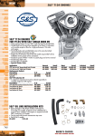
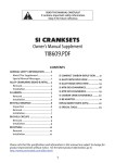
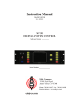
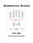
1
Chapter 1 System Description Specification 1. SCOPE This document describes the functional specifications for the Compal Notebook personal computer QAT10/11 series. The system is hardware and software compatible with the IBM PN/ATX personal computer. 1.1 Dimension 340 x 248 x 21.4mm 1.2 Weight 1.9 Kg Paint Anodize Plating VM Special texture Texture 1.3 ID 1.4 CPU Intel Ivy Bridge Dual Core i3~i7 Note: For Ivy Bridge CPU, user may experience that display showing garbage when play on-line videos such as Youtube, Youku, Tudou...etc In this situation, need update Adobe flash player later than 11.2 version from Adobe labs. More info can refer to http://labs.adobe.com/downloads/ 1.5 Chipset Intel Panther Point PCH HM77 1.6 Memory 2 x SODIMM Sockets for Expansion Up to 8GB Dual Channel DDR3 1066/1333/1600 DRAM support 1.7 Optical Device (Option) Fixed 9.5mm height SATA ODD DVD Super-Multi (DVD-RAM/-R/-RW/+R/+RW), 8X write Support Double Layer Recording is required 1.8 HDD 2.5" 9.5mm SATA HDD 320G/500G/640G/750G (5400/7200rpm) 1.9 Display 14.0“ W HD (1366 x 768) LED BL 3.6mm Panel, Dual Channel LVDS Cable HD Glare 1366 x768 1.10 Graphics Chip N/A (Just for QAT10) NVIDIA N13P-GLP upper to 2G VRAM (Just for QAT11) NVIDIA N13P-LP upper to 2G VRAM (Just for QAT11) 1.11 Audio SRS HD Audio, Speakers (2*2W), Microphone-in and Headphone-out 1.12 Communication No modem With PCI-Express No WWAN LAN: Giga LAN WLAN:802.11b/g/n,W/L+BT Combo card:802.11b/g/n+BT3.0,or 802.11b/g/n+BT4.0 1.13 Keyboard Isolated Keyboard 86/87 keys support with 101/102 key emulation without stick-point Windows key, Application key Standard pitch, 1.4+/-0.2mm travel length Multi-Language support 1.14 Pointing Device Normal Track Pad with up/down scroll zone and two buttons Support Gesture Fingerprint (Option) 1.15 Full Size Smart Card Reader Yes 1.16 Media Slot 3 in 1 Non Push-Push Type, SD+MMC+MS 1.17 I/O Ports USB: 1x USB 3.0, 2 x USB 2.0, w/ Power USB feature; RJ45 x 1 VGA port x 1 HDMI x 1 3-in-1 Card Reader x 1 Microphone-in x 1 Headphone-out × 1 TPM(Option) FP(Option) 1.18 Camera (Option) 1.0M Pixel CMOS HD Camera with LED 1.19 Microphone Analog Type Internal Microphone (On Mother Board) 1.20 System Status Indicators 1 Caps Lock (Blue) 1 Power Button LED (Blue) 1 LED for IDE HDD activity (Blue) 1 LED for Battery status (Charging / Full / L1 / L2) (Blue/Amber) 1 LED for Blue tooth/Wireless Card (Amber) 1 LED for System status (Power On / Suspend) (Blue) 1 LED for Power Saving (Blue) 1.21 Control Buttons Hot Key Power button (support software off, 4 sec)x 1 Magnetic lid switch control for system standby/ wakeup or suspend/ resume 1.22 AC Adapter 65W, 3 Pin 1.23 Battery 4cell Li-On, 18650 type, 2800mAh 1.24 Software Insyde BIOS Suspend to DRAM/HDD Security: Power-On Password, Supervisor Password USB memory Boot support Support SMBIOS 2.4, PCI2.2 Support PXE Wake on LAN from S3 Wake on LAN from S4 /S5 in AC mode USB Power Charger 1.25 OS Windows 7 Ultimate SP1 32bit / 64bit Support Windows 8(HW design ready), XP Driver ready 1.26 Security BIOS Password/Kensington lock Trusted Platform Module: TPM 1.2 (Option) 1.27 Regulatory EMI: CE,FCC,GOST,VCCI,C-Tick, BSMI Safety: UL, CB, Gost-R, CCC, SABS, BSMI Energy Star / WHQL LOGO 1.28 Environment Temperature: Operating: 5 - 35°C / Storage: -20 - 65°C Humidity: 10 - 90% without condensation 1.29 Thermal Thermal capacity could support TAT TDP% or 3Dmark2006 operation at 28C ambient. 1.30 Application Driver CD W/User Manual Chapter 2 Software Specification -1- 2.1 System Components Summary 1. Dimension 340 x 248 x 21.4mm QAT10:1880g 2. Weight 3. CPU 4. Chipset 5. Memory QAT11:1950g Intel Ivy Bridge Dual Core i3 / i5 / i7 series HM77 2 x SODIMM Sockets for Expansion Up to 8GB Dual Channel DDR3 1066/1333/1600 DRAM support Fixed 9.5mm height SATA ODD 6. Optical Device DVD Super-Multi (DVD-RAM/-R/-RW/+R/+RW), 8X write Support Double Layer Recording is required 7. HDD 2.5" 9.5mm SATA HDD 320G/500G/640G/750G (5400/7200rpm) 8. Display 14.0“ W HD (1366 x 768) LED BL 3.6mm Panel, Dual Channel LVDS Cable QAT10:N/A 9. GPU (Option) QAT11: NVIDIA N13P-GLP upper to 2G VRAM NVIDIA N13P-LP upper to 2G VRAM SRS support HD Audio 10. Audio One Audio in port One Audio out port (headphone out, no SPDIF support) Internal Microphone Synchronize to change sound output to HDMI 11. Speaker 2 stereo speakers (2W x 2) 12. Express Card Slot NA 13. Smart Card NA 14. Bridge Media Slot 3 in 1 Non Push-Push Type, SD+MMC+MS No modem 15. Communication With PCI-Express No WWAN LAN: 10/100/1000 Giga LAN WLAN: 802.11b/g/n, W/L+BT Combo card: 802.11b/g/n+BT3.0,or 802.11b/g/n+BT4.0 16. WLAN + BT Combo 17. Security 18. Internal Camera WLAN only or W/L+BT Combo BIOS Password/Kensington lock Trusted Platform Module: TPM 1.2 (Option) 1.0M Pixel CMOS HD Camera with LED Isolated Keyboard 86/87 keys support with 101/102 key emulation without stick-point 19. Keyboard Windows key, Application key Standard pitch, 1.4+/-0.2mm travel length Multi-Language support Normal Track Pad with up/down scroll zone and two buttons 20. Pointing Device Support Gesture Fingerprint (Option) USB: 1x USB 3.0, 2 x USB 2.0, w/ Power USB feature RJ45 x 1 VGA portx 1 HDMI x 1 21. I/O Ports 3-in-1 Card Reader x 1 Microphone-in x 1 Headphone-out × 1 TPM(Option) Fingerprint(Option) 22. Microphone Analog Type Internal Microphone (On Mother Board) 1 Caps Lock (Blue) 1 Power Button LED (Blue) 1 LED for IDE HDD activity (Blue) 23. System Status Indicators 1 LED for System status (Power On / Suspend) (Blue) 1 LED for Battery status (Charging / Full / L1 / L2) (Blue/Amber) 1 LED for Blue tooth/Wireless Card (Amber) 1 LED for Power saving (Blue) 24. User Keys Hot Key Power button (support software off, 4 sec) x 1 25. AC Adapter 65W, 3 Pin 26. Battery 4cell Li-On, 18650 type, 2800mAh Insyde BIOS Suspend to DRAM/HDD Security: Power-On Password, Supervisor Password USB memory Boot support 27. Software Support SMBIOS 2.4, PCI2.2 Support PXE Wake on LAN from S3 Wake on LAN from S4 /S5 in AC mode USB Power Charger 28. OS 29. Mini Card Windows 7 Ultimate 32bit / 64bit Support Windows 8 (EE design ready) 1. mSATA 2. WLAN or WLAN+BT Combo card EMI: CE,FCC,GOST,VCCI,C-Tick, BSMI 30. Regulatory Safety: UL, CB, Gost-R, CCC, SABS, BSMI Energy Star / WHQL LOGO Temperature: Operating: 5 - 35°C / Storage: -20 - 65°C 31. Environment Humidity: 10 - 90% without condensation Altitude: Operating sea level up to 10,000 ft Storage sea level up to 40,000 ft CPU Stress: 17W TDP @28C w/o throttling @ Acoustic 38dBA 1. Play DVD / Web streaming Acoustic level:32dBA 2. 3DMark06 Acoustic level:38dBA 32. Thermal Skin spec: Ta:25C P/R , Touch pad: ∆T13C K/B: ∆T15C Top skin: ∆T15C Bottom: Metal: ∆T 17C Plastic: ∆T 23C Driver CD W/User Manual WSED SRS AP BTOpm 33. Application PowerUSB cTDPHotkey(QAT10 only) TPM AP(Optional) FingerPrint AP(Optional) 2.2 System Controls 2.2.1 Buttons 2.2.1.1 Power Button The activity of the power button is as follows: If system is Off/Hibernate: System will be turned on while Power switch is depressed by more than 100 ms If system is in Standby state: System will resume while Power switch is depressed by more than 100 ms. If system on with legacy mode: depress this button will turn off power. If system is running in ACPI OS, the power button acts as the sleep button, and let OS controls the policy of power button which is defined in Power Option under the OS. 2.2.1.2 Power Button Over-ride Holding down the Power Button for 4 seconds will cause an unconditional transfer to the off state without notifying the operating system. 2.2.1.3 Lid switch If the system is running under legacy mode: Closing the lid will turn off LCD backlight. If the system is running under ACPI mode: The operating system will determine what action to take when the lid is opened and closed. The function of lid switch will follow the OS setting in power management (Nothing, Standby or Hibernate). If nothing, the backlight must turn off when the lid is closed. 2.2.1.4 System status indicators Please refer to Keyboard BIOS specification. 2.3 Core BIOS Features 2.3.1 Multi Boot The notebook can support Multi-Boot for selecting the boot sequence of Hard Drive, Removable Devices, CD-ROM/DVD Drive and Network in Setup. 2.3.2 Quiet Boot Quiet Boot replaces the customary technical messages during POST with a more visually pleasing and comfortable display (OEM screen). During POST, right after the initialization of VGA, The notebook displays an illustration called the OEM screen during system boot instead of the traditional POST screen that displays the normal diagnostic messages. The OEM screen stays up until just before the operating system loads unless: Pressing <F2> to enter Setup. Pressing <F12> to enter Boot Menu. Whenever POST detects a non-terminal error, it switches to the POST screen near the end of POST, just prior to prompting for a password. If the BIOS or an option ROM request keyboard input, the system switches over to the POST screen with prompts for entering the information. POST continues from there with the regular POST screen. 2.3.3 Boot Block The Flash ROM used in many systems today offer the customer the advantage of electronically reprogramming the BIOS without physically replacing the BIOS ROM. This advantage, however, does create a possible hazard: power failures or fluctuations that occur during updating the Flash ROM can damage the BIOS code, making the system unbootable. To prevent this possible hazard, many Flash ROM include a special nonvolatile region that can never be erased. This region, called the boot block, contains a fail-safe recovery routine. If the boot block finds corrupted BIOS, it prompts the end user to insert a diskette, from which it loads several files that replace the corrupted BIOS on the Flash ROM with an uncorrupted one. 2.4 Thermal management Please refer to Keyboard BIOS specification. 2.5 Power Management for ACPI mode 2.5.1 Introduction The notebook supports ACPI. The system will dynamically switch to ACPI mode for configuration and power management when an ACPI OS is loaded. When ACPI is not loaded and enabled, the power management function will be disabled. 2.5.2 System Time-outs If the system is running in ACPI mode, system Time-outs is handled by the operating system. BIOS time-outs are disabled. System time-outs are set using the control panel power applet. 2.5.3 System Power Management The overall system can be in one of the system power states as described below: ACPI mode Power Management Mech. Off (G3) All devices in the system are turned off completely. Soft Off (G2/S5) OS initiated shutdown. All devices in the system are turned off completely. Working (G0/S0) Individual devices such as the CPU and hard disk may be power managed in this state. S3 Sleeping State CPU set power down VGA Suspend New Card Suspend Audio Suspend Hard Disk Power Down ODD Power Down Super I/O Power Down S4 Sleeping State System Saves all system states and data onto disk prior to power off the whole system. 2.5.4 Device Power Management Under ACPI mode, the device specific power management supported by this notebook includes the CPU throttling, monitor power management and the hard disk. 2.5.4.1 CPU power management ACPI mode The operating system detects when the system is idle and places the CPU in one of the 3 CPU low power states (C1, C2, C3 up to C6) depending on how much latency it believes the system can afford. The C1 state is simply the CPU halt instruction. The C2 state is the CPU stop grant state. The C3 state is the CPU stops clock state. The CPU stays in this state until an interrupt occurs. 2.5.4.2 Hard Disk The operating system uses the spin down timer of the hard drive to set time-outs. The BIOS time-out of the hard disk must be disabled in ACPI mode. The user can sets the hard disk spin down time-out in the control panel power applet. 2.5.4.3 Display Device The monitor can be turned off after a period of no activity based on the settings of the OS. 2.5.4.4 System Wake Up Sources The table below lists the wake up events for all low power states: Events S3 S4 S5 Process required Internal Keyboard Yes No No No Internal pointing device No No No No USB No No No No Lid Switch No No No No Power button Yes Yes Yes No LAN (On board) Yes Yes(AC mode only) Yes(AC mode only) Yes RTC Yes Yes(AC mode only) Yes(AC mode only) Yes Critical low battery Yes No No Yes Field „Process required‟ identifies that further process for the occurred events must be processed during wake up or resumes procedure. 2.5.4.4.1 LAN LAN (On board) S3(Standby): LAN is supported wake-up from S3 w/ AC/DC mode S4(Hibernation)/S5: LAN just only support wake-up from S4/S5 w/ AC only BIOS will enable or disable WOL based on device manager setting. 2.5.4.4.2 Real Time Clock Alarm The Real Time Clock alarm interrupt will wake the system from Standby (DC/AC), Hibernation (AC mode only) and S5 (AC mode only). 2.5.4.4.3 Critical Low Battery Critical low battery event can wake the system from Standby (DC mode) in ACPI mode. 2.5.5 Hibernation To support the hibernate state, the save to disk partition or file will be created by the operating system if the user select to enable the hibernation. It is the responsibility of the operating system to save the system state to a disk file and restore the system state when it is turned back on. 2.6 ACPI (Advanced Configuration and Power Interface) 2.6.1 Introduction The Advanced Configuration and Power Interface (ACPI) is a well-specified power management and configuration mechanism. It evolves the existing collection of power management codes, APM, PnP BIOS, and Etc. 2.6.2ACPI Sleep Status BIOS must support the following sleep states – S3, S4 and S5. 2.6.3 Fast Resume BIOS must hands off the control to the operating system within the following time limits: Required S3->S0 2seconds *Measured using the Microsoft VTS (Velocity) tool. In addition, total resume time from S3 must be completed within 5 seconds. 2.6.4 Power State Transition Diagram The state transition diagram in ACPI mode is as follows: From (State) S3 Leave By Condition Enter (State) Power Button S0 Internal Keyboard RTC Alarm On board LAN (WOL)(*1) S3 Battery Critical Hibernation trip point reached (*2) S4 The timer timeout after the inactivity of selected timer in power scheme, System Hibernate, reaches the setting (*2) S4 Power Button S0 On board LAN (Only in AC mode) RTC Alarm(Only in AC mode) S5 Power Button S0 On board LAN (Only in AC mode) RTC Alarm(Only in AC mode) S0 Press Lid switch / Sleep Button (Fn+F2) / Power Button (depends on ACPI OS setting) User selects the Standby Option in the Windows Shut Down menu S3 ACPI OS timer expired Critical /Low battery (depends on ACPI OS setting) S0 Press Lid switch/ Sleep Button (Fn+F2) / Power Button S4 (depends on ACPI OS setting) User selects the Hibernate Option in the Windows Shut Down menu Critical /Low battery (depends on ACPI OS setting) S0 Press Lid switch / Power (depends on ACPI OS setting) Button S5 The Power Button is pressed for 4 seconds (Power Button Override) User selects the Shut down Option in the Windows Shut Down menu Critical /Low battery (depends on ACPI OS setting) Thermal critical shutdown performed by EC firmware Note1: The backlight of LCD should be off when WOL from S3 as it is remote wake up. Note2: the S3->S4 transition results in the system transitioning to the S0 state first so OS can save the context to the hard disk. The system BIOS/KBC will not be involved for S3 S4 transition. The system power scheme will wake the machine from S3 and then transition to S4 Hibernation. The backlight of LCD is off during this transition. 2.6.5 Storage Devices and Batteries Possible storage devices are FDD, HDD, CD-ROM and DVD-ROM Floppy Disk and Hard Disk, CD-ROM and DVD-ROM The BIOS must report the correct types of these devices if the drive is installed in the system during POST. Two devices, which belong to the same category, are not supported in this notebook. Batteries The BIOS must follow ACPI specification and report the correct number of the installed battery and status. 2.6.6 Bootable Device The system is capable of booting from onboard HDD, CD ROM, DVD-ROM, external USB Floppy and USB ATA Flash device. 2.6.7 Embedded controller The keyboard controller will act as the ACPI embedded controller and support the ACPI EC protocol and interface. 2.7 PC2001 The notebook must meet Microsoft Logo requirements in accordance with the PC2001 Guide and the Microsoft Logo test programs. 2.8 Miscellaneous Features 2.8.1 BIOS ROM It depends on the platform design architecture (sharer ROM or Non-Sharer ROM, Intel ME SKU and so on). Non-Sharer ROM: SBIOS and EC BIOS have each SPI ROM chip separately, the EEPROM is inside EC BIOS area, BIOS will copy a full set of EEPROM data to SBIOS ROM at the first POST or EEPROM data is updated to speed up the EEPROM access. Sharer ROM: The EC BIOS, EEPROM and SBIOS are all inside one SPI ROM chip. 2.8.2USB Support This feature allows the use of a USB keyboard to access BIOS Setup and to be used in DOS without additional drivers. USB floppy boot and Crisis Recovery from USB floppy is also supported. The driver provides other USB devices support after loading the operating system. 2.8.3 Flash utility – one ROM file only The flash utility can be used to program both system and keyboard BIOS at the same time. Before flash BIOS you must make sure that AC exist. Or you will be forbidden to flash BIOS. 2.8.4 Crisis Recovery This feature provides an opportunity for system that cannot boot up. With a crisis floppy diskette, the system can perform crisis recovery by using internal PS2 keyboard. To perform crisis recovery using keyboard, do the following: Power off the system. Plug-in the USB floppy drive with crisis floppy diskette inserted. Hold down Fn + B keys. Plug-in AC adapter and make sure it is powered. Power on the system from off state (i.e. cold boot) while holding down <Fn+B> key. After POST, release <Fn+B> key. The system should boot from floppy and perform crisis recovery action. 2.8.5 VGA Support This section describes the expected behavior when a video monitor is connected to the VGA port on the notebook .The feature needs VGA driver support. The BIOS will use both the RGB and pin 11 methods to determine the presence of an external VGA monitor. Video modes supported on the secondary display path (need VGA driver support) Supported video modes and timings please refer to the technical reference of VGA vendor. In particular, text mode and standard VGA modes are not supported. 2.8.5.1 Brightness table This section describes the LCD Brightness control. The keyboard Fn+F4 and Fn+F5 keys, the AC/DC state and the brightness slide bar in Windows Vista Mobility Center control the LCD brightness. There shall be 11 levels of distinct brightness. Level 11 = Maximum Brightness possible. Level 1 = Minimum brightness without flickering (10 nits recommended, depending on inverter stability, type and display uniformity) *One setting level should be approximately 55 – 60 nits for Mobile Mark 2002 test. 2.8.5.2 Boot Display Algorithm This section describes the POST boot up display device with multi display device attached. Only support Local Flat Panel display during POST when LFP attached, the external display device (Include VGA, DVI, HDMI and DP) will not display until entering the OS. 2.8.6 Fast Boot The BIOS POST time should be within 5 seconds or less. The BIOS POST time is measured by Microsoft Velocity Test Suite. The POST timing test needs to include the worst-case drive configuration (internal or external) and worst-case memory configuration available via the retail channels. The POST time testing environment does not include attachable devices such as USB keyboards, external monitors, printers, PC Cards, Port Replicators and etc. Note: if have TPM device, the BIOS Post Time should add extra 300 microseconds for initial. 2.8.7 Wireless Control BIOS should report the wireless device (include WLAN and BT) exist and enable status to the EC namespace for the KillSwitch support. 2.9 Customer Specific Features 2.9.1 Display of System Type and BIOS Version Number on Boot The development BIOS Version should start from 0.01 and the formal BIOS for MP should start from 1.00. 2.9.2 CMOS RAM management For UEFI Code, CMOS just reserve for kernel code/Chipset code, the variable storage had been replaced by flash part. 2.9.2.1 CMOS Requirement for Debug Purpose For debug purpose, BIOS could save data to CMOS NV0 (access by port 70h/71h) offset 48h-4Fh, 6Ch-6Fh and 70h-7Fh, NV1 (access by port 72h/73h) offset 40h-57h and 60h-7Fh which are reserved for OEM use. 2.9.3 System Management BIOS(SM BIOS) version 2.7 (DMI 2.0) Limited DMI 2.0 BIOS information is provided: BIOS version number is type 0 data item. Type 1: System serial number – 64 alphanumeric characters with 12-character bundle number System manufacturer name – 16 alphanumeric characters System product name – 32 alphanumeric characters System version – 32 alphanumeric characters UUID – 32 Hexadecimal numbers Type 2: 1 System manufacturer name – 16 alphanumeric characters 2 Motherboard Product name – „XXX‟ 3 System serial number – 64 alphanumeric characters with 12-character bundle number Type 3: 4 System manufacturer name – 16 alphanumeric character 5 System serial number – 64 alphanumeric characters with 12-character bundle number 6 Asset tag number – 128 alphanumeric characters 2.9.3.1 Default SMBIOS Value Name Default Value System Serial Number 123456789 Manufacturer name Compal System version X.XX System product name %project code% 2.9.4 EEPROM There is one EEPROM that is used to store many important system and user data in the notebook (some data are reserved for future to use)). The size of the EEPROM is 2K bytes. The EEPROM map is listing as below: Name Offset Comments System Serial Number 00h – 1Fh 32 bytes of Serial number. 20h – 3Fh 32 bytes of Bundle number. Manufacturer name 40h – 4Fh 16 bytes for DMI type 1/2/3 System version 50h – 6Fh 32 bytes of System version for DMI type 1. UUID 70h – 7Fh 16 bytes for UUID for DMI type 1. System product name 80h – 9Fh 32 bytes of System product name. DMI type 11 A0h – DDh 62 bytes for DMI type 11 OS_SKU DEh 1 byte for OS type Unused DFh Unused GUID E0h – E7h 8 bytes for GUID Born On Date E8h – EAh 3 bytes for born on date EEPROM initialized flag EBh Set to AAh when the EEPROM get initialized. Reserved ECh - EFh Reserved Keyboard type F0h Define for US/UK/JP keyboard Keyboard BIOS used F1h 1 byte for Keyboard BIOS used Branding F2h 1 byte for Branding. TFYJ F3h 1 byte for TFYJ KMS F4h KMS active flag Reserved for keyboard F5h – F6h Reserved 2 bytes for keyboard used Unused F7h – FEh Unused Assettag number 200h – 23Fh 64 bytes for DMI Type 3 LAN MAC Address 240h – 245h 6 bytes for LAN without EEPROM Unused 246h – 25Fh Unused ACPI OEM ID 260h – 265h 6 bytes for ACPI OEM ID Unused 266h – 26Fh Unused ACPI OEM Table ID 270h – 277h 8 bytes for ACPI OEM Table ID Reserved 278h - 7FFh Reserved 2.9.5 OEM Active 1.0/2.0/2.1 and KMS activation Support OEM Activation 1.0 (a.k.a. SLP 1.0) is used to activate Windows XP. To support it, BIOS needs to populate OEM string in the 0xF000 segment during POST. OEM Activation 2.0 (a.k.a. SLP 2.0) is used to activate Windows Vista. To support it, BIOS needs to populate ACPI SLIC table during POST. For projects supports Windows 7, SLP 2.1 is required to support. MS claims the Windows marker is MS‟s IP and cannot appear on non-Windows OS SKUs. An EEPROM flag OS_SKU (refer Sec. 4.10.4) is defined to indicate the machine is shipped with Windows or non-Windows OS. The flag is programmed in the factory and BIOS needs to read this flag when populating OEM string/ACPI SLIC table. If the flag indicates the machine is shipped with non-Windows OS, BIOS will not load Windows marker structure in ACPI SLIC table. KMS Activation support. To support the KMS activation, the SLIC table should be removed from the ACPI table. To support multi customer, BIOS should remove the SLIC table as default, and populate the SLIC table if customer enter the OEM ID, OEM table ID and OS_SKU in the EEPROM. The customer should create customized BIOS with SLP2.0/2.1 market and public key at the same time to active Vista/Window 7. Please refer to the “How to update OEM SLP” for the detail instruction of customized BIOS creation. 2.9. 6 Multi Customer Logo Support To support Multi customer Logo, BIOS will merge dummy OEM logo in BIOS as default, and customer should create customized BIOS with OEM Logo. Please refer to the “How to update OEM Logo” for the detail instruction of customized BIOS creation. 2.10 System Setup 2.10.1 Invoking setup The setup function can be invoked by pressing F2 when “Press <F2> to enter Setup” message is prompted on the bottom of screen during POST. During setup, all Fn function keys and power saving functions are disabled. 2.10.2 Main Menu InsydeH20 Setup Utility Main Advanced Security Boot Exit System Time [00:00:00] System Date [01/01/2011] Processor Type Type,XXXGHZ System Memory Speed XXXMHz Total Memory XXX MB EC version X.XX System BIOS Version X.XX.XX Intel ME Version X.X.XX.XXXX HDD Disk0 XXXXXX CD/DVD Rom XXXXXX Details see the following Serial Number Help Information XXXXXX UUID F1 Help Esc Exit Select Menu Select Item F5/F6 Change Values F9 Setup Defaults Enter Select SubMenu F10 Save and Exit System Time and System Dat The hour is displayed with 24-hour format. The values set in these two fields take effect immediately. Processor Type This field shows CPU type and speed. System Memory Speed This field reports the memory speed of the extended memory with an integer in the system Total Memory This field reports the memory size of the extended memory with an integer in the system. HDD Disk This field reports the HDD string. CD/DVD Rom This field reports the CD/DVD string. Serial Number This field displays the serial number, max size support to 32 bytes. UUID This field display the UUID, the length is 16 bytes. Help information System Time [hh:mm:ss]This is the help for the hour field. Vaild range is from 0 to 23. INCREASE/REDUCE:+/-. [hh:mm:ss]This is the help for the minute field. Vaild range is from 0 to 59. INCREASE/REDUCE:+/-. [hh:mm:ss]This is the help for the second field. Vaild range is from 0 to 59. INCREASE/REDUCE:+/-. System Date [mm:dd:yy]This is the help for the month field. Vaild range is from 1 to 12.(Error checking will be done against month/day/year combinations that are not supported.) INCREASE/REDUCE:+/-. [mm:dd:yy]This is the help for the day field. Vaild range is from 1 to 31.(Error checking will be done against month/day/year combinations that are not supported.) INCREASE/REDUCE:+/-. [mm:dd:yy]This is the help for the year field. Vaild range is from 2000 to 2009.( Error checking will be done against month/day/year combinations that are not supported.) INCREASE/REDUCE:+/-. 2.10.3 Advanced InsydeH20 Setup Utility Main Advanced Security Num lock Boot Exit <Off> ►Peripheral Configuration VT <Enabled> Configuration SATA as <AHCI> POST Hotkey Delay <0> UMA Share Memory Size <32MB> USB Legacy <Enabled> Power USB <Disabled> Battery Mode Support <Capacity>=20%> Details see the following Help Information ►INTEL Anti-Theft Technology Configuration ►INTEL(R) Rapid Start Technology F1 Help Esc Exit Select Menu Select Item F5/F6 Change Values F9 Setup Defaults Enter Select SubMenu F10 Save and Exit Numlock Enter this menu, you can choose the ON or Off in this submenu. Peripheral Configuration Enter this menu, it can display the submenu: “Bluetooth <Enable>” “Wlan <Enable>” “Camera <Enable>” “Card Read <Enable>” “Azalia <Auto>” You can select Enabled or Disabled in the above submenu, and in the submenu “Azalia <Auto>” you also can select Auto, Enable or Disable. Configuration SATA as Choose HDD mode through selecting the IDE mode or AHCI mode or RAID mode. VT You can select the Disabled or Enabled in this menu. UMA Share Memory Size You can select the share memory size for UMA use, 32MB/64MB/128MB could be selected. USB Legacy You can select the Disabled or Enabled in this menu according to the owner requests. Power USB You can select Enabled to charge USB device via USB ports. Power USB also can support battery mode if battery capacity >= N%. Battery Mode Support Select capacity >= N% or disable battery mode. You only can select capacity or disable Battery Mode Support after the Power USB is enabled. INTEL Anti-Theft Technology Configuration Enter this menu, it can display the submenu: “Intel(R) AT Support System “Intel(R) AT Recovery <Enabled>” [3]” You can select the Disabled or Enabled in the above submenu. Set the number of times Intel(R) AT Recovery attempts will be allowed. INTEL(R) Rapid Start Technology Enter this menu, it can display the submenu: “iRST Support <Disabled>” You can select the Disabled or Enabled in the above submenu. “Entry after 10 minutes” The timer setting to entry iRST, Immediately/1 minute/2 minutes/5 minutes/10 minutes/15 minutes/30 minutes/1 hour/2 hours/12 hours/24 hours could be selected after enable iRST. Help information: NumLock Selects Power-on state for Numlock. Peripheral Configuration Configures the peripheral devices. Bluetooth/Wlan/Camera/Card Read/Azalia Enable or Disable this device, and in the submenu [Azalia <Auto>] you also can select Auto, Enable or Disable. VT Virtualization Technology Enable/Disable. Configure SATA As Set Harddisk Controller Configure Type. POST HotKey Delay Customizable amount of time for the user to press HotKey at POST. UMA Share Memory Size Select DVMT5.0 Pre-Allocated(Fixed) Graphics Memory size used by the Internal Graphics Device. Usb Legacy USB devices boot and access in DOS. If disable USB Legacy, USB devices can not boot. FAST Boot This BIOS POST time will be within 2 seconds or less when Fast boot enable. Power USB Power USB Function Enable/Disable. INTEL Anti-Theft Technology Configuration Disabling Intel(R) AT Allow user to login to platform, this does not disable Intel(R) AT services in ME. Intel(R) AT Support System Enable/Disable Intel(R) Anti-Theft Technology Intel(R) AT Recovery Set the number of times Intel(R) AT Recovery attempts will be allowed INTEL(R) Rapid Start Technology iRST Settings 2.10.4 Security Menu This menu shows the security setting, such as TPM, User and Supervisor Password, HDD Password and Power on Password. InsydeH20 Setup Utility Main Advanced Security Boot Exit TPM Status XXXXX TPM Operation [No Operation] TPM Force Clear [Disabled] Details see the following Help Information Supervisor Password Clear Set Supervisor Password Power on Password [Disabled] F1 Help Esc Exit Select Menu Select Item F5/F6 Change Values F9 Setup Defaults Enter Select SubMenu F10 Save and Exit TPM Status Show the TPM status: “Enable and Active” or “Disable and Deactive”. This option only show on TPM unit. TPM Operation Enable/Disable TPM Function. This option will automatically return to No-Operation. This option only show on TPM unit. TPM Force Clear This item will show when the TPM Operation be set “Enable and Active”, used to enable/disable TPM Force Clear function. This option only show on TPM unit. Supervisor Password Show the Password status: Clear or Set Set Supervisor Password Install or Change the password. Power on Password Enable or disable the Power on Password. You only can enable/disable Power on password after the Supervisor password is set. Help information TPM Operation Enable/Disable TPM function. This option will automatically return to NO-Operation. TPM Force clear TPM Force Clear function. Set Supeivisor Password Install or change the password and the length of password must be greater than one character. Set Supervisor Password Install or change the password and the length of password must be greater than one character. Power on password Enable: System will ask input password on post time. Disable: System will ask input password when go to Setup Utility Password behavior Supervisor Password and Power on Password After set the supervisor password, power on password can enable or disable. If only set the supervisor password, system will request supervisor password before entering setup menu(F2). Users have 3 chances to input supervisor password, system will request shutdown if users input wrong password 3 times. If set power on password, system will request the password after power on the machine . Users have 3 chances to input power on password, system will request shutdown if users input wrong password 3 times. 2.10.5 Boot Menu This menu allows the user to decide the order of boot devices to load the operating system. Bootable devices include the diskette drive in module bay, the onboard hard disk drive in module bay. InsydeH20 Setup Utility Main Advanced Security Boot Exit Boot priority order: Floppy Drive : XXXXXXXXXX Hard Disk Drive0 : XXXXXXXXXX Hard Disk Drive1 : XXXXXXXXXX CD/DVD-ROM Drive: XXXXXXXXXXX USB HDD : XXXXXXXXXX USB CDROM : XXXXXXXXXX Network boot: XXXXXXXXXX Boot Device Status: Floppy Drive <Enabled> CD/DVD-ROM Drive <Enabled> Network boot <Enabled> Details see the following Help Information F1 Help Esc Exit Select Screen Select Item F5/F6 Change Values F9 Setup Defaults Enter Select SubMenu F10 Save and Exit Help information Use <>or <¯> to select a device, then press <F5> to move it down the list, or <F6> to Move it up the list. Press <Esc> to escape the menu. 2.10.6 Exit Menu InsydeH20 Setup Utility Main Advanced Security Boot Exit Exit Saving Changes Exit Discarding Changes Load Optimal Defaults Details see the following Help Information F1 Help ↓Select Item Esc Exit ←→Select Menu F5/F6 Change Values Enter Select SubMenu F9 Setup Defaults F10 Save and Exit Exit Saving Changes Allows the user to save changes to NV Storage and reboot system. The following message is prompted when user press “Enter” on the item. Exit Saving Changes? [Yes] [No] Yes: Save Changes, Exit SETUP and reboot No: Back to previous screen Exit Discarding Changes Allows the user to discard changes and continue the boot operation. The following message is prompted when user press “Enter” on the item. Exit Discarding Changes? [Yes] [No] Yes: Discard Changes and Continue the boot operation. No: Back to previous screen Load Optimal Defaults Allows the user loads default value in CMOS Setup. The following message is prompted when user press “Enter” on this item: Load Optimal Defaults? [Yes] [No] It still stay in Setup when press a key. Help information Exit Saving Changes Exit system setup and save your changes. Exit Discarding Changes Exit system setup and without saving your changes. Load Optimal Defaults Load Optimal Defaults. 2.11 OS Compatibility Windows 7 (32bits and 64bits) Chapter 3 Hardware -1- 1. Major Sub-assembly Specification System interconnection 1.1 Top View (For QAT10 /11) NO Description 1 MIC Conn 2 K/B Conn 3 ODD Board Conn 4 Finger Print Conn 5 TP Conn 6 Multi-function Board Conn 7 3in1 card Conn 8 Speaker Conn 9 10 LVDS Conn Power Board Conn 1.2 Bottom view (For QAT10 /11) -2- NO Description NO Description 11 VGA Connecter 12 RJ45 Connecter 13 HDMI Connecter 14 USB3.0 Connecter 15 DDR3.0(H=4.0) Socket 16 DDR3.0(H=4.0) Socket 17 Speaker Connecter 18 HDD Cable Connecter 19 MINI Card Socket 20 MINI Card Socket 21 Battery Connecter 22 DC-IN Connecter 23 Fan Connector 24 25 -3- 26 Chapter 4 DC-DC CONVERTER 4.1 Description -1- The DC-DC converter is designed to supply the power for QAT10/11 series ultrabook of Compal. It supply +5VALWP, +3VALWP, +1.5VP, +1.05VSP, +1.8VP, +VCCSAP, +0.75VSP, +1.05V_MP, for logical system, +CPU_CORE for CPU and supplies +3VL for the built-in KB9012 microprocessor which handles the keyboard and PMU control functions of the system. The power ON/OFF is controlled by KB9012. There is also a built-in charger power source. It can charge battery pack whether the computer is ON or OFF. Features: 4.2.1.1 High efficiency, up to 85% (using battery) 4.2.1.2 Accept wide range DC input voltage from 9V to 19V 4.2.1.3 Built-in charger power source 4.2.1.4 The power ON/OFF is controlled by software 4.2.2 Electrical specification 4.2.2 Input Voltage/Current 4.2.2.19V to19V at the summing point of AC-DC and battery 4.2.2.2 INPUT Current 5.2A max from 9-cell battery 4.2.2.3 3.42 A max from 65W AC-DC Adapter for QAT10/11. 4.3 Temperature Range: 4.3.1.1 Operating temperature: -10 C to 85 C 4.3.1.2 Storage temperature range: -40 C to 150 C DC/DC OUTPUT 4.3.1.3 Fixed output voltage/Current Item +5VALWP +3VALWP +1.5VP nominal voltage +5V +3.3V +1.5V min. current 0A 0A 0A max. current 9.45A 4.2A 9.1A peak current 13.5A 5.71 A 13A total regulation 5V±5% 3.3V±5% 1.5V±5% ripple voltage 100mVp-p max. 66mVp-p max. 30mVp-p max Item +1.05VSP +1.8VSP nominal voltage +1.05V +1.8V min. current 0A 0A 0A max. current 9.45A 2A 6A peak current 13.5A 4A 7.2A total regulation 1.05V±5% 1.8.V±5% 0.9 V±5% ripple voltage 21mVp-p max. 36mVp-p max. +VCCSAP .9V 18 mVp-p max Item +0.75VSP nominal voltage +0.75V +1.05V_MP +1.05V min. current 0A 0A max. current 1.5A 1.3A peak current 2.1A 1.8A total regulation ripple voltage Item 0.75V±5% 15mVp-p max. +CPU_CORE nominal voltage +0.3~+1.35V 1.05V±5% 21mVp-p max. +GFX_CORE +0~+1.3V min. current 0A 0A max. current 33A 18A peak current 45A 33A total regulation Follow Intel spec Follow Intel spec ripple voltage Follow Intel spec Follow Intel spec +VGA_CORE (QAT11 only) 0~+0.95V 26.5A 34A ID ±100mV ID ±2.5% OVER Current protection: +5VALWP: 20A +3VALWP: 11.6A +1.5VP: 20.4A +1.05VSP: 22.8A +1.8VSP: 5.68A +VCCSAP: 8.2A +0.75VSP 2.5A +1.05V_MP 2.1A +CPU_CORE: 49.5A (min.) +GFX_CORE: 49.5A +VGA_CORE: 38A(min.) OVER Voltage protection: +5VALWP: 5V *(108% ~ 115%) +3VALWP: 3.3V *(108% ~ 115%) +1.05VSP: 1.05V*(115% ~ 125%) +1.5VP: 1.5V*(118% ~ 122%) +1.8VSP: 1.8V*103% +VCCSAP: VID*(117%~123%) +0.75VSP 0.75V*103% +1.05V_MP 1.05V*103% +GFX_CORE: Over 225~275 mV of programmed VID level +CPU_CORE Over 225~275 mV of programmed VID level +VGA_CORE: Over 150~240 mV of programmed VID level Under voltage protection +5VALWP: 5V *(65% ~ 75%) +3VALWP: 3.3V *(65% ~ 75%) +1.05VSP: 1.05V*(65% ~ 75%) +1.5VP: 1.5V*(60% ~ 80%) +1.8VSP: 1.8V*67% +VCCSAP: VID*(65%~71%) +0.75VSP 0.75V*67% +1.05V_MP 1.05V*67% +GFX_CORE: Under 350~450mV programmed VID level +CPU_CORE Under 350~450mV programmed VID level +VGA_CORE: Under 235~355mV programmed VID level Short circuit protection: Latch mode for +5VALWP, +3VALWP, +1.5VP, +1.8VSP, +VCCSAP, +1.05VSP, +0.75VSP, +1.05V_MP, +CPU_CORE, +GFX_CORE I/O 4.4.1 DC-Jack Pin 1: Center pin Adapter power +input Pin 2: Barrel (Ring) Adapter power return 4.4.2 Interface between Power with M/B DC/DC Signals I/O Voltage Level Description SUSP# I 0~3.3V Low Active, system suspend control signal ADP_I I 0~3.3V Analog signal, KBC9012 uses this voltage level to calculate CP EC_ON I 0~3.3V High Active, turn on/off 3/5VALWP ACIN O 0~3.3V High Active, provide to KB9012 to mean the Adaptor power is present VGATE O 0~3.3V High Active, it will go high when +CPU_CORE is ready VR_ON I 0~3.3V High Active, turn on/off the +CPU_CORE & GFX_CORE BATT_TEMP O 0~3.3V Analog signal, KB9012 using this voltage level to calculate battery’s temperature EC_SMDA, EC_SMCA Interface of Smbus, communicate between KB9012 and smart battery I/O 0~3.3V SYSON I 0~3.3V High Active, KB9012 use this pin to control the SYSON signal VR_SVID_D AT I 0~1.05V VR_SVID_C LK I 0~1.05V VR_SVID_A LRT# I 0~1.05V Control +CPU_CORE/+GFX_CORE regulator. Control +CPU_CORE/+GFX_CORE regulator. Control +CPU_CORE/+GFX_CORE regulator. Battery 4.5.1 Charger 1...1 Controlled by KB930 microprocessor from motherboard. 1...2 Temperature sense capability for the battery (charge active between 0C~ 50C) 1...3 Fast charge current 1.96 Amps(max.) for Li-Ion Battery at system off, approach 29W fast charge at system ON. (depend on system load) 1...4 Trickle charge: Typical 500mA pre-charge current for Li-Ion Battery . All trickle charge are controlled by KB930. 1...5 Charge termination: When Fully-Charge bit is set ,charger is terminated by KB930 1...6 When system is turned off, the charge time is 3.0 hrs typically from empty to full. 1...7 Other battery services are presented by KB930 microprocessor includes maximum charging timer, charging temperature range etc. 1...8 Charger power: 1...8.1 Constant current mode: 1.96A 1...8.2 Constant adapter current mode: 2.91 (For 65W system) 1...8.3 BATT+ Constant Voltage mode: 17.2V 4.5.2 BATTERY Specification 1.1 EE information 4 cell Battery Design Capacity(mAH) Battery Configuration Battery Nominal Voltage(V) Single Cell Chemistry Single Cell Type Single Cell Capacity(mAH) Dumb/Smart Battery Cycle Life Nominal Charging Voltage(V) Nominal Charging Current(A) Protection Function 2800 4S1P 14.8 Li-ion 18650 2800 Smart Battery (SMBus ver. 1.1.) 90% after 300 cycles 17.2 1.96 OVP UVP OTP OCP 1-2 Battery Connector Pin Assignment Note: 1. ID pin must floating 2. The battery can be charged/discharged only while this pin is connected to GND by the system. 3. Thermister: BM22-3H103FB-025. The other thermister Pin is connected GND. Modularized battery pack, easy to be replaced. On board RTC battery: MAXELL ML1220HT10 3V MAXELL ML1220T10 PANASONIC ML-1220/F1B 3V 17mAH Li-ion primary battery FDK ML1220-TT28 3V 15 mAH Li-ion primary battery 3V 18 mAH Li-ion primary battery 14 mAH Li-ion primary battery 1.3 CAUTION Danger of explosion if battery is incorrectly replaced. Replace only with the same or equivalent type recommended by the manufacturer. Dispose of used batteries according to the manufacturer’s instructions. 4.6 Adapter Electrical Specification 65W 1 Scope This specification describes the physical, functional and electrical characteristics of the 65 watts, single output 19Vdc/3.42A, switching power supply. 2 Power nput: 2.1 Input voltage range : 90~264 Vac 2.2 Input frequency range : 47~63 Hz 2.3 Inrush Current No damage; meet fuse and bridge diode I²t de-rating specified 2.4 Input current : Max at 100Vac input voltage. 3 Power Output 3.1 Leakage Current The AC leakage current is less than 75μA when adapter is connected to 240Vac/50Hz at normal condition. 3.2 Hold up time The output voltage shall be sustained 5mS within regulation requirement after loss 100Vac and maximum load. 3.3 Turn on time The Adapter shall switch on in less than 2 seconds at input voltage is 100Vac. 3.4 Rise time DC output rise time from 10% to 90% of output voltage shall be less than 100ms at nominal line and maximum load. 3.5 Over shoot The output overshoot shall be less than 20.5V 3.6 Ripple & Noise Output ripple voltage is 380 mV peak to peak or less. 3.7 Protection 3.7.1 Over current protection The adaptor shall be auto-recovery at over-current condition , OCP must be more than 4.1A. 3.7.2 Over voltage protection The output shall be protected to latch off at over-voltage condition, maximum value can’t be over 27V. That might be return to normal state by AC reset . 3.7.3 Short circuit protection Output can be shorted without damage. The adaptor shall be auto-recovery. (It will enter into normal condition when the fault condition is removed.) 3.7.4 Over temperature protection No deformation and no discoloration on case and will be shut down. The case temperature < 95Deg C. That will be return to normal state by ac reset. 4.1 Efficiency 4.1.1 84 % min. at nominal input voltage, maximum load and measured at the end of DC cable. 4.1.2 Active mode efficiency: More than 87% of average efficiency of 25%,50%,75% and 100% load tested at 115Vac and 230Vac. (Warm up after 30 minutes) 5. ENVIRONMENTAL REQUIREMENTS 5.1 TEMPERATURE Operating: 0 to 40 degrees C. Non-operating: -20 to 85 degrees C. 5.2 HUMIDITY 8% to 90% relative humidity, non-condensing during operating temperature. 5% to 90% relative humidity, including condensation during non-operating temperature. Chapter 5 Disassembly Guide 1. Disassembling the Base Unit These are the directions for disassembling the base unit. You will need a 5.5mm Nut Driver, a medium size Philips screwdriver. These directions are to disassemble the complete unit and are cross-referenced to Chapter 7 for the replacement of component parts. Before disassembly, make sure the notebook is powered off. 1.1 upper and lower disassemble 1.1.1 Disassemble battery 、thermal door and HDD door; (take off 7 pcs screw) follow the steps below: Turn the notebook upside down. Slide the battery lock to unlock the battery pack. Slide the battery release latch in the direction of the arrow; gently pry the battery pack from its housing. NOTE: Always start laptop disassembly by removing the battery pack first. Follow the steps below to remove the thermal door: Turn the notebook upside down. Remove the 1 screws securing the bottom cover. 1.1.2 Take off ODD screw ;( take off 1pcs screw) Disassemble ODD and HDD module 1.1.3 Disassemble RAM; 1.1.4 Disassemble WLAN card and SSD (take off 4 screws). 1.1.5 Pull out Speaker cable 1.1.6 Take off 14 screw on lower as below: 1.1.7 turn over computer ,disassembled K/B. 1.1.8 Disassemble upper ; 1.1.9 Disassemble power board on Upper (take off 1 screw). 1.1.10 Disassemble Microphone and TP Cable 1.1.11 Disassemble M/B (take off 2 screws). 1.1.12 Take off Speaker&USB/B&ODD/B (take off 5 screws). 1.1.13 Take off Thermal module ( take off 6 screws ) 1.1.14 Separation of LCD and Lower ( take off 2 screws ) 1.2 LCD Part 1.2.1 Disassemble LCD bezel; 1.2.2 Disassemble panel(take off 4 screws) 1.2.3 Disassemble W/L Cable&camera&Hinge(take off 4 screws). 1.3 ODD module disassemble 1.3.1 ODD disassemble (Remove 2 screws) Chapter6 Testing and Troubleshooting The purpose of this chapter is to provide a systematic method of isolating problems you may have with the QAT10 and QAT11 series Notebook Computer. We assume that you have a basic understanding of DOS-based computer systems as well as knowledge of standard troubleshooting procedures. This manual is written under the assumption that the problems are indeed related with Notebook itself. The improper usage and application software problems are excluded in this chapter. The system BIOS Beep Code is an integrated unit to detect some errors in the system board. This beep code will give immediate identification of certain system board problems. If the troubleshooting procedure is followed step by step, it can efficiently isolate the problem and the problem can be solved easily. 1.1 PERFORM VISUAL INSPECTION Check the following: Power cords are properly connected and secured Power supply is adequate for operation There are no obvious shorts or opens There are no obviously burned or heated components All components appear normal 1.2 Troubleshooting Flowchart Use the flowchart in Figure 6-1 as a guide for determining which troubleshooting procedures to execute. Before going through the flowchart steps, verify the following: Ask the user if a password is registered and, if it is, ask him or her to enter the password. Verify with the customer that Win7 or Win8 is installed on the hard disk. Operating systems that were not preinstalled by Compal can cause the computer to malfunction. Make sure all optional equipment is removed from the computer. Make sure the floppy disk drive is empty. 8 Figure 6-1 Troubleshooting flowchart (1/2) Figure 6-1 Troubleshooting flowchart (2/2) 10 If the diagnostics program cannot detect an error, the problem may be intermittent. The test program should be executed several times to isolate the problem. When a problem has been located, perform the appropriate troubleshooting procedures as follows: If an error is detected by the main battery test, perform the Power Supply Troubleshooting procedures in Section 6-2. If an error is detected by the display test, perform the Display Troubleshooting procedures in Section 6-3. If an error is detected by the keyboard test, perform the Keyboard Troubleshooting procedures in Section 6-4. If an error is detected when using an external USB device, perform the External USB Devices Troubleshooting procedures in Section 6-5. If an error is detected when using the CRT connection, perform the CRT Failure Troubleshooting procedures in Section 6-6. If an error is detected when using the HDMI connection, perform the HDMI Failure Troubleshooting procedures in Section 6-7. If an error is detected when using the touch pad, perform the Touch Pad Troubleshooting procedures in Section 6-8. If an error is detected when using the speakers, perform the Speaker Troubleshooting procedures in Section 6-9. If an error is detected when using the CD/DVD drive, perform the CD-ROM/DVD Drive Troubleshooting procedures in Section 6-10. If an error is detected when using the Wireless LAN unit, perform the Wireless LAN Troubleshooting procedures in Section 6-11. If an error is detected when using the Camera, perform the Camera Troubleshooting procedures in Section 6-12. If an error is detected when using the Bluetooth, perform the Bluetooth Troubleshooting procedures in Section 6-13. 2. Power Supply Troubleshooting Figure 6-2 Power Supply Troubleshooting Process 12 The power supply controls many functions and components. To determine if the power supply is functioning properly, start with Procedure 1 and continue with the other Procedures as instructed. The flowchart in Figure 6-2 gives a summary of the process. The procedures described in this section are: Procedure 1: Power status check Procedure 2: Adaptor / battery replacement Procedure 3: Power supply connection check Procedure 4: Diagnostic check Procedure 5: Internal connection check Procedure 1 Power Status Check The following LEDs indicate the power supply status: Battery LED The power supply controller displays the power supply status through the Battery and the POWER LEDs as listed in the tables below. Table 2-1 Battery LED Battery State LED colors Charging Amber, solid on blue, solid on color off Discharging Definition Battery charging with AC Battery fully charged by AC Battery abnormal: stop charging with AC (Bad cell/ Overheated) Amber, blinking Battery within low state (1 second The system is protected and cannot be reon/1second off) powered on without the AC power connected. Amber & Blue, Battery error blinking (Flash 500ms on/500ms off) Color off Battery not in low or critical low state; in discharging state Table 2-2 POWER LED Power supply status System Power On (Power button LED is solid white, Power LED is solid blue). System Suspended POWER LED White Solid on Blue Solid on White blinking Blue blinking System Power Off. Off To check the power supply status, install a battery pack and connect an AC adaptor to the DC-IN port on the computer and to a power supply. If the Battery LED is not lit, go to Procedure 2 Procedure 2 Adaptor / battery replacement A faulty adaptor may not supply power or may not charge the battery. Perform Check 1. Check 1 Connect a new AC adaptor. If the problem is not resolved, go to Check 2. Check 2 Insert a new battery. If the problem is still not resolved, go to Procedure 3. Procedure 3 Power supply connection check The power supply wiring diagram is shown below: Any of the connectors may be disconnected. Perform Check 1. Check 1 Disconnect the AC power cord from wall outlet. Check the power cable for breaks. If the power cord is damaged, connect a new AC power cord. If there is no damage, go to Check 2. Check 2 Make sure the AC adaptor cord and AC power cord are firmly plugged into the DC-IN socket, AC adaptor inlet and wall outlet. If these cables are connected correctly, go to Check 3. Check 3 Make sure that the DC-IN input port socket is firmly secured to the system board of the computer. If the DC-IN input socket is loose, go to Procedure 5. If it is not loose, go to Check 4. Check 4 Use a millimeter to make sure that the AC adaptor output voltage is close to 19 V. If the output is several percent lower than 19 V, go to Check 5. If the output is close to 19 V, go to Check 6. 14 Check 5 Connect a new AC adaptor or AC power cord. If the battery LED does not light, go to Check 6. Check 6 Make sure the battery pack is installed in the computer correctly. If the battery is properly installed and the battery LED still does not light, go to Procedure 4. Procedure 4 Diagnostic check The power supply may not charge the battery pack. Perform the following procedures: Reinstall the battery pack. Attach the AC adaptor and turn on the power. If you cannot turn on the power, go to Procedure 5. Run the Diagnostic test following the procedures described Tests and Diagnostics. If no problem is detected, the battery is functioning normally. Procedure 5 Replacement check The system board may be disconnected or damaged. Disassemble the computer following the steps described Replacement Procedures. Check the connection between the AC adaptor and the system board. After checking the connection, perform Check 1: Check 1 Use a millimeter to make sure that the fuses on the system board are not blown. If a fuse is not blown, go to Check 2. If a fuse is blown, go to Check 3. Check 2 Make sure that the battery cable is firmly connected to the system board. If it is connected firmly, go to Check 3. Check 3 The system board may be damaged. Replace it with a new one following the instructions in Chapter 4. Display Troubleshooting Figure 6-3 Display troubleshooting process 16 This section describes how to determine if the computer‟s display is functioning properly. The process is outlined in Figure 6-3. Start with Procedure 1 and continue with the other procedures as instructed. Procedure 1: Procedure 2: Procedure 3: Procedure 1 External display check Diagnostic check Connector and replacement check External display check Connect an external display to the computer‟s external monitor port, then boot the computer. The computer automatically detects the external display. Press Fn+F3 to switch to the external display. If the external display works correctly, the internal LCD may be damaged. Go to Procedure 3. If the external monitor appears to have the same problem as the internal monitor, the system board may be damaged. Go to Procedure 2. Procedure 2 Diagnostic check The Display Test program is stored on the computer‟s Diagnostics disk. This program checks the display controller on the system board. Insert the Diagnostics disk in the computer‟s floppy disk drive, turn on the computer and run the test. Refer to Chapter 3, Tests and Diagnostics for details. If an error is detected, go to Procedure 3. If an error is not detected, the display is functioning properly. Procedure 3 Connector and replacement check The FL inverter board, LCD module, and system board are connected to the display circuits. Any of these components may be damaged. Replacement Procedures, for instructions on how to disassemble the computer and then perform the following checks: Check 1 Make sure the DDRRAM module is seated properly. Test display again. If the problem still exits, replace the DDRRAM module. If the problem still exists, perform check 2. Check 2 Replace the FL inverter board with a new one and test display again. If the problem still exists, perform Check 3. Check 3 Replace the LCD module with a new one and test display again. If the problem still exists, perform Check 4. Check 4 Replace the LCD/FL cable with a new one and test display again. If the problem still exists, perform Check 5. Check 5 Replace the CPU with another of the same specifications. If the problem still exists, perform Check 6. Check 6 The system board may be damaged. Replace it with a new one. Keyboard Troubleshooting Figure 6-4 Keyboard troubleshooting process 18 To determine if the computer‟s keyboard is functioning properly, perform the following procedures. Figure 6-5 outlines the process. Start with Procedure 1 and continue with the other procedures as instructed. Procedure 1: External keyboard check Procedure 2: Diagnostic check Procedure 3: Connector and replacement check Procedure 1 External keyboard check Connect a USB keyboard to one of the computer‟s keyboard/mouse ports, then boot the computer. The computer automatically detects the external keyboard. If the external keyboard works correctly, the internal keyboard or its connections may be faulty. Go to Procedure 2. If the external keyboard appears to have the same problem as the internal keyboard, the system board may be damaged. Procedure 2 Diagnostic test Run the Diagnostic Program, which will automatically execute the Keyboard Test. Refer to Chapter 3, Tests and Diagnostics for more information on how to run the program. If an error is located, go to Procedure 3. If an error does not occur, the keyboard is functioning properly. Procedure 3 Connector and replacement check The keyboard and/or system board may be disconnected or damaged. Replacement Procedures and perform the following checks. Check 1 Make sure the keyboard cable is firmly connected to the system board. If the connection is loose, reconnect firmly and repeat Procedure 2. If there is still an error, go to Check 2. Check 2 The keyboard may be damaged. If the problem still exists, perform Check 3. Check 3 The system board may be damaged. Replace it with a new one. External USB Devices Troubleshooting Figure 6-5 External USB device troubleshooting process 20 To determine if the computer‟s external USB devices are functioning properly, perform the following procedures. Figure 6-5 outlines the process. Start with Procedure 1 and continue as instructed. Procedure 1: Procedure 2: Procedure 1 External device and connection check Replace system board External device and connection check The USB device may be damaged or the connection may be faulty. Perform Check 1. Check 1 Make sure USB device cable is firmly plugged into one of the USB sockets. If the cable is connected correctly, go to Check 2. Check 2 Plug the USB device into another USB socket (there are three in all). If the USB device still does not work, go to Check 4. If the device functions correctly when connected to another USB port, go to Check 3 Check 3 Make sure that the USB socket is firmly secured to the system board of the computer. If the malfunction remains, the system board may be damaged. Go to Procedure 2. Check 4 Connect an alternative USB device to one of the computer‟s USB ports, and then boot the computer. The computer automatically detects the external device. If the alternative USB device works correctly, the original device may be damaged and should be replaced. If the alternative USB device appears to have the same problem as the original device, the system board may be damaged. Go to Procedure 2. Procedure 2 Replace system board If the error persists, the system board may be damaged. CRT troubleshooting Figure 6-6 CRT troubleshooting process 22 To determine if the computer‟s CRT port is functioning properly, perform the following procedures. Figure 6-6 outlines the process. Start with Procedure 1 and continue as instructed. Procedure 1: CRT connection check Procedure 2: CRT set check Procedure 1 CRT connection check The CRT cable may be damaged or the connections may be loose. Perform Check 1: Check 1 Make sure CRT cable is firmly plugged into both the CRT set and the CRT port of the computer. If the cable is connected correctly, go to Check 2. Check 2 Make sure the CRT port is firmly secured to the system board of the computer. If the malfunction remains, go to Check 3. Check 3 The CRT cable may be damaged. Replace with a good cable. If the malfunction remains, go to Procedure 2 Procedure 2 CRT set check The CRT set may be faulty. Perform Check 1 Check 1 Try using the set for CRT reception. If it does not work, the set may be damaged. If the set does work, perform Check 2. Check 2 Try connecting a different CRT to the computer. If the replacement television works, the original set may be damaged. If the replacement set does not work the system board may be damaged. HDMI troubleshooting Figure 6-7 HDMI troubleshooting process 24 To determine if the computer‟s HDMI port is functioning properly, perform the following procedures. Figure 6-7 outlines the process. Start with Procedure 1 and continue as instructed. Procedure 1: HDMI connection check Procedure 2: HDMI set check Procedure 1 HDMI connection check The HDMI cable may be damaged or the connections may be loose. Perform Check 1: Check 1 Make sure HDMI cable is firmly plugged into both the HDMI set and the HDMI port of the computer. If the cable is connected correctly, go to Check 2. Check 2 Make sure the HDMI port is firmly secured to the system board of the computer. If the malfunction remains, go to Check 3. Check 3 The HDMI cable may be damaged. Replace with a good cable. If the malfunction remains, go to Procedure 2 Procedure 2 HDMI set check The HDMI set may be faulty. Perform Check 1 Check 1 Try using the set for HDMI reception. If it does not work, the set may be damaged. If the set does work, perform Check 2. Check 2 Try connecting a different HDMI to the computer. If the replacement television works, the original set may be damaged. If the replacement set does not work the system board may be damaged. Touch Pad Troubleshooting Figure 6-8 Touch Pad troubleshooting process 26 To determine if the computer‟s built-in Touch Pad is functioning properly, perform the following procedures. Figure 6-8 outlines the process. Start with Procedure 1 and continue as instructed. Procedure 1: Touch Pad connection check Procedure 2: Touch Pad replacement check Procedure 1 Touch Pad connection check The Touch Pad is connected by the Touch Pad FPC to the system board. Make sure the Touch Pad FPC cable is firmly connected to the Touch Pad and system board. Replacement Procedures for instructions on how to disassemble the computer and then perform the following checks. If any of the connections are loose, reconnect firmly. If any of the connections is damaged, or there is still an error, go to Procedure 2. Procedure 2 Touch Pad replacement check The Touch Pad unit or FPC may be defective or damaged. Speaker Troubleshooting Figure 6-9 Speaker troubleshooting process 28 To determine if the computer‟s built-in speakers are functioning properly, perform the following procedures. Figure 6-9 outlines the process. First adjust the speaker volume to an appropriate level. Start with Procedure 1 and continue as instructed. Procedure 1: Procedure 2: Procedure 3: Procedure 4: Procedure 1 Audio source test Earphone test Connection check Replacement check Audio source test Try different audio sources (e.g. an audio CD and digital music file) to determine whether the fault is in the speaker system or not. If not all sources have sound problems, the problem is in the source devices. If all have the same problem, continue with Procedure 2. Procedure 2 Earphone test Connect a set if earphones or external speakers. If these function correctly, go to Procedure 3. If they do not function correctly, the system board may be defective or damaged. Replace it with a new one. Procedure 3 Connection check Disassemble the computer following the steps described Replacement Procedures and make sure the speaker cable is firmly connected to the system board. If the stereo speakers are still not functioning properly, go to Procedure 4. Procedure 4 Replacement Check If the stereo speakers don't sound properly, the stereo speakers may be defective or damaged. Replace them with new ones. If the stereo speakers still do not work properly. CD-ROM/DVD Troubleshooting Figure 6-10 CD-ROM/DVD drive troubleshooting process 30 This section describes how to determine if the computer‟s internal DVD-ROM drive or CD-RW/DVDROM drive is functioning properly. Figure 6-10 outlines the process. Perform the steps below starting with Procedure 1 and continue with the other procedures as required. Procedure 1: Procedure 2: Procedure 3: Procedure 4: Procedure 5: Procedure 1 Audio CD test Drive cleaning check Software check Diagnostic test Connection and replacement check Audio CD check First, insert an audio CD into the CD/DVD drive. If it works, the problem is not with the drive. Go to Procedure 3. If the audio CD does not work, go to Procedure 2. If the CD/DVD LED on the front panel does not light when the disc is played and the drive gives no response, go straight to Procedure 3. Procedure 2 Drive cleaning check Insert a CD/DVD drive-cleaning disk into the drive clean according to the drive-cleaning product instructions. If the problem persists, go to Procedure 3. Procedure 3 Software check Ensure that the appropriate driver has been installed on the computer for the CD/DVD drive. Procedure 4 Diagnostic test The CD-ROM/DVD-ROM test program stored in the Diagnostics Disk will test the drive‟s ability to play an audio CD, as well as the functions of the CD control buttons. If any errors occur while executing the diagnostic program, go to Procedure 5. Procedure 5 Connection check and replacement check The DVD-ROM drive or the CD-RW/DVD-ROM drive connects to the system board. The drive may be disconnected, or the drive or system board may be damaged. Replacement Procedures and perform the following checks: Check 1 Make sure the drive is firmly connected to the system board. If the connection is good and there is still an error, go to Check 2. Check 2 The drive or drive cable may be defective or damaged. Replacement Procedures. If the drive is still not functioning properly, perform Check 3. Check 3 The system board may be damaged. Wireless LAN Troubleshooting Figure 6-11 Wireless LAN troubleshooting process 32 The wireless LAN antenna wire, wireless LAN unit or system board may each be the source of a wireless LAN fault. Any of these components may be damaged. To determine if the computer‟s wireless LAN system is functioning properly, perform the following procedures. Figure 6-13 outlines the process. Start with Procedure 1 and continue with the other procedures as instructed. Procedure 1: Procedure 2: Procedure 1 Diagnostic test Connector and replacement check Diagnostic test Run the Diagnostic Program, which will automatically execute the wireless LAN test. Refer to Chapter 3, Tests and Diagnostics for more information on the program. If an error is located, go to Procedure 2. If an error is not located, the wireless LAN system is functioning properly. Check 1: Make sure the wireless select switch installed in your installed programs. Check 2: press keyboard “Fn+F2” make sure wireless is enable If the program persist .go to Procedure Procedure 2 Connector and replacement check The wireless LAN antenna, wireless LAN unit or system board may be disconnected or damaged. Disassemble the computer following the steps described in Chapter 4, Replacement Procedures, and perform the following checks. Check 1 Make sure that the wireless LAN antenna is firmly connected to the wireless LAN unit (refer to Chapter 4 for instructions) and that the wireless LAN unit is securely slotted into the system board. If the problem persists, go to Check 2. Check 2 Check that the wireless communication switch is turned to “On”, then make sure that the wireless communication LED on the front panel is lit. If the LED is lit but the wireless LAN function is still faulty, the antenna may be damaged. Replace with a new antenna following the steps in Chapter 4, Replacement Procedures. If the problem persists, or if the wireless LAN LED is not lit when the wireless communication switch is turned to “On”, go to Check 3. Check 3 The wireless LAN unit may be damaged. Replace it with a new one following the instructions in Chapter 4. If the problem still exists, perform Check 4. Check 4 The system board may be damaged. Replace it with a new one following the instructions in Chapter Camera function Troubleshooting START Perform camera function (procedure1) Does camera display NG no Camera module is not faulty yes Perform camera module replacement check (procudure 2) Replace system board end Figure 6-12 camera trouble shooting process This section describes how to determine if the computer‟s camera is functioning properly. Figure 6-12 outlines the process. Perform the steps below starting with Procedure 1 and continue with the other procedures as required. Procedure 1: Camera connection check Procedure 2: blue tooth replacement check Procedure 1 Camera connection check The Camera is connected by the Camera cable to the system board. Make sure the camera cable is firmly connected to the camera board and system board. Replacement Procedures, for instructions on how to disassemble the computer and then perform the following checks. 34 If any of the connections are loose, reconnect firmly. If any of the connections is damaged, or there is still an error, go to Procedure 2. Procedure 2 Camera replacement check The camera board or cable may be defective or damaged. Blue tooth function Troubleshooting START Perform bluetooth function (procedure 1) Does blue tooth function NG no Blue tooth module is not faulty yes Perform blue tooth module replacement check (procudure 2) Replace system board end Figure 6-13 blue tooth trouble shooting process This section describes how to determine if the computer‟s blue tooth is functioning properly. Figure 613 outlines the process. Perform the steps below starting with Procedure 1 and continue with the other procedures as required. Procedure 1: blue tooth connection check Procedure 2: blue tooth replacement check Procedure 1 blue tooth connection check The blue tooth is connected by the blue tooth cable to the system board. Make sure the blue tooth cable is firmly connected to the blue tooth device and system board. Replacement Procedures, for instructions on how to disassemble the computer and then perform the following checks. If any of the connections are loose, reconnect firmly. If any of the connections is damaged, or there is still an error, go to Procedure 2. Procedure 2 blue tooth replacement check The blue tooth device may be defective or damaged. 36