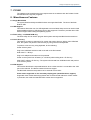
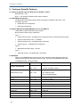
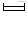
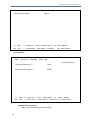
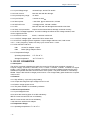
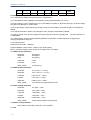
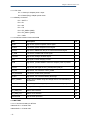
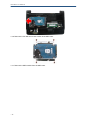
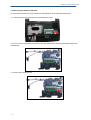
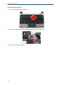
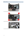
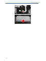
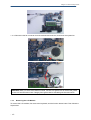
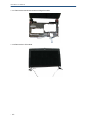
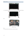
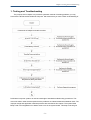
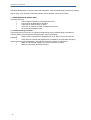
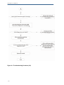
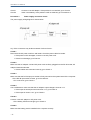
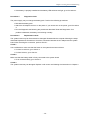
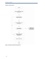
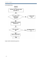
1
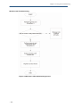
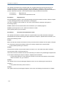
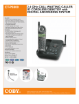
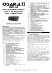
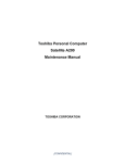
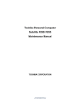
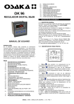
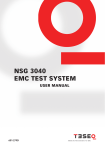
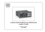
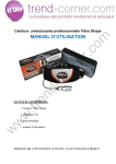
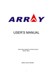
Chapter 1 System Description Specification Chapter1 System Description Specification 1. SCOPE This document describes the functional specifications for the Compal Netbook personal computer NTV00 series. The system is hardware and software compatible with the IBM PN/ATX personal computer. 1.1 CPU • Intel® Atom™ Processor N455 / N475 1.2 Memory • No on board memory • Support DDR-III 667MHz • One SODIMM Support with 1GB modules (Maximum Support 2GB) 1.3 Chipset • Intel® NM10 Express Chipset 1.4 Display • Support 10.1” WSVGA, 1024 x 600 1.5 Keyboard • 84/85 keys support with 100/101 key emulation without stick-point • Windows key, Application key • 17mm pitch, 2.0mm travel length • Multi-Language support 1.6 Hard Disk Drive (HDD) • 9.5mm, 2.5" S-ATA HDD, 5400rpm,160/250/320/500 GB capacity • 7200rpm, 160 GB capacity • Easily removable 1.7 Graphics Chip • Pineview-M (Intel® Graphics Media Accelerator 3150) 1.8 Audio • Realtek ALC272 • 2 channel HD Audio • Compliant with Universal Audio Architecture • Microphone-in and headphone-out • Two stereo 1.0W speakers 1.9 Pointing Device • Touchpad without buttons (support multi-touch) 1.10 I/O Ports -2- • RJ-45 jack x 1 • Headphone-out x 1 • Microphone-in x 1 • 3-in-1 Card Reader x1 • USB 2.0 x 3 NTV00 Service Manual • RGB: VGA port x 1, 15pins • DC-in jack x 1 • Kensington lock x 1 • Internal analog microphone x 1 1.11 System Status Indicators (UI spec) • 1 LED for Power Button(Blue) • 1 LED for Power Status(Blue) • 1 LED for Battery status (Charging / Full / L1 / L2) (Blue/Amber) • 1 LED for HDD activity (Blue) • 1 LED for Wireless LAN/Bluetooth (Blue) • 1 LED for T/P Disable (Amber) 1.12 Web Camera • 1.3M Pixel CMOS via USB2.0 interface 1.13 LAN • Realtek RTL8103EL 1.14 WLAN (Option) • Wireless LAN, 802.11b/g, 802.11n via PCI-E interface 1.15 3G • 3G module via USB2.0 interface 1.16 Bluetooth (Option) • Bluetooth Ver. 2.1 module with USB2.0 interface 1.17 Media Card Reader • 3-in-1 Card Reader(SD, MMC, MS) 1.18 Control Buttons • Power button x 1 • Magnetic lid switch control for system standby/resume 1.19 Kill Switch • YES, for WLAN/3G/Bluetooth 1.20 AC Adapter • Universal AC adapter. 100-240V AC, 50-60HZ, 0.8A ¾ 30W with 19V DC, 1.58A ¾ 2 pin 240V AC cable ¾ Wall-mount type 1.21 Battery • 3-cell Li-On, 18650 type, 2250mAh (Standard) • 6-cell Li-On, 18650 type, 4500mAh (Option) • Life Cycle: 70% Design Capacity after 300 Cycles in 25degreeC 1.22 Software • -3- Phoenix BIOS Chapter1 System Description Specification • Flash ROM 1MB • Support multi-boot • Suspend to RAM (S3)/Disk (S4) • Support SMBIOS 2.4 PCI2.2 • DMI utility for BIOS serial number configurable/asset tag • Support PXE • Wake on LAN from S3 • Wake on LAN from S4 in AC mode 1.23 Application • Wireless select enable/disable • Lock key 1.24 OS • Windows XP Home edition 32bit • Windows 7 1.25 Mini Card • 1 Mini-card slot for WLAN module 1.26 Security • Kensington lock 1.27 Regulatory -4- • EMI: FCC-B, CE, CCC, C-Tick, BSMI • Safety: Compliant to UL/CSA, TUV, CB, • WHQL LOGO (Windows XP home /Windows 7) • Energy Star 5.0 NTV00 Service Manual 2. Mechanical Specification FOR 10.1" Notebook 10.3"(W)x7.4"(D)x1.04"(H)[260.0mm(W)x186mm(D)x26.4mm(H)] 2.3lb~2.4lb(including: HDD and BATT module) 2.1 Option Pack: • AC adapter : 180g • HDD Pack : 104g(9.5mm) • SSD Pack : 14g • BATT (Li-ion) : 165g(3cell) • BATT (Li-ion) : 355g(6cell) 2.2 Mechanical Function • Removable HDD. • Module (BATT ) • Battery changeable (Li-ion). • For security can use Kensington Lock. • Scissor type key board standard pitch 2.0 m/m travel length. 2.3 Mechanical Material • Plastic PC+ABS(LG, GN-5001RFA),(UNI, MB-1700), (UNI, MB-8800), (BAYER, FR3002). • -5- Plastic PC+ABS+Talc (LG, GN-5151RFA),(UNI, TMB-1615) Chapter1 System Description Specification Chapter 2 Software Specification -6- NTV00 Service Manual 1. System Components Summary Processor Core Logic System Memory Display HDD Video Chip Audio On-board Comms Keyboard Pointing Device I/O Ports User keys AC adapter Battery Software Operating System -2- - Intel Atom 45nm Standard Voltage: - N455:1.66GHz. 667MHz FSB, 512KB L2 catch. - Intel Atom 45nm Standard Voltage: - N475:1.83GHz. 667MHz FSB, 512KB L2 catch. - Intel® NM10 Express Chipset. - No on board memory - Support DDR-III 667MHz. - SODIMM with 1GB/2GB modules (Maximum Support 2GB) Easy upgrade from bottom side for one SODIMM. - 10.1" WSVGA(1024 x600) - 9.5mm, 2.5" S-ATA HDD, 5400rpm, 160/250/320 GB capacity - Easily removable - Pineview-M (Intel® Graphics Media Accelerator 3150) - Realtek ALC272 - 2 channel HD Audio - Compliant with Universal Audio Architecture - Microphone-in and headphone-out - Two stereo 1.0W speakers with chamber - Realtek RTL8103EL - Wireless LAN, 802.11b/g, 802.11n via PCI-E interface - 3G module via USB2.0 interface - 1.3M Pixel CMOS via USB2.0 interface - Bluetooth Ver. 2.1 module with USB2.0 interface - 84/85 keys support with 100/101 key emulation - Windows key, Application key - 17mm pitch, 2.0mm travel length - Multi-Language support. - Touch Pad without buttons (support multi-touch) - RJ-45 jack x 1 - Headphone-out x 1 - Microphone-in x 1 - 3-in-1 Card Reader x1 - USB 2.0 x 3 - RGB: VGA port x 1, 15pins - DC-in jack x 1 - Power Button. x 1 - Kill switch x 1 - Magnetic Lid Switch. x 1 - Universal AC adapter. 100-240V AC, 50-60HZ ¾ 30W with 19V DC ¾ 2 pin 240V AC cable ¾ Wall-mount type - 3-cell Li-On, 18650 type, 2250mAh (Standard) - 6-cell Li-On, 18650 type, 4500mAh (Option) - Life Cycle: 70% Design Capacity after 300 Cycles in 25degreeC - Phoenix BIOS - Flash ROM 1MB - Support multi-boot - Suspend to RAM (S3)/Disk (S4) - Support SMBIOS 2.4 ,PCI2.2. - DMI utility for BIOS serial number configurable/asset tag - Support PXE - Wake on LAN from S3 - Wake on LAN from S4 in AC mode - Windows XP Home edition 32bit - Windows 7 Chapter2 Software Specification Control Buttons -3- - Power button x 1 - Magnetic lid switch control for system standby/resume NTV00 Service Manual 2. System Controls 2.1 Buttons 2.1.1 Power Button The activity of the power button is as follows: • If system is Off/Hibernate: System will be turned on while Power switch is depressed • If system is in Standby state: System will resume while Power switch is depressed. • If system on with legacy mode: depress this button will turn off power. If system is running in ACPI OS, the power button acts as the sleep button, and let OS controls the policy of power button which is defined in Power Option under the OS. 2.1.2 Power Button Over-ride Holding down the Power Button for 4 seconds will cause an unconditional transfer to the off state without notifying the operating system. 2.1.3 Lid switch If the system is running under legacy mode: • Closing the lid will turn off LCD backlight. If the system is running under ACPI mode: • The operating system will determine what action to take when the lid is opened and closed. The function of lid switch will follow the OS setting in power management (Nothing, Standby or Hibernate). If nothing, the backlight must turn off when the lid is closed. 2.2 System status indicators Please refer to Keyboard BIOS specification. -4- Chapter2 Software Specification 3. Core BIOS Features 3.1 Multi Boot The netbook can support Multi-Boot for selecting the boot sequence of Hard Drive, Removable Devices, Network in Setup. 4. Thermal management Please refer to Keyboard BIOS specification. 5. Power Management for ACPI mode 5.1 Introduction The netbook supports ACPI. The system will dynamically switch to ACPI mode for configuration and power management when an ACPI OS is loaded. When ACPI is not loaded and enabled, the power management function will be disabled. 5.2 System Time-outs If the system is running in ACPI mode, system Time-outs is handled by the operating system. BIOS time-outs are disabled. System time-outs are set using the control panel power applet. 5.3 System Power Management The overall system can be in one of the system power states as described below: ACPI mode Power Management Mech. Off (G3) All devices in the system are turned off completely. Soft Off (G2/S5) OS initiated shutdown. All devices in the system are turned off completely. Working (G0/S0) Individual devices such as the CPU and hard disk may be power managed in this state. S3 Sleeping State CPU set power down VGA Suspend Audio Suspend Hard Disk Power Down S4 Sleeping State System Saves all system states and data onto disk prior to power off the whole system. 5.4 Device Power Management Under ACPI mode, the device specific power management supported by this netbook includes the CPU throttling, monitor power management and the hard disk. 5.4.1 CPU power management ACPI mode The operating system detects when the system is idle and places the CPU in one of the 3 CPU low power states (C1, C2 or C3) depending on how much latency it believes the system can afford. The C1 state is simply the CPU halt instruction. The C2 state is the CPU stop grant state. The C3 state is the CPU stops clock state. The CPU stays in this state until an interrupt occurs. 5.4.2 Hard Disk -5- NTV00 Service Manual The operating system uses the spin down timer of the hard drive to set time-outs. The BIOS time-out of the hard disk must be disabled in ACPI mode. The user can sets the hard disk spin down time-out in the control panel power applet. 5.4.3 Display Device The monitor can be turned off after a period of no activity based on the settings of the OS. 5.4.4 System Wake Up Sources The table below lists the wake up events for all low power states: Events S3 S4 S5 Process required Any key O X X X Power button O O O X LAN (On board) O O X O RTC O O X O Critical low battery O X X O Field ‘Process Required’ identifies that further process for the occurred events must be processed during wake up or resume procedure. Notes: *1: Hot keys are not wake up source of standby, suspend to RAM and Hibernate states. *2:Lan(On board) and RTC can wake up source of Suspend and Hibernate states with AC mode. 5.4.4.1 LAN LAN (On board) The function of waking up the system from standby (DC/AC)/hibernation (AC mode) is supported. 5.4.4.2 Real Time Clock Alarm The Real Time Clock alarm interrupt will wake the system from Standby (DC/AC) / Hibernation (AC mode) 5.4.4.3 Critical Low Battery Critical low battery event can wake the system from Standby (DC mode) in ACPI mode. 5.5 Hibernation To support the hibernate state, the save to disk partition or file will be created by the operating system if the user select to enable the hibernation. It is the responsibility of the operating system to save the system state to a disk file and restore the system state when it is turned back on. -6- Chapter2 Software Specification 6. ACPI (Advanced Configuration and Power Interface) 6.1 Introduction The Advanced Configuration and Power Interface (ACPI) is a well-specified power management and configuration mechanism. It evolves the existing collection of power management codes, APM, PnP BIOS, and Etc. 6.2 ACPI Sleep Status BIOS must support the following sleep states – S3, S4 and S5. 6.3 Power State Transition Diagram The state transition diagram in ACPI mode is as follows: From (State) Leave By Condition Enter (State) S3 Power Button S0 On board LAN Any key Alarm Critical low battery(Only in DC mode) S4 Power Button S0 On board LAN (Only in AC mode) RTC(Only in AC mode) S5 Power Button S0 S0 Press Lid switch (depends on ACPI OS setting) S3 Standby icon in shutdown menu in Windows. ACPI OS timer expired Critical low battery (depends on ACPI OS setting) S0 Press Lid switch (depends on ACPI OS setting) S4 Press Power Button (depends on ACPI OS setting) S0 Press Lid switch (depends on ACPI OS setting) S5 Press Power Button (depends on ACPI OS setting) 6.4 Storage Devices and Batteries Possible storage devices are FDD, HDD, CD-ROM and DVD-ROM • Floppy Disk and Hard Disk, CD-ROM and DVD-ROM The BIOS must report the correct types of these devices if the drive is installed in the system during POST. Two devices, which belong to the same category, are not supported in this netbook. • -7- Batteries NTV00 Service Manual The BIOS must follow ACPI specification and report the correct number of the installed battery and status. 6.5 Bootable Device The system is capable of booting from onboard HDD, external USB Floppy and USB Flash device. 6.6 Embedded controller The keyboard controller will act as the ACPI embedded controller and support the ACPI EC protocol and interface. -8- Chapter2 Software Specification 7. PC2001 The netbook must meet Microsoft Logo requirements in accordance with the PC2001 Guide and the Microsoft Logo test programs. 8. Miscellaneous Features 8.1 Single BIOS ROM The system BIOS and Keyboard BIOS share one single flash ROM. The size of the flash ROM is 1MB. 8.2 USB Support This feature allows the use of a USB keyboard to access BIOS Setup and to be used in DOS without additional drivers. USB floppy boot is also supported. The driver provides other USB devices support after loading the operating system. 8.3 Flash utility – one BIOS ROM only The flash utility can be used to program both system and keyboard BIOS at the same time. 8.4 Crisis Recovery This feature provides an opportunity for system that cannot boot up. With a crisis USB flash stick, the system can perform crisis recovery by using internal PS2 keyboard. To perform crisis recovery using keyboard, do the following: Power off the system. Plug-in the USB flash stick drive with crisis with crisis file inserted. Hold down Fn + B keys. Plug-in AC adapter and make sure it is powered. Power on the system from off state (i.e. cold boot) while holding down <Fn+B> key. After POST, release <Fn+B> key. The system should read from USB flash stick and perform crisis recovery action. 8.5 VGA Support This section describes the expected behavior when a video monitor is connected to the VGA port on the netbook .The feature needs VGA driver support The BIOS will determine the presence of an external VGA monitor. Video modes supported on the secondary display path (need VGA driver support) Supported video modes and timings please refer to the technical reference of VGA vendor. In particular, text mode and standard VGA modes are not supported. -9- NTV00 Service Manual 9. Customer Specific Features 9.1 Display of System Type and BIOS Version Number on Boot BIOS Version V1.00* Note: * The numbers of BIOS version will be changed. 9.2 CMOS RAM management The BIOS will automatically update certain information in CMOS on each boot. This information includes: • DRAM size and configuration • Hard disk configuration 9.3 System Management BIOS(SM BIOS) version 2.4 (DMI 2.0) Limited DMI 2.0 BIOS information are provided: BIOS version number is type 0 data item. Type 1: • System serial number – 64 alphanumeric characters with 12-character bundle number • System manufacturer name – ‘COMPAL’ • System product name – 32 alphanumeric characters • System version – 32 alphanumeric characters Type 2: • Motherboard Product name – NTV00 Type 3: • Asset tag number –64 alphanumeric characters 9.4 EEPROM There is one EEPROM that is used to store many important system and user data in the netbook (some data are reserved for future to use). The size of the EEPROM is 2K bytes. The EEPROM map is listing as below: Name System Serial Number Offset Comments 00h – 1Fh 32 bytes of Serial number. 20h – 3Fh 32 bytes of Bundle number. 16 bytes for DMI Manufacturer name 40h – 4Fh type 0 BIOS Vendor type 1/2/3 Manufacturer System version 50h – 6Fh 32 bytes of System version. UUID 70h – 7Fh 16 bytes for UUID. System product name 80h – 9Fh 32 bytes of System product name. DMI type 11 A0h – DFh 64 bytes for DMI type 11 Reserved DEh – E9h Reserved AHCI EAh 1 bytes for AHCI Reserved EBh – EFh Reserved BIOS record data address E0h – FFh 32 bytes for BIOS record data address BIOS record data address FEh 1 bytes for BIOS record data address - 10 - Chapter2 Software Specification Reserved FFh Reserved LAN_FIRST_BOOT 100h 1 byte for LAN_FIRST_BOOT Reserved 101h – 1F2h Reserved BIOS record data address 100h-120h 32 bytes for BIOS record data address Reserved 121h – 1FFh Reserved Asset tag number 200h – 23Fh 64 bytes for DMI Type 3 Reserved 240h - 5FFh Reserved Factory record data address 600h – 6FFh 256 byte Factory record data address Reserved 700h - 7FFh Reserved - 11 - NTV00 Service Manual 10. System Setup 10.1 Invoking setup The setup function can only be invoked by pressing F2 when “Press <F2> to enter Setup” message is prompted on the bottom of screen during POST. During setup, all Fn function keys and power saving functions are disabled. 10.2 Setup screens 10.2.1 Main Menu Phoenix SecureCore(tm) Setup Utility Main Advanced Security Boot Exit Item Help System Time [12:00:00] System Date [01/01/2008] Product Name: XXXXXXX Serial Number XXXXXXX Total Memory XXX MB BIOS Version: VX.XX UUID Number: XXXXXXXXXXXXXXXX XXXXXXXXXXXXXXXX F1 Help Esc Exit ↑↓ Select Item ←→ Select Menu F5/F6 Change Values F9 Enter Select 4 Sub-Menu Setup Defaults F10 Save and Exit System Time and Date The hour is displayed with 24 hours format. The values set in these two fields take effect immediately. Product Name, Serial Number and UUID Number Display product name, serial number and UUID number. Total Memory This field reports the memory size of the extended memory with an integer in the system. BIOS Version This field displays current version of the BIOS. 10.2.2 Advanced Menu Phoenix SecureCore(tm) Setup Utility Main - 12 - Advanced Security Boot Exit specific Chapter2 Software Specification Item specific Help SATA Controller Mode: F1 ↑↓ Select Item Help Esc [AHCI] F5/F6 Change Values ←→ Select Menu Exit F9 Enter Select 4 Sub-Menu Setup Defaults F10 Save and Exit Security Menu Phoenix SecureCore(tm) Setup Utility Main Advanced Security Boot Exit Item specific Help Supervisor Password Is: Clear Set Supervisor Password: [Enter] F1 Help ↑↓ select item Esc Exit ←→ select menu F5/F6 change values Enter Select 4 Sub-Menu Set Supervisor Password Enter - 13 - F9 this field always shows the message. Setup defaults F10 Save and Exit NTV00 Service Manual While this field is highlighted, then press “Enter” the following message is shown: Set Supervisor Password Enter New Password [ Confirm New Password ] [ ] If there is an old password then setup will prompt with the following window instead and a current password will be required to be entered at first: Set Supervisor Password Enter current password [ Enter New Password Confirm New Password ] [ ] [ ] User can type password in field of enter new password”, and re-enter password in field of “confirm new password “ for verification. If verification OK: Setup Notice Changes have been saved. [Continue] The supervisor password is set complete after user press enter” If verification fail: Setup Warning Password does not match Re-enter Password [Continue] If password on boot is required, the password must be set otherwise it cannot be enabled. The formats of the password are as follows: Length Characters No more than 8 characters. Alphanumeric keys only. The shift status i.e. Ctrl, Shift, Alt, and Capital are ignored. 10.2.3 Boot Menu Phoenix SecureCore(tm) Setup Utility Main Advanced Security Boot Exit Item specific Help HDD1/SSD1 - 14 - Hark Disk Model name *1 Chapter2 Software Specification CD/DVD CD/DVD Drive Model name FDD LAN USB Memory *1 F1 Help ↑↓ Select Item Esc Exit ←→ Select Menu F5/F6 Change Values F9 Enter Select 4 Sub-Menu Setup Defaults F10 Save and Exit *1 : The menu will show up, if the device is available. This menu allows the user to decide the order of boot devices to load the operating system. Bootable devices include the diskette drive in module bay, the onboard hard disk drive and the CD-ROM in module bay. Exit Menu Phoenix SecureCore(tm) Setup Utility Main Advanced Security Boot Exit Item specific Help Exit Saving Changes Exit Discarding Changes Load Setup Defaults Discard Changes Save Changes F1 Help ↑↓ Select Item Esc Exit ←→ Select Menu F5/F6 Change Values F9 Enter Select 4 Sub-Menu Setup Defaults F10 Save and Exit Exit Saving Changes Allows the user to save changes to CMOS and reboot system. The following message is prompted when user press “Enter” on the item. - 15 - NTV00 Service Manual Setup Confirmation Save configuration changes and exit now? [Yes] [No] Yes: Exit SETUP and reboot No: Back to previous screen Exit Discarding Changes Setup Warning Configuration has not been saved! Save before exiting? [Yes] [No] Load Setup Defaults Allows the user loads default value in CMOS Setup. The following message is prompted when user press “Enter” on this item: Setup Confirmation Load default confirmation now? [Yes] [No] It still stay in Setup when press a key. Discard Changes Allows the user loads previous value in CMOS Setup. The following message is prompted when press “Enter” on this item: Setup Confirmation Load previous configuration now? [Yes] [No] It still stay in Setup when press a key. Save Changes Allows the user to save changes and not exit Setup. The following message is prompted when press “Enter” on this item: Setup Confirmation Save configuration changes now? [Yes] [No] It still stay in Setup when press a key. - 16 - Chapter2 Software Specification 11. OS Compatibility Netbook XP OS Compatibility : [Win7] Chapter 3 Hardware Chapter3 Hardware 1. Major Sub-assembly Specification System interconnection (For NTV00) 1.1 Top View NO Description CARD READER 2 SPEAKER Conn 3 Internal Mic Conn 4 LVDS 5 SIM Card Conn 6 Power Board Conn 7 K/B to MLB 8 T/P Module to MLB 9 Usb Board to MLB 0 21 -2- 3G Moudle B/T TO MLB NTV00 Service Manual 1.2 Bottom view NO Description NO Description 11 D-sub cable to MLB 20 FAN to MLB 12 Battery Conn 22 MINICARD_H15_STANDOFF 13 RJ45 23 THERMAL_H20_STANDOFF 14 USB Conn 15 Audio Jack (MIC for PINK) 16 Audio Jack (headphone for GREEN) 17 Mini PCI Express 18 DDRIII SOCKET 19 SATA HDD CONN -3- Chapter 4 DC-DC CONVERTER -1- Chapter4 DC-DC Converter 1. Power 3 cells Li-Ion 18650 size smart battery Pack with 24.975 Wh (3.7*2.25) capacity 6 cells Li-Ion 18650 size smart battery Pack with 49.95 Wh (3.7*4.5) capacity 2. DC-DC CONVERTER NTV00 Series Power System block diagram -2- NTV00 Service Manual 2.1. NTV00Adapter Description This specification defines the performance and characteristic of 30W AC adapter power supply. It supplies a constant voltage 19V output source for NTV00 series notebook computer. 2.2 Feature • Accepts universal input from 90V AC to 264V AC • Offers constant Voltage 19V output source with 30W max output power capacity. • High efficiency 85% min at 100~240Vac • Compact Size 2.3 Adapter Electrical Specification 2.3.1 Input Voltage range: universal input, 90VAC to 264VAC 2.3.2 Inrush current: less than 50A with No damage. 2.3.3 Input frequency range: 47~63Hz 2.3.4 Input Current: 0.8Amax at 100VAC 2.3.5 Start-up time: ≤ 5sec Max. @115 and 230 Vac, full load 2.3.6 HOLD-UP time: >10ms@115VAC, full load condition 2.3.7 OVP: less than 26V with No damage and automatic shut down 2.3.8 Short circuit protection: Output can be shorted without damage, and auto recovery 2.3.9 OUTPUT Voltage Regulation: 18.5-20V including the effects of line Voltage variation, load current, ripple and noise 2.3.10 OUTPUT Current: Current: 0Amin, 1.58Amax continuous 2.3.11 OUTPUT Voltage ripple: 250mv PK-PK for resistor load. 2.3.12 OUTPUT Voltage Dynamic regulation: Output voltage within18.5-20V, load current 10%←→100%, frequency 100Hz, 50% duty cycle, recover time ≤ 1msec. 2.3.13 DC OUTPUT PIN OUT: PIN1 Center Pin Adapter +output PIN2 Barrel (Ring) Adapter returns. 2.3.14 Temperature Range: Operating temperature: 0 °C TO 40 °C Storage temperature: -20 °C TO 65 °C 2.3.15 NTV00 Adapter Description This specification defines the performance and characteristic of 30W AC adapter power supply. It supplies a constant voltage 19V output source for NTV00series notebook computer. 2.3.16 Feature Accepts universal input from 90V AC to 264V AC Offers constant Voltage 19V output source with 30W max output power capacity. Meet EPA Energy Star level-5 requirement Compact Size 2.4 Electrical Specification -3- Chapter4 DC-DC Converter 2.4.1 Input Voltage range: universal input, 90VAC TO 264AC 2.4.2 Inrush current: less than 50A with No damage. 2.4.3 Input frequency range: 47~63Hz 2.4.4 Input Current: 1.0Amax at 100VAC 2.4.5 Start-up time: ≤ 5sec Max. @115 and 230 Vac, full load 2.4.6 HOLD-UP time: >10ms@115VAC, full load condition 2.4.7 OVP: less than 26V with No damage and automatic shut down 2.4.8 Short circuit protection: Output can be shorted without damage, and auto recovery 2.4.9 OUTPUT Voltage Regulation: 18.5-20V including the effects of line Voltage variation, load current, ripple and noise 2.4.10 OUTPUT Current: 0Amin, 1.58Amax continuous 2.4.11 OUTPUT Voltage ripple: 250mv PK-PK for resistor load 2.4.12 OUTPUT Voltage Dynamic regulation: Output voltage within18.5-20V, load current 10%←→100%, frequency 100Hz, 50% duty cycle, recover time ≤ 1msec. 2.4.13 DC OUTPUT PIN OUT: PIN1 Center Pin Adapter +output PIN2 Barrel (Ring) Adapter returns. 2.4.14 Temperature Range: Operating temperature: 0 °C TO 40 °C Storage temperature: -20 °C TO 65 °C 3. DC-DC CONVERTER 3.1 Description The DC-DC converter is designed to supply the power for NTV00 series notebook computer of Compal. It supply +5VALWP, +3VALWP, +1.8V, +1.5VSP, +1.05VSP, +0.9VSP, +0.89VSP, for logical system, +CPU_CORE for CPU and supplies +3VALWP for the built-in KB926 microprocessor which handles the keyboard and PMU control functions of the system. The power ON/OFF is controlled by KB926. There is also a built-in charger power source. It can charge battery pack whether the computer is ON or OFF. 3.2 Features 3.2.1 High efficiency, up to 85% (using battery) 3.2.2 Accept wide range DC input voltage from 9V to 19V 3.2.3 Built-in charger power source 3.2.4 The power ON/OFF is controlled by software 3.3 Electrical specification 3.3.1 Input Voltage/Current 9V to19V at the summing point of AC-DC and battery INPUT Current 3.375A max from 3-cell battery INPUT Current 6.75A max from 6-cell battery 1.58A max from 30W AC-DC Adapter. 3.4 Temperature Range: 3.4.1 Operating temperature: 0° C to 40° C -4- NTV00 Service Manual 3.4.2 Storage temperature range: -20° C to 65° CDC/DC OUTPUT 3.4.3 Fixed output voltage/Current Item +5VALWP +3VALWP +1.8VP Nominal voltage +5V +3.3V +1.8V Min. current 0A 0A 0A Max. Current 4.16A 4.32A 2.46A Peak current 5.94A 6.17A 3.52A Total regulation 5V±5% 3.3V±5% 1.8V±5% Ripple voltage 100mVp-p max. 66mVp-p max. 36mVp-p max Item +1.5VSP +0.89VSP + 1.05VSP Nominal voltage +1.5V +0.89V +1.05V Min. current 0A 0A 0A Max. Current 1.61A 1.85A 2.45A Peak current 2.30A 2.64A 3.50A Total regulation 1.5V±5% 0.89V±5% 1.05V±5% Ripple voltage 30mVp-p max. 18mVp-p max. 21mVp-p max. Item +0.9VSP +CPU_CORE Nominal voltage +0.9V +1.024~+1.25V Min. current 0A 0A Max. current 0.21A 4.23A Peak current 0.3A 6.04A Total regulation 0.9V±5% -5.8mv/A Ripple voltage 18mVp-p max 3.5 VOLTAGE IDENTIFICATION CODES -5- 20mVp-p max Chapter4 DC-DC Converter -6- VID6 VID5 VID4 VID3 VID2 VID1 VID0 VDAC 0 0 1 1 0 0 0 1.2000 0 0 1 1 0 0 1 1.1875 0 0 1 1 0 1 0 1.1750 0 0 1 1 0 1 1 1.1625 0 0 1 1 1 0 0 1.1500 0 0 1 1 1 0 1 1.1375 0 0 1 1 1 1 0 1.1250 0 0 1 1 1 1 1 1.1125 0 1 0 0 0 0 0 1.1000 0 1 0 0 0 0 1 1.0875 0 1 0 0 0 1 0 1.0750 0 1 0 0 0 1 1 1.0625 0 1 0 0 1 0 0 1.0500 0 1 0 0 1 0 1 1.0375 0 1 0 0 1 1 0 1.0250 0 1 0 0 1 1 1 1.0125 0 1 0 1 0 0 0 1.0000 0 1 0 1 0 0 1 0.9875 0 1 0 1 0 1 0 0.9750 0 1 0 1 0 1 1 0.9625 0 1 0 1 1 0 0 0.9500 0 1 0 1 1 0 1 0.9375 0 1 0 1 1 1 0 0.9250 0 1 0 1 1 1 1 0.9125 0 1 1 0 0 0 0 0.9000 0 1 1 0 0 0 1 0.8875 0 1 1 0 0 1 0 0.8750 0 1 1 0 0 1 1 0.8625 0 1 1 0 1 0 0 0.8500 0 1 1 0 1 0 1 0.8375 0 1 1 0 1 1 0 0.8250 0 1 1 0 1 1 1 0.8125 0 1 1 1 0 0 0 0.8000 0 1 1 1 0 0 1 0.7875 0 1 1 1 0 1 0 0.7750 0 1 1 1 0 1 1 0.7625 0 1 1 1 1 0 0 0.7500 0 1 1 1 1 0 1 0.7375 0 1 1 1 1 1 0 0.7250 NTV00 Service Manual 0 1 3.6 Charger 1 1 1 1 1 1 0.7125 0 0 0 0 0 0 0.7000 3.6.1 Controlled by KB926 microprocessor from motherboard 3.6.2 Temperature sense capability for the battery (charge active between 0°C~ 50°C) 3.6.3 Fast charge current 1.5Amps (max.) for Li-Ion Battery at system off, approach 28.5(19*1.5) W fast charge at system ON. (Depend on system load) 3.6.4 Trickle charge: Typical 500mA pre-charge current for Li-Ion Battery. All trickle charge are controlled by KB926. 3.6.5 Charge termination: When Fully-Charge bit is set, charger is terminated by KB926 3.6.6 When system turns off, the charged time from empty to full be 3 hrs typically and Li-ION battery. 3.5.0hrs maximum for 3.6.7 Other battery services are presented by KB926 microprocessor includes maximum charging timer, charging temperature range etc. 3.6.8 Charger power: Constant current mode: 1.58A±8% Constant adapter current mode: 1.58A±7% (For 30W system) BATT+ Constant Voltage mode: 12.6V±1% for 3cell/6 cell Li-Ion battery. 3.7 OVER Current protection: +5VALWP: +3VALWP: +1.8V: 6.37A(min.) 6.43A(min.) 6.37A(min.) +0.89VSP: 5.92A +1.05VSP: 6.01A +CPU_CORE: 10.169A (min.) 3.8 OVER Voltage protection: +5VALWP: 5V *(112.5% ~ 117.5%) +3VALWP: 3.3V *(112.5% ~ 117.5%) +1.05VSP: 1.05V*(110% ~ 120%) +1.8VSP: 1.8V*(110% ~ 120%) +0.89VSP: 0.89V*(110% ~ 120%) +CPU_CORE over 160mV of programmed VID level 3.9 Under voltage protection +5VALWP: 5V *(65% ~ 75%) +3VALWP: 3.3V *(65% ~ 75%) +1.05VSP: 1.05V*(65% ~ 75%) +1.8VSP: 1.8V*(65% ~ 75%) +0.89VSP: 0.89V*(65% ~ 75%) +CPU_CORE Under 230mV programmed VID level 3.10 Short circuit protection: Latch mode for+5VALWP,+3VALWP,,+CPU_COREP 3.11 I/O -7- Chapter4 DC-DC Converter 3.11.1 DC-Jack Pin 1: Center pin Adapter power +input Pin 2: Barrel (Ring) Adapter power return 3.11.2 Battery Connector Pin 1: BATT++ Pin 2: ID Pin 3: B/I Pin 4: TS Pin 5: EC_SMDA (SMD) Pin 6: EC_SMCA ((SMC) Pin 7: GND 3.11.3 Interface between Powers with M/B Item Description I/O SUSP High Active, system suspend control signal I SUSP# Low Active, system suspend control signal I SYSON High Active, KB926 use this pin to control the SYSON signal I 51_ON# Low Active, POWER ON control signal I FSTCHG High Active, Charger enables signal. I IREF A/D signal, Control charging current I ACIN High Active, provide KB926 to mean the Adaptor power is present O VGATE High Active, the signal is CPU_CORE power good pin O VR_ON High Active, turn on/off the +CPU_CORE I CLK_ENABLE# Low Active, enable clock generator O ACOFF High Active, turn on/off the Battery discharge I BATT_TEMPA Analog signal, KB926 using this voltage level to calculate battery’s temperature O VID [0..6] The +CPU_CORE voltage depends on those PINs VID[6..0] I CHGRTC Charge RTC-battery power source O EC_SMB_DA1 SMbus data interface I/O EC_SMB_CK1 SMbus clock interface I/O MAINPWON H/W Thermal protection O 3.12 BATTERY 3.12.1 Li-ion Smart battery for NTV00 18650 3S1P 11.1V/2250 mAH 18650 3S2P 11.1V/4500 mAH -8- NTV00 Service Manual More than 300 charging/discharging cycles. Modularized battery pack, easy to be replaced. 3.12.2 Battery Specification 1-1. EE information Battery Design Capacity(mAH) Battery Configuration Battery Nominal Voltage(V) Single Cell Chemistry Single Cell Type Single Cell Capacity(mAH) Dumb/Smart Battery Cycle Life Nominal Charging Voltage(V) Nominal Charging Current(A) Protection Function 3 cell 6 cell 2250 4500 3S1P 3S2P 11.1 11.1 Li-ion 18650 Li-ion 18650 2250 2250 Smart Battery (SMBus ver. 1.1.) 300cycle 70% Smart Battery (SMBus ver. 1.1.) 300cycle 70% 12.6 12.6 1.575 3.150 OVP UVP OTP OCP OVP UVP OTP OCP Battery Design Capacity(mAH) Battery Configuration Battery Nominal Voltage(V) Single Cell Chemistry Single Cell Type Single Cell Capacity(mAH) Dumb/Smart Battery Cycle Life Nominal Charging Voltage(V) Nominal Charging Current(A) Protection Function 1-2. Battery Connector Pin Assignment Connector Male on M/B: ALLTOP-C144U2 Connector Female on Battery: ALLTOP-C144U1 Pin No. Symbol Comments 7 GND Battery Negative Terminal. 6 SMC SMBus clock interface I/O pin. 5 SMD SMBus data interface I/O pin. 4 TS Connect to thermister(Note 3) 3 B/I Battery-In Pin(Note 2) 2 ID Identify pin(Note 1) 1 BATT+ Batt+, Battery Positive Terminal. Note: 1. ID pin must be floating. 2.The battery can be charged/discharged only while this pin is connected to GND by the system. 3.Thermister: DTN-C103F3H-SYS115A (or 103AT2 equivalent). The other thermister Pin is connected GND. -9- Chapter4 DC-DC Converter 3.12.3 2.6.12.2 On board RTC battery: Maxell ML1220T13RE /3.0V /14mAH Lithium. 3.12.4 2.6.12.3 Sanyo ML1220T28 /3.0V /15mAH Lithium 4. Safety Protection 4.1 Open lamp protection: When inverter is on open lamp status, any component on inverter should be O.K and inverter is no damaged, no fire and no arcing. If inverter can’t shunt down during open lamp happen, inverter must pass below conditions: i.) Human body test. ii.) Open lamp burning: Inverter burns for 24 hours at open lamp status. No parts damage. 4.2 Human body safety test: Short inverter output, transformer secondary output to GND by a 2KΩ resistor which connects one end to GND and another one to those outputs. They should meet output current limitation requirement as follow. Output current I is the current that flows through 2KΩ resistor. 1. Output current I ≦ 0.7mA , if frequency f ≦ 1KHz 2. Output current I ≦ 0.7mA * f (kHz), if f ≧ 1KHz. However, output current should be less than 70mA even frequency is more than 100KHz. 4.3 Abnormal test: Any one component is short or open; inverter should be no fire, no arcing. And result must meet output current limitation requirement. - 10 - Chapter 5 Disassembly Guide -1- 1. Disassembling the Base Unit These are the directions for disassembling the base unit. You will need a 5.5mm Nut Driver, a medium size Philips screwdriver. These directions are to disassemble the complete unit and are cross-referenced to Chapter 7 for the replacement of component parts. Before disassembly, make sure the notebook is powered off. 1.1 Removing the Battery Module To remove the battery pack from the battery bay, follow the steps below: 1.1.1 Turn the notebook upside down. 1.1.2 Slide the battery lock to unlock the battery pack. 1.1.3 Slide the battery release latch in the direction of the arrow; gently pry the battery pack from its housing. NOTE: Always start laptop disassembly by removing the battery pack first. -2- Chapter 5 Disassembly Guide 1.2 Removing the HDD Module Follow the steps below to remove the HDD module: 1.2.1 Turn the notebook upside down. 1.2.2 Remove the 3 M2.0x3 screws securing the bottom cover. 1.2.3 Pull up the bottom cover in the direction of the arrow. 1.2.4 Remove the two M2.0x3 screws securing the HDD module in place. 1.2.5 Pull the tab to remove the HDD module in the direction of the arrow. -3- NTV00 Service Manual 1.2.6 Remove the four M2.0x3 screws to take off the HDD case. 1.2.7 Remove the HDD module from the HDD case. -4- Chapter 5 Disassembly Guide 1.3 Removing the RAM Module Follow the steps below to remove the HDD module: 1.3.1 Push the latches of the RAM socket. The module will be released and pop up. 1.3.2 Grasp the module and pull it out. -5- NTV00 Service Manual 1.4 Removing Bluetooth Card To remove the Bluetooth card, firstly remove the HDD door, then follow the steps below: 1.4.1 Remove the 1 M2.0x3 screw as shown: 1.4.2 lift out the Bluetooth card: -6- Chapter 5 Disassembly Guide 1.5 Removing the Wireless LAN Card To remove the wireless LAN card, first remove the HDD door. Then follow the steps below: 1.5.1 Disconnect the two antennas from the Wireless Lan card. 1.5.2 Turn over the motherboard and remove the two M2x3 screws securing the wireless card to the motherboard. 1.5.3 Remove the wireless card. -7- NTV00 Service Manual 1.6 Removing the Keyboard 1.6.1 Lift up the keyboard from bottom side. 1.6.2 Pull the keyboard towards you, revealing the keyboard cable underneath. 1.6.3 Lift and remove the keyboard. -8- Chapter 5 Disassembly Guide 1.7 Removing the Logic Upper To remove the logic upper, first remove the battery pack, HDD, RAM, keyboard, wireless LAN card. Follow the steps below to remove the logic upper. 1.7.1 Turn the notebook upside down and remove the 8 M2.0x5 screws from the bottom side of the notebook. 1.7.2 Remove the 5 M2.0x3 screws from the lower side as shown. 1.7.3 Turn the notebook over and remove the 2 M2.0x5 screw attaching the logic upper to the motherboard. 1.7.4 Disconnect the MIC and fingerprint cables as shown. -9- NTV00 Service Manual 1.7.5 Lift off the logic upper.(detail information please refer to the reference) 1.7.6 Remove power board, loose two M2.0x5 screw to release the power board. 1.7.7 Remove TP module. - 10 - Chapter 5 Disassembly Guide - 11 - NTV00 Service Manual 1.8 Removing the USB Board To remove the USB board, first remove the logic upper. Then follow the steps below: 1.8.1 Release the USB FFC as shown: 1.8.2 Loose two M2.0x3 screw & remove the USB board as shown: 1.9 Removing the Speaker To remove the speaker, first remove the logic upper. Then follow the steps below: - 12 - Chapter 5 Disassembly Guide 1.9.1 Lift out the speaker & loose screw as shown. 1.10 Removing the Motherboard To remove the motherboard, first remove the logic upper. Then follow the steps below: - 13 - NTV00 Service Manual 1.10.1 Disconnect the antennas, daughters and LVDS cable as shown below: 1.10.2 Lift out the motherboard. 1.11 Removing Thermal module To remove the thermal module, first remove the MB(with thermal and memory. Then follow the steps below: 1.11.1 Remove the 4 M2.0x3 screw on MB ASSY. - 14 - Chapter 5 Disassembly Guide 1.11.2 Disconnect the fan connector from the motherboard as shown, and lift out the system fan. CAUTION: When you remove the thermal module, use the CPU grease tool to remove the grease on the CPU and thermal module. Reapply fresh grease before reinstalling the thermal module. 1.12 Removing the LCD Module To remove the LCD module, first remove the keyboard, and the function button board. Then follow the steps below: - 15 - NTV00 Service Manual 1.12.1 Remove the two M2.0x5 screws on hinge front side. 1.12.2 Remove the LCD module. - 16 - Chapter 5 Disassembly Guide 1.13 Disassembling the Display To disassemble the display and inverter board, first remove the LCD module. Then follow these steps: 1.13.1 Remove the four screw pads . 1.13.2 Remove the 4 M2.0x4 screws securing the LCD bezel to the LCD module. 1.13.3 Carefully insert your fingers between the display and the LCD bezel as indicated by the arrow, and gently pry up the LCD bezel.(detail information please refer to the reference) 1.13.4 Remove the 2 M2.0X3 screws mounting the display, - 17 - NTV00 Service Manual 1.13.5 Gently lift out the display. Remove the four M2x3 screws securing the hinges to the display. Panel Cover 1.13.6 Disconnect the inverter cable from the back of the LCD panel. - 18 - Chapter 5 Disassembly Guide - 19 - NTV00 Service Manual 1.14 Removing the Camera Module To remove the camera module, first remove the LCD module and lift out LCD display and inverter board. Then follow these steps: 1.14.1 Remove the camera module. - 20 - Chapter6 Testing and Troubleshooting -1- Chapter 6 testing and troubleshooting 1. Testing and Troubleshooting The purpose of this chapter is to provide a systematic method of isolating problems you may have with the NTV00 series Notebook Computer. We assume that you have a basic understanding of DOS-based computer systems as well as knowledge of standard troubleshooting procedures. This manual is written under the assumption that the problems are indeed related with Notebook itself. The improper usage and application software problems are excluded in this chapter. The system BIOS Beep Code is an integrated unit to detect some errors in the system board. This beep code will give -2- NTV00 Service Manual immediate identification of certain system board problems. If the troubleshooting procedure is followed step by step, it can efficiently isolate the problem and the problem can be solved easily. 1.1 PERFORM VISUAL INSPECTION Check the following: • Power cords are properly connected and secured • Power supply is adequate for operation • There are no obvious shorts or opens • There are no obviously burned or heated components • All components appear normal 1.2 Troubleshooting Flowchart Use the flowchart in Figure 6-1 as a guide for determining which troubleshooting procedures to execute. Before going through the flowchart steps, verify the following: • Ask the user if a password is registered and, if it is, ask him or her to enter the password. • Verify with the customer that windows XP is installed on the hard disk. Operating systems that were not preinstalled by Compal can cause the computer to malfunction. • Make sure all optional equipment is removed from the computer. • Make sure the floppy disk drive is empty. -3- Chapter 6 testing and troubleshooting Figure 6-1 Troubleshooting flowchart (1/2) -4- NTV00 Service Manual Figure 6-1 Troubleshooting flowchart (2/2) -5- Chapter 6 testing and troubleshooting If the diagnostics program cannot detect an error, the problem may be intermittent. The test program should be executed several times to isolate the problem. When a problem has been located, perform the appropriate troubleshooting procedures as follows: If an error is detected by the main battery test, perform the Power Supply Troubleshooting procedures in Section 6-2. If an error is detected by the display test, perform the Display Troubleshooting procedures in Section 6-3. If an error is detected by the keyboard test, perform the Keyboard Troubleshooting procedures in Section 6-4. If an error is detected when using an external USB device, perform the External USB Devices Troubleshooting procedures in Section 6-5. If an error is detected when using the CRT connection, perform the CRT Failure Troubleshooting procedures in Section 6-6. If an error is detected when using the touch pad, perform the Touch Pad Troubleshooting procedures in Section 6-7. If an error is detected when using the speakers, perform the Speaker Troubleshooting procedures in Section 6-8. If an error is detected when using the Wireless LAN unit, perform the Wireless LAN Troubleshooting procedures in Section 6-9. -6- NTV00 Service Manual Power Supply Troubleshooting Figure 6-2 Power Supply Troubleshooting Process -7- Chapter 6 testing and troubleshooting The power supply controls many functions and components. To determine if the power supply is functioning properly, start with Procedure 1 and continue with the other Procedures as instructed. The flowchart in Figure 6-2 gives a summary of the process. The procedures described in this section are: Procedure 1: Power status check Procedure 2: Adaptor / battery replacement Procedure 3: Power supply connection check Procedure 4: Diagnostic check Procedure 5: Internal connection check Procedure 1 Power Status Check The following LEDs indicate the power supply status: Battery LED The power supply controller displays the power supply status through the Battery and the POWER LEDs as listed in the tables below. Table 2-1 Battery LED Battery State Charging LED colors blue, blinking blue, solid on color off Discharging Amber, blinking LED on for 1 second every 4 seconds Amber, blinking (LED on 1 second every 2 seconds) Color off Definition Battery charging with AC Battery fully charged by AC Battery abnormal: stop charging with AC (Bad cell/ Overheated) Battery within low state: 12 minutes remaining Battery within critical low state: 3 minutes remaining. The system is protected and cannot be re-powered on without the AC power connected. Battery not in low or critical low state; in discharging state Table 2-2 POWER LED Power supply status System Power On (LED is solid blue). System Suspended POWER LED blue Solid on Blue blinking System Power Off. Off To check the power supply status, install a battery pack and connect an AC adaptor to the DC-IN port on the computer and to a power supply. If the Battery LED is not lit, go to Procedure 2 Procedure 2 Adaptor / battery replacement A faulty adaptor may not supply power or may not charge the battery. Perform Check 1. -8- NTV00 Service Manual Check 1 Connect a new AC adaptor. If the problem is not resolved, go to Check 2. Check 2 Insert a new battery. If the problem is still not resolved, go to Procedure 3. Procedure 3 Power supply connection check The power supply wiring diagram is shown below: Any of the connectors may be disconnected. Perform Check 1. Check 1 Disconnect the AC power cord from wall outlet. Check the power cable for breaks. If the power cord is damaged, connect a new AC power cord. If there is no damage, go to Check 2. Check 2 Make sure the AC adaptor cord and AC power cord are firmly plugged into the DC-IN socket, AC adaptor inlet and wall outlet. If these cables are connected correctly, go to Check 3. Check 3 Make sure that the DC-IN input port socket is firmly secured to the system board of the computer. If the DC-IN input socket is loose, go to Procedure 5. If it is not loose, go to Check 4. Check 4 Use a millimeter to make sure that the AC adaptor output voltage is close to 19 V. If the output is several percent lower than 19 V, go to Check 5. If the output is close to 19 V, go to Check 6. Check 5 Connect a new AC adaptor or AC power cord. If the battery LED does not light, go to Check 6. Check 6 Make sure the battery pack is installed in the computer correctly. -9- Chapter 6 testing and troubleshooting If the battery is properly installed and the battery LED still does not light, go to Procedure 4. Procedure 4 Diagnostic check The power supply may not charge the battery pack. Perform the following procedures: Reinstall the battery pack. Attach the AC adaptor and turn on the power. If you cannot turn on the power, go to Procedure 5. Run the Diagnostic test following the procedures described Tests and Diagnostics. If no problem is detected, the battery is functioning normally. Procedure 5 Replacement check The system board may be disconnected or damaged. Disassemble the computer following the steps described Replacement Procedures. Check the connection between the AC adaptor and the system board. After checking the connection, perform Check 1: Check 1 Use a millimeter to make sure that the fuses on the system board are not blown. If a fuse is not blown, go to Check 2. If a fuse is blown, go to Check 3. Check 2 Make sure that the battery cable is firmly connected to the system board. If it is connected firmly, go to Check 3. Check 3 The system board may be damaged. Replace it with a new one following the instructions in Chapter 4. - 10 - NTV00 Service Manual Display Troubleshooting Figure 6-3 Display troubleshooting process - 11 - Chapter 6 testing and troubleshooting This section describes how to determine if the computer’s display is functioning properly. The process is outlined in Figure 6-3. Start with Procedure 1 and continue with the other procedures as instructed. Procedure 1: External display check Procedure 2: Diagnostic check Procedure 3: Connector and replacement check Procedure 1 External display check Connect an external display to the computer’s external monitor port, then boot the computer. The computer automatically detects the external display. Press Fn+F3 to switch to the external display. If the external display works correctly, the internal LCD may be damaged. Go to Procedure 3. If the external monitor appears to have the same problem as the internal monitor, the system board may be damaged. Go to Procedure 2. Procedure 2 Diagnostic check The Display Test program is stored on the computer’s Diagnostics disk. This program checks the display controller on the system board. Insert the Diagnostics disk in the computer’s floppy disk drive, turn on the computer and run the test. Refer to Chapter 3, Tests and Diagnostics for details. If an error is detected, go to Procedure 3. If an error is not detected, the display is functioning properly. Procedure 3 Connector and replacement check The FL inverter board, LCD module, and system board are connected to the display circuits. Any of these components may be damaged. Replacement Procedures, for instructions on how to disassemble the computer and then perform the following checks: Check 1 Make sure the DDRRAM module is seated properly. Test display again. If the problem still exits, replace the DDRRAM module. If the problem still exists, perform check 2. Check 2 Replace the FL inverter board with a new one and test display again. If the problem still exists, perform Check 3. Check 3 Replace the LCD module with a new one and test display again. If the problem still exists, perform Check 4. Check 4 Replace the LCD/FL cable with a new one and test display again. If the problem still exists, perform Check 5. Check 5 Replace the CPU with another of the same specifications. If the problem still exists, perform Check 6. Check 6 The system board may be damaged. Replace it with a new one. - 12 - NTV00 Service Manual Keyboard Troubleshooting Figure 6-4 Keyboard troubleshooting process - 13 - Chapter 6 testing and troubleshooting To determine if the computer’s keyboard is functioning properly, perform the following procedures. Figure 6-5 outlines the process. Start with Procedure 1 and continue with the other procedures as instructed. Procedure 1: External keyboard check Procedure 2: Diagnostic check Procedure 3: Connector and replacement check Procedure 1 External keyboard check Connect a USB keyboard to one of the computer’s keyboard/mouse ports, then boot the computer. The computer automatically detects the external keyboard. If the external keyboard works correctly, the internal keyboard or its connections may be faulty. Go to Procedure 2. If the external keyboard appears to have the same problem as the internal keyboard, the system board may be damaged. Procedure 2 Diagnostic test Run the Diagnostic Program, which will automatically execute the Keyboard Test. Refer to Chapter 3, Tests and Diagnostics for more information on how to run the program. If an error is located, go to Procedure 3. If an error does not occur, the keyboard is functioning properly. Procedure 3 Connector and replacement check The keyboard and/or system board may be disconnected or damaged. Replacement Procedures and perform the following checks. Check 1 Make sure the keyboard cable is firmly connected to the system board. If the connection is loose, reconnect firmly and repeat Procedure 2. If there is still an error, go to Check 2. Check 2 The keyboard may be damaged. If the problem still exists, perform Check 3. Check 3 The system board may be damaged. Replace it with a new one. - 14 - NTV00 Service Manual External USB Devices Troubleshooting Figure 6-5 External USB device troubleshooting process - 15 - Chapter 6 testing and troubleshooting To determine if the computer’s external USB devices are functioning properly, perform the following procedures. Figure 6-5 outlines the process. Start with Procedure 1 and continue as instructed. Procedure 1: External device and connection check Procedure 2: Replace system board Procedure 1 External device and connection check The USB device may be damaged or the connection may be faulty. Perform Check 1. Check 1 Make sure USB device cable is firmly plugged into one of the USB sockets. If the cable is connected correctly, go to Check 2. Check 2 Plug the USB device into another USB socket (there are three in all). If the USB device still does not work, go to Check 4. If the device functions correctly when connected to another USB port, go to Check 3 Check 3 Make sure that the USB socket is firmly secured to the system board of the computer. If the malfunction remains, the system board may be damaged. Go to Procedure 2. Check 4 Connect an alternative USB device to one of the computer’s USB ports, and then boot the computer. The computer automatically detects the external device. If the alternative USB device works correctly, the original device may be damaged and should be replaced. If the alternative USB device appears to have the same problem as the original device, the system board may be damaged. Go to Procedure 2. Procedure 2 Replace system board If the error persists, the system board may be damaged. - 16 - NTV00 Service Manual CRT troubleshooting Figure 6-6 CRT troubleshooting process - 17 - Chapter 6 testing and troubleshooting To determine if the computer’s CRT port is functioning properly, perform the following procedures. Figure 6-6 outlines the process. Start with Procedure 1 and continue as instructed. Procedure 1: CRT connection check Procedure 2: CRT set check Procedure 1 CRT connection check The CRT cable may be damaged or the connections may be loose. Perform Check 1: Check 1 Make sure CRT cable is firmly plugged into both the CRT set and the CRT port of the computer. If the cable is connected correctly, go to Check 2. Check 2 Make sure the CRT port is firmly secured to the system board of the computer. If the malfunction remains, go to Check 3. Check 3 The CRT cable may be damaged. Replace with a good cable. If the malfunction remains, go to Procedure 2 Procedure 2 CRT set check The CRT set may be faulty. Perform Check 1 Check 1 Try using the set for CRT reception. If it does not work, the set may be damaged. If the set does work, perform Check 2. Check 2 Try connecting a different CRT to the computer. If the replacement television works, the original set may be damaged. If the replacement set does not work the system board may be damaged - 18 - NTV00 Service Manual Touch Pad Troubleshooting Figure 6-7 Touch Pad troubleshooting process - 19 - Chapter 6 testing and troubleshooting To determine if the computer’s built-in Touch Pad is functioning properly, perform the following procedures. Figure 6-7 outlines the process. Start with Procedure 1 and continue as instructed. Procedure 1: Touch Pad connection check Procedure 2: Touch Pad replacement check Procedure 1 Touch Pad connection check The Touch Pad is connected by the Touch Pad FPC to the system board. Make sure the Touch Pad FPC cable is firmly connected to the Touch Pad and system board. Replacement Procedures for instructions on how to disassemble the computer and then perform the following checks. If any of the connections are loose, reconnect firmly. If any of the connections is damaged, or there is still an error, go to Procedure 2. Procedure 2 Touch Pad replacement check The Touch Pad unit or FPC may be defective or damaged. - 20 - NTV00 Service Manual Speaker Troubleshooting Figure 6-8 Speaker troubleshooting process - 21 - Chapter 6 testing and troubleshooting To determine if the computer’s built-in speakers are functioning properly, perform the following procedures. Figure 6-8 outlines the process. First adjust the speaker volume to an appropriate level. Start with Procedure 1 and continue as instructed. Procedure 1: Audio source test Procedure 2: Earphone test Procedure 3: Connection check Procedure 4: Replacement check Procedure 1 Audio source test Try different audio sources (e.g. an audio CD and digital music file) to determine whether the fault is in the speaker system or not. If not all sources have sound problems, the problem is in the source devices. If all have the same problem, continue with Procedure 2. Procedure 2 Earphone test Connect a set if earphones or external speakers. If these function correctly, go to Procedure 3. If they do not function correctly, the system board may be defective or damaged. Replace it with a new one. Procedure 3 Connection check Disassemble the computer following the steps described Replacement Procedures and make sure the speaker cable is firmly connected to the system board. If the stereo speakers are still not functioning properly, go to Procedure 4. Procedure 4 Replacement Check If the stereo speakers don't sound properly, the stereo speakers may be defective or damaged. Replace them with new ones. If the stereo speakers still do not work properly. - 22 - Chapter 6 testing and troubleshooting Wireless LAN Troubleshooting Figure 6-9 Wireless LAN troubleshooting process - 23 - NTV00 Service Manual The wireless LAN antenna wire, wireless LAN unit or system board may each be the source of a wireless LAN fault. Any of these components may be damaged. To determine if the computer’s wireless LAN system is functioning properly, perform the following procedures. Figure 6-9 outlines the process. Start with Procedure 1 and continue with the other procedures as instructed. Procedure 1: Diagnostic test Procedure 2: Connector and replacement check Procedure 1 Diagnostic test Run the Diagnostic Program, which will automatically execute the wireless LAN test. Refer to Chapter 3, Tests and Diagnostics for more information on the program. If an error is located, go to Procedure 2. If an error is not located, the wireless LAN system is functioning properly. Check 1: Make sure the wireless select switch installed in your installed programs. Check 2: press keyboard “Fn+F2” make sure wireless is enable If the program persist .go to Procedure Procedure 2 Connector and replacement check The wireless LAN antenna, wireless LAN unit or system board may be disconnected or damaged. Disassemble the computer following the steps described in Chapter 4, Replacement Procedures, and perform the following checks. Check 1 Make sure that the wireless LAN antenna is firmly connected to the wireless LAN unit (refer to Chapter 4 for instructions) and that the wireless LAN unit is securely slotted into the system board. If the problem persists, go to Check 2. Check 2 Check that the wireless communication switch is turned to “On”, then make sure that the wireless communication LED on the front panel is lit. If the LED is lit but the wireless LAN function is still faulty, the antenna may be damaged. Replace with a new antenna following the steps in Chapter 4, Replacement Procedures. If the problem persists, or if the wireless LAN LED is not lit when the wireless communication switch is turned to “On”, go to Check 3. Check 3 The wireless LAN unit may be damaged. Replace it with a new one following the instructions in Chapter 4. If the problem still exists, perform Check 4. Check 4 The system board may be damaged. Replace it with a new one following the instructions in Chapter - 24 - Chapter 6 testing and troubleshooting Reference: Hook Release Procedure E:\030\NTV00\ service manual\ntv00- - 25 -