1
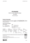
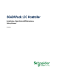
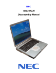
Chapter 1 System Description Specification -1- 1. SCOPE This document describes the functional specifications for the Compal Notebook personal computer NCL60/61 series. The system is hardware and software compatible with the IBM PN/ATX personal computer. 1.1 CPU • Intel SV Arrandale: 2.66GHz, 2.53Ghz, 2.4GHz • Intel i7-620M 2.66GHz, i5-540M 2.53GHz, i5-520M 2.4GHz • Intel i3-430M 2.26GHz, i3-350M 2.26GHz, i3-330M 2.13GHz 1.2 Memory • Support DDR3-800/1066 • Support 2 So-DIMMS, up to Max. 4GB 1.3 Chipset • Intel HM55 1.4 Display • 14" (16:9) LED backlight LCD, 5.2mm Panel 1.5 Keyboard • Chocolate-cap KB • 86/87 keys support with 101/102 key emulation without stick-point • Windows key, Application key Standard pitch, 2.5mm travel length • Multi-Language support 1.6 Hard Disk Drive (HDD) • SATA HDD • 9.5mm, 2.5" S-ATA HDD (5400/7200rpm) 1.7 Graphics Chip • NVIDIA N11M-GE2(969pin) with 512MB/1GB VRAM & N11P-LP with 1GB VRAM, optimus graphics support (only for NCL61) 1.8 Audio • HD Audio, Speaker (1*2W), Microphone-in and headphone-out 1.9 Pointing Device • Gesture TP with up/down scroll zone 1.10 I/O Ports -2- • USB 2.0 x 3 • RJ45 x 1 • VGA port x 1 • Microphone-in x 1, Headphone-out × 1 • HDMI x 1 (Option) 1.11 System Status Indicators • 1 Caps Lock (Blue) • 1 Num Lock (Blue) • 1 Power Button LED (Blue) • 1 LED for IDE HDD activity (Blue) • 1 LED for System status (Power On/ Suspend) (Blue) • 1 LED for Battery status (Charging/Full Blue) (While battery capacity <=10%,Amber)) • 1 LED for Blue tooth/Wireless Card (Amber) 1.12 Camera(Option) • NO or 1.3M (w/ Mic) 1.13 Communication • No modem • No PCI-Express • LAN: 10/100,1000 Giga LAN (w/o LED) • Wireless LAN: 802.11 a/b/g/n via Mini-Card (option) • Bluetooth 2.1 1.14 Card reader • 3-in-1 card reader (SD,MMC,MS) USB Interface 1.15 Control Buttons • Power button • Magnetic lid switch control for system standby/ wakeup or suspend/ resume • Kill Switch to On/Off Wireless Device for wireless control 1.16 Security • BIOS Password/ Kensington lock:25KG • Trusted Platform Module :TPM 1.2 (W/O) 1.17 AC Adapter • 65W AC adapter(NCL60) • 90WAC adapter(NCL61) -3- 1.18 Battery • 6-cell battery • 6-cell Li-ion, 18650 type, 4300/4800/4400/5200mAh • Life Cycle: 70% Design Capacity after 300 Cycles in 25degreeC 1.19 Software • Insyde BIOS 1.20 Application • Driver CD W/User Manual 1.21 OS • Windows 7 Ultimate 64bit (32bit&XP Driver ready) 1.22 Mini Card • Half size card 1.23 Regulatory • EMI: FCC-B, CE, CCC, A, C-Tick, VCCI, BSMI • Safety: Compliant to UL/CSA, TUV, CB • PTT: FCC-Part 68, CTR 21 • MDA2005 Compliant /Energy Star /WHQL LOGO -4- 2. Mechanical Specification FOR 14" Notebook 344mm(W)*237.5mm(D)*19.7mm(H Front) &33.4mm (H Rear) 2.2Kg(including: HDD, DVD, and BATT module) 2.1 Option Pack: • AC adapter : • HDD Pack : • BATT (Li-ion) : 317.3(6cell) • BATT (Li-ion) : 355g(6cell) • DVD module: 360.9g 122.9g(9.5mm) 217.1g 2.2 Mechanical Function • Removable HDD. • Module (DVD, BATT ) • Battery changeable (Li-ion). • For security can use Kensington Lock. • Scissor type key board standard pitch 3.0 m/m travel length. 2.3 Mechanical Material -5- • Plastic PC+ABS (Mitusbishi /8906C9-MB8800) • Mitusbishi/BK30-TMB1615 ABS+PC+15% TALC • BABYER DP3002 PC+ABS Chapter 2 Software Specification -1- 1. System Components Summary - Intel SV Arrandale: 2.66GHz, 2.53Ghz, 2.4GHz Processor - Intel i7-620M 2.66GHz, i5-540M 2.53GHz, i5-520M 2.4GHz - Intel i3-430M 2.26GHz, i3-350M 2.26GHz, i3-330M 2.13GHz Chipset - System Memory - Support DDR3-800/1066 - Support 2 So-DIMMS, up to Max. 4GB - 14" (16:9) LED backlight LCD, 5.2mm Panel Display HDD Audio On-board Comms Keyboard Pointing Device Web Cam(Option) I/O Ports Control Buttons AC adapter Battery Software Operating System -2- Intel HM55 - SATA HDD - 9.5mm, 2.5" S-ATA HDD (5400/7200rpm) - HD Audio, Speakers (1*2W), Microphone-in and headphone-out - No modem - No PCI-Express - LAN: 10/100, 1000 Giga LAN(w/o LED). - Wireless LAN: 802.11 a/b/g/n via Mini-Card (option) - Bluetooth2.1 - Chocolate-cap KB. - 86/87 keys support with 101/102 key emulation without stick-point - Windows key, Application key Standard pitch, 2.5mm travel length - Multi-Language support - Gesture TP with up/down scroll zone - NO or 1.3M (w/ Mic) - USB x 3 - RJ45 x 1 - VGA port x 1 - Microphone-in x 1, Headphone-out × 1 - HDMI X 1(Option) - Power button - Magnetic lid switch control for system standby/ wakeup or suspend/ resume - Kill Switch to On/Off Wireless Device for wireless control - 65W AC adapter(NCL60) 90WAC adapter(NCL61) 6-cell battery 6-cell Li-On, 18650 type, 4300/4800/4400/5200mAh Life Cycle: 70% Design Capacity after 300 Cycles in 25degreeC Insyde BIOS Windows 7 Ultimate 64bit (XP Driver ready) 2. System Controls 2.1 Buttons 2.1.1 Power Button The activity of the power button is as follows: • If system is Off/Hibernate: System will be turned on while Power switch is depressed by more than 100 ms • If system is in Standby state: System will resume while Power switch is depressed by more than 100 ms. • If system on with legacy mode: depress this button will turn off power. If system is running in ACPI OS, the power button acts as the sleep button, and let OS controls the policy of power button which is defined in Power Option under the OS. 2.1.2 Power Button Over-ride Holding down the Power Button for 4 seconds will cause an unconditional transfer to the off state without notifying the operating system. 2.1.3 Lid switch If the system is running under legacy mode: • Closing the lid will turn off LCD backlight. If the system is running under ACPI mode: • The operating system will determine what action to take when the lid is opened and closed. The function of lid switch will follow the OS setting in power management (Nothing, Standby or Hibernate). If nothing, the backlight must turn off when the lid is closed. 2.1.4 System status indicators Please refer to Keyboard BIOS specification. -3- 3 Core BIOS Features 3.1 Multi Boot The notebook can support Multi-Boot for selecting the boot sequence of Hard Drive, Removable Devices, CD-ROM/DVD Drive and Network in Setup. 3.2 Quiet Boot Quiet Boot replaces the customary technical messages during POST with a more visually pleasing and comfortable display (OEM screen). During POST, right after the initialization of VGA, The notebook displays an illustration called the OEM screen during system boot instead of the traditional POST screen that displays the normal diagnostic messages. The OEM screen stays up until just before the operating system loads unless: • Pressing <Esc> to switch to the POST screen and the boot process will continue until the end of POST. • Pressing <F2> to enter Setup. • Pressing <F12> to enter Boot Menu. • Whenever POST detects a non-terminal error, it switches to the POST screen near the end of POST, just prior to prompting for a password. • If the BIOS or an option ROM request keyboard input, the system switches over to the POST screen with prompts for entering the information. POST continues from there with the regular POST screen. 3.3 Boot Block The Flash ROM used in many systems today offer the customer the advantage of electronically reprogramming the BIOS without physically replacing the BIOS ROM. This advantage, however, does create a possible hazard: power failures or fluctuations that occur during updating the Flash ROM can damage the BIOS code, making the system unbootable. To prevent this possible hazard, many Flash ROM include a special non-volatile region that can never be erased. This region, called the boot block, contains a fail-safe recovery routine. If the boot block finds corrupted BIOS, it prompts the end user to insert a diskette, from which it loads several files that replace the corrupted BIOS on the Flash ROM with an uncorrupted one. -4- 4. Thermal management Please refer to Keyboard BIOS specification. -5- 5. Power Management for ACPI mode 5.1 Introduction The notebook supports ACPI. The system will dynamically switch to ACPI mode for configuration and power management when an ACPI OS is loaded. When ACPI is not loaded and enabled, the power management function will be disabled. 5.2 System Time-outs If the system is running in ACPI mode, system Time-outs is handled by the operating system. BIOS time-outs are disabled. System time-outs are set using the control panel power applet. 5.3 System Power Management The overall system can be in one of the system power states as described below: ACPI mode Mech. Off (G3) Soft Off (G2/S5) Working (G0/S0) S3 Sleeping State S4 Sleeping State Power Management All devices in the system are turned off completely. OS initiated shutdown. All devices in the system are turned off completely. Individual devices such as the CPU and hard disk may be power managed in this state. CPU set power down VGA Suspend New Card Suspend Audio Suspend Hard Disk Power Down ODD Power Down Super I/O Power Down System Saves all system states and data onto disk prior to power off the whole system. 5.4 Device Power Management Under ACPI mode, the device specific power management supported by this notebook includes the CPU throttling, monitor power management and the hard disk. 5.4.1 CPU power management • ACPI mode The operating system detects when the system is idle and places the CPU in one of the 3 CPU low power states (C1, C2, C3) depending on how much latency it believes the system can afford. The C1 state is simply the CPU halt instruction. The C2 state is the CPU stop grant state. The C3 state is the CPU stops clock state. The CPU stays in this state until an interrupt occurs. -6- 5.4.2 Hard Disk The operating system uses the spin down timer of the hard drive to set time-outs. The BIOS time-out of the hard disk must be disabled in ACPI mode. The user can sets the hard disk spin down time-out in the control panel power applet. 5.4.3 Display Device The monitor can be turned off after a period of no activity based on the settings of the OS. 5.4.4 System Wake Up Sources The table below lists the wake up events for all low power states: Events S3 S4 S5 Process required Any key Yes No No No Power button Yes Yes Yes No LAN (On board) Yes Yes No Yes RTC Yes Yes No Yes Critical low battery No No Yes Yes Field ‘Process Required’ identifies that further process for the occurred events must be processed during wake up or resume procedure. 5.4.4.1 LAN LAN (On board) S3(Standby): LAN is supported wake-up from S3 w/ AC/DC mode S4(Hibernation): LAN just only support wake-up from S4 w/ AC only S5: LAN is supported wake-up from S5 w/AC. Real Time Clock Alarm The Real Time Clock alarm interrupt will wake the system from Standby (DC/AC) / Hibernation (AC mode) Critical Low Battery Critical low battery event can wake the system from Standby (DC mode) in ACPI mode. 5.5 Hibernation To support the hibernate state, the save to disk partition or file will be created by the operating system if the user select to enable the hibernation. It is the responsibility of the operating system to save the system state to a disk file and restore the system state when it is turned back on. -7- 6 ACPI (Advanced Configuration and Power Interface) 6.1 Introduction The Advanced Configuration and Power Interface (ACPI) is a well-specified power management and configuration mechanism. It evolves the existing collection of power management codes, APM, PnP BIOS, and Etc. 6.2 ACPI Sleep Status BIOS must support the following sleep states – S3, S4 and S5. 6.3 Fast Resume BIOS must hands off the control to the operating system within the following time limits: S3->S0 Required 2seconds *Measured using the Microsoft VTS (Velocity) tool. In addition, total resume time from S3 must be completed within 5 seconds. 6.4 Power State Transition Diagram The state transition diagram in ACPI mode is as follows: From (State) Leave By Condition S3 Power Button Enter (State) S0 On board LAN Any key Alarm Critical low battery(Only in DC mode) S4 Power Button S0 On board LAN (Only in AC mode) RTC(Only in AC mode) S5 Power Button S0 S0 Press Lid switch (depends on ACPI OS setting) S3 Standby icon in shutdown menu in Windows. ACPI OS timer expired Critical low battery (depends on ACPI OS setting) S0 Press Lid switch (depends on ACPI OS setting) Press Power Button (depends on ACPI OS setting) -8- S4 S0 Press Lid switch (depends on ACPI OS setting) S5 Press Power Button (depends on ACPI OS setting) 6.5 Storage Devices and Batteries Possible storage devices are FDD, HDD, CD-ROM and DVD-ROM • Floppy Disk and Hard Disk, CD-ROM and DVD-ROM The BIOS must report the correct types of these devices if the drive is installed in the system during POST. Two devices, which belong to the same category, are not supported in this notebook. • Batteries The BIOS must follow ACPI specification and report the correct number of the installed battery and status. 6.6 Bootable Device The system is capable of booting from onboard HDD, CD ROM, DVD-ROM, external USB Floppy and USB ATA Flash device. 6.7 Embedded controller The keyboard controller will act as the ACPI embedded controller and support the ACPI EC protocol and interface. -9- 7. PC2001 The notebook must meet Microsoft Logo requirements in accordance with the PC2001 Guide and the Microsoft Logo test programs. - 10 - 8. Miscellaneous Features 8.1 Single BIOS ROM Intel: Before Calpella platform: Sharer ROM: The System BIOS and Keyboard BIOS are combined; Rom size is depended on project design, 2M or 1M. After Calpella platform: Non-Sharer ROM: The Size of System BIOS is 2MByte (Include BIOS and Ignition ME) The Size of Keyboard BIOS is 128K (EEPROM is inside EC BIOS area) AMD: Sharer ROM: The System BIOS and Keyboard BIOS are combined; Rom size is depended on project design, 2M or 1M. 8.2 USB Support This feature allows the use of a USB keyboard to access BIOS Setup and to be used in DOS without additional drivers. USB floppy boot and Crisis Recovery from USB floppy is also supported. The driver provides other USB devices support after loading the operating system. 8.3 Flash utility – one BIOS ROM only The flash utility can be used to program both system and keyboard BIOS at the same time. 8.4 Crisis Recovery This feature provides an opportunity for system that cannot boot up. With a crisis floppy diskette, the system can perform crisis recovery by using internal PS2 keyboard. To perform crisis recovery using keyboard, do the following: Power off the system. Plug-in the USB floppy drive with crisis floppy diskette inserted. Hold down Fn + B keys. Plug-in AC adapter and make sure it is powered. Power on the system from off state (i.e. cold boot) while holding down <Fn+B> key. After POST, release <Fn+B> key. The system should boot from floppy and perform crisis recovery action. 8.5 VGA Support This section describes the expected behavior when a video monitor is connected to the VGA port on the notebook .The feature needs VGA driver support The BIOS will use both the RGB and pin 11 methods to determine the presence of an external VGA monitor. Video modes supported on the secondary display path (need VGA driver support) Supported video modes and timings please refer to the technical reference of VGA vendor. In particular, text mode and standard VGA modes are not supported. - 11 - 9. Customer Specific Features 9.1 Display of System Type and BIOS Version Number on Boot BIOS Version V1.00* Note: * The numbers of BIOS version will be changed. 9.2 CMOS RAM management For UEFI Code, CMOS just reserve for kernel code/Chipset code, the variable storage had been replaced by flash part 9.3 System Management BIOS(SM BIOS) version 2.4 (DMI 2.0) Limited DMI 2.0 BIOS information are provided: BIOS version number is type 0 data item. Type 1: • System serial number – 64 alphanumeric characters with 12-character bundle number • System manufacturer name –‘COMPAL’16 alphanumeric characters • System product name – 32 alphanumeric characters • System version – 32 alphanumeric characters • UUID – 32 Hexadecimal numbers Type 2: • System manufacturer name – 16 alphanumeric characters • Motherboard Product name – ‘XXX’ • System serial number – 64 alphanumeric characters with 12-character bundle number Type 3: • System manufacturer name – 16 alphanumeric character • System serial number – 64 alphanumeric characters with 12-character bundle number • Asset tag number – 128 alphanumeric characters 9.4 EEPROM There is one EEPROM that is used to store many important system and user data in the notebook (some data are reserved for future to use)). The size of the EEPROM is 2K bytes. The EEPROM map is listing as below: Name Offset Comments System Serial Number 00h – 1Fh 32 bytes of Serial number. 20h – 3Fh 32 bytes of Bundle number. 40h – 4Fh 16 bytes for DMI type 1/2/3 Manufacturer name - 12 - System version 50h – 6Fh 32 bytes of System version for DMI type 1. UUID 70h – 7Fh 16 bytes for UUID for DMI type 1. System product name 80h – 9Fh 32 bytes of System product name. DMI type 11 A0h – DDh 62 bytes for DMI type 11 Unused DEh – DFh Unused GUID E0h – E7h 8 bytes for GUID Born On Date E8h – EAh 3 bytes for born on date Reserved EBh - EFh Reserved Keyboard type F0h Define for US/UK/JP keyboard Keyboard BIOS used F1h 1 byte for Keyboard BIOS used Branding F2h 1 byte for Branding. Process ID for factory F3h – F4h Identification ID for test process control Reserved for keyboard F5h – F6h Reserved 2 bytes for keyboard used Unused F7h – FDh Unused EEPROM initialized flag FEh Set to AAh when the EEPROM get initialized. Assettag number 200h – 23Fh 64 bytes for DMI Type 3 LAN MAC Address 240h – 245h 6 bytes for LAN without EEPROM Unused 246h – 25Fh Unused ACPI OEM ID 260h – 265h 6 bytes for ACPI OEM ID Unused 266h – 26Fh Unused ACPI OEM Table ID 270h – 277h 8 bytes for ACPI OEM Table ID Reserved 278h - 7FFh Reserved - 13 - 10. System Setup 10.1 Invoking setup The setup function can be invoked by pressing F2 when “Press <F2> to enter Setup” message is prompted on the bottom of screen during POST. During setup, all Fn function keys and power saving functions are disabled. 10.2 Setup screens 10.2.1 Main Menu InsydeH20 Setup Utility Main Security Boot Exit System Time [12:00:00] System Date [01/01/2009] Processor Type Type,XXXGHZ Total Memory XXX MB System BIOS Version X.XX.XX F1 Help Esc Exit ↑↓ Select Item ←→ Select Screen Details see the following Help Information F5/F6 Change Values F9Setup Defaults Enter Select 4SubMenu F10 Save and Exit System Time and System Date The hour is displayed with 24-hour format. The values set in these two fields take effect immediately. Processor Type This field shows CPU type and speed. Total Memory This field reports the memory size of the extended memory with an integer in the system. Help information System Time [hh:mm:ss]This is the help for the hour field. Range is from 0 to 23. INCREASE/REDUCE:+/-. - 14 - [hh:mm:ss]This is the help for the minute field. Range is from 0 to 59. INCREASE/REDUCE:+/-. [hh:mm:ss]This is the help for the second field. Range is from 0 to 59. INCREASE/REDUCE:+/-. System Date [mm:dd:yy]This is the help for the month field. Range is from 1 to 12.(Error checking will be done against month/day/year combinations that are not supported.) INCREASE/REDUCE:+/-. [mm:dd:yy]This is the help for the day field. Range is from 1 to 31.(Error checking will be done against month/day/year combinations that are not supported.) INCREASE/REDUCE:+/-. [mm:dd:yy]This is the help for the year field. Range is from 2000 to 2099.( Error checking will be done against month/day/year combinations that are not supported.) INCREASE/REDUCE:+/-. 10.2.2 Security Menu This menu shows the security setting, Supervisor Password, HDD Password and Power on Password. InsydeH20 Setup Utility Main Security Boot Exit Supervisor Password Clear Set Supervisor Password Power on Password [Disabled] HDD Password Status No Accessed help information Set HDD Password F1 Help ↑↓ Esc Exit ←→Select Screen Select Item Details see the following F5/F6 Change Values F9 Setup Defaults Enter Select 4SubMenu F10 Save and Exit Supervisor Password Show the Password status: Clear or Set Set Supervisor/ HDD Password Install or Change the password. The length of password should not be greater than 8. Power on Password Enable or disable the Power on Password. You only can enable/disable Power on password after the Supervisor password is set. HDD Password Status - 15 - This item will show HDD Password Status. Help information Set Supervisor Password Install or change the password and the length of password must be greater than one word. Power on password Enable: System will ask input password on post time. Disable: System will ask input pass word when go to Setup Utility. Set HDD Password Lock Harddisk and the length of password must be greater than one word. - 16 - 10.3 Boot Menu This menu allows the user to decide the order of boot devices to load the operating system. Bootable devices include the diskette drive in module bay, the onboard hard disk drive in module bay. InsydeH20 Setup Utility Main Security Boot Exit Boot priority order: Floppy Drive : XXXXXXXXXX Hard Disk Drive : XXXXXXXXXX Details see the following CD/DVD-ROM Drive:XXXXXXXXXXX Help Information USB HDD : XXXXXXXXXX USB CDROM : XXXXXXXXXX Network boot: XXXXXXXXXX F1 Help ↑↓ Esc Exit ←→ Select Screen Select Item F5/F6 Change Values F9 Setup Defaults Enter Select 4SubMenu F10 Save and Exit Help information Use <↑>or <↓> to select a device, then press <F5> to move it down the list, or <F6> to Move it up the list. Press <Esc> to escape the menu 10.2.4 Exit Menu InsydeH20 Setup Utility Main Security Boot Exit Exit Saving Changes Exit Discarding Changes Load Optimal Defaults Details see the following Help Information - 17 - F1 Help ↑↓ Esc Exit ←→ Select Screen Select Item F5/F6 Change Values F9 Setup Defaults Enter Select 4SubMenu F10 Save and Exit Exit Saving Changes Allows the user to save changes to NV Storage and reboot system. The following message is prompted when user press “Enter” on the item. Exit Saving Changes? [Yes] [No] Yes: Save Changes, Exit SETUP and reboot No: Back to previous screen Exit Discarding Changes Allows the user to discard changes and continue the boot operation. The following message is prompted when user press “Enter” on the item. Exit Discarding Changes? [Yes] [No] Yes: Discard Changes and Continue the boot operation. No: Back to previous screen. Load Optimal Defaults Allows the user loads default value in CMOS Setup. The following message is prompted when user press “Enter” on this item: Load Optimal Defaults? [Yes] [No] It still stay in Setup when press a key. Help information Exit Saving Changes Exit system setup and save your changes. Exit Discarding Changes Exit system setup and without saving your changes. Load Optimal Defaults Load Optimal Defaults. - 18 - 11. OS Compatibility Windows 7 Ultimate 32bit (XP Driver ready) - 19 - Chapter 3 Hardware -1- 1. Major Sub-assembly Specification System interconnection (For NCL60/61) 1.1 Top View NO -2- Description 1 Speaker Coon 2 Power button board Coon 3 T/P Coon 4 K/B Coon 5 USB board Coon 6 3 in 1 reader 1.2 Bottom view -3- NO Description NO Description 7 Battery Conn 14 Mini PCI Conn 8 LVDS Conn 15 RAM Conn(H5.2) 9 FAN Conn 16 Ram Conn(H9.2) 10 RJ45 Conn 17 SATA ODD Conn 11 D-SUB Conn 18 SATA HDD Conn 12 USB Conn 19 B/T Conn 13 HDMI Conn 20 CPU Socket Chapter 4 DC-DC CONVERTER -1- 4.1 DC/DC Power Plane 4.1.1 UMA V_min +3VALWP +3.135V +5VALWP +4.75V +1.5VP +1.455V +1.05VSP +0.9975V +0.75VSP +0.7125V +VCC_CORE 0.8V Fast Charge (LI12.54V ION) Trickle charge 12.54V VIN current +18V Protection: OVP: +5VALWP : V_typ +3.3V +5.0V +1.5V +1.05V +0.75V 1V V_max Vripple +3.465V 0.15V +5.25V 0.2V +1.545V 0.09V +1.1025 0.1 +0.7875V 0.05V 1.55V 0.05V I_min 0A 0A 0A 0A 0A 0A I_typ 2.1A 3.2A 5.7A 6A 0.6A 26A I_max 3A 4.6A 7.2A 7.8A 2A 40A I_peak 4.3A 6.5A 8A 10A 2A 44A 12.6V 12.66V 0.1V 3.866A 3.886A 3.886A 3.886A 12.6V +19V 12.66V +20V 0.1V 0.1V 220mA 220mA 220mA 0A 2A 2.736| 220mA 3.42A 112.5%~117.5% +3VALWP : 112.5%~117.5% +1.5VP : 111%~119% +1.05VCCP : 111%~119% +CPU_CORE : Vo>1.675V OCP: +5VALWP : 10.8A +3VALWP : 7.36A +1.05VCCP : 13.8A +1.5VP : 10.8A +CPU_CORE : 48A 4.1.2 Interface between Power with M/B DC/DC Signals I/O FSTCHG I Voltage Level 0~3.3V IREF SYSON SUSP# VR_ON SUSP VR_ON EC_ON# VS I I I I I I I O 0~3.3V 0~3.3V 0~3.3V 0~3.3V 0~3.3V 0~3.3V 0~3.3V 0~3.3V O O O I 0~3.3V 0~3.3V 0~3.3V 0~3.3V SMB_EC_CK1 SMB_EC_DA1 BATT_TEMP CHGVADJ Description High Active, system use this signal to control ISL6251 charge action High Active, system use this signal to control charge current High Active, system use this signal to enable +1.5vp output High Active, system use this signal to enable +1.05vccp output High Active, system use this signal to enable +vcc_core output High Active, system use this signal to enable +0.75vsp LDO. High Active, system use this signal to enable cpu_core output Low Active, use this signal to power on system on battery mode When Adapter plug in high active, when battery only low active, use this signal to power on. High Active, system detector battery signal. High Active, system detector battery signal. High Active, system detector battery signal. High Active, system use this signal to control charge voltage. Battery Socket: Socket: CONN 200275MR009G180ZR 9P SUYIN(TBD) Pin1/Pin2: BATT+: Battery positive power pin. Pin3: ID: Floating. Pin4: B/I: Enable LI-ION battery output, connect a 1K resistor to GND in system. Pin5: SMC: SMBUS Clock pin Pin6: SMD: SMBUS Data pin Pin7: TS: Battery temperature detector pin Pin8/Pin9: GND: battery ground power pin. -2- 4.2 Battery Specification 4.2.1 EE information Battery Design Capacity(mAH) Battery Configuration Battery Nominal Voltage(V) Single Cell Chemistry Single Cell Type Single Cell Capacity(mAH) Dumb/Smart Battery Cycle Life Nominal Charging Voltage(V) Nominal Charging Current(A) Protection Function 6 cell 4300 6cell 4400 3S2P 11.1 Li-ion 18650 2150 Smart Battery (SMBus ver. 1.1.) 70% after 300 cycles 12.6 3S2P 11.1 Li-ion 18650 2200 Smart Battery (SMBus ver. 1.1.) 70% after 300 cycles 12.6 3.0 3.08 OVP UVP OTP OCP OVP UVP OTP OCP 4.2.2 Battery Connector Pin Assignment Connector Male on M/B : TBD Connector Female on Battery : SUYIN-200274FS009GX01ZU [TBD] Pin No. Symbol Comments 1 BATT+ Battery Positive Terminal. 2 BATT+ Battery Positive Terminal. 3 ID Identify pin(Floating) 4 B/I Battery-In Function Pin(*) 5 SMC SMBus clock interface I/O pin. 6 SMD SMBus data interface I/O pin. 7 TS Connect to Thermistor 8 GND Battery Negative Terminal. Battery Negative Terminal. 9 GND *: Battery cannot be charged or discharged unless this pin is connected to GND. -4- 4.3 AC Adapter 1. SCOPE This specification describes the physical, functional and electrical characteristics of the 65 watts, single output +19V/3.42A, switching power supply. 2. INPUT CHARACTERISTICS 2.1. Input Voltage Input voltage range : 90~265Vrms. 2.2. Input Frequency Input frequency range : 47~63 Hz 2.3. Input current Input current should be lower than 1.6/0.85Arms under full-load and 100/240 Vrms input voltage conditions. 2.4. Inrush Current Inrush current should be less than 220A and no damage under full-load and cold start at 25 ,240 Vrms input voltage. 2.5. Leakage Current The total combined leakage current shall not exceed 100 microamperes when tested at 240 Vrms, 50 Hz and not exceed 50 microamperes when tested at 100 Vrms, 60 Hz in a normal operating condition. 2.6. Power Consumption Input power saving should be lower than 0.5 Watts under No-load and 115/230 Vrms input voltage conditions. It would be conformed to ENERGY STAR standard. 2.7. Efficiency Output current 3.42A/2.56A/1.71A/0.85A; input voltage 115/230Vrms, sum of each efficiency division 4 should be greater than 85%. It would be conformed to ENERGY STAR standard. 3. OUTPUT CHARACTERISTICS 3.1. Output Characteristics Output voltage, load current, voltage regulation and output noise of power supply should meet the specifications, which defined on the tables below: Table 1 Electrical Characteristics overview Item Performance Remarks Output Voltage Rating 19Vdc Output Range 18.5V~20V Note1 Full Load 3.42A Min. Load 0.0A Peak Load 4.5A Vo regulation:18.0V~20.0V/5 minutes duration @100Vac and 240Vac, 25 Max. Ripple Voltage (300mVp-p) Note2 Line Regulation 1% Dynamic Load Vpp 1.8V Note3 Hold up Time 5 mS Min. Full Load & 115Vac /60Hz input, Phase 90 degree. Vo:18.05Vdcmin@amb=25 Note 4 Rise Time 30 mS Max. Full Load & 115Vac /60Hz input @amb=25 Note 4 Turn on Time 2S Max. Full Load & 115Vac /60Hz input (Operating Temp.: 5 C to 40 C) Note4 Note 1: Full load regulation is within the specification of output tolerance. 3.2. Output Protection : 3.2.1. Short Circuit Protection : The power supply shall be latch off and no damage for shorting rail to Secondary. But the power supply shall recover automatically when the Short is removed. 3.2.2. Over Voltage Protection : Power supply shall be latch off, before output voltage reached 26V. And the power supply shall not recover automatically unless the AC reset. Test condition: 230Vac/0.5A load. 3.2.3. Over Current Protection : Power supply shall be latch off, before output current reached 5.5A. But the power supply shall recover automatically when the over current is removed . 3.2.4. Over Temperature Protection : No deformation and no discoloration on case . 3.3. Overshoot: Output overshoot during power-on and power-off shall not exceed 20V. 4. ENVIRONMENT SECTION 4.1. Operating Temperature : 5 C to 40 C 4.2. Operating Humidity : 20% to 80% RH 4.3. Storage Temperature : -20 C to 85 C 4.4. Storage Humidity : 5% to 95% RH -6- Chapter 5 Disassembly Guide 1. Disassembling the Base Unit These are the directions for disassembling the base unit. You will need a 5.5mm Nut Driver, a medium size Philips screwdriver. These directions are to disassemble the complete unit and are cross-referenced to Chapter 7 for the replacement of component parts. Before disassembly, make sure the notebook is powered off. 1.1 upper and lower disassemble 1.1.1 To remove the battery pack from the battery bay, follow the steps below: Turn the notebook upside down. Slide the battery lock to unlock the battery pack. Slide the battery release latch in the direction of the arrow; gently pry the battery pack from its housing. NOTE: Always start laptop disassembly by removing the battery pack first. -1- 1.1.2 Removing the thermal Door Follow the steps below to remove the thermal door: Turn the notebook upside down. Remove the 4 screws securing the bottom cover. 1.1.3 Disassemble ODD Module: Release and take off 1 screw on bottom cover as below, then use screw drive push the ODD bracket along ODD direction: 1.1.4 Disassemble HDD module Release and take off two screws as below: Take off HDD door from slot as photo: 1.1.5 Disassemble Bluetooth Take out Bluetooth follow below red line, then follow the photo, pull out the Bluetooth connector gently. -3- 1.1.6 Take off WIFI card, RAM, Fan, Thermal module, CPU. Remove RF connector and two screws and take off WIFI module. Push the latches to release the RAM module, and a spring will force one end of the module up, then take off the RAM by two hands as photo: Remove two screws and release fan connector then take off fan module: To remove thermal module, remove two screws as follow red color direction firstly. Then release four thermal screws follow below order: 4Æ3Æ2Æ1 hen take off the thermal module as following the red line in photo, and please be note the thermal fin must be integrity! Use single type screw driver unlock the CPU in below direction: -5- 1.1.7 Remove LVDS cable as below direction: 1.1.8 Disassemble lower 9pcs screws 1.1.9 Disassemble strip cover Reverse the machine first, and disassemble strip cover from left to right sides as below photo, then take off strip cover by up and down. 1.1.10 Disassemble Keyboard Use hand pull up Keyboard and open up Keyboard latch by upwards, turn down the keyboard, and release the cable from lower. 1.1.11 Disassemble power board Remove two screws and take off the power board gently, then pull out the power board FFC and Touchpad FFC as photo: 1.1.12 disassemble upper Use hand loose hook 1 and use fixture open hook 2, then hook 3 as below photo, Along the red arrow direction to disassemble upper: -7- 1.1.13 Disassemble USB module Loose the hook then use thumb remove the USB board as photo, then disassemble the USB cable. 1.1.14 Disassemble M/B Release two screws and the speaker connector, then loose DC-in cable as the below red line direction. 1.1.15 Disassemble speaker module Remove two screws and disassemble speaker module. -9- 1.1.16 Separate LCD to lower Remove two screws and loose LVDS cable and WL cable then apart LCD and Lower 1.2 LCD Part 1.2.1 Disassemble LCD bezel 1.2.2 Disassemble LCD panel Remove four screws and separate panel from cover as below: Turn over the panel and remove LVDS cable connector. 1.2.3 Disassemble wireless cable and LVDS, camera cable Disassemble wireless cable, first tear out AL-foil part then remove Wireless module Remove camera module 1.2.4 Disassemble LCD hinge - 11 - 1.3 Upper disassemble Remove one screw and take off the Touchpad FFC, then take off bracket and touchpad board 1.4 HDD ODD module disassemble 1.4.1 HDD disassemble Remove 4 screws as below photo: 1.4.2 ODD disassemble Remove two screws and take off ODD bracket, then follow the red arrow direction loosen ODD bezel hook. - 13 - Chapter6 Testing and Troubleshooting 1. Testing and Troubleshooting The purpose of this chapter is to provide a systematic method of isolating problems you may have with the NCL6X series Notebook Computer. We assume that you have a basic understanding of DOS-based computer systems as well as knowledge of standard troubleshooting procedures. This manual is written under the assumption that the problems are indeed related with Notebook itself. The improper usage and application software problems are excluded in this chapter. The system BIOS Beep Code is an integrated unit to detect some errors in the system board. This beep code will give immediate identification of certain system board problems. If the troubleshooting procedure is followed step by step, it can efficiently isolate the problem and the problem can be solved easily. 1.1 PERFORM VISUAL INSPECTION Check the following: • • • • • Power cords are properly connected and secured Power supply is adequate for operation There are no obvious shorts or opens There are no obviously burned or heated components All components appear normal 1.2 Troubleshooting Flowchart Use the flowchart in Figure 6-1 as a guide for determining which troubleshooting procedures to execute. Before going through the flowchart steps, verify the following: • Ask the user if a password is registered and, if it is, ask him or her to enter the password. • Verify with the customer that Win7 is installed on the hard disk. Operating systems that were not preinstalled by Compal can cause the computer to malfunction. • Make sure all optional equipment is removed from the computer. • Make sure the floppy disk drive is empty. -2- Figure 6-1 Troubleshooting flowchart (1/2) -3- Figure 6-1 Troubleshooting flowchart (2/2) -4- If the diagnostics program cannot detect an error, the problem may be intermittent. The test program should be executed several times to isolate the problem. When a problem has been located, perform the appropriate troubleshooting procedures as follows: If an error is detected by the main battery test, perform the Power Supply Troubleshooting procedures in Section 6-2. If an error is detected by the display test, perform the Display Troubleshooting procedures in Section 6-3. If an error is detected by the keyboard test, perform the Keyboard Troubleshooting procedures in Section 6-4. If an error is detected when using an external USB device, perform the External USB Devices Troubleshooting procedures in Section 6-5. If an error is detected when using the CRT connection, perform the CRT Failure Troubleshooting procedures in Section 6-6. If an error is detected when using the HDMI connection, perform the HDMI Failure Troubleshooting procedures in Section 6-7. If an error is detected when using the touch pad, perform the Touch Pad Troubleshooting procedures in Section 6-8. If an error is detected when using the speakers, perform the Speaker Troubleshooting procedures in Section 6-9. If an error is detected when using the CD/DVD drive, perform the CD-ROM/DVD Drive Troubleshooting procedures in Section 6-10. If an error is detected when using the Wireless LAN unit, perform the Wireless LAN Troubleshooting procedures in Section 6-11. If an error is detected when using the Camera, perform the Camera Troubleshooting procedures in Section 6-12. If an error is detected when using the Bluetooth, perform the Bluetooth Troubleshooting procedures in Section 6-13. -5- 2. Power Supply Troubleshooting Figure 6-2 Power Supply Troubleshooting Process -6- The power supply controls many functions and components. To determine if the power supply is functioning properly, start with Procedure 1 and continue with the other Procedures as instructed. The flowchart in Figure 6-2 gives a summary of the process. The procedures described in this section are: Procedure 1: Power status check Procedure 2: Adaptor / battery replacement Procedure 3: Power supply connection check Procedure 4: Diagnostic check Procedure 5: Internal connection check Procedure 1 Power Status Check The following LEDs indicate the power supply status: Battery LED The power supply controller displays the power supply status through the Battery and the POWER LEDs as listed in the tables below. Table 2-1 Battery LED Battery State Charging LED colors blue, blinking blue, solid on color off Discharging Amber, blinking LED on for 1 second every 4 seconds Amber, blinking (LED on 1 second every 2 seconds) Color off Definition Battery charging with AC Battery fully charged by AC Battery abnormal: stop charging with AC (Bad cell/ Overheated) Battery within low state: 12 minutes remaining Battery within critical low state: 3 minutes remaining. The system is protected and cannot be re-powered on without the AC power connected. Battery not in low or critical low state; in discharging state Table 2-2 POWER LED Power supply status System Power On (LED is solid blue). System Suspended POWER LED blue Solid on Blue blinking System Power Off. Off To check the power supply status, install a battery pack and connect an AC adaptor to the DC-IN port on the computer and to a power supply. If the Battery LED is not lit, go to Procedure 2 Procedure 2 Adaptor / battery replacement A faulty adaptor may not supply power or may not charge the battery. Perform Check 1. -7- Check 1 Connect a new AC adaptor. If the problem is not resolved, go to Check 2. Check 2 Insert a new battery. If the problem is still not resolved, go to Procedure 3. Procedure 3 Power supply connection check The power supply wiring diagram is shown below: Any of the connectors may be disconnected. Perform Check 1. Check 1 Disconnect the AC power cord from wall outlet. Check the power cable for breaks. If the power cord is damaged, connect a new AC power cord. If there is no damage, go to Check 2. Check 2 Make sure the AC adaptor cord and AC power cord are firmly plugged into the DC-IN socket, AC adaptor inlet and wall outlet. If these cables are connected correctly, go to Check 3. Check 3 Make sure that the DC-IN input port socket is firmly secured to the system board of the computer. If the DC-IN input socket is loose, go to Procedure 5. If it is not loose, go to Check 4. Check 4 Use a millimeter to make sure that the AC adaptor output voltage is close to 19 V. If the output is several percent lower than 19 V, go to Check 5. If the output is close to 19 V, go to Check 6. Check 5 Connect a new AC adaptor or AC power cord. If the battery LED does not light, go to Check 6. Check 6 Make sure the battery pack is installed in the computer correctly. -8- If the battery is properly installed and the battery LED still does not light, go to Procedure 4. Procedure 4 Diagnostic check The power supply may not charge the battery pack. Perform the following procedures: Reinstall the battery pack. Attach the AC adaptor and turn on the power. If you cannot turn on the power, go to Procedure 5. Run the Diagnostic test following the procedures described Tests and Diagnostics. If no problem is detected, the battery is functioning normally. Procedure 5 Replacement check The system board may be disconnected or damaged. Disassemble the computer following the steps described Replacement Procedures. Check the connection between the AC adaptor and the system board. After checking the connection, perform Check 1: Check 1 Use a millimeter to make sure that the fuses on the system board are not blown. If a fuse is not blown, go to Check 2. If a fuse is blown, go to Check 3. Check 2 Make sure that the battery cable is firmly connected to the system board. If it is connected firmly, go to Check 3. Check 3 The system board may be damaged. Replace it with a new one following the instructions in Chapter 4. -9- 3. Display Troubleshooting Figure 6-3 Display troubleshooting process - 10 - This section describes how to determine if the computer’s display is functioning properly. The process is outlined in Figure 6-3. Start with Procedure 1 and continue with the other procedures as instructed. Procedure 1: External display check Procedure 2: Diagnostic check Procedure 3: Connector and replacement check Procedure 1 External display check Connect an external display to the computer’s external monitor port, then boot the computer. The computer automatically detects the external display. Press Fn+F3 to switch to the external display. If the external display works correctly, the internal LCD may be damaged. Go to Procedure 3. If the external monitor appears to have the same problem as the internal monitor, the system board may be damaged. Go to Procedure 2. Procedure 2 Diagnostic check The Display Test program is stored on the computer’s Diagnostics disk. This program checks the display controller on the system board. Insert the Diagnostics disk in the computer’s floppy disk drive, turn on the computer and run the test. Refer to Chapter 3, Tests and Diagnostics for details. If an error is detected, go to Procedure 3. If an error is not detected, the display is functioning properly. Procedure 3 Connector and replacement check The FL inverter board, LCD module, and system board are connected to the display circuits. Any of these components may be damaged. Replacement Procedures, for instructions on how to disassemble the computer and then perform the following checks: Check 1 Make sure the DDRRAM module is seated properly. Test display again. If the problem still exits, replace the DDRRAM module. If the problem still exists, perform check 2. Check 2 Replace the FL inverter board with a new one and test display again. If the problem still exists, perform Check 3. Check 3 Replace the LCD module with a new one and test display again. If the problem still exists, perform Check 4. Check 4 Replace the LCD/FL cable with a new one and test display again. If the problem still exists, perform Check 5. Check 5 Replace the CPU with another of the same specifications. If the problem still exists, perform Check 6. Check 6 The system board may be damaged. Replace it with a new one. - 11 - 4. Keyboard Troubleshooting Figure 6-4 Keyboard troubleshooting process - 12 - To determine if the computer’s keyboard is functioning properly, perform the following procedures. Figure 6-5 outlines the process. Start with Procedure 1 and continue with the other procedures as instructed. Procedure 1: External keyboard check Procedure 2: Diagnostic check Procedure 3: Connector and replacement check Procedure 1 External keyboard check Connect a USB keyboard to one of the computer’s keyboard/mouse ports, then boot the computer. The computer automatically detects the external keyboard. If the external keyboard works correctly, the internal keyboard or its connections may be faulty. Go to Procedure 2. If the external keyboard appears to have the same problem as the internal keyboard, the system board may be damaged. Procedure 2 Diagnostic test Run the Diagnostic Program, which will automatically execute the Keyboard Test. Refer to Chapter 3, Tests and Diagnostics for more information on how to run the program. If an error is located, go to Procedure 3. If an error does not occur, the keyboard is functioning properly. Procedure 3 Connector and replacement check The keyboard and/or system board may be disconnected or damaged. Replacement Procedures and perform the following checks. Check 1 Make sure the keyboard cable is firmly connected to the system board. If the connection is loose, reconnect firmly and repeat Procedure 2. If there is still an error, go to Check 2. Check 2 The keyboard may be damaged. If the problem still exists, perform Check 3. Check 3 The system board may be damaged. Replace it with a new one. - 13 - 5. External USB Devices Troubleshooting Figure 6-5 External USB device troubleshooting process - 14 - To determine if the computer’s external USB devices are functioning properly, perform the following procedures. Figure 6-5 outlines the process. Start with Procedure 1 and continue as instructed. Procedure 1: External device and connection check Procedure 2: Replace system board Procedure 1 External device and connection check The USB device may be damaged or the connection may be faulty. Perform Check 1. Check 1 Make sure USB device cable is firmly plugged into one of the USB sockets. If the cable is connected correctly, go to Check 2. Check 2 Plug the USB device into another USB socket (there are three in all). If the USB device still does not work, go to Check 4. If the device functions correctly when connected to another USB port, go to Check 3 Check 3 Make sure that the USB socket is firmly secured to the system board of the computer. If the malfunction remains, the system board may be damaged. Go to Procedure 2. Check 4 Connect an alternative USB device to one of the computer’s USB ports, and then boot the computer. The computer automatically detects the external device. If the alternative USB device works correctly, the original device may be damaged and should be replaced. If the alternative USB device appears to have the same problem as the original device, the system board may be damaged. Go to Procedure 2. Procedure 2 Replace system board If the error persists, the system board may be damaged. - 15 - 6. CRT troubleshooting Figure 6-6 CRT troubleshooting process - 16 - To determine if the computer’s CRT port is functioning properly, perform the following procedures. Figure 6-6 outlines the process. Start with Procedure 1 and continue as instructed. Procedure 1: CRT connection check Procedure 2: CRT set check Procedure 1 CRT connection check The CRT cable may be damaged or the connections may be loose. Perform Check 1: Check 1 Make sure CRT cable is firmly plugged into both the CRT set and the CRT port of the computer. If the cable is connected correctly, go to Check 2. Check 2 Make sure the CRT port is firmly secured to the system board of the computer. If the malfunction remains, go to Check 3. Check 3 The CRT cable may be damaged. Replace with a good cable. If the malfunction remains, go to Procedure 2 Procedure 2 CRT set check The CRT set may be faulty. Perform Check 1 Check 1 Try using the set for CRT reception. If it does not work, the set may be damaged. If the set does work, perform Check 2. Check 2 Try connecting a different CRT to the computer. If the replacement television works, the original set may be damaged. If the replacement set does not work the system board may be damaged - 17 - 7. HDMI troubleshooting Figure 6-7 HDMI troubleshooting process - 18 - To determine if the computer’s HDMI port is functioning properly, perform the following procedures. Figure 6-7 outlines the process. Start with Procedure 1 and continue as instructed. Procedure 1: HDMI connection check Procedure 2: HDMI set check Procedure 1 HDMI connection check The HDMI cable may be damaged or the connections may be loose. Perform Check 1: Check 1 Make sure HDMI cable is firmly plugged into both the HDMI set and the HDMI port of the computer. If the cable is connected correctly, go to Check 2. Check 2 Make sure the HDMI port is firmly secured to the system board of the computer. If the malfunction remains, go to Check 3. Check 3 The HDMI cable may be damaged. Replace with a good cable. If the malfunction remains, go to Procedure 2 Procedure 2 HDMI set check The HDMI set may be faulty. Perform Check 1 Check 1 Try using the set for HDMI reception. If it does not work, the set may be damaged. If the set does work, perform Check 2. Check 2 Try connecting a different HDMI to the computer. If the replacement television works, the original set may be damaged. If the replacement set does not work the system board may be damaged. - 19 - 8. Touch Pad Troubleshooting Figure 6-8 Touch Pad troubleshooting process - 20 - To determine if the computer’s built-in Touch Pad is functioning properly, perform the following procedures. Figure 6-8 outlines the process. Start with Procedure 1 and continue as instructed. Procedure 1: Touch Pad connection check Procedure 2: Touch Pad replacement check Procedure 1 Touch Pad connection check The Touch Pad is connected by the Touch Pad FPC to the system board. Make sure the Touch Pad FPC cable is firmly connected to the Touch Pad and system board. Replacement Procedures for instructions on how to disassemble the computer and then perform the following checks. If any of the connections are loose, reconnect firmly. If any of the connections is damaged, or there is still an error, go to Procedure 2. Procedure 2 Touch Pad replacement check The Touch Pad unit or FPC may be defective or damaged. - 21 - 9. Speaker Troubleshooting Figure 6-9 Speaker troubleshooting process - 22 - To determine if the computer’s built-in speakers are functioning properly, perform the following procedures. Figure 6-8 outlines the process. First adjust the speaker volume to an appropriate level. Start with Procedure 1 and continue as instructed. Procedure 1: Audio source test Procedure 2: Earphone test Procedure 3: Connection check Procedure 4: Replacement check Procedure 1 Audio source test Try different audio sources (e.g. an audio CD and digital music file) to determine whether the fault is in the speaker system or not. If not all sources have sound problems, the problem is in the source devices. If all have the same problem, continue with Procedure 2. Procedure 2 Earphone test Connect a set if earphones or external speakers. If these function correctly, go to Procedure 3. If they do not function correctly, the system board may be defective or damaged. Replace it with a new one. Procedure 3 Connection check Disassemble the computer following the steps described Replacement Procedures and make sure the speaker cable is firmly connected to the system board. If the stereo speakers are still not functioning properly, go to Procedure 4. Procedure 4 Replacement Check If the stereo speakers don't sound properly, the stereo speakers may be defective or damaged. Replace them with new ones. If the stereo speakers still do not work properly. - 23 - 10. CD-ROM/DVD Troubleshooting Figure 6-10 CD-ROM/DVD drive troubleshooting process - 22 - This section describes how to determine if the computer’s internal DVD-ROM drive or CD-RW/DVDROM drive is functioning properly. Figure 6-10 outlines the process. Perform the steps below starting with Procedure 1 and continue with the other procedures as required. Procedure 1: Audio CD test Procedure 2: Drive cleaning check Procedure 3: Software check Procedure 4: Diagnostic test Procedure 5: Connection and replacement check Procedure 1 Audio CD check First, insert an audio CD into the CD/DVD drive. If it works, the problem is not with the drive. Go to Procedure 3. If the audio CD does not work, go to Procedure 2. If the CD/DVD LED on the front panel does not light when the disc is played and the drive gives no response, go straight to Procedure 3. Procedure 2 Drive cleaning check Insert a CD/DVD drive-cleaning disk into the drive clean according to the drive-cleaning product instructions. If the problem persists, go to Procedure 3. Procedure 3 Software check Ensure that the appropriate driver has been installed on the computer for the CD/DVD drive. Procedure 4 Diagnostic test The CD-ROM/DVD-ROM test program stored in the Diagnostics Disk will test the drive’s ability to play an audio CD, as well as the functions of the CD control buttons. If any errors occur while executing the diagnostic program, go to Procedure 5. Procedure 5 Connection check and replacement check The DVD-ROM drive or the CD-RW/DVD-ROM drive connects to the system board. The drive may be disconnected, or the drive or system board may be damaged. Replacement Procedures and perform the following checks: Check 1 Make sure the drive is firmly connected to the system board. If the connection is good and there is still an error, go to Check 2. Check 2 The drive or drive cable may be defective or damaged. Replacement Procedures. If the drive is still not functioning properly, perform Check 3. Check 3 The system board may be damaged. - 23 - 11. Wireless LAN Troubleshooting Figure 6-11 Wireless LAN troubleshooting process - 24 - The wireless LAN antenna wire, wireless LAN unit or system board may each be the source of a wireless LAN fault. Any of these components may be damaged. To determine if the computer’s wireless LAN system is functioning properly, perform the following procedures. Figure 6-13 outlines the process. Start with Procedure 1 and continue with the other procedures as instructed. Procedure 1: Diagnostic test Procedure 2: Connector and replacement check Procedure 1 Diagnostic test Run the Diagnostic Program, which will automatically execute the wireless LAN test. Refer to Chapter 3, Tests and Diagnostics for more information on the program. If an error is located, go to Procedure 2. If an error is not located, the wireless LAN system is functioning properly. Check 1: Make sure the wireless select switch installed in your installed programs. Check 2: press keyboard “Fn+F2” make sure wireless is enable If the program persist .go to Procedure Procedure 2 Connector and replacement check The wireless LAN antenna, wireless LAN unit or system board may be disconnected or damaged. Disassemble the computer following the steps described in Chapter 4, Replacement Procedures, and perform the following checks. Check 1 Make sure that the wireless LAN antenna is firmly connected to the wireless LAN unit (refer to Chapter 4 for instructions) and that the wireless LAN unit is securely slotted into the system board. If the problem persists, go to Check 2. Check 2 Check that the wireless communication switch is turned to “On”, then make sure that the wireless communication LED on the front panel is lit. If the LED is lit but the wireless LAN function is still faulty, the antenna may be damaged. Replace with a new antenna following the steps in Chapter 4, Replacement Procedures. If the problem persists, or if the wireless LAN LED is not lit when the wireless communication switch is turned to “On”, go to Check 3. Check 3 The wireless LAN unit may be damaged. Replace it with a new one following the instructions in Chapter 4. If the problem still exists, perform Check 4. Check 4 The system board may be damaged. Replace it with a new one following the instructions in Chapter. - 25 - 12. Camera function Troubleshooting START Perform camera function (procedure1) Does camera display NG no Camera module is not faulty yes Perform camera module replacement check (procudure 2) Replace system board end Figure 6-12 camera trouble shooting process - 26 - This section describes how to determine if the computer’s camera is functioning properly. Figure 6-12 outlines the process. Perform the steps below starting with Procedure 1 and continue with the other procedures as required. Procedure 1: Camera connection check Procedure 2: blue tooth replacement check Procedure 1 Camera connection check The Camera is connected by the Camera cable to the system board. Make sure the camera cable is firmly connected to the camera board and system board. Replacement Procedures, for instructions on how to disassemble the computer and then perform the following checks. If any of the connections are loose, reconnect firmly. If any of the connections is damaged, or there is still an error, go to Procedure 2. Procedure 2 Camera replacement check The camera board or cable may be defective or damaged. - 27 - 13. Blue tooth function Troubleshooting Figure 6-13 blue tooth trouble shooting process - 28 - This section describes how to determine if the computer’s blue tooth is functioning properly. Figure 613 outlines the process. Perform the steps below starting with Procedure 1 and continue with the other procedures as required. Procedure 1: blue tooth connection check Procedure 2: blue tooth replacement check Procedure 1 blue tooth connection check The blue tooth is connected by the blue tooth cable to the system board. Make sure the blue tooth cable is firmly connected to the blue tooth device and system board. Replacement Procedures, for instructions on how to disassemble the computer and then perform the following checks. If any of the connections are loose, reconnect firmly. If any of the connections is damaged, or there is still an error, go to Procedure 2. Procedure 2 blue tooth replacement check The blue tooth device or cable may be defective or damaged. - 29 -