1
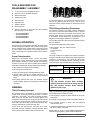
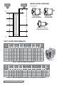
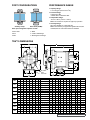
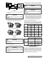
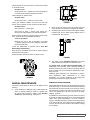
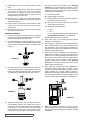
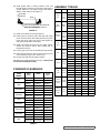
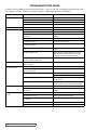
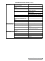
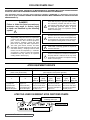
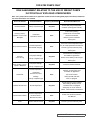
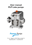
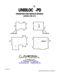
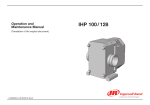
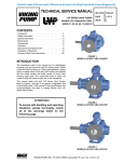
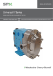
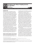
SAFETY INFORMATION
INCORRECT INSTALLATION, OPERATION OR MAINTENANCE OF EQUIPMENT MAY CAUSE SEVERE
PERSONAL INJURY OR DEATH AND/OR EQUIPMENT DAMAGE AND MAY INVALIDATE THE WARRANTY.
This information must be read fully before beginning installation, operation or maintenance and must be
kept with the pump. All installation and maintenance must be undertaken by suitably trained or qualified
persons only.
Symbol
Legend :
!
!
Danger - Failure to follow the listed
precautionary measures identified by
this symbol may result in serious injury
or death.
DO NOT OPERATE PUMP IF:
– The front cover is not installed correctly.
!
DO NOT place fingers, etc. into the pumping chamber
or its connection ports or into any part of the drive train
if there is ANY possibility of the pump shafts being
rotated. Severe injury will occur.
!
DO NOT exceed the pumps rated pressure, speed, and
temperature, or change the system/duty parameters
from those for which the pump was originally supplied,
without confirming its suitability for the new duty.
WARNING
!
!
WARNING
INSTALLATION AND OPERATION OF THE PUMP
MUST ALWAYS COMPLY WITH HEALTH AND
SAFETY REGULATIONS.
A device must be incorporated into the pump, system,
or drive to prevent the pump exceeding its stated duty
pressure. It must be suitable for both directions of
pump rotation where applicable. Do not allow pump
to operate with a closed/blocked discharge unless a
pressure relief device is incorporated. If an integral
relief valve is incorporated into the pump, do not allow
re-circulation through the relief valve for extended
periods.
The mounting of the pump or pump unit should be
solid and stable. Pump orientation must be considered
in relation to drainage requirements. Once mounted,
shaft drive elements must be checked for correct
alignment. Rotate pump shaft by at least one full
revolution to ensure smoothness of operation.
Incorrect alignment will produce excessive loadings
and will create high temperatures and increased noise
emissions.
The installation must allow safe routine maintenance
and inspection (to check for leakage, monitor
pressures, etc) and provide adequate ventilation
necessary to prevent overheating.
Before operating the pump, be sure that it and all
parts of the system to which it is connected are clean
and free from debris and that all valves in the suction
and discharge pipelines are fully opened. Ensure that
all piping connecting to the pump is fully supported
and correctly aligned with its relevant connections.
Misalignment and/or excess loads will cause severe
pump damage.
Be sure that pump rotation is correct for the desired
direction of flow.
WARNING
WARNING
– Any guards are missing or incorrectly installed.
– The suction or discharge piping is not connected.
!
WARNING
DO NOT INSTALL THE PUMP INTO A SYSTEM
WHERE IT WILL RUN DRY (I.E. WITHOUT A
SUPPLY OF PUMPED MEDIA).
SECTION IOM TRA®10
ISSUE
B
PAGE 2 OF 20
!
!
Warning - Safety instructions which
shall be considered for reasons of safe
operation of the pump or pump unit and/
or protection of the pump or pump unit
itself are marked by this symbol.
Pressure gauges/sensors are recommended, next
to the pump suction and discharge connections to
monitor pressures.
Caution must be taken when lifting the pump. Suitable
lifting devices should be used as appropriate. Lifting
eyes installed on the pump must only be used to lift
the pump, not pump with drive and/or baseplate. If
pump is baseplate mounted, the base plate must
be used for all lifting purposes. If slings are used for
lifting, they must be safely and securely attached. For
weights of bare shaft pumps refer to catalog.
DO NOT attempt any maintenance or disassembly of
the pump or pump unit without first ensuring that :
– The pump is fully isolated from the power source
(electric, hydraulic, pneumatic).
– The pumping chamber, relief valve and any shaft
seal support system are depressurized and purged.
– Any temperature control devices (jackets, heattracing, etc) are fully isolated, that they are
depressurized and purged, and components are
allowed to reach a safe handling temperature.
!
!
!
!
WARNING
DO NOT attempt to dismantle a pressure relief valve
which has not had the spring pressure relieved or is
mounted on a pump that is operating. Serious personal
injury or death and/or pump damage may occur.
DO NOT loosen or undo the front cover, any
connections to the pump, shaft seal housings,
temperature control devices, or other components,
until sure that such action will not allow the unsafe
escape of any pressurized media.
Pumps and/or drives can produce sound power levels
exceeding 85 dB(A) under certain operating conditions.
When necessary, personal protection against noise
must be taken.
Avoid any contact with hot parts of pumps and/or
drives which may cause injury. Certain operating
conditions, temperature control devices (jackets, heattracing, etc.), bad installation, or poor maintenance
can all promote high temperatures on pumps and/or
drives.
When cleaning, either manually or by CIP method,
the operator must ensure that a suitable procedure
is used in accordance with the system requirements.
During a CIP cleaning cycle, a pump differential
pressure of between 30 and 45 psi is recommended to
ensure suitable velocities are reached within the pump
head. The exterior of the pump should be cleaned
periodically.
tools required for
disassembly / assembly
1. “O” ring removal tool—supplied with pump
2. Rotor nut wrench—supplied with pump
3. Soft-faced hammer
figure 2
4. Suitable gear puller
5. Allen wrenches
6. Hydraulic press
7. Suitable V blocks
8. Measuring tools
9. Spanner wrenches for gear end lock nuts—available
from Wright Flow Technologies
•WT0150SPWRENCH
•WT0300SPWRENCH
•WT0600SPWRENCH
•WT2200SPWRENCH
The pumped medium is carried around the rotorcase by the
rotors to the discharge side of the pump, here the cavity
decreases and the pumped medium is discharged from the
rotorcase.
TRA10 Range Operating Parameters:
The maximum pressure and speed operating parameters
are given in Pump Performance Tables 2 & 2A. In practice
these may be limited due to the nature of the product to be
pumped and/or design of the system in which the pump is
to be installed. Consult Wright Flow Technologies or your
Wright Flow Technologies distributor for assistance.
normal operation
The operating temperature limit of the pump is determined by
the rotor clearance.
Normal operation of most Wright Flow TRA® 10 Series pumps
is within a range of 0 to 600 rpm, with a pressure range of 0 to
200 psi. Standard rotors operate within a temperature range
of –40°F to 200°F. Hot clearance rotors operate at 200°F to
300°F. Consult factory for operation at other values. Refer to
Table 1.
For the circumferential piston pumps (CPP):
● TRA10 Series - four rotor clearance bands:
a) Standard
b) FF (Front Face)
c) Hot
d) Extra
Pump Characteristics:
The pump should not be subjected to sudden temperature
changes to avoid the risk of damage from sudden expansion/
contraction of components. Care should be taken when
selecting pumps for handling liquids containing abrasive
particles as these may cause wear of pump head components.
Wright Flow Technologies TRA10 pumps are positivedisplacement, low-slip, stainless steel pumps designed with
larger diameter shafts for greater strength and stiffness,
mounted on a heavy-duty cast iron bearing frame (stainless
steel option available) with double tapered roller bearings.
● Up to 200 psi (13.8 bar) pressure capability.
● No bearings in the product zone.
● Heavy-duty bearing frame with large diameter shafts.
●Greased lubed bearings for positive lubrication to all
bearings over entire speed, temperature and pressure
range.
●Non-galling ASTM A-494 rotors are standard; permits
running at tighter clearances and pumping a wide range of
viscosities.
General
TRA10 Pumping Principal:
The pumping action is generated by the counter-clockwise
rotation of two pumping elements (rotors) within a chamber
(rotorcase) - see Figure 2. The rotors are located on shafts,
which in turn are mounted within an external gearbox and
supported by the bearings; the timing gears are also located
on the shafts. The timing gears transfer the energy from the
drive shaft to the driven shaft, synchronising the rotors such
that they rotate without contact with each other.
As the rotors pass the inlet port, see Figure 2, the cavity
generated increases creating a pressure decrease, which
induces the pumped medium to flow into the rotorcase.
Operating Temperature Limit °C (°F)
TRA10 Series
Circumferential Piston
Standard
FF
Hot
Extra
93°C
(200°F)
105°C
(221°F)
150°C
(302°F)
Refer
to WFT
TABLE 1
!
WARNING !
The Net Positive Suction Head available
(NPSHa) from the system must always exceed
the Net Positive Suction Head required
(NPSHr) by the pump.
Observing the following general guidelines should ensure the
best possible suction condition is created.
●Suction piping is at least the same diameter as the pump
connections.
● The length of suction piping is kept to the absolute minimum.
●The minimum number of bends, tees and pipework
restrictions are used.
● Calculations to determine system NPSHa are carried out for
the worst condition, see below.
Should advice on pump or system NPSH characteristics be
required contact the factory or their authorised distributor.
SECTION IOM TRA®10
ISSUE
B
PAGE 3 OF 20
For Suction Lift
Or Vacuum
Conditions.
INSTALLATION POSITIONS
For Conditions
With Positive
Suction Head.
4-Way Mounting
Suction
Head
Atmospheric
Pressure
NPSH
Available
Horizontal ports,
bottom shaft position
10.0 Meters (32.8 F eet) Water C olumn
NPSH
Available
Suction Lift
Or Vacuum
Suction Line
Friction Loss
Suction Line
Friction Loss
Horizontal ports,
top shaft position
Vertical ports, left-hand
or right-hand shaft position
Vapour
Pressure
Vapour
Pressure
Atmospheric
Vacuum
tra®10 pump performance
TRA®10
Model
Displacement
Maximum
per
Pressure
Revolution
Nominal
Capacity
GPM
M3/hr
Gal.
Liter
Deg. C
Optional
Ports
in. mm
Maximum
Speed
(RPM)
in.
mm
6.0
1.3 0.008 0.030 200
14
-40° to 300° -40° to 150° 1.5
38 1.0
25.4
800
0150
9.0
2.0 0.014 0.052 200
14
-40° to 300° -40° to 150° 1.5
38
—
700
0180
17.0
3.8 0.03
14
-40° to 300° -40° to 150° 1.5
38 2.0
51.0
600
0300
36.0
8.2 0.06
0.23
200
14
-40° to 300° -40° to 150° 1.5
38 2.0
51.0
600
0450*
59.0
13.3 0.10
0.38
400
27
-40° to 300° -40° to 150° 2.0
51
—
600
200
Deg. F
Standard
Ports
0060
0.11
PSI Bar
Temperature
Range
—
—
0600
90.0
20.4 0.15
0.58
200
14
-40° to 300° -40° to 150° 2.5
64 3.0
76.0
600
1300
150.0
34.1 0.25
0.96
200
14
-40° to 300° -40° to 150° 3.0
76 4.0 102.0
600
2200
310.0
70.4 0.52
1.98
200
14
-40° to 300° -40° to 150° 4.0 102
—
—
600
3200
450.0 102.0 0.75
2.85
200
14
-40° to 300° -40° to 150° 6.0 152
—
—
600
(Example of Rectangular
Flange model)
table 2 - Pump performance parameters
TRA®10
Rectangular
Flange
Model
0240
Nominal
Capacity
Displacement
Maximum
per
Pressure
Revolution
GPM M3/hr
Gal.
Liter
PSI Bar
0.03
0.11
200
14
Temperature
Range
Deg. F
Deg. C
Inlet (W x L)
in.
-40° to 300° -40° to 150° 1.31 x 4.93
Outlet
mm
in.
mm
33.27 x 125.22
1.5
38.1
Maximum
Speed
(RPM)
11.6
2.5
0340
24.0
5.4
0.06
0.22
200
14
-40° to 300° -40° to 150° 1.75 x 6.75
44.50 x 171.45
2.0
50.8
400
0640
60.0 13.6
0.15
0.57
200
14
-40° to 300° -40° to 150° 2.24 x 8.82
56.90 x 224.03
2.5
57.2
400
75.44 x 234.95
3.0
76.2
400
4.0 101.6
400
1340
100.0 22.7
0.25
0.96
200
14
-40° to 300° -40° to 150° 2.97 x 9.25
2240
200.0 45.4
0.52
1.97
200
14
-40° to 300° -40° to 150° 3.87 x 11.00 98.30 x 279.40
table 2a - Pump performance parameters - rectangular flange models
SECTION IOM TRA®10
ISSUE
B
PAGE 4 OF 20
400
PORT CONFIGURATIONS
PERFORMANCE RANGE
● Capacity Range:
0.1 to 450 gpm (0.02 to 102 m3/hr)
● Pressure Range:
to 200 PSI/14 Bar
* Model 0450 to 400 PSI/27 Bar
● Temperature Range:
-40°F to +300°F (-40°C to +150°C)
Note: Hot clearances required for high temp operation
Sanitary Clamp
● Viscosity Range:
28 to 910,000 SSU (1 to 200,000 cPs)
Note: Consult factory for applications greater than 910,000
SSU/200,000 cSt. Chocolate clearances available.
Bevel Seat (ACME)
Other port configuration options include:
● DIN 11851
●SMS
●RJT
● 150# or 300# flange
●NPT
● Rectangular inlet flange
tra®10 dimensions
OPTIONAL
FOOT
LOCATION
Model
0060
0150
0180
0300
0450
0600
1300
2200
3200
in.
A
B
C
D
E
F
G
H
I
J
K
L
M
N
O
P QØ R
S
Weight
4.75 2.34 3.20 12.04 5.50 1.94 2.31 0.375 x 0.31 (slot) 6.82 2.93 9.61 1.81 2.00 4.21 1.50 2.79 0.875 3.49 6.97 53 lb.
mm
121
in.
4.75 2.34 3.20 12.04 5.50 1.94 2.31 0.375 x 0.31 (slot) 6.82 2.93 9.61 1.81 2.00 4.21 1.50 2.79 0.875 3.49 6.97
59
53 lb.
mm
121
24 kg
59
81
81
303
303
140
140
49
49
59
59
9.5 x 8 (slot)
9.5 x 8 (slot)
173
173
74
74
244
244
46
46
51
51
107
107
38
38
71 22.23 89
71 22.23 89
177
177
24 kg
in.
4.75 2.34 3.20 12.46 5.50 1.94 2.31 0.375 x 0.31 (slot) 6.82 2.93 9.84 1.81 2.00 4.21 1.50 3.02 0.875 3.55 7.09
53 lb.
mm
121
180
24 kg
59
81
316
140
49
59
9.5 x 8 (slot)
173
74
250
46
51
107
38
77 22.23 90
in.
6.25 2.78 4.25 14.52 6.86 2.42 2.56 0.438 x 0.44 (slot) 7.77 3.56 11.61 2.62 2.32 5.21 1.50 3.84 1.250 4.25 8.50
99 lb.
mm
159
45 kg
in.
8.25 4.14 5.87 18.91 9.56 3.50 4.12 0.56 x 0.50 (slot) 10.14 5.06 15.42 3.50 2.15 7.31 2.00 5.28 1.625 5.38 10.75 290 lb.
71
105
108
122
149
9.0
216
229
mm
in.
mm
129
499
243
89
105
105
295
257
129
385
89
59
401
89
55
132
89
55
186
38
55
186
51
98 31.75 108
186
63
134 41.28 136
216
76
127 41.28 136
273
144 41.28 136
273
132 kg
273
132 kg
142 kg
23.29 12.38 3.75 7.25 0.56 x 0.19 (slot) 12.74 6.38 18.49 4.50 2.63 9.38 4.00 5.75 2.000 6.63 13.25 555 lb.
592
314
95
184
12.00 4.12 11.63 30.17 13.88 5.25 8.00
305
14 x 13 (slot)
129
392
67
210
210
258
129
295
8.25 4.79 5.87 19.66 9.56 3.50 4.12 0.56 x 0.50 (slot) 10.12 5.06 15.77 3.50 2.15 7.31 3.00 5.65 1.625 5.37 10.75 312 lb.
8.50 5.07
14 x 13 (slot)
258
90
in.
in.
105
14 x 13 (slot)
197
mm
mm
89
105
11 x 11 (slot)
210
243
89
65
8.25 4.14 5.87 18.73 9.56 3.50 4.12 0.56 x 0.50 (slot) 10.14 5.06 15.14 3.50 2.15 7.31 2.50 5.00 1.625 5.37 10.75 290 lb.
480
243
61
in.
149
480
174
mm
105
149
369
766
353
133 203
14 x 5 (slot)
0.66 Ø
16 Ø
324
162
470
114
67
238
102 146 50.80 168
337
252 kg
16.55 6.88 21.92 5.06 4.06 10.38 6.00 5.37 2.375 8.00 16.00 1050 lb.
420
175
557 129 103
264
152 136 60.45 203
SECTION IOM TRA®10
ISSUE
B
406
477 kg
PAGE 5 OF 20
equipment serial number
All Wright Flow Technologies pumps are identified by
a serial number on the gear case nameplate, which is
stamped on the pump body and cover.
!
CAUTION !
The gear case, body, and cover must be kept
together as a unit due to backface, rotor, and
cover clearances. Failure to do so will damage
the pump.
INSTALLATION
Installation should follow good practice to provide the best
performance and must meet local code requirements. All
system components must be correctly sized to provide
satisfactory operation of your Wright Flow Technologies
product.
Consideration must be given to the following in order to
achieve proper installation:
1. Pumps of this type are usually mounted on a base plate
common with the drive unit. Bases may be permanently
mounted, be self-leveling with vibration isolation pads,
have adjustable legs or be portable. Bases should be
level during pump operation.
2. Provide power as required by the motor and controls as
needed for system operation.
↯
WARNING !
Electrical connections must be made by a
registered electrician in accordance with local
codes and standards.
↯
WARNING !
To avoid serious injury or death, do not install
or service pump unless power is off and
locked out.
3. Piping should be supported independently of the pump
to prevent mis-alignment of pump parts that will cause
excessive wear to rotors, bearings and shafts. Use of
thermal expansion (flexible) joints will also minimize
forces exerted on the pump. Inlet and outlet valves
permit servicing of the pump without emptying the entire
system. Inlet piping must not slope toward the pump
in such a way as to cause formation of an air pocket
ahead of the pump. An inlet valve will serve to keep
the inlet line full. This is particularly important with low
viscosity fluids and with frequent starts and stops. With
low absolute inlet pressure, a check on the outlet side
of the pump prevents backflow and minimizes start-up
differential pressure.
SECTION IOM TRA®10
ISSUE
B
PAGE 6 OF 20
ATTENTION
CAUTION !
Operation of the pump with inlet and/or outlet
valves in the closed position can cause
damage to the pump.
4. Welding of fittings is not recommended since warpage
can occur which may effect pump operation and
performance.
5. Overpressure protection must be provided for this pump.
A pump mounted pressure relief valve, a torque limiting
device on the drive or a rupture disc in the discharge
piping are examples. If pump rotation is to be reversed,
pressure protection must be provided on both sides of
the pump.
!
WARNING !
Do not operate pump unless overpressure
protection is installed in discharge piping.
6. Inlet side strainers or traps can be used to prevent
foreign objects from entering and damaging the pump.
Selection should be made based on viscosity to prevent
clogging and restricting the inlet thus causing cavitation
and reduction of flow from the pump.
7. Installation of pressure and/or vacuum gauges at inlet
and/or outlet provide a convenient way to assess pump
operation. Such gauges can indicate if pressure is normal
or not, show changes in pump or system conditions, and
provide indications of flow and changes in viscosity.
8. Pumps and drives ordered from the factory on a common
base plate have been supplied with a flexible coupling
and aligned before shipping. This alignment should
be rechecked after the pump is installed and piping is
complete.
To check units coupling alignment begin with checking
the angular alignment by measuring the gap between
the couplings at four points. Shim the drive assembly
accordingly so the gaps are an equal distance at all
points (Figure 3). Next check the horizontal and vertical
alignment of the couplings using a straight edge. Place
the straight edge along the coupling to ensure that both
sides are concentric with each other (Figure 4).
figure 3
13. Make sure inlet and outlet connections are tightened.
If pump has double seals connect seal flushing piping.
WARNING !
!
Do not operate pump without guards in place.
figure 4
9. Turn pump shaft manually to make sure that the pump
turns freely.
!
WARNING !
Do not put fingers in ports or near rotating
members.
10. Jog motor and observe motor coupling to make sure
pump will turn in the right direction. See Figure 5.
WARNING !
!
Do not put fingers in ports or near rotating
members.
These connections are normally 1/8” female pipe
threads. Liquid used for flushing can be connected of
the seals and discharged to drain on the opposite side.
Flow should be about 1/4 GPM, but may be increased
for high temperature applications, but should be kept as
near to 1/4 GPM as possible to avoid seal damage.
14. Lubrication (Refer to Tables 3 and 4)
Gears are lubricated with oil conforming to ISO 460, SAE
140, AGMA grade 7 or FDA 21 CFR 178.3570 for top or
bottom shaft mounting position and oil is added at the factory.
Oil Amount (gears)
Top Shaft Drive
Bottom Shaft Drive
figure 5
!
WARNING !
Stay clear of motor shaft and coupling when
jogging motor.
11. Lock out power to pump.
12. Connect coupling halves and install coupling guard.
!
WARNING !
To avoid serious injury or death, do not install
or service pump unless power is off and
locked out.
Grease Amount (per fitting)
Model
Top/Bottom
Mount
Side Mount
Front
Rear
0060, 0150,
0180
1.3 oz
(40 mL)
3.3 oz
(100 mL)
0.37 oz
(11 cc)
0.13 oz
(4 cc)
0300
2.0 oz
(60 mL)
4.0 oz
(120 mL)
0.60 oz
(18 cc)
0.21 oz
(6 cc)
0450, 0600,
1300
6.0 oz
(170 mL)
9.5 oz
(280 mL)
0.84 oz
(25 cc)
0.76 oz
(22 cc)
2200
11.0 oz
(320 mL)
20.0 oz
(600 mL)
1.33 oz
(39 cc)
1.03 oz
(30 cc)
3200
17.0 oz
(500 mL)
44.0 oz
(1300 mL)
1.96 oz
(58 cc)
1.16 oz
(34 cc)
table 3 - Lubricating oil and grease amount
Governing
Standard
Suggested
Brand Names
Lubricating Oil
Grease
Conforming to ISO 460 or
SAE 140 or AGMA grade 7,
and FDA 21 CFR 178.3570.
Conforming to ISO 220
or NLGI grade 2,
and NSF USDA-H1
Chevron Lubricating Oil
FM ISO 460
Chevron FM Grease
CSC 2 EP
or equivalent to
Governing Standard
or equivalent to
Governing Standard
table 4 - suggested Lubricating oil
and grease brand
Bearings are greased with grease conforming to ISO 220,
NLGI grade 2 or NSF USDA-H1. Grease bearings after
every 250 hours of operation; change oil every 500 hours.
Where moisture and/or condensation are heavy change oil
and grease more frequently. If temperature is 5°F or below,
bearings should be greased with silicon grease.
SECTION IOM TRA®10
ISSUE
B
PAGE 7 OF 20
STARTUP CHECKLIST
Has protection from high pressure been considered?
See Installation, step 5.
Are pump and all piping clean and free of foreign material,
gaskets, weld slag, bolts etc.?
DO NOT USE PUMP TO CLEAN SYSTEM.
Are connections tightened and leak free?
Is gear drive properly lubricated? See Installation, step 14.
Are all guards in place and secure?
Have seals requiring flushing been supplied with an
adequate supply of clean flushing fluid?
Are all valves open on the discharge side of the pump?
Are all valves open on the inlet side of the pump, and is
the material to be pumped reaching the pump?
Is direction of rotation correct? See Installation, step 10.
Jog or start pump at low speed when possible.
Check to see that pump is performing properly within several
minutes. If problems are detected, see Troubleshooting
Guide.
CLEANING AND MAINTENANCE
Wright Flow Technologies products are designed for
easy removal of the cover, rotors and seals for cleaning
when necessary. See instructions under Pump Head and
Seal Disassembly/Assembly. Cleaning in place is not
recommended.
!
WARNING !
To avoid serious injury or death, do not install
or service pump unless power is off and
locked out.
!
WARNING !
Relieve system pressure before removing
cover or port connections.
ATTENTION
CAUTION !
Handle all parts with care to avoid nicks and
scratches which may affect pump operation.
1. Remove rotor case cover
2. Remove rotor retainers and ensure components are dry
before servicing.
3. With a penlight, inspect shaft threads for contamination. If
soiled, refer to cleaning procedure below
4. Install rotor retainer and use a torque wrench to tighten
torque setting specified in this manual.
5. Install the rotor case cover and use a torque wrench
to tighten cover nuts to torque setting specified in this
manual.
Cleaning Procedure for Circumferential Rotor
and Rotary Lobe Shaft Threads:
1. Remove rotor retainer devices from the shaft.
2. Submerge and soak retainer part/s for 5 minutes in clean
out of place (COP) tank with 2% caustic solution.
3.While wearing the appropriate personal protective
equipment (PPE) scrub the part/s vigorously with a
sanitary bristle brush for two minutes while submerged.
4. Procure a clean sanitary brush of a size that engages
the shaft threads with enough interference to remove
contaminants. While wearing the appropriate PPE. Scrub
the shaft threads vigorously with the sanitary brush while
consistently flushing with a 2% caustic solution using a
spray bottle.
5. Soak all above parts in acid sanitizer for 5 minutes, and
then scrub again.
6. Flush shaft threads with acid sanitizer for 5 minutes using
spray bottle, and then scrub the hole again with the pipe
brush for two minutes.
7. Rinse well with clean water and blow-dry blind tapped
hole with clean air.
8. Swab test to determine cleanliness.
9. Should the swab test fail, repeat steps 2 thru 8 above until
swab test is passed.
PREVENTIVE MAINTENANCE
Simple inspection during cleaning will often detect signs of a
problem before it becomes serious so that it can be corrected
at minimal cost and down-time.
Remove rotors as described in Step 1 of Pump Head and
Seal Disassembly/Assembly. Visually inspect rotor wing
tips for signs of metal-to-metal contact. If present the pump
should be repaired or replaced.
Possible causes:
Cleaning
Worn shaft spline — replace shaft.
Clean per established procedures. Be aware of the cleaning
solution used (see MSDS), and of cleaning solution
temperature. Make sure no residual cleaning solution stays
in the pump.
Note that acidic cleaners have a high metal corrosion rate, so
pump parts should be exposed to these cleaners no longer
than necessary and be completely rinsed.
SECTION IOM TRA®10
Seal Replacement Procedure:
ISSUE
B
PAGE 8 OF 20
Worn rotor spline — replace rotor (usually both parts
wear, often due to running a loose rotor).
Loose or worn gears, key, keyway shaft — inspect and
replace as needed.
Visually inspect the rotor hub where it contacts the shoulder
on the shaft for wear.
Possible cause:
Running loose rotor — replace rotor and correctly tighten
or re-shim shaft to maintain backface clearance.
Inspect shoulder on shaft for wear.
Possible cause:
Running loose rotor — replace or re-shim shaft.
Check gear backlash. Replace nuts and turn shaft with
wrench. There should be no free movement of either shaft.
Possible causes:
Worn gear teeth — replace gear
Gear loose on shaft — remove gear, inspect key,
keyways and shaft. Replace worn parts and retighten.
Check condition of bearings. Hand load (about 30 lbs.) each
shaft. There should be no detectable movement.
figure 7
2. Drain oil, remove gear box cover and inspect gears for
wear, backlash, and looseness. Retighten as needed.
3. Carefully inspect rotors visually for worn splines, bearing
shoulder wear, and for stress cracks. Replace worn or
cracked rotors. See Figure 8.
Cause of movement:
Bearings worn due to lack of lubrication or overload
— replace bearings and ensure adequate lubrication,
reduce hydraulic load.
If gear box disassembly is required, refer to Gear Box
Disassembly and Assembly.
When pump is assembled there must be equal clearance
where shown. See Figure 6.
Follow lubrication intervals as shown in Tables 3 and 4.
figure 8
4. See Table 6 under Standard Clearances and check
radial and back face clearance to determine wear.
See Pump Head and Seal Disassembly/Assembly for
disassembly and assembly. When replacing bearings or
shafts in the field care must be taken to properly shim the
shaft to provide the correct clearances between the rotors,
body and cover.
figure 6
annual MAINTENANCE
Conduct the same checks as above, and in addition do the
following:
1. Check bearings for radial play using a dial indicator as
shown. If indicator reading is equal to or greater than
the rotor to body clearance in Table 6 under Standard
Clearances, replace bearings. See Figure 7.
Operating speed adjustment can compensate for wear in
some applications. When performance is no longer
acceptable, you may take advantage of the Wright Flow
Technologies remanufacturing plan, as follows:
REMANUFACTURING PROGRAM:
Wright Flow TRA10 Pumps may be remanufactured up to four
times depending on use and wear. Remanufactured pumps
are backed with the same warranty as a new pump. Factory
remanufacturing involves body and cover remachining, new
rotors, and replacement of all worn parts such as shafts,
bearings, gears etc.
To facilitate the remanufacturing process contact the factory
to discuss the particular pump(s) to be remanufactured and
obtain return goods authorization. It may be possible to
supply a reconditioned pump in advance of returning a pump
to the factory although not all sizes may be available at any
one time. Be sure to clean and flush pump before returning
it to the factory.
SECTION IOM TRA®10
ISSUE
B
PAGE 9 OF 20
pump head and seal
assembly and disassembly
Before disassembly, lock out power and release pressure
from pump.
!
WARNING !
To avoid serious injury or death, do not install
or service pump unless power is off and
locked out.
!
WARNING !
Relieve system pressure before removing
cover or port connections.
ATTENTION
CAUTION !
Handle all parts with care to avoid nicks and
scratches which may affect pump operation.
1. PUMP HEAD DISASSEMBLY
Remove wing nuts using a soft hammer. Remove cover.
If necessary, tap cover with soft hammer to loosen.
Remove and discard cover “O” ring.
Use wrench supplied to remove rotor nuts. Nuts remove
in a counter clock-wise direction. Hit wrench sharply with
soft hammer to loosen nuts.
Double “O” Ring (See Figure 11)
Remove “O” ring carriers; remove and discard rings
from both carriers and body. Use “O” ring removal tool
furnished.
Single Mechanical Seal (See Figure 12)
Inner Seal:
Remove seal from body. If chipped, scratched or
evidence of cracks, discard seal. Make sure shoulder is
clean; remove burrs if present; remove and discard “O”
rings.
Seal Seat:
Remove seal seat from shaft. If chipped, scratched or
evidence of cracks, discard seal. Make sure shoulder is
clean; remove burrs if present; remove and discard “O”
rings.
Double Mechanical Seal (See Figure 13)
Inner Seal:
Remove seal from body. If chipped, scratched or
evidence of cracks, discard seal. Make sure shoulder is
clean; remove burrs if present; remove and discard “O”
rings.
Outer Seal:
Remove seal from body. If chipped, scratched or
evidence of cracks, discard seal. Remove and discard
“O” rings.
Seal Seat:
Remove seal seat from shaft. If chipped, scratched or
evidence of cracks, discard seal. Make sure shoulder is
clean; remove burrs if present; remove and discard “O”
rings.
Orient rotors perpendicular to each other, then remove
rotor with both wings exposed first. If necessary use
gear puller or hardwood lever to remove rotor from
spline. See Figure 9.
figure 10
SINGLE “O” RING SEAL
figure 11
DOUBLE “O” RING SEAL
figure 12
SINGLE MECH. SEAL
figure 13
DOUBLE MECH. SEAL
figure 9
If fitted with Allen head hold down bolts in the body
remove them, then remove pump body by pulling it
straight off studs. Note that the pump body must be
assembled to the same bearing housing from which it
was removed.
2. SEAL DISASSEMBLY
(For 3200 model pump, consult factory)
Single “O” Ring (See Figure 10)
Remove and discard body and shaft “O” rings. Use “O”
ring removal tool furnished with pump.
SECTION IOM TRA®10
ISSUE
B
PAGE 10 OF 20
3. SEAL ASSEMBLY
(For 3200 model pump, consult factory)
Prior to reassembling the pump head inspect all parts to
make sure they are free from damage. Nicks, scratches
and cracks in mechanical seal components may cause
seal leakage, and nicks, scratches and burrs on any
pump part may cause leakage or performance problems.
Refer to sketches with disassembly instructions.
Single “O” ring (See Figure 10)
Apply a suitable “O” ring lubricant to new “O” rings and
insert them into the body and shaft grooves. “O” rings
on shafts should be installed in the groove closest to the
spline.
Assemble shaft sleeves against shaft shoulder. If sleeve
is slotted, assemble with slot over drive pin in shaft. If
sleeve has prongs assemble with prongs on either side
of drive pin. Do not re-use sleeves that are grooved or
scratched.
Double “O” ring (See Figure 11)
Apply a suitable “O” ring lubricant to new “O” rings and
insert them into the body, carrier and shaft grooves. “O”
rings on shafts should be installed in the groove closest
to the spline when using “O” ring seats. Assemble
carriers into body so carrier notch engages pin in body.
Assemble shaft sleeves against shaft shoulder. If sleeve
is slotted, assemble with slot over drive pin in shaft. If
sleeve has prongs assemble with prongs on either side
of drive pin. Do not re-use sleeves that are grooved or
scratched.
Single Mechanical Seal (See Figure 12)
Seal Seat:
Apply a suitable “O” ring lubricant to new “O” rings and
insert them into shaft grooves furthest from spline.
Install seal seats lining up groove on rear face with shaft
drive pin.
Inner Seal:
Apply a suitable “O” ring lubricant to new “O” rings and
insert them into body grooves.
Assemble wave spring on seal and install into body with
notch engaging pin in body.
Lubricate seal faces.
Double Mechanical Seal (See Figure 13)
Seal Seat:
Apply a suitable “O” ring lubricant to new “O” ring and
insert into shaft groove furthest from spline.
Install seal seat lining up groove on rear face with shaft
drive pin.
Inner Seal:
Apply a suitable “O” ring lubricant to new “O” ring and
insert into body groove.
Assemble wave spring on seal and install into body with
notch engaging pin in body.
Insert seal assembly into body engaging notch with pin
and pushing from opposite side, over and in, to seat “O”
ring.
Apply lubricant to seal faces.
4. PUMP HEAD ASSEMBLY
Slide body over shafts and studs taking care not to
damage seal parts. Press body firmly against gear case
engaging dowels. Install Allen Head body hold down
bolts, where furnished.
Assemble rotor to its shaft engaging the large spline
tooth with large groove in rotor. Rotate shaft until rotor
wings are on a vertical centerline, then install second
rotor. Secure with rotor retaining nuts: tighten first nut
on shaft by striking nut wrench with soft faced hammer,
then tighten second nut against first in the same way to
jam nuts together.
Place cover “O” ring in groove, push cover over studs
making sure “O” ring remains in groove.
Insert a plastic or other soft dowel to clock rotor against
pump body, then tighten each nut by striking with a soft
hammer.
Sterilize pump in accordance with accepted sterilization
procedures. Make sure no residual solution remains in
the pump.
gear box disassembly
and assembly
!
WARNING !
To avoid serious injury or death, do not install
or service pump unless power is off and
locked out.
!
WARNING !
Relieve system pressure before removing
cover or port connections.
GEAR BOX DISASSEMBLY
1. Remove pump head as described in step 1 of Pump
Head and Seal Disassembly/Assembly and drain oil
from gear box.
2. Remove cap screws. Remove cover using soft hammer
to loosen.
3. Scrape sealant from gear box and cover.
4. Remove oil seal from cover using an arbor press. Discard
seal.
5. Using hammer and drift pin straighten locking tab on
lockwashers.
Outer Seal:
6. Prevent shafts from turning by wedging a wooden block
between the gears.
Apply a suitable “O” ring lubricant to new “O” rings and
install on outer diameter of seal.
7. Use a spanner wrench or drift pin to remove the gear
lock nuts.
SECTION IOM TRA®10
ISSUE
B
PAGE 11 OF 20
8. Wrap splines and ends of shafts with tape to protect
them.
9. Remove front bearing retainer bolts. Remove sealant
from retainers and gear box, press out and discard
grease seals. (If retainers are stuck, they will press
out when shaft is removed. Refer to cleaning process
described above once removed.)
10. Place gear box on arbor press with pump head end
down. Protect shaft ends with a wooden block and press
shafts out of gear box.
11. Remove shims. If they will be reused identify the shaft
on which they were used. Press out and discard rear
grease seals.
the rotors and the cover. See Table 6 under Standard
Clearances for these dimensions. Clearance for both
rotors should be equal to avoid rotor-to-rotor contact. To
establish the correct shim thickness, make the following
measurements in 0.001 inches:
A. Measure body width.
B. Measure depth of rotor bore.
C. Measure distance from gear box face to bottom of
front bearing pocket in gear box.
D. Slide rotor onto shaft and measure from back of
rotor to back of front bearing.
Do calculations for shim thickness:
12. Use hydraulic press and V blocks to remove bearings
and spacer. See Figure 15.
A–B=X
GEAR BOX ASSEMBLY
(Y – D) + required backface clearance (from Table 6
under Standard Clearances) = shim thickness.
1. Coat front bearing area of shaft with grease conforming
to ISO 220, NLGI grade 2 or NSF USDA-H1 and position
shaft in hydraulic press with spline down.
2. Place front bearing over shaft with shield side up. Press
onto shaft until bearing is seated against shoulder. Place
bearing spacer over shaft to seat on front bearing. See
Figure 14.
C+X=Y
Repeat measurements for second rotor.
5. Place shim stock in the required thickness against
shoulder in the bearing bore.
6. Place gearbox on arbor press with front (pump) end up.
Place shaft assemblies in gear box with spline end up
and with shafts in the correct location to provide top or
bottom drive as required. Press shafts into housing until
bearing is seated against shims.
7. Place body on gear box, making sure it is firmly seated.
Install rotors on shafts. Secure with rotor retaining nuts:
tighten first nut on shaft by striking nut wrench with soft
faced hammer, then tighten second nut against first in
the same way to jam nuts together. Check back face
clearance against value on Table 6 under Standard
Clearances. If necessary remove rotors, then remove
shafts to adjust shim thickness.
figure 14
3. Coat rear bearing area on shaft with grease conforming
to ISO 220, NLGI grade 2 or NSF USDA-H1. Slide rear
bearing over shaft with shield side down. Press bearing
onto shaft until it seats against spacer. See Figure 15.
8. When back face clearance has been established in
accordance with the value shown in Table 6, remove
body and secure shaft assemblies in the gear box with
bearing retainers. Do not apply sealant at this time.
Retainers must seat firmly against the bearing and leave
.050-.060” clearance between retainer and gear box. Use
shims if needed to obtain this clearance. See Figure 16.
figure 15
figure 16
4. Wright Flow pumps have close running tolerances to
provide efficient operation. The position of the rotors is
controlled by the use of shims behind the front bearing
in the gear box . These shims control both the backface
clearance between the rotors and the bottom of the
rotor pocket in the housing and the clearance between
SECTION IOM TRA®10
ISSUE
B
PAGE 12 OF 20
9. Make sure backface clearance is correct. Remove
bearing retainers and grease both front and rear bearings
through grease fittings until grease is visible around ball
assemblies.
10.Install grease seals in bearing retainers. Coat seal
lips with grease conforming to ISO 220, NLGI grade 2
or NSF USDA-H1. Coat retainer flanges with silicone
sealant. Install retainers. See Figure 17.
SILICONE
SEALANT
SEAL
COAT WITH GREASE, AS STATED IN
GEAR BOX ASSEMBLY STEP 10
ASSEMBLY TORQUE
Description
Location
Wing
Nut
Front
Cover
/ Rotor
Case
Rotor
Retainer *
figure 17
11. Install rear oil seals and rear gear spacers.
12. Please keys into shaft key slots. Slide gear with single
punch mark onto drive shaft. Slide gear with two punch
marks onto short shaft, with punch marks aligned on
each side of single mark of drive gear.
13. Install lock washers and lock nuts onto shafts. Tighten
locknut with spanner wrench. Bend locking tab on
lockwasher to secure.
Socket
Head Cap
Screw
Cap
Screw
14. Press in gear case cover oil seal with lip facing outward.
15. Place silicone sealant on back of gear case and mount
cover assembly on gear case. Secure cover.
Stud
16. Fill gear case with oil as specified in Table 3.
Assemble pump head as described in step 4 of Pump Head
and Seal Disassembly/Assembly.
Locknut
Rotor /
Shaft
Rotor
Case /
Gearbox
Housing
0060
Gearbox
Housing
8
8
8
Size (in)
1-1/4"
1-1/4”
1-1/4”
Torque (N-m)
7.3-8.6
7.3-8.6
7.3-8.6
Torque (lbf-ft)
5.4-6.3
5.4-6.3
5.4-6.3
Qty / Pump
4
4
4
Size (in)
7/8”-8
7/8”-8
7/8”-8
Torque (N-m)
5.4-6.8
5.4-6.8
5.4-6.8
Torque (lbf-ft)
4-5
4-5
4-5
Qty / Pump
2
2
2
Size (in)
1/4"-20
1/4"-20
1/4"-20
Torque (N-m)
8.1-9.5
8.1-9.5
8.1-9.5
Torque (lbf-ft)
6-7
6-7
6-7
Qty / Pump
8
8
8
1/4"-20
1/4"-20
1/4"-20
8.1-9.5
8.1-9.5
8.1-9.5
6-7
6-7
6-7
Qty / Pump
8
8
8
Size (in)
1/4"-20
1/4"-20
1/4"-20
Torque (N-m)
8.1-9.5
8.1-9.5
8.1-9.5
Torque (lbf-ft)
4-5
4-5
4-5
Qty / Pump
2
2
2
Size (in)
N-05
N-05
N-05
67.8-94.92
67.8-94.92
50-70
50-70
Torque (N-m) 67.8-94.92
Torque (lbf-ft)
standard clearances
TRA10
PUMP
SERIES
0060
0150
0180-0240
0300-0340
0450
0600-0640
1300-1340
2200-2240
3200
Back
Face
Radial
Front
Face
0.002 in.
0.003 in.
0.005 in.
0.051 mm
0.076 mm
0.127 mm
0.002 in.
0.003 in.
0.005 in.
0.051 mm
0.076 mm
0.127 mm
0.002 in.
0.003 in.
0.005 in.
0.051 mm
0.076 mm
0.127 mm
0.002 in.
0.003 in.
0.005 in.
0.051 mm
0.076 mm
0.127 mm
0.003 in.
0.005 in.
0.007 in.
0.076 mm
0.127 mm
0.178 mm
0.003 in.
0.005 in.
0.007 in.
0.076 mm
0.127 mm
0.178 mm
0.003 in.
0.005 in.
0.006 in.
0.076 mm
0.127 mm
0.152 mm
0.005 in.
0.006 in.
0.007 in.
0.127 mm
0.05 mm
0.178 mm
0.006 in.
0.007 in.
0.010 in.
0.152 mm
0.178 mm
0.254 mm
Cap
Screw
Socket
Head Cap
Screw
Socket
Head Cap
Screw
Gearbox
Housing
50-70
Qty / Pump
6
6
6
Size (in)
1/4"-20
1/4"-20
1/4"-20
Torque (N-m)
8.1-9.5
8.1-9.5
8.1-9.5
Torque (lbf-ft)
6-7
6-7
6-7
Qty / Pump
Size (in)
Mounting
Flange Torque (N-m)
Finger
Guard
0180
Qty / Pump
Lip Seal
Size (in)
Mounting
Torque
(N-m)
Bracket
Torque (lbf-ft)
Front
Cover /
Gearbox
Housing
0150
4
4
4
5/16"-18
5/16"-18
5/16"-18
14.9-16.3
14.9-16.3
14.9-16.3
Torque (lbf-ft)
11-12
11-12
11-12
Qty / Pump
4
4
4
Size (in)
#8-32
#8-32
#8-32
Torque (N-m) 13.56-27.12 13.56-27.12 13.56-27.12
Torque (lbf-ft)
10-20
10-20
10-20
table 6
SECTION IOM TRA®10
ISSUE
B
PAGE 13 OF 20
ASSEMBLY TORQUE (CONT’D)
Description
Location
Wing
Nut
Front
Cover
/ Rotor
Case
Rotor
Retainer *
Socket
Head Cap
Screw
Cap
Screw
Stud
Locknut
Cap
Screw
Socket
Head Cap
Screw
Socket
Head Cap
Screw
Rotor /
Shaft
Rotor
Case /
Gearbox
Housing
0300
Gearbox
Housing
Gearbox
Housing
8
8
8
Size (in)
2-1/4”
2-1/4”
2-1/4”
Torque (N-m)
7.3-8.6
24.4-26.8
24.4-26.8
Torque (lbf-ft)
5.4-6.3
18.1-9.8
18.1-9.8
SECTION IOM TRA®10
Description
Location
Wing
Nut
Front
Cover
/ Rotor
Case
1300
2200
3200
Qty / Pump
8
8
8
Size (in)
2-1/4”
2-1/4”
2-1/4”
Torque (N-m)
24.4-26.8
24.4-26.8
24.4-26.8
Torque (lbf-ft)
18.1-19.8
18.1-19.8
18.1-19.8
Qty / Pump
4
4
4
Qty / Pump
4
4
4
Size (in)
1-1/16”-8
1-1/16”-8
1-1/16”-8
Size (in)
1-1/16”-8
1-9/16”-8
2-1/4”-8
Torque (N-m)
6.8-8.1
6.8-8.1
6.8-8.1
Torque (N-m)
6.8-8.1
9.5-12.2
14.9-18.9
Torque (lbf-ft)
5-6
5-6
5-6
Torque (lbf-ft)
5-6
7-9
11-14
Qty / Pump
2
2
2
Size (in)
1/4"-20
3/8"-16
3/8"-16
Torque (N-m)
8.1-9.5
27.1-29.8
27.1-29.8
Torque (lbf-ft)
6-7
20-22
20-22
Qty / Pump
8
8
8
Qty / Pump
5/16"-18
3/8"-16
3/8"-16
14.9-16.3
27.1-29.8
27.1-29.8
11-12
20-22
20-22
8
8
8
Size (in)
5/16"-18
3/8"-16
3/8"-16
Torque (N-m)
14.9-16.3
27.1-29.8
27.1-29.8
Torque (lbf-ft)
9-10
18-20
18-20
Qty / Pump
2
2
2
Size (in)
N-07
N-09
N-09
Torque (N-m)
135.6176.28
210.18237.30
210.18237.30
Torque (lbf-ft)
100-130
155-175
155-175
Qty / Pump
6
6
6
Size (in)
1/4"-20
3/8"-16
3/8"-16
Torque (N-m)
8.1-9.5
27.1-29.8
27.1-29.8
Torque (lbf-ft)
6-7
20-22
Qty / Pump
4
4
Size (in)
Mounting
Flange Torque (N-m)
Finger
Guard
0600
Qty / Pump
Lip Seal
Size (in)
Mounting
Torque
(N-m)
Bracket
Torque (lbf-ft)
Front
Cover /
Gearbox
Housing
0450
2
3/8"-16
3/8"-16
Torque (N-m)
27.1-29.8
27.1-29.8
27.1-29.8
Torque (lbf-ft)
20-22
20-22
20-22
Qty / Pump
8
8
8
Lip Seal
Size (in)
Mounting
Torque
(N-m)
Bracket
Torque (lbf-ft)
Front
Cover /
Gearbox
Housing
Gearbox
Housing
Qty / Pump
3/8"-16
3/8"-16
5/16"-18
27.1-29.8
27.1-29.8
14.9-16.3
20-22
20-22
11-12
8
8
8
Size (in)
3/8"-16
7/16"-14
5/8"-11
Torque (N-m)
27.1-29.8
42.0-46.1
124.7-136.9
Torque (lbf-ft)
18-20
29-32
90-99
Qty / Pump
2
2
2
Size (in)
N-09
N-11
N-13
Torque (N-m)
210.18237.30
230.52257.64
230.52257.64
Torque (lbf-ft)
155-175
170-190
170-190
6
6
3/8"-16
Torque (N-m)
27.1-29.8
27.1-29.8
27.1-29.8
20-22
Torque (lbf-ft)
20-22
20-22
20-22
4
Qty / Pump
4
4
4
1/2"-13
Torque (lbf-ft)
20-22
43-47
43-47
Qty / Pump
4
4
4
Size (in)
#8-32
#8-32
#8-32
Torque (N-m) 13.56-27.12 13.56-27.12 13.56-27.12
PAGE 14 OF 20
2
3/8"-16
3/8"-16
58.3-63.7
B
Locknut
2
Size (in)
6
1/2"-13
ISSUE
Stud
Qty / Pump
3/8"-16
58.3-63.7
10-20
Cap
Screw
Rotor
Case /
Gearbox
Housing
Size (in)
3/8"-16
10-20
Socket
Head Cap
Screw
Rotor /
Shaft
Qty / Pump
27.1-29.8
Torque (lbf-ft)
Rotor
Retainer *
10-20
Cap
Screw
Socket
Head Cap
Screw
Socket
Head Cap
Screw
Gearbox
Housing
Size (in)
Mounting
Flange Torque (N-m)
Finger
Guard
1/2"-13
1/2"-13
1/2"-13
58.3-63.7
58.3-63.7
58.3-63.7
Torque (lbf-ft)
43-47
43-47
43-47
Qty / Pump
4
4
4
Size (in)
#8-32
#8-32
#8-32
Torque (N-m) 13.56-27.12 13.56-27.12 13.56-27.12
Torque (lbf-ft)
10-20
10-20
10-20
Care of stainless Steel
ASTM A-494
Stainless steel components used in products made by
Wright Flow Technologies are produced using methods that
preserve the corrosion resistant property of stainless steel.
The following precautions must be observed in use and
cleaning to maintain corrosion resistance:
ASTM A-494 is the standard rotor material for TRA10 CPP
pumps. This alloy was developed specifically for corrosion
resistance and close operating clearance requirements
of high performance rotary positive displacement pumps.
ASTM A-494 is a nickel based, corrosion-resistant, nongalling or seizing material. The ASTM designation is A-494
Grade CY5SnBiM (UNS N26055), and the material is listed in
the 3-A Sanitary Standards as acceptable for product contact
surfaces.
1. Hydrochloric acid, even with added inhibitors, is NOT
recommended for cleaning due to its corrosion producing
properties.
2. Pitting can occur when stray electrical currents contact
wet stainless. Check electrical devices on a regular
basis for improper grounding, damaged insulation or
other defects that might cause stray currents.
3. Objects in contact with stainless steel prevent the air
from drying and reforming the protective oxide film on
the stainless, therefore don’t leave tools, rubber mats
etc. in contact with stainless pump components.
4. Utilize conditioned water where necessary to prevent
foreign matter in the water from causing pitting or
deposits that may prevent thorough cleaning.
5. Immediately rinse equipment with warm water after use,
then clean as soon as possible. Pitting may occur under
particles of product left on pump surfaces.
6. Use only recommended cleaning compounds from
reputable suppliers, and use only as specified by the
manufacturer, to prevent pitting, stress cracking and
surface discoloring.
7. Scratches and metal particles embedded into stainless
may cause corrosion over time. Use only non-metallic
brushes and pads for hand cleaning.
8. Chemical bactericides must be used at the lowest
permissible concentration, temperature and time. Follow
directions supplied by the manufacturer and local health
authority. Chlorine and other halogens may destroy the
protective film while increased temperatures increase
chemical activity which accelerates corrosion. Inspect
joints for properly sealed gaskets in joints; crevices
caused by improperly seated gaskets will promote
crevice corrosion, particularly in the presence of chlorine.
9.
Check all equipment for evidence of pitting and discolored
surfaces and for stress cracks. Remove deposits and
color from surfaces immediately using mild scouring
powder and detergents. Rinse thoroughly and air dry to
promote reformation of the protective oxide film.
The above properties make ASTM A-494 the ideal material
for Wright Flow Technologies CPP pumps. The non-galling
rotors permit close operating clearances in the liquid end.
This provides low slip and minimum shear damage. The
rotors will not gall or seize if they come in contact with the
body or cover during operation.
The corrosion resistance of ASTM A-494 is approximately
equal to AISI 300 Series Stainless Steel. However, ASTM
A-494 has limited resistance to certain aggressive chemicals
that may be commonly used in contact with AISI 300 Series
Stainless Steel.
Do not use ASTM A-494 in contact with nitric acid. Nitric acid
is commonly used to passivate new installations of stainless
steel equipment. Do not allow nitric acid based passivation
chemicals to contact ASTM A-494 rotors. Remove the rotors
during passivation and use a separate pump to circulate the
passivation chemicals. Also, if nitric acid-based CIP cleaning
chemicals are used, remove the rotors prior to CIP cleaning
and clean them separately by hand in a mild detergent.
If you have any questions regarding other aggressive
chemicals, please contact Wright Flow Technologies
Application Engineering for assistance.
ELASTOMER SEAL REPLACEMENT
FOLLOWING PASSIVATION
Passivation chemicals can damage product contact areas of
Wright Flow Technologies equipment. Elastomers (rubber
components) are most likely to be affected. Always inspect
all elastomer seals after passivation is completed. Replace
any seals showing signs of chemical attack. Indications
bay include swelling, cracks, loss of elasticity or any other
noticeable changes when compared with new components.
SECTION IOM TRA®10
ISSUE
B
PAGE 15 OF 20
TROUBLESHOOTING GUIDE
A properly sized and installed pump should provide trouble
free operation, however problems in pumping systems
may occur over time. The following information may help in
identifying and resolving such problems:
POSSIBLE CAUSE(S)
PROBLEM
Pump not turning
SOLUTION(S)
Drive motor not running
Check circuit breakers, fuses
Keys sheared or missing
Replace keys
Drive belts, etc. slipping or broken
Adjust or replace
Shaft or gears sheared
Replace
No flow, pump turning
Rotation in wrong direction
Reverse rotation
No flow, pump not priming
Inlet valve closed
Open valve
Inlet line clogged
Clean line and filters
Air leaks because of bad seals and/or pipe
connections
Replace seals, pressurize lines to check for
leakage
Speed of pump too slow
Increase speed, fill inlet lines, install foot valve
Liquid drains or siphons
Install foot or check valves
Air lock due to fluids that may vaporize or allow gas
to come out of solution
Install air bleed in lines near pump
Excess clearance between rotors and body and
cover
Increase pump speed, install foot valve, have pump
rebuilt
Net inlet pressure too low
Check Net Inlet Pressure Available at Pump and
Net Inlet Pressure Required by Pump. Calculate
system and modify inlet system as needed.
With vacuum inlet system, atmospheric “blow back”
prevents pump from starting flow
Install check valve in discharge line
No flow
Relief valve not properly adjusted or held open by
foreign material
Adjust or clear valve
Fluid vaporization
(starved Pump inlet)
Filters, valves, inlet filters or lines clogged
Clean
Inlet line too small or too long, too many valves or
fittings, filter too small
Make necessary changes
Net Inlet Pressure Available at Pump too low
Increase level in source tank or pressurize tank
Select larger pump with less inlet pressure required
Insufficient flow
Relief valve not adjusted
or held
SECTION IOM TRA®10
ISSUE
B
Viscosity of pump fluid higher than anticipated
Reduce pump speed (lower flow will result) or
modify system
Temperature of fluid higher than anticipated
Provide cooling, reduce speed,
modify system to increase available inlet pressure
Speed too low
Increase speed
Air leaks because of bad seals and/or pipe
connections
Replace seals, pressurize lines to check for
leakage
Adjust/clean
Open
Flow diverted in system
Check system valves and controls
Hot clearance rotors used with “cold” or low
viscosity fluid
Replace with standard rotors
Worn pump
Increase speed, recondition pump
Pressure too high
Modify system
PAGE 16 OF 20
TROUBLESHOOTING GUIDE (cont’d)
Noisy operation
Cavitation due to high fluid Viscosity, high vapor
pressure or high temperature
Reduce speed and/or temperature, modify system
Inlet Pressure Available less than Inlet Press
Required
Modify System
Air or gas in system due to system leaks
Fix leaks
Dissolved gas or naturally aerated products
Reduce discharge pressure, reduce speed and/or
temperature, modify system
Rotor to body contact
Check back face and rotor to cover clearances and
reshim as necessary
Check for distortion of pump due to Installation of
piping. Reassemble pump and/or re-install piping
Pump overheats, stalls,
draws excessive current
(trips breaker, blows fuses)
Pump service life not as
long as expected
Pressure higher than pump is Rated
Reduce pressure
Worn bearings or gears
Replace as needed, ensure regular lubrication
Rotor to rotor contact noise due to twisted shaft,
sheared keys, loose or mistimed gears, worn
splines
Rebuild with new parts as needed
Relief valve chattering
Readjust, repair or replace valve
Drain train components
Lubricate, repair or replace as needed
Higher viscous losses than anticipated
If pump is within rating, increase drive size
Pressure higher than anticipated
Reduce speed, increase line size
Fluid colder than anticipated, high viscosity
Heat fluid/insulate and heat lines, increase running
clearances
Fluid sets up during shutdown
Insulate or heat lines, install recirculating or “soft
start” drive, Flush with different fluid
Fluids such as chocolate, latex build up on internal
pump surfaces
Increase running clearances
Misalignment of drive and piping, excessive pump
overhang
Align piping and drive
Abrasive fluid
Use larger pump at slower speed
Bearings and gears lack lubrication
Establish and follow lubrication schedule
Speeds and pressures higher than pump is rated
Reduce speed and pressures by system
modification
Pump corrodes
Upgrade material used in pump
SECTION IOM TRA®10
ISSUE
B
PAGE 17 OF 20
FOR ATEX PUMPS ONLY
INCORRECT INSTALLATION, OPERATION, OR MAINTENANCE OF EQUIPMENT MAY CAUSE SEVERE PERSONAL
INJURY OR DEATH AND/OR EQUIPMENT DAMAGE AND MAY INVALIDATE THE WARRANTY.
This information must be read fully before beginning installation, OPERATION, or maintenance and must be
kept with the pump. SUITABLY TRAINED OR QUALIFIED PERSONS MUST UNDERTAKE ALL INSTALLATION AND
MAINTENANCE only.
DANGER !
Failure to follow the listed precautionary
measures may result in serious injury
or death are identified by the following
symbol:
!
Insure that the pump is grounded (earthed) with
the connection provided and that the motor,
gear reducer, base plate and other components
are adequately grounded. Failure to ground
equipment may result in an explosion causing
death or serious injury.
!
Provide a means to monitor all sensing equipment.
Failure to do so may cause unacceptable build
up of temperature or pressure which could result
in an explosion causing death or serious injury.
!
Install ATEX conforming guards as required to
meet EC Directives.
!
Conduct all maintenance activities as detailed in
the pump manual. Failure to do so may cause
pump failure could result in an explosion causing
death or serious injury.
!
!
Wright ATEX pumps are sold to be coupled with
a motor, and usually be mounted on a base
plate. The motor, other electrical equipment,
gear reducers, couplings, guards and base
plates must comply with ATEX requirements.
The motor, gear reducer, sensors, and other
associated electrical equipment must bear CE
and ATEX marking. Couplings must be ATEX
marked, and be accompanied by a Certificate
of Conformity. Failure to comply will void ATEX
Certification and may result in an explosion
causing death or serious injury.
ATEX EQUIPMENT GROUPS
Equipment - groups (Annex I of the EC-Directive 94/9/EC)
Group I
(mines, mine gas and dust)
Category M
Group II
(other explosive atmospheres gas/dust)
Category 1
1
2
for equipment providing
a very high level
of protection when
endangered by an
explosive atmosphere
for equipment providing
a high level of
protection when likely
to be endangered by an
explosive atmosphere
G
(gas)
(Zone 0)
D
(dust)
(Zone 20)
for equipment providing a
very high level of protection
when used in areas where
an explosive atmosphere is
very likely to occur
Category 2
G
(gas)
(Zone 1)
D
(dust)
(Zone 21)
for equipment providing
a high level of protection
when used in areas where
an explosive atmosphere is
likely to occur
Category 3
G
(gas)
(Zone 2)
for equipment providing a
normal level of protection
when used in areas where
an explosive atmosphere is
less likely to occur
ATEX TAG USED ON WRIGHT ATEX CERTIFIED PUMPS
Group II
Category 2
Unit is suitable for environments
containing dust or gas
Temperature Class
SECTION IOM TRA®10
ISSUE
B
PAGE 18 OF 20
D
(dust)
(Zone 22)
FOR ATEX PUMPS ONLY
RISK ASSESSMENT RELATING TO THE USE OF WRIGHT PUMPS
IN POTENTIALLY EXPLOSIVE ATMOSPHERES
Note: For a product to be suitable for an application it must be fit for its designated purpose and also be suitable for
the environment where it is installed.
Source Of Hazards
Potential Hazards
Frequency Of Hazards
Unvented cavities
Build up of explosive gas
Very Rare
Housing / Rotors /
Impellers / Front Cover /
Backplate
Unintended
mechanical contact
Recommended Measures
Ensure that pump is totally filled.
Consider mounting ports vertically.
Ensure that operating
pressures are not exceeded.
Rare
Ensure that sufficient
NPSH to prevent cavitation.
Service plan.
User must ensure temperature limits.
Pump external surfaces
Excess temperature.
Electrostatic charging.
Rare
Do not overfill gearboxes with lubricant.
Provide a ground contact for pump.
Service plan.
Housing /
Cover ‘O’ ring
Pump liquid leakage.
Build up of explosive gas.
Very Rare
Check selection of elastomers
are suitable for application.
Ensure cover retaining nuts are tight.
Service plan.
Pump housing / cover /
Impeller / Backplate
Pump liquid leakage.
Build up of explosive gas.
Very Rare
Excess temperature.
Shaft seals
Unintended
mechanical contact.
Selection of seal system must
be suitable for application.
Rare
Leakage.
Rotation direction test
Corrosion resistant materials.
Service as needed.
Build up of explosive gas.
Always provide seal flush
when so equipped.
Excess temperature
Ensure liquid is in pump chamber
before testing / Always provide
seal flush when so equipped.
Very Rare
Allow pump to run for minimum
period - a few seconds / See Manual
Excess Temperature.
Closed valve condition
Excess Pressure.
Rare
Provide over-pressure protection.
See Manual.
Mechanical contact.
Shaft
Random induced current
Very Rare
Provide a ground contact for pump.
SECTION IOM TRA®10
ISSUE
B
PAGE 19 OF 20
INSTRUCTION AND
MAINTENANCE MANUAL
SECTION
IOM TRA® 10
PAGE
20 of 20
SANITARY POSITIVE DISPLACEMENT PUMPS
ISSUE
B
TRA® 10 SERIES
notes
WARRANTY
Wright Flow Technologies warrants all products
manufactured by it to be free from defects in
workmanship or material for a period of one (1) year
from date of startup, provided that in no event shall this
warranty extend more than eighteen (18) months from
the date of shipment from Wright Flow Technologies.
If, during said warranty period, any products sold
by Wright Flow Technologies prove to be defective
in workmanship or material under normal use and
service, and if such products are returned to Wright
Flow Technologies’ factory at Cedar Falls, Iowa,
transportation charges prepaid, and if the products
are found by Wright Flow Technologies to be defective
in workmanship or material, they will be replaced or
repaired free of charge, FOB. Cedar Falls, Iowa.
Wright Flow Technologies assumes no liability for
consequential damages of any kind and the purchaser
by acceptance of delivery assumes all liability for the
consequences of the use or misuse of Wright Flow
Technologies products by the purchaser, his employees
or others. Wright Flow Technologies will assume no
field expense for service or parts unless authorized by
it in advance.
Equipment and accessories purchased by Wright
Flow Technologies from outside sources which are
incorporated into any Wright Flow Technologies product
are warranted only to the extent of and by the original
manufacturer’s warranty or guarantee, if any.
THIS IS WRIGHT FLOW TECHNOLOGIES’
SOLE WARRANTY AND IS IN LIEU OF ALL
OTHER
WARRANTIES,
EXPRESSED
OR
IMPLIED, WHICH ARE HEREBY EXCLUDED,
INCLUDING IN PARTICULAR ALL WARRANTIES
OF MERCHANTABILITY OR FITNESS FOR A
PARTICULAR PURPOSE. No officer or employee of
IDEX Corporation or Wright Flow Technologies, Inc. is
authorized to alter this warranty.
AMERICAS:
Wright Flow Technologies, Inc.
406 State Street
Cedar Falls, Iowa 50613-0008 U.S.A.
Phone: (319) 268-8013 • Fax: (803) 216-7686
E-mail: [email protected]
EUROPE & ASIA:
www.wrightflowtechnologies.com
Wright Flow Technologies Ltd.
Highfield Industrial Estate, Edison Road Eastbourne
East Sussex, United Kingdom BN23 6PT
Phone: +44(0)1323 509211 • Fax: +44(0)1323 507306
E-mail: [email protected]
Wright Flow Technologies, Inc. ● A Unit of IDEX Corporation
406 State Street ● Cedar Falls, Iowa 50613 U.S.A.
©Copyright 2012
Wright Flow Technologies
All rights reserved