1
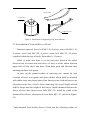
3.7M Dual Reflector
RING-FOCUS ANTENNA
SERVICE MANUAL
Index
Part I. Introduction ......................................................................................2
1.1 Summary .........................................................................................2
1.2 Main Technical Parameters .............................................................3
1.3 Unpacking Check ............................................................................6
1.4 Damage during Transportation .......................................................6
1.5 Installing Tools (shall be provided by user) ...................................7
1.6 Foundation Check ...........................................................................7
Part II. Installation of Antenna ....................................................................7
2.1 Composition of Antenna, shown in Figure 1. .................................7
2.2 Base .................................................................................................8
2.3 Installation of Antenna ....................................................................8
Part III Operation of Antenna's Alignment to Satellite .............................23
3.1 Azimuth Adjustment of Antenna (shown in Figure 5.).................23
3.2 Elevation Adjustment of Antenna (shown in Figure 6.) ...............23
3.3 Determination on Azimuth Angle, Elevation Angle and
Polarization Angle...............................................................................23
Part IV Maintenance and Service to Antenna ...........................................24
Part V Troubleshooting .............................................................................25
1
Part I. Introduction
1.1 Summary
This manual specifies the assembly and installation of the dual
reflector ring focus 3.7-meter antenna system. This 3.7-meter ring-focus
antenna is a new-type small aperture antenna for communication station
under optimum design. It is applicable to be the antenna of remote station
for not only satellite communication but also VSAT networks. This antenna
is available for both C-band and Ku-band; furthermore, it can be put into
use within various domains like scatter communication, reception of
satellite TV, microwave relay communication and so on.
3.7-meter ring-focus antenna adopts new technologies of ring-focus
design method and of corrugated feed horn. After being implemented with
optimum design, its electrical performances reach the advanced level and
overcome the weakness of some traditional design vsat size antenna
performance.
Features of the antenna: The main reflecting surface of antenna is
composed by twelve pieces of high-precision flabellate surface plates
stretched into form with aluminum alloy after quenching. The secondary
reflecting surface is fabricated with precision work. Its pedestal is designed
into stable and reliable structure of upright column. The antenna system has
many unique features such as novel design, high accuracy, excellent
appearance, easy installation, simple operation, high mechanical strength,
strong wind-resistance and high accuracy on re-installation.
2
1.2 Main Technical Parameters
1.2.1 Electrical Specification
Electrical
Specification
C-Receive
C-Transmit
Ku-Receive
Ku-Transmit
Frequency
(GHz)
3.652-4.2
3.4-4.2*
5.85-6.425
5.925-6.725*
12.25-12.75
10.95-12.75*
14-14.5
13.75-14.5*
Gain(dBi)
42
45.2
50.9
52.5
Voltage Standing
Wave Ratio
1.25:1
1.25:1
1.25:1
1.25:1
Beamwidth-3dB
1.32°
0.86°
0.47°
0.38°
-15dB
2.75°
1.73°
0.91°
0.75°
Noise
Temperature
2-Port Feed
2-Port Feed
10°E1
36°K
50°K
20°E1
30°K
44°K
40°E1
25°K
38°K
Power Capacity
5KW/port
1KW/port
WR-75
Interface
CRP-229G
CPR-159G/137G
Insertion Loss of
Feed
0.15dB
0.2dB
Isolation Tx-Rx
Cross Pol
Isolation on Axis
Axial Ratio
(circular)
Sidelobe
Envelope
0.25dB
0.25dB
35dB
35dB
CCIR-580
CCIR-580
85dB
35dB
35dB
1.09
1.09
1.06(IntelSat)
CCIR-580
CCIR-580
* feed provided as per customer request
3
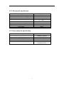
1.2.2 Mechanical Specification
Mechanical Specification
Diameter of Main Reflecting Surface
Diameter of Secondary Reflecting Surface
Travel of Azimuth
Travel of Elevation
Surface Accuracy
Re-Installation Accuracy
Dead Weight of Antenna
Spray Paint
Parameter
D=3.7m
d=0.444m
±60°
5°~90°
0.5mm(r.m.s)
0.6mm(r.m.s)
600Kg
White
1.2.3 Environmental Specification
Environmental Specification
Operational Wind Speed
Survival Wind Speed
Humidity
Temperature
Anti-Seismic Capacity
Parameter
72Km/h~97Km/h
200K/h
10%~98%
-45℃~+60℃
Horizontal: 0.3G’s
Vertical: 0.15G’s
4
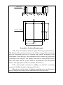
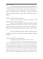
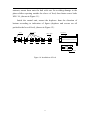
85
7-M30×500
265±1
530±1.5
Direction of Satellite
265±1
530±1.5
Foundation Technical Requirements
1 The level of foundation shall be higher than the ground surface by
200~300mm. The position of anchor bolts shall be arranged for connecting
with the reinforcing steel bar in concrete base strictly according to the
requirement of the drawing. The foundation shall be formed by processing
of casting at one iteration. The anchor bolts shall be kept parallel strictly
with each other, and all of them shall be perpendicular with the ground
surface. The upper plane of the base shall be flat and level.
2 The dead weight of antenna is 600Kg; its maximal overturning
moment is 5500Kg-m (under wind speed of 55m/s).
3 Based on specific status of different installing sites, the foundation
shall be designed according to the conditions offered by this figure.
5
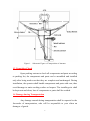
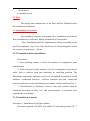
Figure 1. Schematic Figure of Composition of Antenna
1.3 Unpacking Check
Open packing cartons to check all components and parts according
to packing list; the components and parts can be assembled and installed
only after being made sure that they are complete and undamaged. During
installation, the operator shall handle components and parts with care, thus
avoid damage to main working surface or lacquer. The installing site shall
be kept neat and clean; loss of components or parts shall be avoided.
1.4 Damage during Transportation
Any damage caused during transportation shall be reported to the
forwarder of transportation, who will be responsible to your claim on
damages of goods.
6
1.5 Installing Tools (shall be provided by user)
Tools for unpacking
Wire Cutting Pliers
200mm
1piece
Crowbar
1piece
Iron Hammer
3lbs
1piece
Tools for installation
Adjustable Spanner
300mm
150mm
2pieces for each type
450mm
Double-Head Spanner
1piece
19/17
14/12
2pieces for each type
10/8
4pieces
Screwdriver
Flathead 200×5
Crosshead
200×5
Tape Measure
5m
1piece
Rubber Mallet
2”
1piece
Iron Hammer
3lbs
1piece
Geologic Compass
1piece for each type
1piece
Trestle Ladder
2m
1piece
Wire Cutting Pliers
200mm
1piece
1.6 Foundation Check
Check the layout of anchor bolts on the foundation; the arrow
points the approximate direction of satellite.
Part II. Installation of Antenna
2.1 Composition of Antenna, shown in Figure 1.
1 Main reflecting surface (12 pieces of plates)
2 Reflector Radial/bracket (12 pieces)
3 Secondary reflecting surface
4 Feed system
7
5 Feed sleeve
6 Antenna mount
2.2 Base
The design and construction of the base shall be finished before
the installation of antenna.
2.3 Installation of Antenna
The installing sequence of antenna: first, installation of pedestal;
then, installation of reflectors; finally, installation of accessories.
Note: Installation shall be implemented strictly according to the
specified sequence. Any screw bolt should not be fastened/tighten before
the sequence requirement
allows.
2.3.1 Preparation before Installation
Procedures
1. Open packing cartons to check the amount of components, parts
and fasteners.
2. Find concerned serial numbers, lay the components and parts in
order, thus to achieve each part matching its installing position. The
following components and parts need to be assembled according to serial
numbers: connection between
reflector brackets and hub, connection
between reflectors, connection between secondary surface and feed sleeve.
3. Classification of Fasteners: Screws, nuts and washers shall be
classified according to their size and specifications, to facilitate their
applications accordingly.
2.3.2 Installation of mount
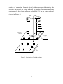
Procedure 1. Installation of upright column
Fasteners required: Nut M30, flat washer 30 and spring washer 30 - 7
8
pieces for each type.
Place the upright column gently onto the foundation with care to
avoid damaging to screw threads of anchor bolts. When the undersurface of
the column fully clings to the foundation, operator shall utilize compass to
check if the upright column is perpendicular to ground surface. After
making sure the perpendicularity, operator shall fasten all nuts. (shown in
Figure 3.)
Procedure 2. Installation of rotary pedestal
Fasteners required: Screw bolt M16×35, flat washer 16 and
spring washer 16 - 4 pieces for each type.
Install the rotary pedestal on the flange located under the upright
column, then mount screw bolt M16×35 (4 pieces). At first, please do not
fasten these bolts; they shall be fastened only after the next procedure is
fulfilled, in which the supporting frame can rotate agilely. (shown in Figure
4.)
In some circumstances the rotary pedestal of antenna has been
assembled before delivery, for which the operator can implement following
procedures:
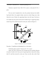
Procedure 3. Installation of supporting frame
Purchasing parts required: Cotter pin Φ5×50 - 1 piece
Lubricate the ball socket of rotary pedestal, mount the lower
button head of supporting frame into the ball socket of rotary pedestal, then
insert the single lug into the position between the double lug located above
the upright column; then according to the size of clearance between lugs,
insert washers of 5mm and 0.5mm into the clearance; after minimizing the
clearance in position A, insert the pin 1# through it, and then mount the
cotter pin. Rotate the supporting frame around the rotary pedestal; if the
9
rotation of supporting frame is found with occurrence of detention, the
operator can knock the rotary pedestal for making the supporting frame
rotates agilely; then fasten all screw bolts M16×35 on the rotary pedestal.
(shown in Figure 5.)
Direction of
Satellite
Upright
Column
Foundation
Figure 3. Installation of Upright Column
10
Upright Column
Rotary Pedestal
Figure 4. Installation of Rotary Pedestal
Washer 1mm,5mm
A
Upright
Column
Supporting
Frame
Pointer for
Azimuth
Rotary Pedestal
Figure 5. Installation of Supporting Frame
11
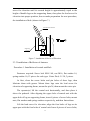
Procedure 4. Installation of
azimuth adjusting device
Fasteners required: Screw M16×20, 8 pieces; cotter pinφ5×50, 1
piece.
Put one end of azimuth device into the position between the double
lug located above the upright column, mount two short flange axes, then
fasten the screws. Rotate the supporting frame, insert the lug of lead screw
for azimuth into the position between the double lugs of supporting frame,
mount the pin 2#, and then mount the cotter pin. (shown in Figure 6.)
Supporting
Frame
Upright
Column
Handwheel
Lead Screw for Azimuth
Figure 6. Installation of Device of Azimuth
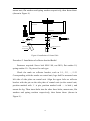
Procedure 5. Installation of adjusting device of elevation
Purchasing parts required: Cotter pinφ5×50, 1 piece.
Insert one end of lead screw for elevation into the position between
two plates located at the lower part of supporting frame, mount the locking
shaft 2#, and then mount the cotter pin. Screw out the other end of lead
12
screw for elevation until its erected height is approximately equal to the
height of double lugs on the supporting frame, then place the lead screw for
elevation into proper position, thus to make preparation for next procedure,
the installation of hub. (shown in Figure 7.)
Lead Screw for Elevation
Supporting
Frame
Figure 7. Installation of Device of Elevation
2.3.3 Installation of Reflector of Antenna
Procedure 1. Installation of central unit/Hub
Fasteners required: Screw bolt M16×60, nut M16, flat washer 16,
spring washer 16; 12 pieces for each type. Cotter Pinφ5×50, 3 pieces.
At first, clean the screw holes and pin holes of three lugs, then
lubricate them with grease. Mount these lugs onto the lead screw for
elevation of supporting frame; mount the pin 2#, then mount the cotter pin.
The operator(s) lift the central unit horizontally, and then place it
above the pedestal. After aligning the upper hole of central unit with the
upper hole of lug on supporting frame, insert 8 pieces of screw bolts, mount
nuts, flat washers and spring washers respectively, and then fasten them.
Lift the lead screw for elevation; align the four holes of lugs on its
upper part with the four holes of central unit. Insert 4 pieces of screw bolts;
13
mount nuts, flat washers and spring washers respectively, then fasten them.
(shown in Figure 8.)
Central Unit
Procedure 2
Pointer for Elevation
Procedure 1
Lug
Supporting Frame
Lead Screw
for Elevation
Figure 8. Installation of Central Unit
Procedure 2. Installation of reflector bracket/Radial
Fasteners required: Screw bolt M16×40, nut M10, flat washer 10,
spring washer 10 - 36 pieces for each type.
Check the mark on reflector bracket, such as 5-1, 5-2, ..., 5-12.
Corresponding with the marks on central unit, legs shall be mounted onto
left side of side plate on central unit. Align the upper hole on reflector
bracket with the pin on the side plate of central unit (on the central unit,
position marked with × is pin, position marked with — is hole.), and
mount the leg. Then insert bolts into the other three holes; mount nuts, flat
washers and spring washers respectively, then fasten them. (shown in
Figure 9.)
14
Procedure 3. Installation of reflectors
Fasteners required: Screw M5×12, 24 pieces; screw bolt M8×30
(with pin), 24 pieces; screw bolt M8×30, 24 pieces; nut M8, 48 pieces; flat
washer 8, 48 pieces.
Check and make sure that the marks on narrow edge of reflector are
corresponding with the marks on central unit, and then stand-by for
installation.
Turn the narrow edge of reflector toward the central unit; then from
outside to the direction of central unit, insert the plate to the position of
flange on the central unit. From above to below, fall the surface plate into
the position between the reinforced beam for upper surface plate of central
unit and the left side of reflector bracket; then fasten the two screws M5×
12 located at the joint between narrow edge of reflector with the flange on
the central unit.
Adopting the same method, mount abutting reflector and fasten the
two screws M5×12. Note: the reinforced beam of surface plate shall be
installed onto the right side of plate of supporting leg.
Mount two screw bolts M8 × 30 (with pin) onto two pieces of
reflectors and supporting leg; at the position B, mount two screw bolts
M8×30; then mount nuts, flat washers and spring washers respectively,
but these parts shall not be fastened for the moment.
Adopting same method, mount all surface plates. During installation,
all parts shall be handled with care. When fastening the screw M5×12, the
operator works inside the central unit, which requires the operator shall
wear soft-sole shoes.
After all reflectors are mounted, fasten all fasteners in the order from
inner cycle to outer cycle. (shown in Figure 9.)
15
Surface Plate
Central Unit
Supporting Leg
Figure 9. Installation of Supporting Legs and reflectors
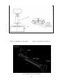
2.3.4 Installation of Feed and Sleeve of Feed
Fasteners required: Screw bolt M8×10, 4 pieces; screw bolt M8×16,
8 pieces; screw bolt M6×20, 8 pieces; screw bolt M4×25, 48 pieces
(supplied within the box of feed); flat washer 8, 12 pieces.
Check to make sure there is no dirt and paint found at the rabbet
between hole of central unit and sleeve of feed, or at the rabbet between
upper hole of feed sleeve and horn. Clean these parts and lubricate their
matching surfaces with grease.
At first, on the ground surface of operating site, mount the feed
(consists of horn, wave-guide and phase shifter, which shall be mounted
with rubber ring) into proper status, then fasten screws (feed and screws are
all packed in the box of feed). After connecting, the overall length of feed
shall be longer than the height of feed sleeve. Install mounted feed into the
sleeve of feed, then fasten screw bolts M6×20. Install the clunk at the
bottom of feed sleeve, then fasten 4 screw bolts M8×10. (shown in Figure.
10)
Take mounted feed and the sleeve of feed into the reflecting surface of
16
antenna, mount them onto the hub with care for avoiding damage to the
phase shifter exposing outside the sleeve of feed, then fasten screw bolts
M8×16, (shown in Figure 11.)
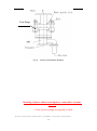
Inside the central unit, mount the duplexer from the direction of
bottom according to indication of figure (duplexer and screws are all
packed in the box of feed), (shown in Figure 12.)
Horn
Wave-Guide
phase shifter
Feed Sleeve
Surface Plate
Figure 10. Installation of Feed
17
Feed
Flange
Duplex
Transmit port
Receive port
Hub
Figure 11. Installation of Feed Sleeve
Figure 12. Installation of Duplexer
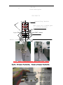
Fig. 13 Feed source system installation
18
Fig. 14 Feed source system installation
Device of Polarization Rotation
Polarization adjusting mode is manual.The polarization adjusting device consists
of rotating flange, upper and lower level of rolling track, which is shown in Fig.
19
Turn-flange
Fig 15. Device of Polarization Rotation
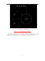
Drawing of phase shifter and duplexer contact(For circular
system)
( View from rectangle waveguide to feed)
Receive R-Circular Polarization,Transmit L-Circular Polarization
20
CPR-229G
45°
Screw contact palne
CPR-159G/137G
phase-shifting interface
make of pin bolt or medium piece
or staircase structure
Fig 16. Drawing
of phase shifter and OMT contact
Receive L-Circular Polarization,Transmit R-Circular Polarization
Fig 17. Photos
Receive
of medium phase shifter and OMT contact
R-Circular Polarization, Transmit L-Circular Polarization
21
Fig 18. Photos
of wave-guide phase shifter and OMT contact
2.3.5 Installation of Secondary Reflector
The subreflector is modulized into the feed and pre-installed in the
factory.
22
Part III Operation of Antenna's Alignment to Satellite
3.1 Azimuth Adjustment of Antenna (shown in Figure 5.)
The azimuth adjustment shall be implemented by turning the hand
wheel on the axis of azimuth. The operation shall be implemented slowly.
3.2 Elevation Adjustment of Antenna (shown in Figure 6.)
The elevation adjustment shall be implemented by turning the handle
on the axis of elevation. Note: when the antenna is turned to the position
nearly skywards, the turning of handle shall be operated slowly; operator
must pay attention to avoid turning the lead screw for elevation out.
3.3 Determination on Azimuth Angle, Elevation Angle and Polarization
Angle
Elevation Angle of Antenna
s o )R /( R H )
E arctg ( cos1cos(
)
(cos cos( ))
S
0
Azimuth Angle of Antenna
tg ( s o )
A 180arctg (
)
sin
Polarization Angle of Antenna
tg
P {90arctg[
]}
sin( s o )
When s-o>0, P will be-
When s-o<0, P will be +
In these formulas:
R—radius of earth: 6370Km
H—height of satellite: 35786Km
s—geographical longitude of satellite station (east longitude)
—geographical latitude of satellite station (north latitude)
o—longitude of subsatellite point of aligned satellite (east longitude)
23
Part IV Maintenance and Service of the Antenna
4.1 The matching parts for rotation and fastener shall be checked for
rusting. If the rust spot is found, the part shall be cleaned on time and
lubricated with grease. The driving lead screw can be installed only after
the matching surface between supporting bar and upright column is
lubricated with grease.
4.2 When it requires operator should mount onto the main reflecting
surface of antenna, only 1 to 2 persons in lighter weight can be allowed to
mount onto it, and the operator shall wear soft-sole shoes for avoiding
deformation and damage of reflecting surface.
4.3 Once the diaphragm on horn of feed is found with broken, the
diaphragm shall be replaced immediately.
4.4 Any water is prohibited to be entered into the feed system. Water
influent will influence the performance of antenna seriously, even cut off
the communication, which shall be attached most importance to.
4.5 The antenna works in open air, so the operation of antirust shall be
implemented at any moment. The shed surface paint shall be repaired in
time; the moving components and parts shall be cleaned and lubricated
with grease regularly. The fastener shall be checked termly for avoiding
loosening; especially after strong gale, all loosened fasteners shall be
fastened in time.
4.6 Any person not concerned with operation is prohibited to stay in the
operating site of antenna.
4.7 The snow on the antenna shall be removed in time.
4.8 After two years of application, the antenna shall be re-sprayed with
white paint of alkyd enamel.
4.9 The device of lightning protection shall be installed.
24
Part V Troubleshooting
If the signal received or transmitted by antenna is weakened, operator
can check following parts and implement the repair:
5.1 Check if the alignment to satellite is accurate, and then implement fine
adjustment to azimuth or elevation.
5.2 Check if the diaphragm on horn of feed is broken; the damaged
diaphragm shall be replaced immediately.
25


![Installation Manual [PDF 3.2 MB]](http://vs1.manualzilla.com/store/data/006030502_1-1df8339044a93376c13535e606991dae-150x150.png)