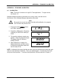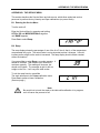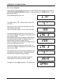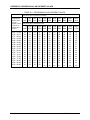
1
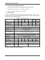
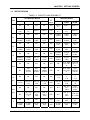
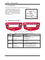
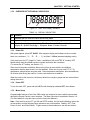
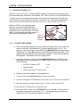
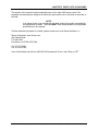
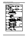
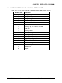
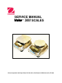
SERVICE MANUAL Valor ™ 3000 SCALES Ohaus Corporation 19A Chapin Road, P.O. Box 2033, Pine Brook, NJ 07058-2033 (973) 377-9000 SERVICE MANUAL Valor ™ 3000 SCALES The information contained in this manual is believed to be accurate at the time of publication, but Ohaus Corporation assumes no liability arising from the use or misuse of this material. Reproduction of this material is strictly prohibited. Material in this manual is subject to change. © Copyright 2009 Ohaus Corporation, all rights reserved. TM Registered trademark of Ohaus Corporation. TABLE OF CONTENTS Page No. CHAPTER 1 GETTING STARTED 1.1 1.2 1.3 1.4 1.5 Introduction ............................................................................................................. 1-1 Service Facilities ..................................................................................................... 1-1 Tools and Test Equipment Required ....................................................................... 1-1 Specifications.......................................................................................................... 1-2 Scale Operation ...................................................................................................... 1-4 1.5.1 Overview of the Controls.................................................................................. 1-4 1.5.2 Overview of the Display Indicators ................................................................... 1-5 1.5.3 Power On......................................................................................................... 1-5 1.5.4 Power Off......................................................................................................... 1-5 1.5.5 Menu Setup ..................................................................................................... 1-5 1.6 Legal For Trade (LFT)............................................................................................. 1-6 1.6.1 LFT Setup Procedure....................................................................................... 1-6 1.7 Menu Structure ....................................................................................................... 1-7 CHAPTER 2 TROUBLESHOOTING 2.1 2.2 Troubleshooting ...................................................................................................... 2-1 Diagnostic Guide..................................................................................................... 2-1 2.2.1 Diagnosis......................................................................................................... 2-1 CHAPTER 3 MAINTENANCE PROCEDURES 3.1 Preventive Maintenance.......................................................................................... 3-1 3.1.1 Preventive Maintenance Checklist ................................................................... 3-1 3.2 Opening the Scale................................................................................................... 3-1 3.2.1 Opening Valor 3000 Standard and Washable Models...................................... 3-2 3.3 Replacing the Load Cell .......................................................................................... 3-3 3.4 Replacing the Printed Circuit Board and Display ..................................................... 3-4 3.5 Replacing the Housing Seals .................................................................................. 3-5 3.6 Replacing the Function Label.................................................................................. 3-6 3.7 Replacing the Plastic Insert..................................................................................... 3-6 CHAPTER 4 TESTING 4.1. Testing .................................................................................................................... 4-1 4.1.1 Test Masses Required ..................................................................................... 4-1 4.2 Operational Test ..................................................................................................... 4-1 4.3 Segment Display Test ............................................................................................. 4-1 4.4. Load Cell Test Using RAMP.................................................................................... 4-1 4.5 Performance Tests.................................................................................................. 4-2 4.5.1 Precision Test .................................................................................................. 4-2 4.5.2 Repeatability Test ............................................................................................ 4-3 4.5.3 Linearity Test ................................................................................................... 4-5 4.5.4 Off-Center Load Test ....................................................................................... 4-5 4.5.5 Adjusting Off Center Load................................................................................ 4-6 CHAPTER 5 DRAWINGS AND PARTS LISTS 5-1 5-2 Valor 3000 Xtreme Scales: Housing & Internal Parts .............................................. 5-2 Valor 3000 Xtreme W Scales: Housing & Internal Parts .......................................... 5-4 Ohaus Corporation www.ohaus.com i Valor™ 3000 Series Service Manual TABLE OF CONTENTS Appendix A STANDARD CALIBRATION Page No. A.1 Calibration............................................................................................................... A-1 Appendix B THE SERVICE MENU B.1 Entering the Service Menu ...................................................................................... B-1 B.2 Ramp ...................................................................................................................... B-1 B.3 Linear Calibration.................................................................................................... B-2 B.4 Span Calibration ..................................................................................................... B-3 B.5 Geographical Adjustment Factor (GEO).................................................................. B-4 B.6 Expanded Readability (E.PAnd) .............................................................................. B-5 APPENDIX C SOFTWARE SERVICE TOOL INSTRUCTIONS C.1 Hardware and Software Setup ................................................................................ C-1 C.2 Configuring the Scale (after replacing the PCB or Load Cell) .................................. C-4 APPENDIX D GEOGRAPHICAL ADJUSTMENT VALUES TABLE D-1. Geographical Adjustment Values.................................................................. D-1 LIST OF TABLES TABLE NO. 1-1 1-2 1-3 1-4 1-5 2-1 4-1 4-2 4-3 4-4 5-1 5-2 D-1. TITLE Page No. Specifications ..................................................................................................... 1-2 Capacity and Readability .................................................................................... 1-3 Functions of Display Controls ............................................................................. 1-4 Display Indicators ............................................................................................... 1-5 Valor 3000 Menu Structure ................................................................................. 1-7 Diagnostic Guide ................................................................................................ 2-2 Calibration Mass Values ..................................................................................... 1-2 Tolerances.......................................................................................................... 4-2 Repeatability Worksheet ..................................................................................... 4-4 Linearity Test Masses......................................................................................... 4-5 Valor 3000 Xtreme Scales: Housing & Internal Parts .......................................... 5-3 Valor 3000 Xtreme W Scales: Housing & Internal Parts...................................... 5-5 Geographical Adjustment Values........................................................................ D-1 LIST OF ILLUSTRATIONS FIGURE NO. 1-1 1-2 1-3 1-4 3-1 3-2 3-3 3-4 3-5 3-6 3-7 3-8 3-9 4-1 4-2 TITLE Power Connection and Seal ............................................................................... 1-4 Valor 3000 Xtreme & Xtreme W Displays ........................................................... 1-4 Valor 3000 Display Indicators ............................................................................. 1-5 LFT/Cal Lock Switch........................................................................................... 1-6 Scale Bottom ...................................................................................................... 3-2 Technique for separating Top and Bottom Housing on Valor 3000 ..................... 3-2 Red lock between battery compartments ............................................................ 3-3 Printed Circuit Board and Display ....................................................................... 3-4 Bottom of Valor 3000 Xtreme W, with Battery Cover on...................................... 3-5 Seal washer for Weighing Plate .......................................................................... 3-5 Seal washer on left-rear of PCB.......................................................................... 3-5 Plastic Insert and Function Label ........................................................................ 3-6 Plastic Insert, viewed from inside Top Housing................................................... 3-6 Segment Display ................................................................................................ 4-1 Scale drawing of Valor 3000 Load Cell and Weighing Pan ................................. 4-6 Valor™ 3000 Series Service Manual ii Ohaus Corporation www.ohaus.com TABLE OF CONTENTS TABLE NO. 5-1 5-2 C-1 C-2 C-3 C-4 C-5 TITLE Page No. Valor 3000 Xtreme Scales: Housing & Internal Parts .......................................... 5-2 Valor 3000 Xtreme W Scales: Housing & Internal Parts...................................... 5-4 RS232 Interface connected to Service Interface, connected to the PCB............. C-1 Service Interface fits into the RS232 Interface .................................................... C-1 Com Port Configuration screen with correct settings........................................... C-2 Config Tool’s Test Command screen.................................................................. C-2 The Config Tool’s Configuration Screen ............................................................. C-3 Ohaus Corporation www.ohaus.com iii Valor™ 3000 Series Service Manual TABLE OF CONTENTS Valor™ 3000 Series Service Manual iv Ohaus Corporation www.ohaus.com CHAPTER 1 GETTING STARTED 1.1 INTRODUCTION This service manual contains the information needed to perform routine maintenance and service on the Ohaus Valor 3000 Series scales. Familiarity with the scale’s Instruction Manual is assumed. The contents of this manual are contained in five chapters: Chapter 1 Getting Started – Contains information on service facilities, tools, specifications, and the mechanical and electronic functions of the scale. Chapter 2 Troubleshooting – Contains a diagnostic guide and error code table. Chapter 3 Maintenance Procedures – Contains preventive maintenance procedures and disassembly, repair and replacement procedures. Chapter 4 Testing – Contains a list of required test masses, an operational test, segment display test, performance tests and adjustments. Chapter 5 Drawings and Parts Lists – Contains exploded views of Valor 3000 scales identifying all serviceable components. Appendix A Standard Calibration – Explains procedures for Standard Calibration, performed prior to using a scale, and after service. Appendix B Service Calibration – Describes the Service Menu and sub-menus, which allow authorized service personnel to perform factory Linearity and Span calibrations (no pre-set limits), take Ramp readings, adjust the GEO Factor, and use E.PAnd to set the readability to 1/10th of the standard readability. Appendix C Software Service Tool Instructions – Used to re-configure the scale after replacing a Printed Circuit Board or Load Cell. Appendix D Geographical Adjustment Values – The chart of scale settings for every geographical latitude away from the equator (in degrees and minutes) and every elevation above sea level (in meters or feet). 1.2 SERVICE FACILITIES To service a scale, the service area should meet the following requirements: • Should be temperature controlled and meet scale specifications for temperature environmental requirements. • Must be free of vibrations such as fork lift trucks close by, large motors, air currents or drafts from air conditioning/heating ducts, open windows, people walking by, fans, etc. • Area must be clean and free of excessive dust. • Work surface must be stable and level. • Scale must not be exposed to direct sunlight or radiating heat sources. • Use an approved Electro-Static Device. Valor™ 3000 Series Service Manual 1-1 Ohaus Corporation www.ohaus.com CHAPTER 1 GETTING STARTED 1.3 TOOLS AND TEST EQUIPMENT REQUIRED 1. Common hand tools are sufficient to disassemble the Valor 3000 scales. 2. RS2323 Interface Connector – PN 71147376 or 72206287 3. Communications Service Interface – PN 72203450 1.4 SPECIFICATIONS Complete specifications for the Ohaus Valor 3000 Scales are listed in Table 1-1. When a scale has been serviced, it must meet the specifications listed in the table. Before servicing the scale, determine what specifications are not met. TABLE 1-1. SPECIFICATIONS V31XH202 V31XH2 V31X3 V31X6 V31XW301 V31XW3/ V31X3N V31XW6/ V31X3N Capacity 200 2000 3000 6000 300 3000 6000 Repeatability (g) 0.01 0.1 1 0.2 1 2 Linearity (g) (+/-) 0.01 0.1 1 0.2 1 2 Model Weighing Units g, kg, lb, oz, lb:oz Application Modes Weigh, Percent weighing, Specific Gravity, Fluid Ounces Tare range To capacity by subtraction ≤3 seconds Stabilization Time 9 VDC 500 mA AC adaptor (supplied) or 4 C (LR14) batteries (not supplied) Power Requirements Calibration Digital with external weight Display Type 6-digit 7-segment LCD with white LED backlight Display Size 15 mm / 0.6” digits Keypad 3-button overlay OIML Class - - - - III III III Ingress Protection - - - - IP65 IP65* IP65* Pan Size (mm / in) 120/4.7 Net Weight (kg / lb) 1.2/2.6 1.3/2.9 1.4/3.1 Shipping Weight (kg/lb) 2.6/5.7 2.7/6 2.8/6.2 146 x 158 / 5.7 x 6.2 * Models V31X3N and V31X6N are not rated IP65. Ohaus Corporation www.ohaus.com 1-2 Valor™ 3000 Series Service Manual CHAPTER 1 GETTING STARTED 1.4 SPECIFICATIONS TABLE 1-2. CAPACITY AND READABILITY Non-Washable Models Units g kg oz Washable Models LFT V31XH202 V31XH2 V31X3 V31X6 SWITCH V31XW301 V31XW3/ V31X3N V31XW6/ V31X6N NA NA NA NA ON 300.0 x 0.2 3000 x 1 6000 x 2 200.00 x 0.01 2000.0 x 0.1 3000 x 1 6000 x 1 OFF 300.0 x 0.1 3000.0 x 0.5 6000 x 1 NA NA NA NA ON 0.3000 x 0.0002 3.000 x 0.001 6.000 x 0.002 0.20000 x 0.00001 2.0000 x 0.0001 3.000 x 0.001 6.000 x 0.001 OFF 0.3000 x 0.0001 3.0000 x 0.0005 6.000 x 0.001 NA NA NA NA ON 10.58 x 0.01 105.80 x 0.05 211.6 x 0.1 7.0550 x 0.0005 70.550 x 0.005 105.80 x 0.05 211.65 x 0.05 OFF 10.585 x 0.005 105.80 x 0.02 211.60 x 0.05 NA NA NA NA ON 0.6615 x 0.0005 6.615 x 0.005 13.225 x 0.005 0.44090 x 0.00005 4.4090 x 0.0005 6.615 x 0.005 13.230 x 0.005 OFF 0.6615 x 0.0005 6.615 x 0.002 13.225 x 0.005 NA NA NA NA ON NA 6 lb : 9.80 oz x 0.05 oz 13 lb: 3.6 oz x 0.1 oz NA 4lb: 6.55oz x 0.01oz 6 lb : 9.80 oz x 0.05oz 13lb: 3.65oz x 0.05oz OFF NA 6 lb : 9.80 oz x 0.02 oz 13 lb: 3.60 oz x 0.05 oz NA NA NA NA ON 10 ½ oz x 1/8 105 ½ oz x 1/8 211 ½ oz x 1/8 7 x 1/8 70½ oz x 1/8 105½ oz x 1/8 211½ oz x 1/8 OFF 10½ oz x 1/8 105½ oz x 1/8 211½ oz x 1/8 NA NA NA NA ON NA 6lb : 9½ oz x 1/8oz 13 lb : 3½ oz x 1/8oz NA 4lb : 6 ½ oz x 1/8 oz 6lb : 9 ½ oz x 1/8oz 13 lb : 3 ½oz x 1/8oz OFF NA 6lb : 9 ½ oz x 1/8oz 13 lb : 3½ oz x 1/8oz NA NA NA NA ON 10.14 x 0.01 101.45 x 0.05 202.9 x 0.1 6.7630 x 0.0005 67.630 x 0.005 101.45 x 0.05 202.90 x 0.05 OFF 10.140 x 0.005 101.44 x 0.02 202.90 x 0.05 lb Lb:oz oz (fra) lb:oz (fra) fl Valor™ 3000 Series Service Manual 1-3 Ohaus Corporation www.ohaus.com CHAPTER 1 GETTING STARTED 1.5 SCALE OPERATION This section contains information on the basic operation of the scale. The included AC adapter may be used to power the scale when battery power is not available. Remove the rubber seal in the bottom. Store it in the location provided. (See Figure 1-1. Connect the AC adaptor plug to the input jack. Seal Input Jack Seal Storage Receptacle Figure 1-1. Power Connection and Seal. 1.5.1 OVERVIEW OF THE CONTROLS Figure 1-2. Valor 3000 Xtreme & Xtreme W Displays. TABLE 1-3. FUNCTIONS OF DISPLAY CONTROLS Button Action Functions O/T On/Off Short Press (when off) Short Press (when on) Turns scale on Sets display to zero Tares weight of item on pan Turns scale off Long Press MODE/UNIT Short Press Long Press Menu Short Press (Menu mode): Steps through active units and modes Enters Menu “No” (toggles through available settings) Short Press Stores 100% reference in % mode Stores reference sample in SG mode Initiates span calibration process “Yes” (selects/accepts displayed setting) ENTER Cal Long Press Short Press (Menu) Ohaus Corporation www.ohaus.com 1-4 Valor™ 3000 Series Service Manual CHAPTER 1 GETTING STARTED 1.5.2 OVERVIEW OF THE DISPLAY INDICATORS 1 3 2 Figure 1-3. Valor 3000 Display Indicators. TABLE 1-4. DISPLAY INDICATORS No. Function 1 Indicates that the measured value has become stable. 2 Standard 7-segment numeric characters, used for displaying weight values. 3 Symbols for weighing modes, include: FL – Fluid Ounces % - Percent (of referenced weight), S – Specific Gravity kg – Kilograms, lb:oz – Pounds & Ounces 1.5.3 Power ON With power applied, press O/T On/Off. After segment display and software revision number, there is a countdown (-4-, -3-, -2-, -1-), and then * 0.00 oz (standard weighing mode). If the scale is set for LFT (Legal For Trade – available on XW and NTEP “N” models), LFT flashes briefly after the software revision number and before the countdown. (To reverse the LFT setting, see Section 1.7.) Allow time for the scale to stabilize after moving it from an area which is at a different temperature than the area where it is to be operated. Allow one hour for each 5°F (2.7°C) temperature change before using the scale. After temperature stabilization, allow an additional 20 minutes after turning the scale on, for the scale electronics to stabilize. When the scale is first turned on, the factory default is to weigh in grams and tare items without setting the menus. 1.5.4 Power OFF To turn the scale OFF, press and hold >O/T< until the display indicates OFF, then release. 1.5.5 Menu Setup Programmable features of the Valor 3000 scales are contained in menus which are accessed through the Display Panel’s control switches. The Menu Structure is described in Section 1.8. (For more detail on using the menus, see the Instruction Manual.) Note: If the scale is set for LFT (on XW and NTEP models), the Unit and Calibration menus are not accessible, and the following Setup submenus are not accessible: Stability, AST, Filter, Power On Unit, and Global Reset. To gain access to these submenus, see the next section. Valor™ 3000 Series Service Manual 1-5 Ohaus Corporation www.ohaus.com CHAPTER 1 GETTING STARTED 1.6 LEGAL FOR TRADE (LFT) When the scale is set for LFT (on XW and NTEP models), the following menu settings cannot be accessed/changed: Calibration, Unit, Stability, AST, Filter, Power On Unit, and Global Reset. To regain access to the locked menu settings, remove the small rectangular LFT/Calibration Lock Switch cover on the bottom of the scale. (See Figure 1-4.) Use a small flathead screw driver to move the CAL switch to the left (closer to the “L” in “CAL”), which turns LFT off. After the LFT/CAL Lock setting has been turned off, the scale must be inspected in accordance with local weights and measures regulations before it can be used in LFT mode again. Local authorities may apply seals on the three screws indicated in Figure 1-4. Screws to which LFT seals may be applied 1.6.1 Figure 1-4. LFT/Cal Lock Switch. LFT SETUP PROCEDURE 4. Set the Geographical Adjustment Factor (GEO) according to the location where the scale is to be used. (See Appendix D. Possible values are from 1 to 31.) The setting is in the Service Menu: press O/T/Off and MODE/UNITMenu simultaneously during power on. Press No three times until GEO appears, then press Yes. Then continuously press No until the desired number appears. Press Yes, then No until END appears. Press Yes to return to weighing mode. 5. Access the Setup menu (Press and hold MODE/UNIT/Menu until SEtUP appears. Press Yes to enter the displayed menu, or No to advance to the next menu, etc.) Set the following: Auto Zero Tracking (AZT) = 0.5d Stability (Stab) =1d Units as per local LFT requirements 6. Perform an accurate calibration. (See Appendix A.) 7. Turn the Scale off and disconnect the AC power connection. 8. Open the rectangular LFT/Calibration Lock Switch Cover on the bottom of the scale. 9. Move the switch to the right (closer to the “C” in “CAL”), which turns LFT on. 10. Reinstall the LFT/Calibration Lock Switch Cover. 11. Reconnect the AC power, press O/T/On/Off to turn on the scale. During power on, the display sequence will now include: “LFT.” This message confirms the proper setting of the LFT mode and the hardware lock switch. Ohaus Corporation www.ohaus.com 1-6 Valor™ 3000 Series Service Manual CHAPTER 1 GETTING STARTED 1.7 Menu Structure Programmable features of the Valor 3000 are contained in menus which are accessed through the Display Panel’s control switches. The menu structure is illustrated below. (For more detail on using the menus, see the Instruction Manual.) TABLE 1-5. VALOR 3000 MENU STRUCTURE SETUP (Press and hold MODE/UNIT/Menu until SETUP appears. Press Yes.) Stability Automatic Zero Tracking (AZT) Filter Backlight Auto Off Power On Unit Global Reset Legal For Trade* End Setup UNIT (appears after pressing Yes to end SETUP menu. Press Yes.) g Kg Oz Lb Lb:Oz FL % S (Specific Gravity) End Units CALIBRATION (Press and hold ENTER/Cal until CAL appears and calibration begins.) See Appendixes A & B for more details. *Legal For Trade is included only in models V31XW301, V31XW3, V31XW6, V31XW3N, and V31XW6N. Valor™ 3000 Series Service Manual 1-7 Ohaus Corporation www.ohaus.com CHAPTER 1 GETTING STARTED Ohaus Corporation www.ohaus.com 1-8 Valor™ 3000 Series Service Manual CHAPTER 2 DIAGNOSTIC GUIDE 2.1 TROUBLESHOOTING This section of the manual contains troubleshooting information. Information is contained to isolate specific problems using Table 2-1, Diagnostic Guide. Follow all directions step by step. Make certain that the work area is clean. Handle scale components with care. Use appropriate Electro-Static Device. 2.2 DIAGNOSTIC GUIDE Table 2-1 is a Diagnostic Guide designed to help locate the problem area quickly and easily. The probable causes are listed with the most common cause first. If the first remedy does not fix the problem, proceed to the next remedy. Before attempting to repair the scale, read all chapters of this manual to be familiar with the scale components and operation. 2.2.1 Diagnosis 1. Isolate and identify the symptom 2. Refer to Table 2-1, Diagnostic Guide and locate the symptom. 3. Follow the suggested remedies in the order they appear. 4. Perform the indicated checks, or see the appropriate section of the manual. 5. Repair or replace the defective section of the scale. NOTE: If more than one symptom is observed, approach one area at a time, and remember that the symptoms may be interrelated. If a problem arises that is not covered in this manual, contact Ohaus Corporation for further information. Valor™ 3000 Series Service Manual 2-1 Ohaus Corporation www.ohaus.com CHAPTER 2 DIAGNOSTIC GUIDE 2.2.1 Diagnosis TABLE 2-1. DIAGNOSTIC GUIDE Symptom Possible Cause Remedy Cannot turn on No power to scale Verify connections and voltage. Poor accuracy Improper calibration Unstable environment Perform calibration • Move scale to suitable location Cannot calibrate Unstable environment Incorrect calibration weight Move the scale to suitable location Use correct calibration weight Cannot access mode Mode not enabled Enter menu and enable mode Cannot access unit Unit not enabled Enter menu and enable unit Err 8.1 Pan has load during power on Remove weight from pan and re-zero. In Service Menu, run RAMP to check Load Cell. Then calibrate. Replace Load Cell. Zero has drifted Load Cell is damaged Err 8.2 Pan was removed prior to power Install pan and re-zero. on In Service Menu, run RAMP to check Zero has shifted Load Cell. Then calibrate. Load Cell is damaged Replace Load Cell. OVER Weight on pan exceeds capacity Remove weight from the pan UNDER Pan was removed during weighing Re-install pan Err 9 New PCB installed. Factory calibration data corrupted Configure scale – see Appendix C. Perform service calibration REF Err Reference Weight is too small Use larger sample LOWrEF Reference Weight is too low for accurate percent weighing. Continue to weigh with less accurate results Menus are locked Scale is set for LFT. out: Cal, Stab, AZT, Filter, Power On Unit or Global Reset Ohaus Corporation www.ohaus.com Turn LFT off. (See Section 1.7.) 2-2 Valor™ 3000 Series Service Manual CHAPTER 3 MAINTENANCE PROCEDURES 3.1 PREVENTIVE MAINTENANCE Ohaus scales are precision instruments and should be carefully handled, stored in a clean, dry, dust-free area, and cleaned periodically. Follow these precautionary steps: – When a scale has had chemicals or liquids spilled on it, all exterior surfaces should be cleaned as soon as possible with warm water on a damp cloth. – Do not leave a mass on the scale when the scale is not in use. – Allow time for the scale to stabilize after moving it from an area which is at a different temperature than the area where it is to be operated. Allow one hour for each 5°F (2.7°C) temperature change before using the scale. After temperature stabilization, allow an additional 20 minutes after turning the scale on, for the scale electronics to stabilize. 3.1.1 Preventive Maintenance Checklist The scale should be inspected and checked regularly, as follows: 1. Remove the Pan and Sub Pan to inspect and clean the area beneath the Pan. 2. Clean the outside of the scale using a damp cloth with warm water. CAUTION DO NOT USE CHEMICAL CLEANERS OR SOLVENTS OF ANY TYPE. SOME CLEANERS ARE ABRASIVE AND MAY AFFECT THE SCALE’S FINISH. 3. Check the Power Cord for broken or damaged insulation. 4. If using batteries and the scale malfunctions, first replace the batteries to see if this resolves the problem. The Valor 3000 takes four “C” (LR 14) batteries. 5. Make a visual inspection for faulty connectors, wiring, and loose hardware. 3.2 OPENING THE SCALE Opening the Valor 3000 scale varies slightly according to the specific model, as detailed below. Use these procedures in order to replace the Load Cell, the Printed Circuit Board and/or LCD Display. Valor™ 3000 Series Service Manual 3-1 Ohaus Corporation www.ohaus.com CHAPTER 3 MAINTENANCE PROCEDURES 3.2.1 Opening Valor 3000 Standard and Washable Models Common hand tools are sufficient to disassemble the Valor 3000 scales. Turn the scale off and unplug the power cord before you begin. 1. Remove the Weighing Pan: pry off the seal tab, remove the screw and washer securing the Pan Support, and lift off the Pan Support. 2. Remove the Load Cell Seal and Ring. (XW models only.) (See Figure 3-1.) Start by lifting the outer edge, then gently lift to pull the O-ring and seal from the center. 3. Remove the screws holding the Housing in place. (See Figure 3-2.) The screw on the left side may have a tamper-evident seal, used in Legal For Trade application. (See Section 1.8 for more details.) Figure 3-1. Proper way to lift off Seal. Screws that secure the Housing (each with a seal washer inside) Note: If separating the Top and Bottom Housing is difficult, because of the seal gasket between them, do not apply pressure to the top of the Load Cell while holding the Housing, to release it from the Bottom Plate. Figure 3-2. Scale Bottom, Valor 3000XW. 4. Replace a screw (without tightening it) in the hole closest to the back end of the scale. Use a thumb-sized coin to press the screw while holding the leveling feet on either side. The Top Housing should come off. (See Figure 3-3.) Ohaus Corporation www.ohaus.com 3-2 Figure 3-3. Technique for separating Top and Bottom Housing on Valor 3000. Valor™ 3000 Series Service Manual CHAPTER 3 MAINTENANCE PROCEDURES 3.3 Replacing the Load Cell The Load Cell may need to be replaced because of scale instability, or because the scale does not calibrate or repeat, or because it is physically broken or displays an error code. 1. Open the scale – see Section 3.2.1. 2. Disconnect the cable connecting the PCB to the Load Cell. – On XW models it is a flat ribbon cable. Gently pry up the collar holding the cable. Use a flat head screwdriver to move the collar to the up position on both sides. The cable will then lift out. – On non-XW models, it is a four-wire cable affixed to the PCB with a white tab pin receptacle. It is easiest to lift out the tab if the PCB is first removed. (See Section 3.4 below.) 3. To release the Load Cell, turn the scale over, holding the Load Cell by hand, and remove the six screws inside the two Battery Compartments. 4. Turn the scale back on its feet and gently lift off the Load Cell. 5. If the Load Cell is malfunctioning, replace it. Unlocked position on red Shipping Lock Up/Down Stop 6. Before installing the replacement Load Cell, check that the red Shipping Lock on the plastic panel between the Battery Compartments is in the unlocked position. 7. Carefully position the Load Cell so the black plastic tab at the rear fits into the brass Up/down Stop, and the screw holes in the steel plate align with their counterparts in the two Battery Compartments. Figure 3-4. Red lock between battery compartments. 8. Turn the scale over. Insert and tighten the screws. 9. When installing the new Load Cell, insert the cable connecting it to the PCB. Reverse the procedure in Step 1 above. 10. To assemble the Housing, follow the steps in Section 3.2.1 in reverse order. 11. Configure the Scale. (See Appendix C.) Note: There is no need to disassemble the Load Cell. It is supplied as an assembled unit. (See Chapter 5 for parts lists.) Valor™ 3000 Series Service Manual 3-3 Ohaus Corporation www.ohaus.com CHAPTER 3 MAINTENANCE PROCEDURES 3.4 Screws holding PCB in place Replacing the Printed Circuit Board and Display 1. Open the scale – see Section 3.2.1. 1. Disconnect the cable from the PCB to the Load Cell. Follow the procedure in Section 3.3. 2. Remove the four screws that hold the PCB in place. Figure 3-5. Printed Circuit Board and Display. 3. Lift the PCB up from the Housing. Insert the replacement PCB. 4. Follow these steps in reverse order to install the new PCB. 5. Turn the scale on. Err 9 will appear. This is normal. 6. Configure the Scale. (See Appendix C.) Note: The PCB and the LCD Display are supplied as a single unit. However, if only the LCD Display needs replacement, it can be separated from the PCB by removing the two screws in the bottom of the PCB, and unsoldering the 24 fine lead-wires connecting it to the PCB. When installing the new LCD Display, carefully feed the lead-wires through their holes, then insert the two screws, and finally solder the 24 lead-wires. Ohaus Corporation www.ohaus.com 3-4 Valor™ 3000 Series Service Manual CHAPTER 3 MAINTENANCE PROCEDURES 3.5 Replacing the Housing Seals Screws securing the LFT switch cover 1. Open scale following instructions in Section 3.2.1. Note the condition of the Load Cell Seal and Ring, which may also need to be replaced. 2. Remove the leveling feet and the two screws that secure the Legal-For-Trade (LFT) switch cover. (See Figure 3-6) 3. Remove the screws holding the Bottom Plate. Then lift off the Bottom Plate. (See Figure 3-6) Tamper-evident screw. Screws holding Bottom Plate Figure 3-6. Bottom of Valor 3000 Xtreme W. 4. Carefully position the Bottom Plate Seal to align with the matching holes on the Bottom Plate. Then mount the Bottom Plate on the Bottom Housing, and insert and tighten the six small screws that hold it. 5. Re-install the leveling feet, and then mount the Bottom Plate Gasket. Figure 3-7. Bottom Plate Gasket and Seal. 6. Turn the scale over and replace the seal washers in the holes of the screws that hold the Top Housing in place. (See Figure 3-2.) 7. There is a seal-washer to the left of the PCB, inserted beneath a screw and steel washer on the left-rear of the PCB. (See Chapter 5 for the Housing Seal Kit.) Figure 3-8. Seal washer on left-rear of PCB. 8. Mount the Top Housing, careful to clear the Bottom Plate Gasket on all sides. Then insert all screws. 6. Install the new seal on the Pan Support. Insert it through the hole shown in Figure 3-9. Figure 3-9. Seal washer for Weighing Plate Valor™ 3000 Series Service Manual 3-5 Ohaus Corporation www.ohaus.com CHAPTER 3 MAINTENANCE PROCEDURES 3.6 Replacing the Function Label The Function Label may need to be replaced. (See Chapter 5 for parts information.) Use a broad blade, such as a wide X-Acto knife, to remove the label. Clean the glue residue from the Housing surface. Then carefully place the new label where the old one was. (See Figure 3-8.) Function Label Plastic Insert Figure 3-8. Plastic Insert and Function Label. 3.7 Replacing the Plastic Insert The Plastic Insert also may need to be replaced. (See Chapter 5 for parts information.) Break the tabs off the inside of the Plastic Insert to remove it. Then place the new Insert where the old one was. (See Figure 3-9.) Tabs on Plastic Insert Figure 3-9. Plastic Insert, viewed from inside Top Housing. Ohaus Corporation www.ohaus.com 3-6 Valor™ 3000 Series Service Manual CHAPTER 4 TESTING 4.1 TESTING Before and after servicing a Valor 3000 scale, an operational test and various performance tests should be made to confirm that the scale meets specifications. Turn the scale on and allow it to warm up for at least one hour before performing these tests. NOTE: Make sure the test area is free from drafts and that the scale rests on a level and vibration-free surface. 4.1.1 TEST MASSES REQUIRED The masses required to test the Ohaus Valor 3000 scales must meet the requirements of ASTM Class 4 or OIML F2 Tolerance. The mass values are listed in Table 4-1. TABLE 4-1. CALIBRATION MASS VALUES MODELS Calibration Weights 4.2 V31XH202 V31XH2 V31X3 V31X6 V31XW301 V31XW3 V31XW6 200g 2 kg 3 kg 6 kg 300 g 3 kg 6 kg Operational Test 1. Connect a functioning Power Adapter to the scale power receptacle located on the bottom of the scale, or install 4 “C” (LR 14) batteries. 2. Plug the Power Cord into a suitable power source. 4.3 Segment Display Test Turn the scale on, and ensure that all segments are enabled and displayed briefly. This is a Segment Display Test. (See Figure 4-1.) Figure 4-1. Segment Display 4.4 Load Cell Test Using RAMP To test the Load Cell using RAMP, see Appendix B. Valor™ 3000 Series Service Manual 4-1 Ohaus Corporation www.ohaus.com CHAPTER 4 TESTING 4.5 Performance Tests Accurate performance of the Valor 3000 scales is determined by a series of four performance tests. The displayed readings are compared with the tolerances listed in Tables 4-2 and 4-3. Tolerance values are expressed in counts. A one-count difference is shown in the last digit on the scale display. TABLE 4-2. TOLERANCES Model Precision V31XH202 V31XH2 V31X3 V31X6 V31XW301 V31XW3/ V31X3N V31XW6/ V31X3N ±1 ±1 ±1 ±1 ±2 ±1 ±2 1 1 1 1 2 1 2 ±1 ±1 ±1 ±1 ±2 ±1 ±2 Repeatability Linearity NOTE: The following performance tests are used to evaluate scale operation before and after repairs. The scale must meet the requirements specified in each test as well as the specifications listed in Table 4-1. Before proceeding with the following tests, the scale should be calibrated. (See Appendix A.) 4.5.1 Precision Test The Precision Test measures the Standard Deviation of a set of similar weight readings, which should match the specification for each model, listed in Tolerance Table 4-2. 1. Power on the balance. The reading on the display should be 0g. 2. Select a mass weighing near the maximum capacity of the balance, and place it on the center of the Pan. Observe and record the reading. 3. Remove the mass. The reading should return to 0g ± the tolerance in Table 4-2. 4. Repeat this test three times. The readings should be within tolerances. If so, the balance passes the Precision Test. 5. If the deviation for any set of readings (using the same mass placed on the center of the Pan) is greater than the tolerance listed in Table 4-2, the balance does not meet the precision specification. Inspect and correct the following areas: – Check for mechanical obstructions. Any foreign object touching any part of the moving assemblies will cause a balance to fail the Precision Test. Inspect and correct as necessary. – If the scale does not meet specifications, move it to a suitable location, ensure that it is level, and try again. If it still does not meet specifications, perform a service calibration, and try again. (See Appendix B for Service Calibration.) – If the scale does not pass this test, the Load Cell may need to be replaced. Ohaus Corporation www.ohaus.com 4-2 Valor™ 3000 Series Service Manual CHAPTER 4 TESTING 4.5.2 Repeatability Test Repeatability is the Standard Deviation of a set of similar weight readings. Requirements: – To perform this test a single mass must be used for all readings. – The test mass should be approximately ½ of the capacity of the instrument. – Wear gloves when handling the mass. Before starting a repeatability test, set up the instrument as follows: Set Up: Enter the menu and adjust and record the following settings: A. Set the Stability setting to its lowest setting. B. Set the Filter level to medium or the center of its range. C. Set the AZT (Auto Zero Tracking) to .5d or its lowest setting. Do not turn it off. D. Set the instrument to display the same units as the performance specifications. (Usually kg, g, or mg) Record Settings: Stability Setting = ____________ Filter Level Setting = ____________ Auto Zero Tracking Setting = ____________ Displayed Units = ____________ Mass Used = ____________ TEST PROCEDURE: 1. Zero the instrument. 2. Using a test mass approximately half the capacity of the instrument, place the mass on the center of platform. Record the reading on the worksheet provided. 3. Remove the mass from the platform. 4. Repeat this test starting at Step 1 until you record a total of ten readings Fill in the worksheet (Table 4-3) with the ten (10) readings. Valor™ 3000 Series Service Manual 4-3 Ohaus Corporation www.ohaus.com CHAPTER 4 TESTING 4.5.2 Repeatability Test TABLE 4-3. REPEATABILITY WORKSHEET n Reading Delta = Reading – Mean Delta x Delta 1 2 3 4 5 6 7 8 9 10 n = number of Reading Mean = Sum of readings / 10 Delta = Reading – Mean Standard Deviation = Square Root of (sum of (Delta x Delta) / 9) 5. Add the ten readings and divide the total by 10 to find the Mean (average). 6. Mean = (Reading 1 + Reading 2 + Reading 3 + Reading 4 + Reading 5 7. + Reading 6 + Reading 7+ Reading 8 + Reading 9 + Reading 10) / 10 Mean =________ 6. Calculate the Delta for each reading and record in the work sheet. Delta = Reading – Mean 7. Calculate the Delta x Delta for each reading and record in worksheet. 8. Add the ten Delta x Delta values and divide by 9 9. Calculate the Standard Deviation by applying the square root of the result from step 8. Standard Deviation =___________ Note: If the balance does not meet specifications, move it to a suitable location, ensure that it is level, and try again. If it still does not meet specifications, perform a service calibration, and try again. (See Appendix B for Service Calibration.) Ohaus Corporation www.ohaus.com 4-4 Valor™ 3000 Series Service Manual CHAPTER 4 TESTING 4.5.3 Linearity Test This test is used to determine the linearity of the unit throughout its operating range. The masses used to perform this test can be utility masses. NOTE: The scale must pass the Precision and Repeatability Tests, and be calibrated before the Linearity Test may be performed. TABLE 4-4. LINEARITY TEST MASSES 200 x 0.01 2000 x 0.1 3000 x 1 6000 x 1 300 x 0.2 IP 3000 x 1 IP 6000 x 2 IP Reference Wt. 50 500 750 1500 75 750 1500 Load 1 50 500 750 1500 75 750 1500 Load 2 100 1000 1500 3000 150 1500 3000 Load 3 150 1500 2250 4500 225 2250 4500 Capacity (g) NOTE: All masses are nominal values. Be certain to use the same reference mass throughout the procedure. 1. Place the test mass on the Scale, record the weight and remove. 2. Place Load 1 on the Scale and press TARE. 3. Place the test mass on the Scale, record the weight and remove. 4. Place Load 2 on the Scale and press TARE. 5. Place the test mass on the Scale, record the weight and remove. 6. Place Load 3 on the Scale and press TARE. 7. Place the test mass on the Scale and record the weight. 8. The difference in the weights of the test mass should be within the tolerance in Table 4-1. If not, calibrate (see Appendix A.1) and repeat the test. 9. If the Scale remains out of tolerance, the Load Cell may need to be replaced. 4.5.4 Off-Center Load Test The Off-Center Load Test is used to determine whether displayed weight values are affected by moving the sample to different areas of the Pan. 1. Place half of the scale’s capacity in the center of the Pan. 2. Note the reading. 3. Move the mass halfway (between the center and the edge) to the front of the Pan. Note any differences in the displayed weight reading. 4. Repeat the test for the back, left, and right position of the Pan. 5. Maximum allowable change in displayed weight readings for each of the four positions can be found in Specifications Tables (Chapter 1). If this maximum is exceeded, follow procedures in Section 4.5.5, Adjusting Off Center Load. Valor™ 3000 Series Service Manual 4-5 Ohaus Corporation www.ohaus.com CHAPTER 4 TESTING 4.5.5 Adjusting Off Center Load If the Off Center Load (OCL) is excessive, perform adjustment as follows: Top view of Load Cell Side view of Load Cell 2 3 1 4 Weighing Pan’s center, with points A – D indicated Figure 4-2. Scale drawing of Valor 3000 Load Cell and Weighing Pan. 1. Place the test weight in the center of the Weighing Pan. 2. Tare the balance. 3. Move the weight to point A and record the reading. 4. Move the weight to point B and record the reading. 5. Move the weight to point C and record the reading. 6. Move the weight to point D and record the reading. 7. If the reading at point A is negative, file at points 1 and 4 AT AN ANGLE. 8. If the reading at point B is negative, file at points 1 and 2 STRAIGHT ACROSS. 9. If the reading at point C is negative, file at points 2 and 3 AT AN ANGLE. 10. If the reading at point D is negative, file at points 3 and 4 STRAIGHT ACROSS. Note: It is not recommended that you try to adjust more than –5 counts if the beam has been filed already. If the beam has not been filed previously, you can adjust –10 counts. Remember, when filing you are weakening the beam. File a little at a time. Ohaus Corporation www.ohaus.com 4-6 Valor™ 3000 Series Service Manual CHAPTER 5 PARTS LISTS & DIAGRAMS This section of the manual contains exploded views for the Valor 3000 series scales. The exploded view drawings are designed to identify the parts which can be serviced on the scale in the field. NOTE: In all cases where a part is replaced, the scale must be thoroughly checked after the replacement is made. The scale MUST meet the parameters of all applicable specifications in this manual. If further technical information is needed, please contact your local Ohaus distributor, or: Ohaus Corporation, www.ohaus.com 19A Chapin Road P.O. Box 2033 Pine Brook, NJ 07058-2033 USA Tel: 973-377-9000 Fax: 973-593-0359 In the United States call toll free, 800-526-0659 between 8:00 a.m. and 6:00 p.m. EST. Valor™ 3000 Series Service Manual 5-1 Ohaus Corporation www.ohaus.com CHAPTER 5 PARTS LISTS & DIAGRAMS 5.1 VALOR 3000 XTREME SCALES: HOUSING & INTERNAL PARTS 1a 1b 16 8 2a 2b 3 4 5 6 16 14 13 7 15 8 80 8 10 12 16 11 Figure 5-1. Valor 3000 Xtreme Scales: Housing & Internal Parts. Ohaus Corporation www.ohaus.com 5-2 Valor™ 3000 Series Service Manual CHAPTER 5 PARTS LISTS & DIAGRAMS 5.1 VALOR 3000 XTREME SCALES: HOUSING & INTERNAL PARTS TABLE 5-1. VALOR 3000 XTREME SCALES: HOUSING & INTERNAL PARTS Drawing Item Description 1a Pan, Square, 146mm x 158mm 2a Pan Support Square 1b Pan, Round, 120mm 2b Pan Support Round 3 Plastic insert Non-IP 4 Function Label, without Level 5 Housing, Top, Ex IP Model, No Labels 6 Load Cell 7 Housing, Bottom 8 Seal Kit, Housing 10 Housing, Bottom Plate, No LFT 11 Feet, 4, Adjustable 12 Battery Cover, Seal and Screws 13 PCB, Main, Low Resolution 14 LCD with Backlight 15 Seal, AC Adapter 16 Hardware Kit 80 Adapter Valor™ 3000 Series Service Manual 5-3 Ohaus Corporation www.ohaus.com CHAPTER 5 PARTS LISTS & DIAGRAMS 5.2 VALOR 3000 XTREME W SCALES: HOUSING & INTERNAL PARTS Figure 5-5. Valor 3000 Xtreme W Scales: Housing & Internal Parts. Ohaus Corporation www.ohaus.com 5-4 Valor™ 3000 Series Service Manual CHAPTER 5 PARTS LISTS & DIAGRAMS 5.2 VALOR 3000 XTREME W SCALES: HOUSING & INTERNAL PARTS TABLE 5-5. VALOR 3000 XTREME W SCALES: HOUSING & INTERNAL PARTS Drawing Item Description 1 Pan, Square, 146mm x 158mm 2 Pan Support Square 3 Load Cell Seal Kit, IP Models 4 Function Label, Level 5 Housing, Top, IP Models, No Labels 6 Load Cell, 6000g 7 Housing, Bottom 8 Seal Kit, Housing 10 Housing, Bottom Plate, LFT 11 Feet, 4, Adjustable 12 Battery Cover, Seal and Screws 13 PCB, Main, OIML 14 LCD with Backlight 15 Seal, AC Adapter 16 Hardware Kit 17 Seal Kit, LFT 18 Level, Bubble 80 Adapter, US, 120V Valor™ 3000 Series Service Manual 5-5 Ohaus Corporation www.ohaus.com CHAPTER 5 PARTS LISTS & DIAGRAMS Ohaus Corporation www.ohaus.com 5-6 Valor™ 3000 Series Service Manual APPENDIX A STANDARD CALIBRATION APPENDIX A. STANDARD CALIBRATION A.1 CALIBRATION Note: This menu is locked out in Legal For Trade applications. To regain access, see Section 1.6. Standard calibration should be performed prior to using a scale, and after service. See Section 4.2 for Calibration Masses required for each model. Note: Be careful not to touch the scale or the table while calibration is in progress, as it will cause the process to fail. 1. Press and hold the ENTER/Cal button until .C.A.L. appears. 2. Press Yes. CAL appears, followed by a flashing -C- while a zero reading is stored. 3. The specified calibration weight value appears. Place the weight on the pan. The display shows -C- while the reading is stored. 4. When calibration is complete, the display shows done, and then returns to the previous application mode and scale is ready for use. .C.a.l. -C6000 Done NOTE: If calibration fails, ensure that the test area is free from drafts and the surface the scale rests on is level and free of vibrations. Then try to calibrate again. If it continues to fail, there may be an internal problem. To resolve internal problems, follow procedures in Chapter 3. Valor™ 3000 Series Service Manual A-1 Ohaus Corporation www.ohaus.com APPENDIX A STANDARD CALIBRATION Ohaus Corporation www.ohaus.com A-2 Valor™ 3000 Series Service Manual APPENDIX B THE SERVICE MENU APPENDIX B. THE SERVICE MENU This section describes the Service Menu and sub-menus, which allow authorized service personnel to perform factory Linearity and Span calibrations (no pre-set limits). B.1 Entering the Service Menu Turn the scale off. Enter the Service Menu by pressing and holding O/T/On/ Off and MODE/UNIT/Menu together until RAMP appears. Press Yes to select Ramp. B.2 Ramp ramMp The ramp display shows the percentage of use of the A to D circuit, that is, of the temperaturecompensated duty cycle. The actual value is not as important as how it changes. It should increase as the weight on the scale is increased. The ramp display should remain constant without fluctuations. If you press Yes to select Ramp, a number appears. It should be constant. Add masses from minimum to maximum capacity. The reading will increase, but should not fluctuate. The example at right is with no weight on the Pan. It will vary with other scales. To exit the ramp function, press No. The scale advances to the Linear calibration menu. Press Yes to perform Linear Calibration. (See next page.) 39 LIN Note: Be careful not to touch the scale or the table while calibration is in progress, as it will cause the process to fail. Valor™ 3000 Series Service Manual B-1 Ohaus Corporation www.ohaus.com APPENDIX B THE SERVICE MENU B.3 Linear Calibration Linear calibration automatically follows Ramp. To start from the Service Menu, press and hold O/T/On/Off and MODE/UNIT/Menu together. As the scale powers up, RAMP appears. Press No to bypass Ramp. When Linear appears, press Yes. The display shows zero value. -C- while the scale acquires the After the zero value is acquired, the display shows the first calibration point value. Place the indicated weight on the Pan, and press Yes. If the target weight is not placed on the pan within 10 seconds, error CAL E is displayed for 3 seconds and the menu returns to LIN. Pressing Yes after placing the prompted weight accepts the linearity mid-point weight .The display shows -Cwhile the scale acquires the weight reading. After the mid-point value is acquired, the display shows the second calibration point value. If the target weight is not placed on the pan within 10 seconds, error CAL E is displayed for 3 seconds and the menu returns to LIN. Pressing Yes after placing the prompted weight accepts the linearity full-capacity weight. The display shows -Cwhile the scale acquires the weight reading. After the full-capacity value is acquired, the display shows done for 2 seconds and returns to LIN. Press No to move to Span calibration. Then press Yes. Ohaus Corporation www.ohaus.com B-2 LIN -C100 Cal E 200 Cal E -CDone Span Valor™ 3000 Series Service Manual APPENDIX B THE SERVICE MENU B.4 Span Calibration Span calibration from the service menu allows you to set a new zero and maximum setting. This is distinct from user level span calibration, which allows a user to adjust the zero and maximum setting within the range established by the service menu span setting. Span calibration automatically follows Linear calibration. To start from the Service Menu, press and hold O/T/On/Off and MODE/UNIT/Menu together. As the scale powers up, RAMP appears. Press No to bypass Ramp. Lin appears. Press No. SPAN appears. Press Yes. The display shows zero value. -C- while the scale acquires the The specified maximum mass weight flashes. Place the indicated weight in the center of the Pan. If the target weight is not placed on the pan within 10 seconds, error CAL E appears for 3 seconds and the menu returns to SPAN. Start again. Pressing Yes after placing the prompted weight accepts the span weight shown on the display. The display then shows -C- while the scale acquires the span value. After the span value is acquired, the display shows done for 2 seconds and returns to SPAN. Press No to advance to the next option (Geo). (To exit the Service Menu, press No until End appears. Then press Yes.) SPAn -C200 Cal e -Cdone NOTE: If calibration fails, ensure that the test area is free from drafts and the surface the scale rests on is level and free of vibrations. Then try to calibrate again. If it continues to fail, there may be an internal problem. To resolve internal problems, follow procedures in Chapter 3. Valor™ 3000 Series Service Manual B-3 Ohaus Corporation www.ohaus.com APPENDIX B THE SERVICE MENU B.5 Geographical Adjustment Factor (GEO) The Geo Factor adjustment allows entry of values from 0 to 31 and is used to compensate for slight variations in gravity at different geographical locations around the world. This feature allows authorized personnel to accurately calibrate the scale at a location other than the location where the scale is to be used. Prior to calibration, the Geo Factor is set to correspond to the geographical location where the calibration is being performed. Following calibration, the Geo Factor is changed to match the location where the scale is to be used. If required, the scale may also be sealed according to the required approval regulations. NOTE Only an authorized manufacturer’s representative or certified verification personnel should make these changes. Changing the Geo Factor alters the calibration values. In the Service Menu, press No when the display reads SPAN. GEO appears. Press Yes to edit the GEO setting. The current setting is the first to be shown. NOTE: Factory setting for GEO is 13 in general and 19 for Europe Press No until the desired setting appears. Values from 1 to 31 are available. See Appendix D to determine the correct value. Press Yes to accept the value shown on the display. The menu returns to GEO Ohaus Corporation www.ohaus.com B-4 SEt 19 GeO Valor™ 3000 Series Service Manual APPENDIX B THE SERVICE MENU B.6 Expanded Readability (E.PAnd) E.PAnd sets the readability to 1/10th of the standard readability. (That is, if standard readability is .01, with E.PAND on it would be .001.) Normally E.PAND is off. Once it is set on, it will be on until the scale is switched off. When the scale is switched off E.PAnd is automatically set to off. In the Service Menu, press No when the display reads GEO. E.PAND appears. Press Yes to enter the E.PAND setting menu. E.PAND appears again. Press Yes to turn it on. ON appears. Pressing Yes again accepts the setting. Pressing No causes OFF to appear. In either case, E.PAND appears again. Press Yes to change the setting. To accept a chosen setting (either ON or OFF) press No when E.PAND appears. End appears. If you selected ON to activate E.PAND mode, the scale will remain in high resolution (readability) until it is turned off. E.PAND End When the scale is switched off E.PAnd is automatically set to off. Valor™ 3000 Series Service Manual B-5 Ohaus Corporation www.ohaus.com APPENDIX B THE SERVICE MENU Ohaus Corporation www.ohaus.com B-6 Valor™ 3000 Series Service Manual APPENDIX C SOFTWARE SERVICE TOOL INSTRUCTIONS APPENDIX C. SOFTWARE SERVICE TOOL INSTRUCTIONS The Software Service Tool (Part Number 80252509) is required when either a main PC Board or a Load Cell is replaced in a Valor 3000 scale. It is used to re-configure the scale to its original parameters in the case of a PCB replacement, or new parameters in the case of a Load Cell replacement. C.1 Hardware and Software Setup 1. First, check that the scale’s A-Off feature, under the SETUP menu, is set to OFF. If this setting is left ON, the scale will shut off during configuration. 2. To connect the scale to a personal computer, use the hardware interface: (See Figures C-1 and C-2.) – RS232 Interface and Cable (PN 71147376 or 72206287) – A Communications Service Interface (PN 72203450) that attaches to the RS232 Interface 3. Plug the cable into the PC’s RS232 port. Figure C-2. Service Interface fits into the RS232 Interface with the gap on the left side when the label side is up on the RS232 Interface. Figure C-1. RS232 Interface connected to Service Interface, connected to the scale’s PCB, circuit board side up. 4. Install the software on a Personal Computer running Microsoft Windows NT 4.0 or later, or Microsoft Windows 98 or later. 5. Run the program Service Tool. (See next page.) Valor™ 3000 Series Service Manual C-1 Ohaus Corporation www.ohaus.com APPENDIX C SOFTWARE SERVICE TOOL INSTRUCTIONS C.1 Hardware and Software Setup continued 6. Open Configtool.exe and click Check Scale. Figure C-3. First screen of Configtool.exe. 7. Click COM port for Communication setup. Figure C-4. Com Port Configuration screen with correct settings. 8. The communications parameters should appear mid-screen. Correct values are: Baud = 2400 ByteSize = 7 Parity = None If the settings do not match, click the arrow next to the parameter and select the correct value. (See Figure C-4.) Ohaus Corporation www.ohaus.com C-2 Valor™ 3000 Series Service Manual APPENDIX C SOFTWARE SERVICE TOOL INSTRUCTIONS C.1 Hardware and Software Setup continued 9. Click the Test Command tab to test the communications. (See Figure C-4.) Figure C-5. Config Tool’s Test Command screen. – – Enter a “P” command. The scale should respond with a weight value (e.g., 0.02g). Enter a “V” command. The response should be the software version (e.g., Sr: 1.03). Valor™ 3000 Series Service Manual C-3 Ohaus Corporation www.ohaus.com APPENDIX C SOFTWARE SERVICE TOOL INSTRUCTIONS C.2 Configuring the Scale (after replacing the PCB or Load Cell) 1. When communications are reliable, return to the Config tab. Press the Read button (E) and the data will be read from the scale. 2. If the PC Board has been replaced, the scale needs to be configured. To configure the scale, enter its serial number in the blank (C), then click Scale in the Serial Number box (A), and click OK (D). When the OK button highlights again, click Update (F). Turn the scale off and then back on to save the data. A B C D G F Figure C-6. The Config Tool’s Configuration Screen. E 3. If the Load Cell was replaced, follow the same procedure as above, but enter the Load Cell serial number, and click Load Cell (B) in the Serial Number box. 4. The bar (G) is a graphical measure of the Load Cell output currently being used. 5. Turn the scale off, perform a Service Calibration (see Appendix B), followed by Operational and Performance tests (Chapter 4). Ohaus Corporation www.ohaus.com C-4 Valor™ 3000 Series Service Manual APPENDIX D GEOGRAPHICAL ADJUSTMENT VALUES APPENDIX D. GEOGRAPHICAL ADJUSTMENT VALUES TABLE D-1. GEOGRAPHICAL ADJUSTMENT VALUES. Elevation above sea level in meters Geographical latitude away from the equator (North or South), in degrees and minutes. 0°00′ - 5°46′ 5°46′ - 9°52′ 9°52′ - 12°44′ 12°44′ - 15°06 15°06′ - 17°10′ 17°10′ - 19°02′ 19°02′ - 20°45′ 20°45′ - 22°22′ 22°22′ - 23°54′ 23°54′ - 25°21′ 25°21′ - 26°45′ 26°45′ - 28°06′ 28°06′ - 29°25′ 29°25′ - 30°41′ 30°41′ - 31°56′ 31°56′ - 33°09′ 33°09′ - 34°21′ 34°21′ - 35°31′ 35°31′ - 36°41′ 36°41′ - 37°50′ 37°50′ - 38°58′ 38°58′ - 40°05′ 40°05′ - 41°12′ 41°12′ - 42°19′ 42°19′ - 43°26′ 43°26′ - 44°32′ 44°32′ - 45°38′ 45°38′ - 46°45′ 46°45′ - 47°51′ 47°51′ - 48°58′ 48°58′ - 50°06′ 50°06′ - 51°13′ 51°13′ - 52°22′ 52°22′ - 53°31′ 53°31′ - 54°41′ 54°41′ - 55°52′ 000 325 325 650 650 975 0975 1300 1300 1625 1625 1950 1950 2275 2275 2600 2600 2925 2925 3250 3250 3575 Elevation above sea level in feet 0000 1060 1060 2130 2130 3200 3200 4260 4260 5330 5330 6400 6400 7460 7460 8530 8530 9600 09600 10660 10660 11730 05 05 06 06 07 07 08 08 09 09 10 10 11 11 12 12 13 13 14 14 15 15 16 16 17 17 18 18 19 19 20 20 21 21 22 22 04 05 05 06 06 07 07 08 08 09 09 10 10 11 11 12 12 13 13 14 14 15 15 16 16 17 17 18 18 19 19 20 20 21 21 22 04 04 05 05 06 06 07 07 08 08 09 09 10 10 11 11 12 12 13 13 14 14 15 15 16 16 17 17 18 18 19 19 20 20 21 21 03 04 04 05 05 06 06 07 07 08 08 09 09 10 10 11 11 12 12 13 13 14 14 15 15 16 16 17 17 18 18 19 19 20 20 21 03 03 04 04 05 05 06 06 07 07 08 08 09 09 10 10 11 11 12 12 13 13 14 14 15 15 16 16 17 17 18 18 19 19 20 20 02 03 03 04 04 05 05 06 06 07 07 08 08 09 09 10 10 11 11 12 12 13 13 14 14 15 15 16 16 17 17 18 18 19 19 20 02 02 03 03 04 04 05 05 06 06 07 07 08 08 09 09 10 10 11 11 12 12 13 13 14 14 15 15 16 16 17 17 18 18 19 19 01 02 02 03 03 04 04 05 05 06 06 07 07 08 08 09 09 10 10 11 11 12 12 13 13 14 14 15 15 16 16 17 17 18 18 19 01 01 02 02 03 03 04 04 05 05 06 06 07 07 08 08 09 09 10 10 11 11 12 12 13 13 14 14 15 15 16 16 17 17 18 18 00 01 01 02 02 03 03 04 04 05 05 06 06 07 07 08 08 09 09 10 10 11 11 12 12 13 13 14 14 15 15 16 16 17 17 18 00 00 01 01 02 02 03 03 04 04 05 05 06 06 07 07 08 08 09 09 10 10 11 11 12 12 13 13 14 14 15 15 16 16 17 17 Valor™ 3000 Service Manual D-1 Ohaus Corporation www.ohaus.com APPENDIX D GEOGRAPHICAL ADJUSTMENT VALUES TABLE D-1. GEOGRAPHICAL ADJUSTMENT VALUES. Elevation above sea level in meters Geographical latitude away from the equator (North or South), in degrees and minutes. 55°52′ - 57°04′ 57°04′ - 58°17′ 58°17′ - 59°32′ 59°32′ - 60°49′ 60°49′ - 62°09′ 62°09′ - 63°30′ 63°30′ - 64°55′ 64°55′ - 66°24′ 66°24′ - 67°57′ 67°57′ - 69°35′ 69°35′ - 71°21′ 71°21′ - 73°16′ 73°16′ - 75°24′ 75°24′ - 77°52′ 77°52′ - 80°56′ 80°56′ - 85°45′ 85°45′ - 90°00′ 000 325 325 650 650 975 0975 1300 1300 1625 1625 1950 1950 2275 2275 2600 2600 2925 2925 3250 3250 3575 Elevation above sea level in feet 0000 1060 1060 2130 2130 3200 3200 4260 4260 5330 5330 6400 6400 7460 7460 8530 8530 9600 09600 10660 10660 11730 23 23 24 24 25 25 26 26 27 27 28 28 29 29 30 30 31 22 23 23 24 24 25 25 26 26 27 27 28 28 29 29 30 30 22 22 23 23 24 24 25 25 26 26 27 27 28 28 29 29 30 21 22 22 23 23 24 24 25 25 26 26 27 27 28 28 29 29 21 21 22 22 23 23 24 24 25 25 26 26 27 27 28 28 20 21 21 22 22 23 23 24 24 25 25 26 26 27 27 28 20 20 21 21 22 22 23 23 24 24 25 25 26 26 27 27 19 20 20 21 21 22 22 23 23 24 24 25 25 26 26 27 19 19 20 20 21 21 22 22 23 23 24 24 25 25 26 26 18 19 19 20 20 21 21 22 22 23 23 24 24 25 25 26 18 18 19 19 20 20 21 21 22 22 23 23 24 24 25 25 29 28 28 27 27 26 26 Ohaus Corporation www.ohaus.com D-2 Valor™ 3000 Service Manual *80252591* P/N 80152591 SERVICE MANUAL: Valor 3000 SERIES SCALES