1
ASD:Suite User Manual
●
Home
●
Product
●
Technology
●
Resources
ASD:Suite User Manual
ASD:Suite Release 3 v8.3.0
TABLE OF CONTENTS
●
●
●
●
●
The ASD:Suite software design platform
ASD Concepts
❍ Components
❍ Models
❍ Sequence Based Specifications
❍ The ASD:Triangle and Correctness
❍ Operational semantics
■ Operational semantics of rule cases
■ Client requests
■ Notification interfaces
■ ASD Timers and the Timer Cancel Guarantee
❍ State types in a design model
The User Interface
❍ Tabs, Panes and "dockable" Windows
■ Panes and "dockable" windows
■ The Start Page
■ The "Model Explorer" in detail
■ Meaning of colours in the SBS tab
■ The context information field in the SBS tab
❍ Menus
■ File
■ Edit
■ View
■ Filters
■ Verification
■ Tools
■ Help
❍ Toolbars
■ The main toolbar
■ The "debugging" toolbar
■ The state diagram viewer toolbar
❍ Status bar
Basic Modelling
❍ Build ASD components
❍ Create ASD models
■ Create interface models
■ Create application interfaces
■ Specify events for application interfaces
■ Create notification interfaces
■ Specify events for notification interfaces
■ Create modelling interfaces
■ Specify events for modelling interfaces
■ Create design models
❍ Create Tags
❍ Specify used services
■ Specify primary references
■ Specify used interfaces
■ Specify secondary references
■ Remove references
❍ Specify behaviour
■ Specify state variables
■ Specify state information
■ Specify actions
■ Specify target state
■ Specify comments
■ Specify tags
■ Specify guards
■ Specify state variable updates
■ Specify non-deterministic behaviour
■ Add or delete a rule case
■ Insert or replace rule cases
■ Duplicate a state
❍ Define and use parameters
■ Parameter declaration
■ Example of (simple) parameter passing
■ Changing the number of parameters
■ Renaming the parameter in the trigger of a rule case
■ Specifying arguments for an action
■ Parameter storage
❍ Load and close ASD models
❍ Upgrade ASD models
❍ Find and Replace
❍ Filter data
■ Definitions for "filter" and "rule case attributes"
■ Selection and application of filters
■ Editing the custom filter
❍ Generate, Print, or Export state diagrams
❍ Save ASD models
❍ Print ASD models
Advanced Modelling
❍ Add sub machines
❍ Specify state invariants
❍ Specify behaviour using used service reference state variables
❍ Specify construction parameters
■ Pass parameters
http://community.verum.com/documentation/user_manual_pdf.aspx/8.3.0/toc (1 of 2) [16/08/2012 11:20:04]
●
Training
●
Purchase
●
Company
ASD:Suite User Manual
Pass an instance of a used component
Pass a vector of instances
■ Pass a shared instance
■ Pass a primary reference
❍ Save As
❍ Create an ASD model from an existing one
❍ Reassign interface model dependencies in a design model
❍ Specify publishers and observers
❍ Use singleton events to restrict notification events
❍ Use yoking threshold to restrict notification events
❍ Serialise ASD components
❍ Ignore warning dialogs
Check conflicts
■
■
●
●
●
●
●
●
●
●
Fix conflicts
❍ Fix reconcile conflicts
❍ Fix syntax related conflicts
❍ Fix name duplicates
❍ Fix interface related conflicts
❍ Fix argument, parameter or component variable related conflicts
❍ Fix used service references related conflicts
❍ Fix rule case related conflicts
❍ Fix state variable and guard related conflicts
Verify an ASD model
Prepare the ASD model for code generation
❍ Specify component type
❍ Specify execution model
❍ Specify target language and code generator version
❍ Define construction parameters
❍ Specify output path and attribute code with tracing information
❍ Ensure correct referencing of user defined types
❍ Specify path to user provided text for code customization
Generate code from an ASD model
Generate stub code from an ASD interface model
Download the ASD:Runtime
Use the ASD:Suite from the command prompt
❍ Access ASD:Suite features using the ASD:Commandline Client
❍ Upgrade ASD models using the ASD:Converter
© 2012 Verum Software Technologies B.V. All rights reserved
Terms of use | Privacy Policy
http://community.verum.com/documentation/user_manual_pdf.aspx/8.3.0/toc (2 of 2) [16/08/2012 11:20:04]
ASD:Suite User Manual
●
Home
●
Product
●
Technology
●
Resources
●
Training
●
Purchase
●
Company
The ASD:Suite software design platform
User Manual
ASD:Suite Release 3 v8.3.0
The ASD:Suite is a software design (CAD) platform based upon Verum's patented Analytical Software Design (ASD) technology. ASD
makes it possible to create systems from mathematically verified components.
The ASD:Suite is used to define and (automatically) verify models, and to (automatically) generate fully executable source code from
these models. The models specify both structure and behaviour of services, and of components that implement and use these services.
For more details see the ASD Concepts section.
See "How to set up the ASD:Suite" for guidelines about installing and setting up the ASD:Suite.
Note: Starting with the ASD:Suite Release 3 v7.2.0 you have the possibility to install the ASD:Compare, a feature that allows you to find
and eliminate differences between two versions of an ASD model or between two related or unrelated ASD models.
The following list contains the parts of the ASD:Suite installed in the folder specified during installation:
●
●
●
The Windows client - the "ASD ModelBuilder.exe" file
The command prompt client - the ASD:Commandline Client - the "asdc.exe" file
Note: For details see "Access ASD:Suite features using the ASD:Commandline Client".
The ASD:Compare (if selected) - a desktop application: "CompareGui.exe" and a command-line application: "Compare.exe"
Note: For details see "The ASD:Compare User Guide"
In addition to the above, the following is also available:
●
The ASD:Suite Release Notes (see archive for latest and older versions).
●
The ASD:Runtime Guide (see archive for latest and older versions).
●
The ASD:Suite Visual Verification Guide (see archive for latest and older versions).
●
The ASD:Suite Keyboard Shortcuts (see archive for latest and older versions).
●
The ASD:Suite User Manual (see archive for latest and older versions).
A set of interface models and design models together with the related source code describing a simple Alarm system can be
downloaded from here. This is a fully executable system that can be built using Visual Studio (for C++ and C#) and Eclipse (for Java). The
following list contains the names of the design models, together with a brief explanation:
●
AlarmSystem.dm - a model with the simple error, to help in demonstrating the use of visual verification for error tracing.
●
AlarmSystem_corrected.dm - the fully verified, i.e. correct and complete, Alarm system
●
AlarmSystem_original.dm - a copy of the "AlarmSystem.dm". This can be used in case you have changed the "AlarmSystem.dm"
model and want to revert to the original example that includes the error.
To uninstall the ASD:Suite Release <release_number> v<version_number> use the "Start->All Programs->ASD Suite Release
<release_number> V<version_number>->Uninstall" item.
Copyright (c) 2008 - 2012 Verum Software Technologies B.V.
ASD is licensed under EU Patent 1749264 and Hong Kong Patent HK1104100
All rights are reserved. No part of this publication may be reproduced in any form or by any means, electronic, mechanical,
photocopying, recording, or otherwise, without the prior written permission of the copyright owner.
http://community.verum.com/documentation/user_manual_pdf.aspx/8.3.0/overview (1 of 2) [16/08/2012 11:20:08]
ASD:Suite User Manual
© 2012 Verum Software Technologies B.V. All rights reserved
Terms of use | Privacy Policy
http://community.verum.com/documentation/user_manual_pdf.aspx/8.3.0/overview (2 of 2) [16/08/2012 11:20:08]
ASD:Suite User Manual
●
Home
●
Product
●
Technology
●
Resources
●
Training
●
Purchase
●
Company
ASD concepts
Components
ASD is a component-based technology in which systems are composed of a mixture of ASD components and Foreign components.
Within ASD, a component is a common unit of architectural decomposition, specification, design, mathematical verification, code
generation and runtime execution.
ASD components
ASD components are software components that are specified and designed using ASD. An interface model specifies the externally
visible behaviour of a component. A design model specifies its inner working and how it interacts with other components. All ASD
Components must have both an interface model and a design model.
ASD components are mathematically verified. In the ASD:Suite this is done using a Software as a Service (SaaS) application. The
necessary mathematical models are generated automatically from both design and interface models. The source code to implement
an ASD component is generated automatically from its design model.
Foreign components
Foreign components are hardware or software components of a system which are not developed using ASD. As they have to be used
by ASD Components, they must correctly interface and interact with them. They may be third party components, legacy code or
handwritten components representing those parts of a system that cannot be generated from ASD designs. All used foreign
components must have an interface model which specifies the externally visible behaviour of the foreign component. Foreign
components do not have a corresponding design model.
The interface model of foreign components is used for two purposes:
1. For verifying ASD components that use these foreign components: formal models are generated automatically from the
interface models. They are used to verify that an ASD component interacts correctly at runtime with the corresponding
foreign component.
2. For code generation: to generate the correct interface header files.
Note: The handwritten implementation provided for the foreign component must correctly implement all methods declared in the
generated interface header files. This includes ASD specific methods like GetInstance, ReleaseInstance, GetAPI, and RegisterCB.
© 2012 Verum Software Technologies B.V. All rights reserved
Terms of use | Privacy Policy
http://community.verum.com/documentation/user_manual_pdf.aspx/8.3.0/concepts/components [16/08/2012 11:20:11]
ASD:Suite User Manual
●
Home
●
Product
●
Technology
●
Resources
●
Training
●
Purchase
●
Company
Models
ASD supports two types of models:
●
Interface Model
●
Design Model
Interface Model
An interface model is a model of the externally visible behaviour of an ASD component or Foreign component, i.e. the service that
the component implements.
●
It identifies the component's application interfaces and notification interfaces and specifies their associated events.
●
It specifies the externally visible behavioural semantics of the component in the form of one Sequence-Based Specification.
●
●
●
It may also specify modelling interfaces with associated events that are hidden from the client and are used to represent hidden
internal behaviour of the implementation.
The triggers in an interface model are occurrences of:
❍ Call events on application interfaces;
❍ Events on modelling interfaces.
The actions in an interface model are occurrences of:
❍ Reply events on application interfaces;
❍ Events on notification interfaces.
Design Model
A design model is a model of the internal behaviour of an ASD component.
●
●
●
●
●
Its implemented service and used services are specified by interface models;
It fully and deterministically specifies the internal logic of the component as one or more Sequence-Based Specifications;
❍ A simple design is represented by a single Sequence-Based Specification;
❍ A complex design is partitioned hierarchically into a main machine and one or more sub machines. Each of these is specified by a
Sequence-Based Specification.
If the design is partitioned:
❍ There is one transfer interface defined for each sub machine through which the main machine and sub machine communicate.
❍ Transfer interfaces are not visible to clients or servers.
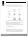
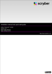
The triggers in a design model are occurrences of:
❍ Call events on application interfaces of the implemented service;
❍ Reply events on the application interfaces of the used services;
❍ Events on the notification interfaces of the used services;
❍ For a main machine, reply events on transfer interfaces;
❍ For a sub machine, call events on its transfer interface.
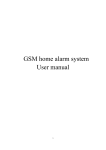
The actions in a design model are occurrences of:
❍ Call events on application interfaces of the used services;
❍ Reply events on application interfaces of the implemented service;
❍ Events on notification interfaces of the implemented service;
❍ For a main machine, call events on transfer interfaces;
❍ For a sub machine, reply events on its transfer interface.
The following figure shows the various types of events in a design model:
The various types of events in a design model
© 2012 Verum Software Technologies B.V. All rights reserved
Terms of use | Privacy Policy
http://community.verum.com/documentation/user_manual_pdf.aspx/8.3.0/concepts/models [16/08/2012 11:20:14]
ASD:Suite User Manual
●
Home
●
Product
●
Technology
●
Resources
●
Training
●
Purchase
●
Company
Sequence Based Specifications
According to the IEEE Standard Glossary of Software Engineering Terminology, a specification is a complete, precise and verifiable
description of the characteristics of a system or a component. Within ASD the distinction between an interface specification
(interface model) and a design specification (design model) is fundamental.
The interface model describes the externally visible behaviour of a component and is as implementation-free as possible. This means
that the model defines what the component does under every circumstance but not how the component will do it. The external
behaviour is specified independently of any specific implementation. It is an abstraction of the component or system
implementation that every compliant design is required to implement.
The design model describes the internal behaviour of a component. It rigorously and completely defines one of the many possible
implementations that faithfully comply with the interface model.
An ASD component implements a service (specified by the interface model) that is used by its clients. This implemented service is
exposed by means of application interfaces through which clients can send call events. The ASD component can respond to a call
event on an application interface by means of a reply event on the same application interface and events on notification interfaces.
In this process, an ASD component can also invoke used services that are implemented by other components: the servers of the ASD
component. Collectively, the services between a component and its clients and servers form an imaginary border, called the
component boundary. Information crosses the component boundary in the form of events.
Component boundary
A component "knows" only information passed into it across the component boundary in the form of the triggers it receives. A
trigger can be:
●
A call event from a client through an application interface;
●
A reply event from a server through an application interface;
●
A notification event from a server through a notification interface.
Similarly, a component exposes information to its clients and servers across the component boundary in the form of the actions it
sends. An action can be:
●
A call event to a server through an application interface;
●
A reply event to a client through an application interface;
●
A notification event to a client through a notification interface.
An interface model is defined in terms of only those events that pass between a component and its Clients. A design model is defined
in terms of events that pass between the component, its Clients and its Servers.
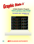
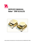
Within ASD, both interface models and design models are defined in the form of Sequence-Based Specifications (SBS). Behaviour is
specified in a tabular form as a total Black Box function, by mapping all possible sequences of triggers to the corresponding actions.
The following figure shows an SBS specified in the ASD:Suite:
An SBS in the ASD:Suite
The method used to create these specifications, is called Sequence Enumeration. This requires the systematic enumeration of all
possible input sequences of triggers, ordered by length, starting with the empty sequence. Triggers can be repeated within a
sequence and since sequence length is not restricted, the set of all possible sequences is infinite. In practice, systems do not display
an infinite set of unique, non-repeating behaviours. They cycle through a finite set of states and repeat a finite set of behaviours.
Thus the infinite set of input sequences of triggers can be reduced to a finite set of equivalence classes.
Each class is identified by a minimal length sequence, called Canonical Sequence. All sequences in a given equivalence class have the
same future system behaviour. They are said to be Mealy Equivalent. The equivalence classes form the set of states in a Mealy
http://community.verum.com/documentation/user_manual_pdf.aspx/8.3.0/concepts/sbs (1 of 2) [16/08/2012 11:20:18]
ASD:Suite User Manual
Machine.
The theory underlying this approach tells us that by reasoning about the behaviour of the finite set of Canonical Sequences, we can
reason about the behaviour of every possible input sequence. The Sequence Enumeration method used in ASD thus defines the Black
Box function as a total function between the finite set of Canonical Sequences and the corresponding actions.
© 2012 Verum Software Technologies B.V. All rights reserved
Terms of use | Privacy Policy
http://community.verum.com/documentation/user_manual_pdf.aspx/8.3.0/concepts/sbs (2 of 2) [16/08/2012 11:20:18]
ASD:Suite User Manual
●
Home
●
Product
●
Technology
●
Resources
●
Training
●
Purchase
●
Company
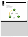
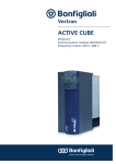
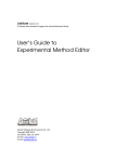
The ASD Triangle and Correctness
Architects and designer can use the ASD:Suite to create models of software components, verify their completeness and
(behavioural) correctness and generate source code from verified design models. At its core, ASD guarantees the
(mathematical) equivalence of:
1. An ASD model;
2. A formal representation of that model;
3. The source code generated from the ASD model.
This equivalence is called the ASD Triangle:
The ASD:Triangle
© 2012 Verum Software Technologies B.V. All rights reserved
Terms of use | Privacy Policy
http://community.verum.com/documentation/user_manual_pdf.aspx/8.3.0/concepts/triangle [16/08/2012 11:20:22]
ASD:Suite User Manual
●
Home
●
Product
●
Technology
●
Resources
●
Training
●
Purchase
●
Company
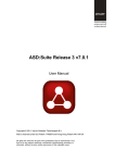
Operational semantics of rule cases
At runtime, a single detail row (a rule case) is interpreted as follows:
●
●
When the trigger occurs and the guard evaluates to "true" (or is omitted), then, as a single atomic action, all of the following occur:
❍ The actions are executed in the order in which they are specified in the "Actions" column
❍ The state variable updates are performed (using simultaneous assignment semantics)
❍ The state transition takes place.
If an action is defined as "valued", i.e. one that gives back a synchronous reply, it must be the last action in the sequence of actions.
The reply is processed as a trigger that occurs after the state transition has taken place.
The following figure shows a set of rule cases specified in an SBS:
© 2012 Verum Software Technologies B.V. All rights reserved
Terms of use | Privacy Policy
http://community.verum.com/documentation/user_manu...px/8.3.0/concepts/operational_semantics/rule_cases [16/08/2012 11:20:24]
ASD:Suite User Manual
●
Home
●
Product
●
Technology
●
Resources
●
Training
●
Purchase
●
Company
Client requests
●
●
●
●
●
●
All triggers on the Client Application Interface are implemented as method calls.
When an Application Interface trigger is executed, the execution takes place under the context of the Client's thread and the Client
code thus can't be executed until the synchronous call returns.
The response to the Client trigger, and thus its return to the client caller, takes place when the component issues an action on the
Client Application Interface. Until this occurs, the Client remains synchronously blocked.
A trigger implemented as a "void" method takes a "VoidReply" action as a signal to return to the Client.
A trigger implemented as a method returning a synchronous reply value, requires the corresponding action in order for the Client
to continue execution.
While the Client is blocked, the component can continue receiving notifications but it can not receive any other trigger from any
Client thread via any of its Client Application Interfaces. As seen by its Clients, an ASD component has Monitor semantics.
© 2012 Verum Software Technologies B.V. All rights reserved
Terms of use | Privacy Policy
http://community.verum.com/documentation/user_manua....3.0/concepts/operational_semantics/client_requests [16/08/2012 11:20:27]
ASD:Suite User Manual
●
Home
●
Product
●
Technology
●
Resources
●
Training
●
Purchase
●
Company
Notification interfaces
●
Notification interfaces exist to provide notifications to Clients.
●
Notification interfaces are implemented by the Client.
●
●
●
●
Circular control dependencies that occur when independent ASD components are composed into a system may cause deadlocks.
To prevent these, notifications are decoupled via a queue and a separate thread called the DPC Server Thread.
An action which maps onto a notification interface is always non-blocking.
Every ASD component which uses a service with at least one notification interface will automatically include a DPC Server Thread
and the decoupled calling mechanism.
All notifications are "void" events. They can have parameters, if required.
© 2012 Verum Software Technologies B.V. All rights reserved
Terms of use | Privacy Policy
http://community.verum.com/documentation/user_manua.../8.3.0/concepts/operational_semantics/notifications [16/08/2012 11:20:30]
ASD:Suite User Manual
●
Home
●
Product
●
Technology
●
Resources
●
Training
●
Purchase
●
Company
ASD Timers and the Timer Cancel Guarantee
●
ASD components can make use of the ASD Timer service by instantiating as many Timers as they need. To instantiate a Timer you
have to specify the ITimer model as a used service in the design model of the ASD component and you have to specify the
desired instances of the respective service.
Note:
❍ The ITimer interface model which needs to be specified as a used component is delivered as part of the ASD:Runtime.
❍ You must select all Application Interfaces and Notification Interfaces defined in ITimer.im as "Used Interfaces" (for details see
"Specify connected interfaces"). If you do not do so an error will be reported when you try to verify the model or generate code.
❍ The ASD timer is a special used service that can not be shared among component designs, i.e. one component can not use the ITimer
application interface of a timer component while another component uses the ITimerCB notification interface of the same timer
component.
❍ The ITimer model must not be changed. Any attempt to do so breaks the correctness guarantee provided by the ASD:Suite.
❍ You should not generate code from the ITimer.im file and you do not have to make a design for the timer component. The
implementation is provided in the ASD:Runtime.
●
●
ASD Timers implement the CreateTimer, CreateTimerMSec and CreateTimerEx triggers to start the timer for a specified duration
in seconds, milliseconds, or seconds and nanoseconds, respectively. Timer completion is signalled via the TimeOut notification event.
All ASD Timers support a CancelTimer trigger. The ASD:Runtime guarantees that once a timer has been cancelled, the TimeOut
trigger will never occur, not even if the timer has actually expired and the TimeOut event is waiting in the queue to be processed by
the DPC.
© 2012 Verum Software Technologies B.V. All rights reserved
Terms of use | Privacy Policy
http://community.verum.com/documentation/user_manu...f.aspx/8.3.0/concepts/operational_semantics/timers [16/08/2012 11:20:34]
ASD:Suite User Manual
●
Home
●
Product
●
Technology
●
Resources
●
Training
●
Purchase
●
Company
State types in a design model
Within a design model four types of state are distinguished:
●
●
●
●
Super states. These are states in the main machine in which a sub machine is active. In these Super-states, all triggers must have
"Blocked" as associated action except for the transfer reply events that correspond to the active sub machine.
Initial states of sub machines. This is the state in which the sub machine is not active (i.e. the main machine is not in the corresponding
Super state). In the Initial states of a sub machine, all triggers must have "Blocked" as associated action except for the transfer call
events that correspond to this sub machine.
Synchronous return states. These are states following a valued action, where the design is waiting for a valued reply from the called
used service (note that these synchronous return states may exist in the main machine as well as in a sub machine). In these
Synchronous return states, triggers must have "Blocked" as associated action except for the application reply events that correspond
with the called used service.
Normal states. These are all other states. In these states NONE of the external triggers (i.e. implemented service application call events
and used service notification events) may have a "Blocked" action. If no action is allowed or possible for these triggers in a normal
state, the action must be set to "Illegal". For example, when the application interface is "closed" (the Client is waiting for a reply to an
application call event). On the other hand, all application reply events and transfer reply events must have a "Blocked" action in
a normal state, since there is no application call event to a used service active, nor is there any sub machine active.
© 2012 Verum Software Technologies B.V. All rights reserved
Terms of use | Privacy Policy
http://community.verum.com/documentation/user_manual_pdf.aspx/8.3.0/concepts/state_types [16/08/2012 11:20:37]
ASD:Suite User Manual
●
Home
●
Product
●
Technology
●
Resources
●
Training
●
Purchase
●
Company
Panes and "dockable" windows
The main window of the ASD:Suite, also referred as the Master window, is by default filled in by the Start Page pane. For more
details about the Start Page pane see "The Start Page".
Next to the Start Page you can load in the Master window one or more of the following "dockable" windows:
●
●
The "Model Explorer", used to display the structure of the loaded ASD model. For more details see "The "Model Explorer" in detail"
The "Model Editor", used to display the data associated with the currently selected node in the "Model Explorer" or with the
selected Tab. The "Model Editor" is a collection of tabs specific to the loaded ASD model. As an example, we name the following
items that are displayed in the "Model Editor": the SBS, the Tags (i.e. the collection of the (derived) requirements), the States, and
the State Variables for each machine.Note:
❍
There is one Model Editor for each opened model and is entitled "<model_name> (<file_name>)".
❍
By pressing the following combination Shift key + Mouse scroll wheel you can navigate from left-to-right or right-to-left in any tab.
●
●
●
●
●
●
The "State Diagram" viewer, used to display the state diagram for the selected machine. For more details about showing state
diagrams see "Generate, Print, or Export state diagrams".
The "Verification Results", used to display the set of checks for verification. For details, see "The ASD:Suite Visual Verification User
Guide".
The "Visual Verification", used to display the information needed to fix the failed checks. For details, see "The ASD:Suite Visual
Verification User Guide".
The "Conflicts", used to display messages associated to specification conflicts. For details see "Check conflicts".
The "Output Window", used to display the progress of certain time consuming operations, like loading of an ASD model and/or
generating code. In addition to this, the size of the models involved in model checking or in code generation is also reported
together with the size of the transaction (in ASD function points).
The "Find Results", used to display the results of a "Find All" operation. For details about the shown data see "Find and Replace".
To improve data visibility, traceability and manipulation, a set of Slave windows can be opened and used to group the
available information. When you drag a "dockable" window out of the Master window or from an already created Slave window
you are automatically creating a new Slave window.
Tip: double-click the title bar of a dockable window to automatically undock it and create a new slave window.
You can drag or load as many "dockable" windows in an already created slave window, but you can not have a Start Page pane in it.
You can change the layout of a (Master or Slave) window by dragging the "dockable" windows around by their title bar to
various places in the respective window. If you drag a "dockable" window to another window, it will remember the place it last had
in that window and dock itself there.
Note: You can NOT drag Slave windows - you need to grab the title bar of the contained "dockable" window instead.
Empty Slave windows are closed automatically. The following list reflects alternatives to close a slave window:
●
Select the Slave window and press Alt+F4
●
Press the
●
Drag and drop all its "dockable" windows in the Master window or in an other Slave window
●
Close all windows docked in the Slave window. A dockable window can be closed by one of the following:
●
Press the X button in the blue window title bar,
button in the top-right corner of the window
Dockable windows in a Slave window
●
Press the
●
Deselect the item in the View menu of the Slave window (not for Model Editor windows).
button if the window is tabbed in the Slave window, or
Note:
●
●
The Master and Slave windows are normal application windows that can be a.o. minimized and maximized.
The window layout, the location of Master and Slave window(s) on the screen, is remembered per screen setup. This means that if
you switch from single to dual screen setup, you have to reorder your windows to accomodate for the dual screen setup.
© 2012 Verum Software Technologies B.V. All rights reserved
Terms of use | Privacy Policy
http://community.verum.com/documentation/user_manu...8.3.0/user_interface/tabs_panes_windows/tabs_intro [16/08/2012 11:20:40]
ASD:Suite User Manual
●
Home
●
Product
●
Technology
●
Resources
●
Training
●
Purchase
●
Company
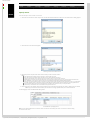
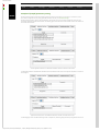
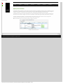
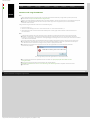
The Start Page
The information in the Start Page is grouped in the following sub-panes: Workbench, Tips & News, and Examples &
Documentation. Using the options listed in these panes you can try out features offered by the ASD:Suite, like creating new models
or opening recently opened models; you can read several tips and news related to modelling using the ASD:Suite; or you can check
out a few applications built using the ASD:Suite and you can open the user guides in your browser.
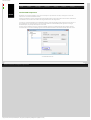
The Start Page
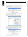
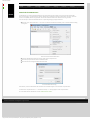
Note: By changing data in the "Appearance" tab of the "Options" dialog box, you can change the default values for the maximum to
be shown number of recently opened models and for the link to the Verum news server, you can specify if you want to open the
last opened model on start, and you can (re)enable all informative dialog boxes. These are the steps to change the data in the
"Appearance" tab of the "Options" dialog box:
●
Select the "Tools->Options" menu item.
●
Select the Appearance tab in the "Options" dialog.
●
Fill in the desired data, check/un-check the check-box and/or push the "Reset ignored dialogs" button.
See the following figure for an example:
The Appearance tab in the "Options" dialog
© 2012 Verum Software Technologies B.V. All rights reserved
Terms of use | Privacy Policy
http://community.verum.com/documentation/user_manu...8.3.0/user_interface/tabs_panes_windows/start_page [16/08/2012 11:20:44]
ASD:Suite User Manual
●
Home
●
Product
●
Technology
●
Resources
●
Training
●
Purchase
●
Company
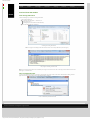
The "Model Explorer" in detail
The following figure presents the "Model Explorer" for a design model:
"Model Explorer" tree-view for a design model
Note: The indicated interface models are read-only when editing a design model. They can only be edited when the
corresponding interface model is opened separately.
For an interface model, the "Model Explorer" only displays one interface model section, for the interface currently being
edited. Clicking a node in the tree opens the respective model view and tab in the "Model Editor".
The following list introduces the nodes shown in the "Model Explorer" grouped into the following sections: a design model section
and an interface model section containing one implemented service plus zero or more used services.
1. The design model section, indicated with the
icon in the tree-view, contains the following sub-sections:
❍ The Main Machine section displays the name of the machine, a list of all states defined in this machine and a list of all the
state variables used in this machine.
The Main Machine section
❍
The Sub Machines section displays for each sub machine the name of the respective sub machine, a list of all states defined in the sub
machine, a list of all the state variables used in the sub machine and the transfer interface definition for the sub machine.
http://community.verum.com/documentation/user_...er_interface/tabs_panes_windows/model_explorer (1 of 3) [16/08/2012 11:20:48]
ASD:Suite User Manual
The Sub Machines section
❍
The Used Services section contains, for each used service respectively, the name of the used service, the name(s) of the references
(see "Specify used services") for the respective used service, and the name of the used notification interfaces.
The Used Services section
Note: Each design model has zero or more used services. There can be one or more used service references for each used service
and one or more component instances for each used service reference.
❍
The Tags node contains a list of all the defined tags.
The Tags section
2. The interface models section, indicated with the
icons in the tree-view, contains the following nodes for each interface
model respectively:
❍ The Main Machine section - same as for the design model section
❍ The Interfaces section contains one or more application interfaces, with a name for each application interface, and one or
more notification interfaces, with a name for each notification interface.
http://community.verum.com/documentation/user_...er_interface/tabs_panes_windows/model_explorer (2 of 3) [16/08/2012 11:20:48]
ASD:Suite User Manual
The Interfaces sections
❍
The Modelling Interfaces section contains a list of all modelling interfaces. Events on these interfaces represent internal behaviour of a
component and are used to trigger externally visible behaviour of the component.
The Modelling Interfaces section
❍
The Tags section - same as for the design model section
© 2012 Verum Software Technologies B.V. All rights reserved
Terms of use | Privacy Policy
http://community.verum.com/documentation/user_...er_interface/tabs_panes_windows/model_explorer (3 of 3) [16/08/2012 11:20:48]
ASD:Suite User Manual
●
Home
●
Product
●
Technology
●
Resources
●
Training
●
Purchase
●
Company
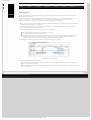
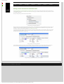
Meaning of colours in the SBS tab
The various colours used in the SBS tab of the "Model Editor" each have a meaning.
Colours used in the SBS tab
The blue rows indicate a state. The rows under a state row list all the possible triggers to the component and the corresponding
actions when the triggers occur in that state. The orange row (e.g. line 29 in the previous figure) indicates a "Floating" state. These
are states that are not reachable from the initial state. In the example above, the Activated_AlarmMode state is not present
anywhere in the "Target State" column, and thus is not reachable from the initial state.
The green cells in the "Target State" column indicate that the respective rule case defines the first transition to that particular
state. This identifies the shortest possible sequence of triggers to that particular state (the canonical sequence).
The light-blue cells in the "Target State" column (e.g. line 18 in the previous figure) indicate a transition to the same state (called
"self-transition").
The light-grey line indicates the currently "active" rule case (e.g. line 12 in the previous figure).
The dark-grey cell/line indicates the currently selected cell/line.
© 2012 Verum Software Technologies B.V. All rights reserved
Terms of use | Privacy Policy
http://community.verum.com/documentation/user_manu....3.0/user_interface/tabs_panes_windows/sbs_colours [16/08/2012 11:20:52]
ASD:Suite User Manual
●
Home
●
Product
●
Technology
●
Resources
●
Training
●
Purchase
●
Company
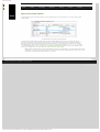
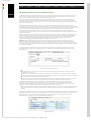
The context information field in the SBS tab
The ASD:Suite provides detailed information about a selected field in the SBS tab in an information (non-editable) field located
just above the SBS table. This field enables you to retrieve state information, for example, when during model building the name of
the current state is not visible in the "Model Editor".
The following list shows the information which is displayed in the "Context information field" when the various fields in the SBS tab are
selected:
●
If the selected field is in the "Interface" column:
❍
If the line in the SBS tab is a blue line, i.e. a line reflecting the state: "state-name"
❍
❍
●
❍
If the ASD model is an interface model or a design model and the selected interface is an application interface or a modelling
interface of the implemented service: "state-name::interface-name"
If the ASD model is a design model and the selected interface is an application interface or a notification interface of a used
service: "state-name::used-service-reference-name:interface-name".
If the selected field is in the "Event" column: "state-name::trigger-signature", where the trigger-signature contains the following
information: "used-service-reference-name:interface-name.event-name(list-of-parameters):reply-type"
used-service-reference-name - appears only if the event is declared on an application interface or on a notification interface of a
used service
❍
interface-name - the name of the interface
❍
event-name - the name of the event
❍
list-of-parameters - the parameters defined for the event together with their type
❍
reply-type - the type of the reply event: void or valued (only for call events)
●
If the selected field is in the "Actions" column: the complete sequence of actions for the selected rule case
●
If the selected field is in the "State Variable Updates" column: the complete state update expression for the selected rule case
●
If the selected field is in the "Target State" column: the name of the target state specified in the rule case
●
If the selected field is in the "Comments" column: the complete text in the field
●
If the selected field is in the "Tags" column: all specified tags in the field
The following figure shows an example of data shown in the "Context information field" when:
●
The ASD model is a design model
●
The selected field is in the "Event" column
●
The event belongs to a notification interface of a used service
The Context information field in the SBS tab
© 2012 Verum Software Technologies B.V. All rights reserved
Terms of use | Privacy Policy
http://community.verum.com/documentation/user_manu....0/user_interface/tabs_panes_windows/context_field [16/08/2012 11:20:55]
ASD:Suite User Manual
●
Home
●
Product
●
Technology
●
Resources
●
Training
●
Purchase
●
Company
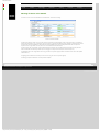
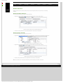
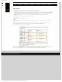
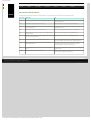
The File menu
New...
Open…
Menu Item
Save
Save <model_name> As...
Properties
Shortcut Key
Purpose
Ctrl+N
To create a new ASD model. For details see "Create ASD models".
Ctrl+O
To open an ASD model or a model verification results file. For details, see "Load and
close ASD models".
Ctrl+S
To save the current ASD model. For details, see "Save ASD models".
To save an exact copy of the currently selected model or to create a new model based
on the current one. For details, see "Save ASD models".
Alt+F7
To open the Properties dialog of the active model.
Note: This dialog is used for specification of properties to be used in verification
and code generation.
Close
Reassign Interface Model Dependencies...
Page Setup...
Print...
Exit
Alt+F4
To close the current ASD model.
To change the interface model dependencies within a design model. For details, see
"Reassign interface model dependencies in a design model".
To setup the page for printing. For details see "Print ASD models".
To print the current ASD model. For details, see "Print ASD models".
To close the current ASD:Suite session.
Note: In addition to the presented items in the File menu you will see a list of recently opened models presented between the
“Close” and “Reassign Interface Model Dependencies…” items. You determine the maximum number of models to be listed
by specifying the size of the recent models list in the Options dialog obtained via “Tools-->Options” under the “Appearance” tab.
© 2012 Verum Software Technologies B.V. All rights reserved
Terms of use | Privacy Policy
http://community.verum.com/documentation/user_manual_pdf.aspx/8.3.0/user_interface/menus/file [16/08/2012 11:20:58]
ASD:Suite User Manual
●
Home
●
Product
●
Technology
●
Resources
●
Training
●
Purchase
●
Company
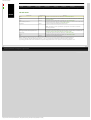
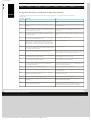
The Edit menu
Menu Item
Undo
Redo
Cut
Copy
Paste
Delete
Shortcut Key
Ctrl+Z
Ctrl+Y
Ctrl+X
Ctrl+C
Ctrl+V
Del
Purpose
To undo an action.
To redo an undone action.
To cut the selected data to the Clipboard.
To copy the selected data to the Clipboard.
To paste the contents of the Clipboard.
To empty the data from the selected cell(s).
Find...
Replace...
Ctrl+F
Ctrl+H
Note: There are cells in the ASD model for which this operation is not allowed.
To search data in the ASD model. For details see "Find and Replace in ASD models".
To replace data in the ASD model. For details see "Find and Replace in ASD models".
© 2012 Verum Software Technologies B.V. All rights reserved
Terms of use | Privacy Policy
http://community.verum.com/documentation/user_manual_pdf.aspx/8.3.0/user_interface/menus/edit [16/08/2012 11:21:01]
ASD:Suite User Manual
●
Home
●
Product
●
Technology
●
Resources
●
Training
●
Purchase
●
Company
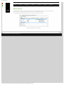
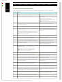
The View menu
Menu Item
Model Explorer
Output Window
Conflicts
Find Results
Verification Results
Visual Verification
State Diagram
Shortcut Key
Purpose
To open or close the “Model Explorer”.
To open or close the “Output Window”.
To open or close the “Conflicts” window.
To open or close the “Find Results” window.
To open or close the “Verification Results” window.
To open or close the “Visual Verification” window.
To open or close the “State Diagram” viewer.
Note: Each Slave window has its own View menu with the same content as the View menu in the Main Window. The difference is
that the selection of the items in the View menu of a slave window reflects the currently opened "dockable" windows in the
respective slave window.
© 2012 Verum Software Technologies B.V. All rights reserved
Terms of use | Privacy Policy
http://community.verum.com/documentation/user_manual_pdf.aspx/8.3.0/user_interface/menus/view [16/08/2012 11:21:05]
ASD:Suite User Manual
●
Home
●
Product
●
Technology
●
Resources
●
Training
●
Purchase
●
Company
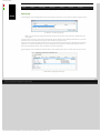
The Filters menu
Menu Item
Hide Illegal
Hide Blocked
Hide Disabled
Hide Invariant
Hide Self Transitions
Custom Filter
Edit Custom Filter...
Apply Filters
Shortcut Key
Ctrl+Shift+I
Ctrl+Shift+B
Ctrl+Shift+D
Ctrl+Shift+V
Ctrl+Shift+S
Ctrl+Shift+C
Ctrl+Shift+E
Ctrl+Shift+A
Purpose
To select or deselect the “Hide Illegal” filter and to apply the current filter selection.
To select or deselect the “Hide Blocked” filter and to apply the current filter selection.
To select or deselect the “Hide Disabled” filter and to apply the current filter selection.
To select or deselect the “Hide Invariant” filter and to apply the current filter selection.
To select or deselect the “Hide Self Transitions” filter and to apply the current filter selection.
To select or deselect the user specified filter and to apply the current filter selection.
To edit the custom filter. For details see "Editing the custom filter".
To apply current filter selection to all data displayed in the SBS tabs of loaded models.
© 2012 Verum Software Technologies B.V. All rights reserved
Terms of use | Privacy Policy
http://community.verum.com/documentation/user_manual_pdf.aspx/8.3.0/user_interface/menus/filters [16/08/2012 11:21:07]
ASD:Suite User Manual
●
Home
●
Product
●
Technology
●
Resources
●
Training
●
Purchase
●
Company
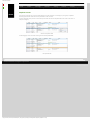
The Verification menu
Menu Item
Verify...
Verify All
Verify Again
Open Verification Results...
Stop Verifying
Show Previous Failure
Show Next Failure
Forward Step Over
Forward Step Into
Forward Step Out
Forward Step Rule Case
Backward Step Over
Backward Step Into
Backward Step Out
Backward Step Rule Case
Step To First
Step To Last
Shortcut Key
Purpose
F5
To verify the selected ASD model. For details, see "Verify an ASD model".
Shift+F5
To run all checks for the selected ASD model. For details, see "Verify an ASD model".
Ctrl+Shift+F5
To re-run the last verification. For details, see "Verify an ASD model".
To open a model verification results file.
Shift+F5
To abort a verification.
Ctrl+F6
To show in the Visual Verification window the first example of the previous failed check.
F6
To show in the Visual Verification window the first example of the next failed check.
F10
To step over the next item in the currently focused SBS tab. For details about interactive visual
verification see "The ASD:Suite Visual Verification Guide".
F11
To step into the current item in the currently focused SBS tab. For details about interactive visual
verification see "The ASD:Suite Visual Verification Guide".
Shift+F11
To step out from the SBS tab of a sub machine or a used service machine to the next item in the
main machine. For details about interactive visual verification see "The ASD:Suite Visual Verification
Guide".
F12
To step to the next rule case in the currently focused SBS tab. For details about interactive visual
verification see "The ASD:Suite Visual Verification Guide".
Ctrl+F10
To step backwards over the next item in the currently focused SBS tab. For details about interactive
visual verification see "The ASD:Suite Visual Verification Guide".
Ctrl+F11
To step backwards into the current item in the currently focused SBS tab. For details about
interactive visual verification see "The ASD:Suite Visual Verification Guide".
Ctrl+Shift+F11 To step out from the SBS tab of a sub machine or a used service machine to the previous item in the
main machine. For details about interactive visual verification see "The ASD:Suite Visual Verification
Guide".
Ctrl+F12
To step to the previous rule case in the currently focused SBS tab. For details about interactive visual
verification see "The ASD:Suite Visual Verification Guide".
Ctrl+F9
To step to the first item in the trace. For details about interactive visual verification see "The ASD:
Suite Visual Verification Guide".
F9
To step to the last item in the trace (which is typically the error (warning sign)). For details about
interactive visual verification see "The ASD:Suite Visual Verification Guide".
© 2012 Verum Software Technologies B.V. All rights reserved
Terms of use | Privacy Policy
http://community.verum.com/documentation/user_manual_pdf.aspx/8.3.0/user_interface/menus/verification [16/08/2012 11:21:11]
ASD:Suite User Manual
●
Home
●
Product
●
Technology
●
Resources
●
Training
●
Purchase
●
Company
The Tools menu
Menu Item
Reconcile
Check Conflicts
Fix Conflicts
Generate Code
Shortcut Key
F8
Shift+F8
F7
Generate Code With...
Shift+F7
Generate All Code
Generate Stub...
Ctrl+F7
Download Runtime...
Upgrade Models...
Compare
Purpose
To acknowledge the fix of reconcile conflicts. For details, see "Fix reconcile conflicts".
To check the ASD model for specification conflicts. For details, see "Check conflicts".
To check the ASD model for specification conflicts and to fix those that can be automatically fixed.
To generate code for the selected ASD model. For details on code generation see "Generate code from
an ASD model".
To generate code for the selected ASD model using a different target language and/or code generator
version than the ones specified in the model properties. For details on code generation see "Generate
code from an ASD model".
To generate code for all opened models (stub code for interface models is not generated).
To generate header file and stub code for the selected interface model. For details about stub code
generation for interface models see "Generate stub code from an ASD interface model".
To download the ASD:Runtime. For details, see "Download the ASD:Runtime".
To upgrade all models in a selected folder and in its sub folders. For details see "Upgrade ASD models".
To start model compare using the ASD:Compare.
Note:
● The selected model is loaded as the Master.
●
Generate State Diagram
Determine Model Size
Connect...
Options
F4
This option is greyed out (disabled) if the ASD:Compare is not installed or there is no ASD model
loaded.
For details see the "ASD:Compare User Guide".
To generate or to update the state diagram displayed in the State Diagram viewer for the selected
machine. For details see "Generate, Print, or Export state diagrams".
To report the size (in ASD function points) of all open models. The result is visible in the "Output
Window".
To establish a connection to the ASD Server or to connect as a different user. For details see "How to set
up the ASD:Suite".
To specify a set of ASD:Suite specific settings, like connection parameters to be able to connect to the
ASD Server (see "How to set up the ASD:Suite") or settings for the appearance of the Start Page.
© 2012 Verum Software Technologies B.V. All rights reserved
Terms of use | Privacy Policy
http://community.verum.com/documentation/user_manual_pdf.aspx/8.3.0/user_interface/menus/tools [16/08/2012 11:21:14]
ASD:Suite User Manual
●
Home
●
Product
●
Technology
●
Resources
●
Training
●
Purchase
●
Company
The Help menu
Examples
Menu Item
Shortcut Key
ASD:Suite User Manual
ASD:Suite Visual Verification Guide
ASD:Runtime Guide
ASD:Suite Release Notes
ASD:Suite Keyboard Shortcuts
Verum Website
Verum ASD:Suite Community Website
Verum ASD:Portal
About ASD:Suite
Purpose
To facilitate access to a set of applications built using the ASD:Suite (by opening a page in
your default web browser).
To open the user manual for the current ASD:Suite (in your default web browser).
To open the user guide for ASD:Suite Visual Verification (in your default web browser).
To open the user guide for the current ASD:Runtime (in your default web browser).
To open the release notes for the current ASD:Suite (in your default web browser).
To open the list of keyboard shortcuts for the current ASD:Suite (in your default web
browser).
To open the Verum website (in your default web browser).
To open the ASD:Suite Community website (in your default web browser).
To open the ASD:Portal website (in your default web browser).
To display the version number and the “Revision ID” for the ASD:Suite and the associated
copyright statement.
© 2012 Verum Software Technologies B.V. All rights reserved
Terms of use | Privacy Policy
http://community.verum.com/documentation/user_manual_pdf.aspx/8.3.0/user_interface/menus/help [16/08/2012 11:21:17]
ASD:Suite User Manual
●
Home
●
Product
●
Technology
●
Resources
●
Training
●
Purchase
●
Company
The main toolbar
Toolbar buttons on the main toolbar
Picture
Name
Shortcut key
Purpose
New
Ctrl+N
To create a new ASD model. For details see "Create ASD models".
Open
Ctrl+O
To open an ASD model or a model verification results file. For details, see "Load and close ASD
models".
Save
Ctrl+S
To save the current ASD model. For details, see "Save ASD models".
To print the current ASD model. For details, see "Print ASD models".
Print
Undo
Ctrl+Z
To undo an action.
Redo
Ctrl+Y
To redo an undone action.
Cut
Ctrl+X
To cut the selected data to the Clipboard.
Copy
Ctrl+C
To copy the selected data to the Clipboard.
Paste
Ctrl+V
To paste the contents of the Clipboard.
Delete
Del
Find
Ctrl+F
To search or replace data in ASD model(s). For details, see "Find and Replace".
Apply Filters
Ctrl+Shift+A
To apply current filter selection to all data displayed in the SBS tabs of loaded models.
Edit Custom Filter
Ctrl+Shift+E
To edit the custom filter. For details see "Editing the custom filter".
Check Conflicts
F8
To check the ASD model for specification conflicts. For details, see "Check conflicts".
Fix Conflicts
Shift+F8
To check the ASD model for specification conflicts and to fix those that can be automatically fixed.
Generate Code
F7
To generate code for the selected ASD model. For details on code generation see "Generate code
from an ASD model".
Generate Code With
Shift+F7
To generate code for the selected ASD model using a different target language and/or code
generator version than the ones specified in the model properties. For details on code
generation see "Generate code from an ASD model".
Generate All Code
Ctrl+F7
To generate code for all opened models (stub code for interface models is not generated).
To empty the data from the selected cell(s).
Note: This operation is not allowed for all cells in the ASD model.
To open the Properties dialog of the active model.
Properties
Alt+F7
Note: This dialog is used for specification of properties to be used in verification and code
generation.
Generate State
Diagram
F4
To generate or to update the state diagram displayed in the State Diagram viewer for the
selected machine. For details see "Generate, Print, or Export state diagrams".
Verify
F5
To verify the selected ASD model. For details, see "Verify an ASD model".
Verify All
Shift+F5
To run all checks for the selected ASD model. For details, see "Verify an ASD model".
Verify Again
Ctrl+Shift+F5 To re-run the last verification. For details, see "Verify an ASD model".
Show Previous Failure
Ctrl+F6
To show in the Visual Verification window the first example of the previous failed check.
Show Next Failure
F6
To show in the Visual Verification window the first example of the next failed check.
Step To First
Ctrl+F9
To step to the first item in the trace. For details about interactive visual verification see "The ASD:
Suite Visual Verification Guide".
Step To Last
F9
To step to the last item in the trace (which is typically the error (warning sign)). For details about
interactive visual verification see "The ASD:Suite Visual Verification Guide".
© 2012 Verum Software Technologies B.V. All rights reserved
Terms of use | Privacy Policy
http://community.verum.com/documentation/user_manual_pdf.aspx/8.3.0/user_interface/buttons/main [16/08/2012 11:21:21]
ASD:Suite User Manual
●
Home
●
Product
●
Technology
●
Resources
●
Training
●
Purchase
●
Company
The "debugging" toolbar
Toolbar buttons on the "Model Editor"
Picture
Name
Shortcut Key
Purpose
Forward Step Over
F10
To step over the next item in the currently focused SBS tab. For details about interactive visual
verification see "The ASD:Suite Visual Verification Guide".
Forward Step Into
F11
To step into the current item in the currently focused SBS tab. For details about interactive
visual verification see "The ASD:Suite Visual Verification Guide".
Forward Step Out
Shift+F11
To step out from the SBS tab of a sub machine or a used service machine to the next item in
the main machine. For details about interactive visual verification see "The ASD:Suite Visual
Verification Guide".
Forward Step Rule Case
F12
To step to the next rule case in the currently focused SBS tab. For details about interactive
visual verification see "The ASD:Suite Visual Verification Guide".
Backward Step Over
Ctrl+F10
To step backwards over the next item in the currently focused SBS tab. For details about
interactive visual verification see "The ASD:Suite Visual Verification Guide".
Backward Step Into
Ctrl+F11
To step backwards into the current item in the currently focused SBS tab. For details about
interactive visual verification see "The ASD:Suite Visual Verification Guide".
Backward Step Out
Ctrl+Shift
+F11
To step out from the SBS tab of a sub machine or a used service machine to the previous item
in the main machine. For details about interactive visual verification see "The ASD:Suite Visual
Verification Guide".
To step to the previous rule case in the currently focused SBS tab. For details about interactive
Backward Step Rule
Ctrl+F12
visual verification see "The ASD:Suite Visual Verification Guide".
Case
Note: This toolbar is only shown during debugging a failure trace.
© 2012 Verum Software Technologies B.V. All rights reserved
Terms of use | Privacy Policy
http://community.verum.com/documentation/user_manual_pdf.aspx/8.3.0/user_interface/buttons/debugging [16/08/2012 11:21:24]
ASD:Suite User Manual
●
Home
●
Product
●
Technology
●
Resources
●
Training
●
Purchase
●
Company
The state diagram viewer toolbar
Toolbar buttons on the "State Diagram" viewer
Picture
Name
Shortcut Key
Purpose
Export
Ctrl+Shift+X
To export the state diagram for the selected machine. For detail see "Generate, Print, or Export
state diagrams".
Print
Alt+P
To print the current state diagram.
Zoom In
Ctrl++
To zoom-in in the current state diagram.
Zoom Out
Ctrl+-
To zoom-out in the current state diagram.
Fit height
Ctrl+Shift+H To fit the state diagram in the available window height.
Fit width
Ctrl+Shift+W To fit the state diagram in the available window width.
Fit page
Ctrl+0
To fit the state diagram in the available window size.
Show self transitions
Ctrl+Shift+T
To enable/disable showing self transitions in the state diagram.
Show floating states
Ctrl+Shift+L
To enable/disable showing floating states in the state diagram.
Follow custom filter
To display data in accordance with the custom filter settings. For example, if there is a custom
filter defined and it is selected, and the “Follow custom filter” button is selected, the filtered out
data is not shown in the state diagram.
Merge transitions
To enable/disable the merge of duplicate transitions when “Show triggers” and “Show actions”
are disabled.
Show triggers
To enable/disable showing of triggers in the state diagram.
Show actions
To enable/disable showing of actions in the state diagram.
Show arguments
To enable/disable showing of arguments in the state diagram.
Show guards
To enable/disable showing of guards and state variable updates in the state diagram.
Ordering top to bottom Ctrl+Shift+O To change the orientation of the state diagram to "top to bottom".
Ordering left to right
Ctrl+Shift+O To change the orientation of the state diagram to "left to right".
Set fonts
Ctrl+Shift+F
To change the font settings for the data displayed in the state diagram.
Refresh state diagram
Ctrl+Shift+R
To refresh the data displayed in a state diagram after a change in the SBS of the associated
machine.
© 2012 Verum Software Technologies B.V. All rights reserved
Terms of use | Privacy Policy
http://community.verum.com/documentation/user_manual_pdf.aspx/8.3.0/user_interface/buttons/state_diagram [16/08/2012 11:21:28]
ASD:Suite User Manual
●
Home
●
Product
●
Technology
●
Resources
●
Training
●
Purchase
●
Company
Status bar
The status bar is located at the bottom of the main window. The following information is shown in the status bar, from left to right:
●
Status information. The status of current actions is displayed in one line on the left side. The following figure shows status
information during loading of an ASD model.
Status information on the status bar
●
Verification progress bar. Via this progress bar you can follow the progress of verification. The following figure shows the progress of
verification,
Verification progress in the status bar
while the next figure shows the reporting of a verification end:
Verification end shown in the status bar
Note: The number of the rectangles shown in the verification progress bar is the same as the number of (to be) performed checks.
The following list contains an explanation for the items which appear in the verification progress bar:
❍ The red cross: the button to stop verification or debugging
❍ A green rectangle: a successful check
❍ A red rectangle: a failed check
❍ A grey rectangle: a check waiting to be performed
❍ A light blue rectangle with a running circle: a performing check
❍ A blue rectangle: a failed check due to an internal error
❍ A yellow rectangle: a skipped check
●
The size (in ASD function points) for the currently selected ASD model.
Note: A "*" after the model size number indicates that the changes to your model are not yet reflected in the model size number.
Use "Tools-->Determine Model Size" to recalculate the model size.
●
The target language for code generation and the version of the generator to be used. Possible values of this information field:
❍
Empty: when no model is opened.
❍
LANGUAGE (VERSION): when an ASD model is opened but neither the target language nor the code generator version are specified.
❍
●
<target_language> (<generator_version>): For example "C (8.0.0)" when target_language is C and the generator_version is "8.0.0".
Note: Code generation language and version properties are captured in the model properties section and are stored in the ASD
model file. This allows you to specify the desired target language and code generator version for each model when information is
missing or not according to your expectations. For details about the selection and specification of the target language and code
generator version see " Specify target language and code generator version".
The status of the connection to the ASD:Server, i.e. "Connected", "Disconnected" or "Reconnecting".
© 2012 Verum Software Technologies B.V. All rights reserved
Terms of use | Privacy Policy
http://community.verum.com/documentation/user_manual_pdf.aspx/8.3.0/user_interface/status_bar [16/08/2012 11:21:31]
ASD:Suite User Manual
●
Home
●
Product
●
Technology
●
Resources
●
Training
●
Purchase
●
Company
Build ASD components
These are the steps to build an ASD component using the ASD:Suite:
1. Create an interface model that specifies the service that is going to be implemented by the component. For details see
"Create interface models".
2. Identify the used services, i.e. services that provide functionality that is going to be used in the design of the component.
3. For each used service, identify one or more components that implement that service.
4. Create the design model for the considered component:
❍
Specify the service that is going to be implemented.
❍
Specify the services that are going to be used.
❍
Designate components for the used services.
❍
Build the SBS for the design model.
The construction of an Alarm System is used to illustrate the above mentioned steps. The following figure presents the main
component of such a system (the box named "AlarmSystem"), together with the service to implement, AlarmSystem, and the
services to be used: Sensor and Siren:
© 2012 Verum Software Technologies B.V. All rights reserved
Terms of use | Privacy Policy
http://community.verum.com/documentation/user_manual_pdf.aspx/8.3.0/basic_modelling/workflow [16/08/2012 11:21:34]
ASD:Suite User Manual
●
Home
●
Product
●
Technology
●
Resources
●
Training
●
Purchase
●
Company
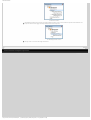
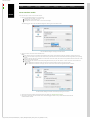
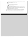
Create interface models
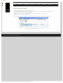
These are the steps to create a new interface model:.
1. Open the "New Model" dialog. This can be done by:
❍ Selecting the "File->New..." menu item, or by
❍ Clicking "New" in the Toolbar, or by
❍ Selecting the "Create a new model..." item on the Start Page.
The following figure shows the "New Model" dialog after selecting one of the above choices:
The "New Model" dialog for creating an interface model
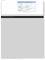
2. Specify a name for the service under "Model name:"
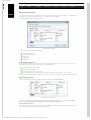
Note:
❍ If the field was empty, the specified name designates the file name of the interface model (see next figure) and the name of the
service. You should not use spaces in this name and no special characters which would make the file unrecognisable by the operating
system.
❍ If there is already a file name specified in the "File location and name:" field, the file name is not updated when the information in the
"Model name:" field is changed.
❍ You can specify a file name in the file lookup dialog obtained when you press the "Browse..." button next to the "File location and
name:" field
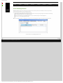
■ If the "Model name:" field was empty, the name of the service will be the same as the name of the file.
■ If the "Model name:" field was not empty, the name of the service will not be changed after the file is selected.
The "New Model" dialog for interface models after specifying a service name
3. Specify the execution model for this interface model. For details see "Specify execution model".
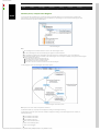
4. Click "OK" to create and save the interface model. The following figure shows a newly created interface model with all
dockable windows loaded.
http://community.verum.com/documentation/user_m...0/basic_modelling/create/create_interface_model (1 of 2) [16/08/2012 11:21:38]
ASD:Suite User Manual
A newly created interface model
Note: To change the name of the service, select the service name in the "Model Explorer", press F2 or double click, and type in a
new name. This does not change the name of the file.
The following tabs are shown in the "IAlarm (IAlarm.im)", which is the "Model Editor" for the IAlarm.im:
●
IAlarm: a tab for the main machine, containing the following sub-tabs:
❍
SBS: shows the SBS for the machine;
❍
States: shows the list of states defined in the machine and facilitates the specification of informal design information about the states;
❍
State Variables: shows the list of state variables defined for the machine and facilitates the declaration and specification of
state variables.
Note: In an interface model there is only one machine.
●
Application Interfaces: shows the set of call events and reply events for each defined application interface and facilitates
the specification of new application events.
●
Note: There is one sub-tab per defined interface.
Notification Interfaces: shows the set of events for each defined notification interface and facilitates the specification of
new notification events.
●
Note: There is one sub-tab per defined interface.
Modelling Interfaces: shows the set of events for each defined modelling interface and facilitates the specification of new
notification events.
●
Note: There is one sub-tab per defined interface.
Tags: shows the list of requirements defined for the component and facilitates the specification of additional requirements
that emerge during the design phase.
Note: The ASD:Suite enables you to create a new model based on an existing model of the same type. For details see "Create an
ASD model from an existing one".
© 2012 Verum Software Technologies B.V. All rights reserved
Terms of use | Privacy Policy
http://community.verum.com/documentation/user_m...0/basic_modelling/create/create_interface_model (2 of 2) [16/08/2012 11:21:38]
ASD:Suite User Manual
●
Home
●
Product
●
Technology
●
Resources
●
Training
●
Purchase
●
Company
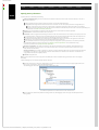
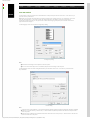
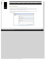
Create application interfaces
These are the alternatives for creating a new application interface:
● Select the "New Application Interface" item in the context menu shown when pressing the right mouse button while selecting
the "Application Interfaces" node in the "Model Explorer".
●
Press the "New" button in the "Application Interfaces" tab, i.e. the white plus sign on a blue background.
●
Press "Ctrl+T" in the "Application Interfaces" tab.
Note: The application interface is created after you specified a name in the dialog that appears and confirm it with the OK button.
Interface model - The "Application Interfaces" tab
© 2012 Verum Software Technologies B.V. All rights reserved
Terms of use | Privacy Policy
http://community.verum.com/documentation/user_manua...basic_modelling/create/create_application_interface [16/08/2012 11:21:42]
ASD:Suite User Manual
●
Home
●
Product
●
Technology
●
Resources
●
Training
●
Purchase
●
Company
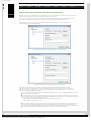
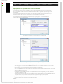
Specify events for application interfaces
These are the steps to declare application call events and application reply events:
1. Select an existing application interface or create a new one. For details on creating a new application interface see "Create
application interfaces".
Note: To select an application interface you can select the node in the "Model Explorer" window or you can use "Ctrl+PageDown"
and "Ctrl+PageUp".
2. Specify call events and reply events for the selected application interface
❍ Specify call events
In order to declare a call event, you must type the name of the event together with the list of parameters in the "Event" column.
You may also add a description in the "Comments" column.
Note:
An application call event is either "void" or "valued". A "void" event corresponds to a void method in C++. That is, it does not have a
return value. A "valued" event corresponds to a C++ method that returns a value. You must explicitly declare the event type, i.e.
whether the event is "void" or "valued".
■ An application call event might have [in], [out] or [inout] parameters. For details on parameter declaration and semantics, see
"Define and use parameters".
■ The background of the cell in which you specify an event is coloured red if the declaration is not syntactically correct. The event is
not stored in the model until the declaration is correct. The name of the event must conform to the syntactical rules for names used
in ASD modelling. For details, see "Syntactical rules for names used in ASD modelling".
The following figure shows an example of specifying "void" and "valued" events without parameters for the IAlarm interface:
■
Specify application call events
Each application call event is automatically added as a trigger in the "NewState" state shown in the SBS tab. The following figure shows
the effect that the specification of application call events has on the SBS of the main machine (in this example "IAlarm"):
Specified application call events in the SBS
Note: Each "valued" event is tagged with a "+" symbol to provide a visual differentiation between "valued" and "void" events.
❍
Specify reply events
In order to specify application reply events, you must type the name of the event in the "Reply Event" column. You may also add
a description in the "Comments" column.
Note:
Application reply events should be specified only at least one "valued" event was specified.
Application reply events have no parameters and have no type declaration.
The following figure shows an example where application reply events have been specified for the "IAlarm" application interface:
■
■
http://community.verum.com/documentation/user_m...sic_modelling/create/specify_application_events (1 of 2) [16/08/2012 11:21:46]
ASD:Suite User Manual
Specify application reply events
© 2012 Verum Software Technologies B.V. All rights reserved
Terms of use | Privacy Policy
http://community.verum.com/documentation/user_m...sic_modelling/create/specify_application_events (2 of 2) [16/08/2012 11:21:46]
ASD:Suite User Manual
●
Home
●
Product
●
Technology
●
Resources
●
Training
●
Purchase
●
Company
Create notification interfaces
These are the alternatives for creating a new notification interface:
● Select the "New Notification Interface" item in the context menu shown when pressing the right mouse button while selecting
the "Notification Interfaces" node in the "Model Explorer".
●
Press the "New" button in the "Notification Interfaces" tab, i.e. the white plus sign on a blue background.
●
Press "Ctrl+T" in the "Notification Interfaces" tab.
Note: The notification interface is created after you specify a name in the dialog that appears and confirm it with the OK button.
Interface model - The "Notification Interfaces" tab
© 2012 Verum Software Technologies B.V. All rights reserved
Terms of use | Privacy Policy
http://community.verum.com/documentation/user_manual...basic_modelling/create/create_notification_interface [16/08/2012 11:21:49]
ASD:Suite User Manual
●
Home
●
Product
●
Technology
●
Resources
●
Training
●
Purchase
●
Company
Specify events for notification interfaces
A notification interface is an interface that is defined by the component being specified, but which must be implemented by the
clients of the component.
In order to declare a notification event, you have to type the name of the event together with the list of parameters in the
"Event" column. You may also add a description in the "Comments" column.
Note:
●
For now, disregard the check-box named "Broadcast". For details, see "Specify publishers and observers".
●
Notification events have no result type.
●
The background of the cell in which you specify an event is coloured red if the declaration is not syntactically correct. The event is
not stored in the model until the declaration is correct. The name of the event must obey the syntactical rules for names used in
ASD modelling. For details, see "Syntactical rules for names used in ASD modelling".
The following figure shows an example where notification events without parameters have been specified for the
"IAlarm_NI" notification interface:
Specify notification events
© 2012 Verum Software Technologies B.V. All rights reserved
Terms of use | Privacy Policy
http://community.verum.com/documentation/user_manua.../basic_modelling/create/specify_notification_events [16/08/2012 11:21:52]
ASD:Suite User Manual
●
Home
●
Product
●
Technology
●
Resources
●
Training
●
Purchase
●
Company
Create modelling interfaces
Modelling interfaces contain events that are not externally visible, but that represent internal behaviour of the component that
results in externally visible events (e.g. notification events)
These are alternatives for creating a new modelling interface:
● Select the "New Modelling Interface" item in the context menu shown when pressing the right mouse button while selecting
the "Modelling Interfaces" node in the "Model Explorer".
●
Press the "New" button in the "Modelling Interfaces" tab, i.e. the white plus sign on a blue background.
●
Press "Ctrl+T" in the "Modelling Interfaces" tab.
Note: The modelling interface is created after you specify a name in the dialog that appears and confirm it with the OK button.
Interface model - The "Modelling Interfaces" tab
© 2012 Verum Software Technologies B.V. All rights reserved
Terms of use | Privacy Policy
http://community.verum.com/documentation/user_manua...0/basic_modelling/create/create_modelling_interface [16/08/2012 11:21:55]
ASD:Suite User Manual
●
Home
●
Product
●
Technology
●
Resources
●
Training
●
Purchase
●
Company
Specify events for modelling interfaces
Modelling interfaces contain events that are not externally visible, but that represent internal behaviour of the component that
results in externally visible events (e.g. notification events)
In order to declare an event, you must type the name of the event in the "Event" column and specify whether the event is
"Inevitable" or "Optional" in the "Abstraction Type" column. You may also add a description in the "Comments" column.
Note:
●
Modelling events have no result type.
●
Modelling events can not have parameters.
●
The background of the cell in which you specify an event is coloured red if the declaration is not syntactically correct. The event is
not stored in the model until the declaration is correct. The name of the event must obey the syntactical rules for names used in
ASD modelling. For details, "Syntactical rules for names used in ASD modelling".
Modelling events contain an indicator whether the event is optional (it may occur or not, e.g. an error event) or inevitable (if
nothing else happens, this event will always occur, e.g. a time-out event). The indicator has the following effect on the verification:
in case of "Inevitable" only the cases when the event occurs are investigated, while in case of "Optional" also the situation(s) when
the respective event does not occur are checked.
In the SBS, any modelling event must have "Disabled" action if that event will not occur in a specific state.
The following figure shows an example where modelling events have been specified for the "InternalEvents" modelling interface:
Specify modelling events
Each modelling event is automatically added as trigger in the "NewState" state shown in the SBS tab. The following figure shows
the effect that the specification of modelling events has on the SBS tab of the main machine (in this example "IAlarm"):
Specified modelling call events in the SBS
© 2012 Verum Software Technologies B.V. All rights reserved
Terms of use | Privacy Policy
http://community.verum.com/documentation/user_manu....0/basic_modelling/create/specify_modelling_events [16/08/2012 11:21:58]
ASD:Suite User Manual
●
Home
●
Product
●
Technology
●
Resources
●
Training
●
Purchase
●
Company
Create design models
Note: In order to create a design model, you must already have created the interface model for the implemented service. See
"Create interface models" for guidelines on creating an interface model.
These are the steps to create a new design model:
1. Open the "New Model" dialog. This can be done by:.
❍ Selecting the "File->New..." menu item, or by
❍ Clicking "New" in the Toolbar, or by
❍ Selecting the "Create a new model..." item on the Start Page.
2. Select the design model icon in the left pane.
3. Specify a name for the service under "Model name:"
Note:
❍ If the field was empty, the specified name designates the file name of the design model and the name of the component. You
should not use spaces in this name and no special characters which would make the file unrecognisable by the operating system.
❍ If there is already a file name specified in the "File location and name:" field, the file name is not updated when the information in the
"Model name:" field is changed.
❍ You can specify a component name by specifying a file name in the file lookup dialog obtained when you press the "Browse..."
button next to the "File name:" field
■ If the "Model name:" field was empty, the name of the component will be the same as the name of the file.
■ If the "Model name:" field was not empty, the name of the component will not be changed after the file is selected.
The following figure shows the "New Model" dialog after you have selected the design model icon in the left pane and you
specified "Alarm" as name for your design model:
The "New Model" dialog for creating design models
4. Specify the implemented service by filling in the path or by selecting the file using the "Browse..." button next to the
"Implement interface model:" field.
Note: You are able to specify if you would like to create the SBS of the design model based on the SBS of the specified
implemented interface model. This can be done by checking the "Copy SBS from interface model" checkbox.
5. Specify the component type for the ASD component. For details see "Specify component type".
6. Click "OK".
When you click OK, a new design model is created, saved and opened.
Note:
❍
❍
To change the name of the component, double click on the component name and type a new name. You may also do this by selecting
the component name in the "Model Explorer" window and pressing F2. This does not change the name of the file
The following tabs are shown in the "Alarm (Alarm.dm)", which is the "Model Editor" for the Alarm.dm:
■ Alarm: a tab for the main machine, containing the following sub-tabs:
■ SBS: shows the SBS for the machine;
■ States: shows the list of states defined in the machine and facilitates the specification of informal design information about the
states;
■ State Variables: shows the list of state variables defined for the machine and facilitates the declaration and specification of state
variables.
Note: In a design model, there might be more machines: one main machine and zero or more sub machines. For details about
adding and using sub machines, see "Add sub machines".
Used Services: shows the list of used services together with the interfaces that are used in three sub-tabs: Primary References,
Secondary References and Used Notification Interfaces. For details about used services, see "Specify used services"
■ Tags: shows the list of requirements defined for the component and facilitates the specification of additional requirements that
emerge during the design phase.
In the remainder of this user guide, we use "Alarm" as the name of the component and the main machine.
The ASD:Suite ensures that the set of all triggers in each state of each machine of the design model is consistent with the set of
events of the implemented service and used services.
The following is copied from the interface model into the design model if you have checked the "Copy SBS from interface model"
check box:
■ The states of the main machine with all information stored in the interface model (user columns and descriptions).
■ The state variables of the main machine.
■ The tags.
■ The SBS of the main machine, with the exception of the rule cases that have a modelling event as trigger.
■
❍
❍
❍
Note: The ASD:Suite enables you to create a new model based on an existing model of the same type. For details see "Create an
ASD model from an existing one".
© 2012 Verum Software Technologies B.V. All rights reserved
http://community.verum.com/documentation/user_...3.0/basic_modelling/create/create_design_model (1 of 2) [16/08/2012 11:22:02]
ASD:Suite User Manual
Terms of use | Privacy Policy
http://community.verum.com/documentation/user_...3.0/basic_modelling/create/create_design_model (2 of 2) [16/08/2012 11:22:02]
ASD:Suite User Manual
●
Home
●
Product
●
Technology
●
Resources
●
Training
●
Purchase
●
Company
Create Tags
The Tags tab can be used to record requirements. These can be requirements that were already defined or requirements that
emerge during the design process. Tags can be referred to in the SBS tab. For details see "Specify tags".
Note: To see the "Tags" tab, select the "Tags" node in the "Model Explorer" or select the "Tags" tab in the Model Editor.
The ASD:Suite - the "Tags" tab
To create a tag, fill in the requirement identification in the "Tag" column and the text of the requirement in the "Comments"
column.
The following figure shows a partially filled-in "Tags" tab for the "IAlarm" interface model.
Filled in "Tags" tab
© 2012 Verum Software Technologies B.V. All rights reserved
Terms of use | Privacy Policy
http://community.verum.com/documentation/user_manual_pdf.aspx/8.3.0/basic_modelling/tags [16/08/2012 11:22:05]
ASD:Suite User Manual
●
Home
●
Product
●
Technology
●
Resources
●
Training
●
Purchase
●
Company
Specify used services
A design model can use instances of other services. In ASD, service instances are always represented by means of Used
Service References which are sequences of used service instances. Within each used service reference, instances are
numbered starting from 1.
The set of all component instances that are used in a design model is determined by the primary references. Each primary reference
is defined by:
1. a name,
2. a number of component instances,
3. an interface model that specifies the behaviour of the used service,
4. the interfaces of the used service that the component is connected with,
5. a component name (either an ASD component or Foreign component) that specifies the service instance's internal behaviour or a
use statement to inject a component. For details see "Specify primary references".
Primary references can be grouped together into secondary references. In contrast with primary references, secondary references
can contain instances of different components, as long as the components implement the same service.
The primary and secondary references determine the grouping of rule cases. Triggers coming from used service instances that are
part of secondary references are all processed by the same set of rule cases. The same goes for the set of service instances that are
part of a primary reference that is not part of a secondary reference.
Used service references can be used to send an event to multiple service instances at once. The actions are sent to the used
service instances in the order that the services instances have in the used service reference.
Used service reference state variables are service references whose contents can change dynamically. They can be used in
guards, actions and state variable updates.
By construction, primary references can not include the same service instance multiple times (under the assumption that
the components are "multiples", see "Specify component type"). State variables can however contain the same instance multiple
times, which in principle could be used to send the same action multiple times to the same service instance.
© 2012 Verum Software Technologies B.V. All rights reserved
Terms of use | Privacy Policy
http://community.verum.com/documentation/user_manu.../basic_modelling/used_services/used_services_intro [16/08/2012 11:22:08]
ASD:Suite User Manual
●
Home
●
Product
●
Technology
●
Resources
●
Training
●
Purchase
●
Company
Specify primary references
A primary reference is defined by the following:
●
Reference Name[#instances]: the name of the reference with the number of instances in the used service reference. The size of
the primary reference is:
❍
❍
Fixed, if at design-time the number of instances is known. For example, WindowSensors[2]
Configurable, if at design-time the number of instances is not known. The size of the primary reference is configurable if you:
■
■
Specify * as #instances. In this case the size is returned by a 'configurator' during the construction of the service instances.
Specify construction parameters. In this case the size of the reference is determined by the size of the construction parameter(s). For
more details see "Define construction parameters".
●
Service: the service (specified by an interface model) that the instances of the reference instances implement
●
Used Interfaces: a subset of the interfaces of the used service.
●
Construction: used in the generated code during construction of the used service reference. This is what you can specify in this cell:
❍
❍
❍
A component name - If the used service is an ASD component, this is the name of the design model, if the used component is a
foreign component, the actual component name of that foreign component must be used.
A component name followed by a list of arguments for the GetInstance call to the component. The arguments can be literals
(between $s), construction parameters or even already defined primary references.
A use statement in the form of "use arg" to inject a component using either a primary reference or a construction parameter.
For details about defining construction parameters see "Define construction parameters" and for details about using
construction parameters see "Specify construction parameters".
●
#Instances in Verification: The number of instances for the reference that will be used in verification. If this field is left empty,
the number indicated in the first column is used. If the first column does not contain an explicit number of instances (i.e. [*] is
used), this field must be filled in.
Warning / disclaimer: if the number of elements in a reference used for verification differs from the number of elements indicated
in the design, it is up the user to prove that the verification results hold for more elements in the reference. The ASD:Suite can
only guarantee what has been explicitly verified.
●
Comments: descriptive text.
Note: A primary reference can not be empty and is immutable (the contents are defined during construction and are not changed
at runtime)
Take the following steps to create and specify a primary reference:
●
Select the "Used Services" node in the "Model Explorer" window and open the context menu by pressing the right button of the
mouse. In the context menu, select "New Primary Reference".
The following figure shows the context menu of the "Used Services" node:
The "New Primary Reference" context menu item under "Used Services"
●
Fill in the data in the "New Primary Reference" dialog window. The following figure shows an empty "New Primary Reference"
dialog window:
http://community.verum.com/documentation/user_m...delling/used_services/specify_primary_reference (1 of 3) [16/08/2012 11:22:12]
ASD:Suite User Manual
The "New Primary Reference" dialog window
Note: The currently loaded interface models, with the exception of the one for the implemented service, are shown in the list of
loaded services. If you want to select a service which is not already loaded, you have to set the "Select Service from the file
system" radio-button and select the interface model of the respective service after pressing the Browse button. In this case when
the primary reference is created the service dependencies are also created / updated.
●
Repeat the previous steps for all required service instances.
The following figure shows the Primary References defined for the Alarm system:
A design model with used services
The following figure shows the "Used Services" tab after creating the primary references:
The "Used Services" tab with the specified used services
Note: When you want to change any data for the created primary references, like the number of instances, edit the respective cell
http://community.verum.com/documentation/user_m...delling/used_services/specify_primary_reference (2 of 3) [16/08/2012 11:22:12]
ASD:Suite User Manual
in the "Primary References" tab.
Specify different components with the same service
The following figure shows the situation where two primary references for service "ISensor" are specified, one named DoorSensor
and the other named WindowSensor. The components are differentiated by naming them DoorAlarmSensor and
WindowAlarmSensor respectively.
Different components with the same service
© 2012 Verum Software Technologies B.V. All rights reserved
Terms of use | Privacy Policy
http://community.verum.com/documentation/user_m...delling/used_services/specify_primary_reference (3 of 3) [16/08/2012 11:22:12]
ASD:Suite User Manual
●
Home
●
Product
●
Technology
●
Resources
●
Training
●
Purchase
●
Company
Specify used interfaces
After specifying the primary references, it is assumed that all available interfaces, i.e. all interfaces of the used services, are going to
be connected to the component specified by your design model. This means that the following are considered triggers in the SBS of
the design model:
●
All implemented service application call events
●
All used service application reply events
●
All used service notification events
These are the steps to specify which interfaces should remain connected to the component and which ones not:
●
Double-click, press F2, or press SPACE on the selected interfaces in the "Used Interfaces" column.
●
Select or de-select in the "Select Used Interfaces" dialog the interfaces you want to (dis)connect.
The following figure shows the "Select Used Interfaces" dialog for the WindowSensor reference:
The "Select Used Interfaces" dialog
© 2012 Verum Software Technologies B.V. All rights reserved
Terms of use | Privacy Policy
http://community.verum.com/documentation/user_manua...sic_modelling/used_services/specify_used_interfaces [16/08/2012 11:22:15]
ASD:Suite User Manual
●
Home
●
Product
●
Technology
●
Resources
●
Training
●
Purchase
●
Company
Specify secondary references
A secondary reference is used to be able to address a group of primary references at once. All primary references in a
secondary reference must be of the same type (service and connected interfaces); they all implement the same service, but the
actual implementation can be different (they can be implemented by different components).
Note: A secondary reference can not be empty and is immutable.
In order to group primary references into a secondary reference, you have to fill in the columns of the "Secondary References" tab:
The Secondary References tab
The following list specifies the steps you need to perform to create a secondary reference:
1. Specify a name for the secondary reference by typing the name in the "Reference Name" column
2. Double click or press F2 in the "Primary References" column to specify the primary references belonging to the secondary
reference using the "Select Primary References" dialog (see next figure)
Note:
❍ To add a primary reference to a secondary reference, you have to select the respective primary reference in the left column of
the dialog and double click on it or press the Add button. This has to be repeated for each primary reference you want to add to
the respective secondary reference.
❍ When you want to remove a specified primary reference from the secondary reference, remove the respective primary reference in the
right column of the dialog and double click on it or press the Delete button. This has to be repeated for each primary reference
you want to remove from the respective secondary reference.
❍ You can use the Up and Down button to change the order of the primary references within the secondary reference.
3. Double click or press F2 in the "Used Interfaces" column to specify the used interfaces.
4. Specify a descriptive text for the secondary reference in the "Comments" column
The following figure shows the "Select Primary References" dialog:
The "Select Primary References" dialog
© 2012 Verum Software Technologies B.V. All rights reserved
Terms of use | Privacy Policy
http://community.verum.com/documentation/user_manu...odelling/used_services/specify_secondary_reference [16/08/2012 11:22:19]
ASD:Suite User Manual
●
Home
●
Product
●
Technology
●
Resources
●
Training
●
Purchase
●
Company
Remove references
Tip: If you want to remove a primary reference ensure that the respective reference it is not used in any secondary
reference.
Remove secondary references
These are the alternatives for removing a secondary reference:
1. Right-click on the secondary reference in the "Secondary References" tab and select "Delete".
Delete a secondary reference in the Secondary References tab
2. Select a secondary reference in the "Secondary References" tab and press "Ctrl+Delete".
Remove primary references
These are the alternatives for removing a primary reference:
1. Right-click on the primary reference name in the "Model Explorer" window and select "Delete Primary Reference".
Delete a primary reference in the Model Explorer window
2. Right-click on the primary reference name in the "Primary References" tab and select "Delete".
Delete a primary reference in the Primary References tab
3. Select a primary reference in the "Primary References" tab and press "Ctrl+Delete".
Note: If you removed one or more primary references press F8 to check if your model is conflict free.
© 2012 Verum Software Technologies B.V. All rights reserved
Terms of use | Privacy Policy
http://community.verum.com/documentation/user_manu....0/basic_modelling/used_services/remove_references [16/08/2012 11:22:22]
ASD:Suite User Manual
●
Home
●
Product
●
Technology
●
Resources
●
Training
●
Purchase
●
Company
Specify behaviour in an ASD model
In order to specify behaviour in an ASD model you have to fill-in each line in the SBS tab, also known as rule cases, with guards,
actions, state variable updates, target state, comments, and tags. By this you will define behaviour for each event which can trigger
an action, or more actions, in various states of your system. These events are called triggers.
Note:
●
In order to specify guards and state variable updates you need to define state variables.
●
For each state you are defining you can specify additional (design) information.
The ASD:Suite ensures that the following events are present in each state specified in the SBS tab of the main machine of an
interface model as triggers:
●
All application call events, and
●
All modelling events
The ASD:Suite ensures that the following events are present in each state specified in the SBS tab of the main machine of the
design model as triggers:
●
All implemented service application call events.
●
All used service notification events for all the used service notification interfaces that are observed.
●
All used service application reply events for all the used services application interfaces specified as used interfaces.
●
All transfer reply events for all transfer interfaces defined in the design model.
The ASD:Suite ensures that the following events are present in each state specified in the SBS tab of a sub machine of the design
model as triggers:
●
All implemented service application call events.
●
All used service notification events for all the used service notification interfaces that are observed.
●
All used service application reply events for all the used services application interfaces specified as used interfaces.
●
All transfer call events for the transfer interface of the sub machine
Note:
●
See "Specify used services" for details about used services.
●
See "Add sub machines" for details about using sub machines.
© 2012 Verum Software Technologies B.V. All rights reserved
Terms of use | Privacy Policy
http://community.verum.com/documentation/user_manu...px/8.3.0/basic_modelling/behaviour/behaviour_intro [16/08/2012 11:22:25]
ASD:Suite User Manual
●
Home
●
Product
●
Technology
●
Resources
●
Training
●
Purchase
●
Company
Specify state variables
State variables provide a means to capture fine-grained history as opposed to states which capture the more coarse-grained
history. Guards are used to base control-flow decisions on state variables and state variable updates are used to change the values
of state variables.
Note: Because ASD has strict separation of control and data, state variables can not be used as arguments of events and
event arguments can not be used in a guard or in a state variable update expression.
The "State Variables" tab enables the specification of state variables, their initial values, and comments. The following figure shows
an empty state variable declaration for the "IAlarm" main machine:
The ASD:Suite - the "State Variables" tab
In order to specify state variables, you must specify a name for the respective variable, the type of the variable, type constraints and
an initial value. To do this, enter the name of the variable in the "State Variable" column and the initial value in the "Initial
Value" column.
The following figure shows a filled-in "State Variables" tab for the "IAlarm" main machine:
State variable specification for the "IAlarm" machine
You can specify one of the following types in the Type column:
●
●
●
●
Integer: for integer state variables. Use of integer state variables must always be within a defined range. Unbounded integer
state variables would cause problems during verification.
Note: To specify the range of values for a variable, you have to fill in the "Constraint" column following the suggested format.
Boolean: for boolean state variables. Boolean state variables have either "true" or "false" as value.
Enumeration: for enumeration state variables. The value of an enumeration state variable can be any text which conforms to
the naming conventions used in ASD modelling, but can not be the same as the name of a state variable defined for the same
machine. The set of values for an enumeration state variable is built up by parsing through the ASD model and collecting data from
the assignments to the respective enumeration state variable specified in the "State Variable Updates" column of the SBS tab for
the machine in which the enumeration state variable is defined.
Used Service Reference: for used service reference state variables. Used service reference state variables are mutable sequences
of component instances.
Note: Used service reference state variables can be specified only in design models.
The following list states the characteristics of the used service reference state variables:
❍ The name and maximum size of the used service reference state variable is recorded in the "State Variable" column of the
"State Variables" tab. The maximum size must be specified within rectangular brackets directly after the variable name (e.g. Robots[5]).
❍ For a used service reference state variable the data in the "Constraint" column specifies the type of the variable by referring to the
type of a primary reference.
Note: You can not specify a secondary reference as the type of a used service reference state variable in the "Constraint" column.
Instead, you have to specify one of the primary references used to construct the respective secondary reference.
❍ The initial value of a used service reference state variable is a string that can be constructed from the names of primary and/
or secondary references and the operators described in "Specify behaviour using used service reference state variables".
Warning: The usage of many or large used service reference state variables will increase the state-space considerably and may result
in verification performance problems.
For details about the usage of state variables in guards, see Specify guards, and for details about using state variables in state
variable updates, see Specify state variable updates.
© 2012 Verum Software Technologies B.V. All rights reserved
Terms of use | Privacy Policy
http://community.verum.com/documentation/user_manua...spx/8.3.0/basic_modelling/behaviour/state_variables [16/08/2012 11:22:29]
ASD:Suite User Manual
●
Home
●
Product
●
Technology
●
Resources
●
Training
●
Purchase
●
Company
Specify state information
Since at the creation of the interface model an initial state was created and automatically named "NewState", you may want to
change this name and provide a description for the respective state.
The following figure shows the "States" tab, which is used to create new states or rename existing states and provide a description
for them:
The ASD:Suite - the "States" tab
To rename an existing state and provide a description for it, type a different name in the "State" column and enter a description in
the "Comments" column.
The following figure shows a filled-in "States" tab for machine "IAlarm":
State specification for machine "IAlarm"
The ASD:Suite provides the possibility to add design information to a state description. This is achieved via adding so called user
columns next to the description. You have to select the "New User Column" context menu item obtained by right-clicking with the
mouse on one cell of the state declaration (see next figure ) or you have to press "Ctrl+U".
The context menu item to add a new user column
The following figure shows the operations that are allowed on an existing user column:
●
New User Column: add a new user column
●
Delete User Column: remove the selected user column
●
Rename User Column: change the name of the selected user column
●
Autosize columns: set the size of the columns to fit the size of the text in the cells and the column titles
Operations with a user column in the States tab
http://community.verum.com/documentation/user_m...aspx/8.3.0/basic_modelling/behaviour/state_info (1 of 2) [16/08/2012 11:22:33]
ASD:Suite User Manual
© 2012 Verum Software Technologies B.V. All rights reserved
Terms of use | Privacy Policy
http://community.verum.com/documentation/user_m...aspx/8.3.0/basic_modelling/behaviour/state_info (2 of 2) [16/08/2012 11:22:33]
ASD:Suite User Manual
●
Home
●
Product
●
Technology
●
Resources
●
Training
●
Purchase
●
Company
Specify actions
These are the steps to insert an action in a rule case:
1. Select the cell in the Actions column and press F2 or double-click with the left button of the mouse. The "Select Actions" dialog appears:
The ASD:Suite-the "Select Actions" dialog
2. Select the action from the list that appears:
Selecting an event to be added as action
3. Repeat the previous step with other actions from the list if you wish to add more actions
Note:
❍ The "Select Actions" dialog is split in two panes: one text editor and a list.
❍ Press the Tab key or Select the panes with the mouse to switch between the panes.
❍ The text editor enables you to type the name of the actions and/or to set the order of actions.
❍ While typing, the actions in the list are filtered out using sub-string matching easing up your job to specify the desired action.
❍ Press Shift+Enter or Alt+Enter in the text editor to insert a blank line between two already specified actions.
❍ Pressing Tab in the text editor while you specify an action performs prefix completion for the respective action, i.e. it extends the
currently specified name to the longest common prefix within the existing actions which matches the currently specified text.
❍ Cut-Copy-Paste-Delete operations are enabled in the text editor part in the same way as in any text editor.
❍ Use Ctrl+Up or Ctrl+Down to move a selected action up/down in the list
4. When all the actions are specified, switch to the text editor of the "Select Actions" dialog and press Enter to add the actions in the SBS.
Note: If you pressed Enter in the text editor part and there are wrongly specified actions, those will be underlined.
The following figure shows the SBS tab after adding actions.
The SBS tab after specifying actions
Note: You can select multiple cells in the Actions column to insert the same action(s) into them. The cells do not have to belong
to consecutive rule cases.
http://community.verum.com/documentation/user_m...df.aspx/8.3.0/basic_modelling/behaviour/actions (1 of 2) [16/08/2012 11:22:36]
ASD:Suite User Manual
© 2012 Verum Software Technologies B.V. All rights reserved
Terms of use | Privacy Policy
http://community.verum.com/documentation/user_m...df.aspx/8.3.0/basic_modelling/behaviour/actions (2 of 2) [16/08/2012 11:22:36]
ASD:Suite User Manual
●
Home
●
Product
●
Technology
●
Resources
●
Training
●
Purchase
●
Company
Specify target state
These are the steps to specify a target state in a rule case:
1. Select the cell in the "Target State" column and press F2 or double-click with the left button of the mouse. The "Select Target
State" dialog appears:
The ASD:Suite-the "Select Target State" dialog
2. Select the state from the list
Note:
❍
❍
❍
❍
❍
❍
The "Select Target State" dialog is split in two panes: one text editor and a list.
You can switch between the panes of the "Select Target State" dialog by pressing the Tab key or by selecting the panes with the mouse.
The text editor enables you to type the name of the desired state or to create a new state.
While you specify the state manually the states in the list are filtered out using sub-string matching easing up your job to specify
the desired state.
Pressing Tab in the text editor while you type a state name performs prefix completion for the respective state name, i.e. it extends
the specified name to the longest common prefix within the existing state names which matches the currently specified text.
To create a new state and to specify the respective state as the target state you have to specify a non existing valid name for
the respective state.
Note: If the desired state name is part of an already existing state name, the sub-string matching will select one of the existing
states containing the respective string and you might end up in selecting the respective state instead of creating a new one. To
avoid this, we suggest you add an extra space at the end of the desired name which will disable sub-string matching and press
Enter to create the new state. The space at the end of the name will be automatically removed since no spaces are allowed in
specified names.
The following figure shows the situation when the specified target state is a new state.
The SBS tab after target state specification
Note: The ASD:Suite ensures that the proper triggers are present in each state of an SBS.
It is possible to specify the current state as a target state, i.e. to create a self transition, without using the "Select Target State"
dialog. These are the alternatives:
●
●
Select the "Self Transition" item in the context menu obtained by clicking the right mouse button while selecting the cell of the
rule case situated in the "Target State" column, or
Press "Ctrl+Space" when the cell in the "Target State" column is selected.
© 2012 Verum Software Technologies B.V. All rights reserved
Terms of use | Privacy Policy
http://community.verum.com/documentation/user_manua...f.aspx/8.3.0/basic_modelling/behaviour/target_state [16/08/2012 11:22:40]
ASD:Suite User Manual
●
Home
●
Product
●
Technology
●
Resources
●
Training
●
Purchase
●
Company
Specify comments
You may specify a description for each rule case. In order to do so, select the field in the "Comments" column on the line reflecting
the rule case, press F2 or double-click with the left button of the mouse and type the desired text.
The following figure shows the SBS tab after some comments have been entered for the rule cases.
The SBS tab after filling in rule case comments
© 2012 Verum Software Technologies B.V. All rights reserved
Terms of use | Privacy Policy
http://community.verum.com/documentation/user_manual_pdf.aspx/8.3.0/basic_modelling/behaviour/comments [16/08/2012 11:22:43]
ASD:Suite User Manual
●
Home
●
Product
●
Technology
●
Resources
●
Training
●
Purchase
●
Company
Specify tags
The following figure shows the dialog which must be used to specify the requirements, i.e. tags, which are related to a specific rule case:
The ASD:Suite - the "Select Tags" dialog
Note: To see the "Select Tags" dialog, select the field in the rule case in the column Tags and press F2 or double-click the left
mouse button.
To specify a Tag for a rule case, you have to select the respective Tag in the left column of the dialog and double click on it or press the
Add button. This has to be repeated for each Tag you want to add for the respective rule case.
In case you want to remove a specified Tag from a rule case, you have to select the respective Tag in the right column of the dialog and
double click on it or press the Delete button. This has to be repeated for each Tag you want to remove for the respective rule case.
When you have finished the selection, press the OK button of the "Select Tags" dialog.
The following figure shows the SBS tab of the machine "IAlarm" after selecting the Alarm_Req_1 as related Tag for the rule case in line
3:
The SBS tab after specifying the related Tag
© 2012 Verum Software Technologies B.V. All rights reserved
Terms of use | Privacy Policy
http://community.verum.com/documentation/user_manual_pdf.aspx/8.3.0/basic_modelling/behaviour/tags [16/08/2012 11:22:46]
ASD:Suite User Manual
●
Home
●
Product
●
Technology
●
Resources
●
Training
●
Purchase
●
Company
Specify guards
Guards are used to make fine-grained control decisions in an SBS. Specifying guards is done by filling in the "Guard" column of the
SBS tab with logical expressions.
Logical expressions are built using state variables, constants, the arithmetic operators "+" and "-", the comparison operators: "==", "!
=", "<", ">", "<=" and/or ">=" and the logical operators: "and", "or" and/or "not". Additionally, operators for used service
reference state variables can be used, see "Specify behaviour using used reference state variables".
Note: In case you leave the cell in the "Guard" column empty, it will be interpreted that the respective rule case is not guarded and it
can happen under any conditions, i.e. "always true".
In case you want to be sure that you covered all the possible conditions for a set of rule cases belonging to the same rule, you can
use the "otherwise" keyword in the "Guard" column.
The following list displays a set of rules for the usage of the "otherwise" keyword:
●
It can not be part of a larger expression; it is a complete term on its own.
●
It can not be specified if the rule has only one rule case
●
In an interface model, more than one rule case in a given rule can have "otherwise" as the guard, indicating a nondeterministic
choice between them. However there must be at least one rule case for that rule having a guard other than "otherwise"
Note: In a design model, only one rule case in a given rule can be guarded by "otherwise".
The following figure shows the specification of guards in the case of the Alarm system example:
The SBS tab after guard specification
The above figure describes the following situation:
●
●
If the alarm has not yet been checked, i.e. "HasBeenChecked==false", when triggered by "Check" one of the two actions might
occur: CheckSuccessful or CheckFailed.
If the Alarm has already been tested, i.e. "HasBeenChecked==true", acting to a "Check" trigger is illegal since the Alarm should not
been checked again.
© 2012 Verum Software Technologies B.V. All rights reserved
Terms of use | Privacy Policy
http://community.verum.com/documentation/user_manual_pdf.aspx/8.3.0/basic_modelling/behaviour/guards [16/08/2012 11:22:50]
ASD:Suite User Manual
●
Home
●
Product
●
Technology
●
Resources
●
Training
●
Purchase
●
Company
Specify state variable updates
The following figure shows the situation when you need to update the value of a state variable, i.e. you need to specify a state
variable update:
The SBS tab after state variable update specification
To specify a state variable update, select the field in the "State Variable Updates" column, press F2 or double-click the left
mouse button and enter the state variable update expression. A state variable update expression is an assignment expression
built using a state variable on the left hand side of the assignment operator "=" and on the right hand side an expression built
using state variables, constants, the arithmetic operators "+" and "-", the comparison operators: "==", "!=", "<", ">", "<=" and/or
">=" and the logical operators: "and", "or" and/or "not". Additionally, operators for used service reference state variables can be
used to construct expressions, see "Specify behaviour using used reference state variables"
Note: Multiple assignments within a state variable update expression occur simultaneously. The various assignments must be
separated by ";". For example, if the current value of a=5, and you enter the state variable update expression "a=1; b=a", then
the effect of executing the state variable update is: a=1 and b=5.
© 2012 Verum Software Technologies B.V. All rights reserved
Terms of use | Privacy Policy
http://community.verum.com/documentation/user_manu...0/basic_modelling/behaviour/state_variable_updates [16/08/2012 11:22:53]
ASD:Suite User Manual
●
Home
●
Product
●
Technology
●
Resources
●
Training
●
Purchase
●
Company
Specify non-deterministic behaviour
An interface model may describe non-deterministic behaviour. That is, a given trigger may result in different actions. The choice of
which action will be executed depends on conditions within the component that are not visible on the interface level.
Note: Non-deterministic behaviour can be specified only in case of an interface model, it can not be specified for design models. The
rationale behind it is that an interface model specifies the behaviour of the component at an abstract level. At this level the nondeterministic behaviour abstracts out the implementation details and only specifies that in response to a trigger, the component can
react in alternative ways. Verification using the ASD:Suite guarantees that no non-deterministic behaviour is specified in a design.
To specify non-deterministic behaviour in an interface model, you must specify more than one rule case with non-exclusive guards for
a trigger. For details see "Add or delete a rule case".
© 2012 Verum Software Technologies B.V. All rights reserved
Terms of use | Privacy Policy
http://community.verum.com/documentation/user_manu.../8.3.0/basic_modelling/behaviour/non_deterministic [16/08/2012 11:22:56]
ASD:Suite User Manual
●
Home
●
Product
●
Technology
●
Resources
●
Training
●
Purchase
●
Company
Add or delete a rule case
This is how to add a new rule case:
●
●
Below the selected rule case: Select a rule case in the SBS tab (not a blue line) and press "Ctrl+Insert" or select the "New Rule Case
Below" item in the context menu obtained when clicking on the right mouse button.
Above the selected rule case: Select a rule case in the SBS tab (not a blue line) and press "Ctrl+Alt+Insert" or select the "New Rule
Case Above" item in the context menu obtained when clicking on the right mouse button.
Note: The selected rule case is going to be replicated (only the data in the "Interface" and "Event" columns).
This is how to delete a rule case:
Select a line in the SBS tab (not a blue line) and press "Ctrl+Delete" or select the "Delete Rule Case" item in the context
menu obtained when clicking on the right mouse button.
●
Note: You will not be able to delete the one and only rule case for a rule since there must always be at least one rule case for
each trigger.
© 2012 Verum Software Technologies B.V. All rights reserved
Terms of use | Privacy Policy
http://community.verum.com/documentation/user_manu...df.aspx/8.3.0/basic_modelling/behaviour/add_delete [16/08/2012 11:22:59]
ASD:Suite User Manual
●
Home
●
Product
●
Technology
●
Resources
●
Training
●
Purchase
●
Company
Insert or replace rule cases
When you want to insert one or more filled-in rule cases or you want to replace a set of rule cases you have to first select the "tobe-copied" rule cases and press Ctrl+C. Alternatively you can select the "Copy Rule Case(s)" item in the context menu obtained
from (one of) the selected rule case number. Depending on what you want to do next you have to press Ctrl+V after selecting cells,
rule cases or a state line.
When you want to insert the rule cases:
●
●
Above the rule cases having the same trigger(s) as the to-be-copied rulecases: Select a cell in a rule case with the same trigger as
(one of) the to-be-copied rule case(s) and press Ctrl+Alt+V or select the "Insert Rule Case(s) Above" menu item in the context menu.
Below the rule cases having the same trigger(s) as the to-be-copied rulecases: Select a cell in a rule case with the same trigger as (one
of) the to-be-copied rule case(s) and press Ctrl+V or select the "Insert Rule Case(s) Below" menu item in the context menu.
When you want to replace one or more rule cases with the same trigger, but not all of them: Select the respective rule cases
and press Ctrl+V. Only the selected rule case(s) will be replaced.
When you want to replace all rule cases having the same triggers as the triggers in the to be copied set of rule cases: Select the
state line, usually blue or orange, of the target state and press Ctrl+V or select the "Paste Rule(s)" item in the context menu of
the state.
Note: When you copy whole rule cases defining self-transitions in the source state, they will define self-transitions in the target state
too.
© 2012 Verum Software Technologies B.V. All rights reserved
Terms of use | Privacy Policy
http://community.verum.com/documentation/user_manua...aspx/8.3.0/basic_modelling/behaviour/insert_replace [16/08/2012 11:23:02]
ASD:Suite User Manual
●
Home
●
Product
●
Technology
●
Resources
●
Training
●
Purchase
●
Company
Duplicate a state
If you want to specify the same or at least similar behaviour in another state than in an existing one you might try to duplicate
the existing state and then make the necessary modifications in the new state.
In order to duplicate a state you have to select the respective state and select the "Duplicate State" item in the context menu of
state (see next figure).
Selection for Duplicate State
The following figure shows the result of naming the new state DuplicatedState:
The duplicated state
© 2012 Verum Software Technologies B.V. All rights reserved
Terms of use | Privacy Policy
http://community.verum.com/documentation/user_manual_pdf.aspx/8.3.0/basic_modelling/behaviour/duplicate [16/08/2012 11:23:05]
ASD:Suite User Manual
●
Home
●
Product
●
Technology
●
Resources
●
Training
●
Purchase
●
Company
Define and use parameters
ASD allows an architect/designer to decompose a system into ASD components and Foreign components.
The ASD components are specified by describing the events that a component exchanges with its environment. The event abstraction
is an intuitive way to describe behaviour.
However, not all behaviour is expressed conveniently this way. Data plays an important role in most systems. ASD allows data to flow
"transparently" through ASD components. If modification of data is required or data should influence the execution of events, ASD
allows the introduction of Foreign Components to take care of this.
© 2012 Verum Software Technologies B.V. All rights reserved
Terms of use | Privacy Policy
http://community.verum.com/documentation/user_manu.../8.3.0/basic_modelling/parameters/parameters_intro [16/08/2012 11:23:08]
ASD:Suite User Manual
●
Home
●
Product
●
Technology
●
Resources
●
Training
●
Purchase
●
Company
Parameter declaration
Parameters are defined in the interface declaration when specifying events for an Application Interface, a Notification Interface or
a Transfer Interface. The direction of a parameter is specified as a prefix before the name of the parameter: [in] for input
parameters, [out] for output parameters and [inout] for input/output parameters. Here "in" and "out" are to be interpreted as
seen from the side that receives the event. So an [in] parameter to a notification event is input for the component that receives
the notification event.
Note:
● An application call event, a transfer call event and a transfer reply event can contain [in], [out] and [inout] parameters.
●
A notification event can only contain [in] parameters.
●
A modelling event can not contain parameters.
●
An application reply event can not contain parameters.
The following example shows the definition of parameters for application call events in the ASD:Suite.
Application call event parameter definition example for interface IAlarmSystem_API.
Notification events can only have [in] parameters. The following example shows the definition of parameters for such an event:
Parameter definition example for interface IAlarmSystem_CB.
© 2012 Verum Software Technologies B.V. All rights reserved
Terms of use | Privacy Policy
http://community.verum.com/documentation/user_manua...f.aspx/8.3.0/basic_modelling/parameters/declaration [16/08/2012 11:23:11]
ASD:Suite User Manual
●
Home
●
Product
●
Technology
●
Resources
●
Training
●
Purchase
●
Company
Example of (simple) parameter passing
Simple parameter passing encompasses forwarding parameter values from the Client to a used service or sub machine, or vice
versa, within a single rule case. For passing parameters between rule cases, see "Parameter storage".
Simple parameter passing is shown in the example below. The example consists of a component "SimpleUser" that uses some
service that implements interface model "IUsed". The following figure shows the events of the interfaces "IUsed" and "IUsedCB" of
the interface model "IUsed".
"IUsed" application interface and "IUsedCB" notification interface of interface model "IUsed"
The Application Interfaces and Notification Interfaces tabs of the interface model "User" for component "SimpleUser" are shown in
the next figure:
Application Interface "IUser" and Notification Interface "IUserCB" of interface model "User"
The following figure shows the SBS of the design model of "SimpleUser", illustrating simple parameter passing between the events.
http://community.verum.com/documentation/user_...3.0/basic_modelling/parameters/example_passing (1 of 2) [16/08/2012 11:23:15]
ASD:Suite User Manual
Simple parameter passing example
A sequence diagram representation of the parameter passing specified in rule cases 5 and 6, is shown in the next figure.
Simple parameter passing example
Below we explain what happens in the 8 steps that are depicted in the previous figure.
●
●
Steps 1-6: When the Client issues Event3 with [inout] argument Z, the following occurs:
❍ The UserComponent creates a local variable V that, together with Z is passed to the UsedComponent via UsedEvent3a.
❍ The UsedComponent updates Z, initialises V and returns.
❍ The UserComponent passes Z and V back to the UsedComponent via UsedEvent3b.
❍ The UsedComponent reads V, updates Z and returns.
❍ The UserComponent returns.
Steps 7-8: When the UserComponent processes the UsedCBEvent with [in] parameter X sent by the UsedComponent, the
UserComponent passes the value of X to the Client via the UserCBEvent.
In design models, the ASD:Suite checks several parameter passing rules (see "Fix conflicts"). ASD only checks rules within a design
model. It does not check parameter passing in interface models or parameter-passing consistency between a design model and its
corresponding interface model.
© 2012 Verum Software Technologies B.V. All rights reserved
Terms of use | Privacy Policy
http://community.verum.com/documentation/user_...3.0/basic_modelling/parameters/example_passing (2 of 2) [16/08/2012 11:23:15]
ASD:Suite User Manual
●
Home
●
Product
●
Technology
●
Resources
●
Training
●
Purchase
●
Company
Changing the number of parameters
Note: Throughout this section an event and/or a reply event with parameters is called a Parameterized Event.
The number of parameters in a Parameterized Event can be changed only in the interface model where the Parameterized Event
is declared.
The declaration of new parameters or the removal of parameters for a Parameterized Event has the following effect on existing
usages of the respective Parameterized Event:
● If the Parameterized Event is used in a sequence of actions: the following specification inconsistency occurs for every usage of the
Parameterized Event in a sequence of actions: "There are invalid arguments in this action: <action>. State: <state_name>; Event:
<event_name>". This specification conflict can not be fixed automatically by the ASD:Suite. For details, see "Check conflicts" and "Fix
argument, parameter or component variable related conflicts".
●
●
If the Parameterized Event is used in rule cases of a design model as a trigger: the following specification conflict occurs for every
usage of the Parameterized Event as a trigger: "A rule case in this state has the wrong number of parameters in its trigger:
<state_name>; Event: <event_name>". This specification conflict can be fixed automatically by the ASD:Suite (press Shift+F8). For
details, see "Check conflicts" and "Fix argument, parameter or component variable related conflicts".
If the Parameterized Event is used in rule cases of an interface model as a trigger: the ASD:Suite ensures that each occurrence of
the Parameterized Event in the respective interface model has the new list of parameters.
© 2012 Verum Software Technologies B.V. All rights reserved
Terms of use | Privacy Policy
http://community.verum.com/documentation/user_man...8.3.0/basic_modelling/parameters/changing_numbers [16/08/2012 11:23:18]
ASD:Suite User Manual
●
Home
●
Product
●
Technology
●
Resources
●
Training
●
Purchase
●
Company
Renaming the parameter in the trigger of a rule case
In a design model, the name of a parameter in the trigger of a rule case does not have to be the same as the name of the parameter
as declared in the corresponding interface model, i.e. you are free to choose any name for the respective parameter in your
design model.
Because of this, when parameter names are changed for a Parameterized Event within the interface declaration, this change has
no effect on the parameter names that are used for the triggers of the rule cases in the design model. The only effect in the SBS will
be that the new names become the new defaults used when states and/or rule cases are created.
You must do the following to change the name of a parameter of a trigger in a design model:
1. Press F2 or double click with the left mouse button on the cell in the "Event" column
2. Change the name of the parameter(s) which are specified between "(" and ")".
Note:
● You can not add or remove a parameter if the resulting number of parameters is different from the number of declared parameters.
●
If you rename the parameter of a trigger in a rule case you can not use the declared name of the respective parameter as an
argument in any of the actions on the respective rule case.
© 2012 Verum Software Technologies B.V. All rights reserved
Terms of use | Privacy Policy
http://community.verum.com/documentation/user_manu...pdf.aspx/8.3.0/basic_modelling/parameters/renaming [16/08/2012 11:23:21]
ASD:Suite User Manual
●
Home
●
Product
●
Technology
●
Resources
●
Training
●
Purchase
●
Company
Specifying arguments for an action
You must do the following to specify the argument of an action:
1. Press F2 or double click with the left mouse button on the cell in the "Actions" column
2. In the text editor pane of the dialog, change the argument(s) specified between "(" and ")" .
Note:
● You can not add a new argument, or remove an argument if the resulting number of arguments is different from the number of
declared parameters for the respective action.
●
●
If an argument of a trigger in a rule case is renamed you can not use the declared name of the respective parameter as an argument
in any of the actions on the respective rule case.
If you want a literal as an argument, you have to specify the respective argument between two $ signs. The ASD:Suite will copy the
text between the two $s in the generated code without performing any checks, leaving the responsibility of syntax check to the
language compiler, i.e. the compiler used to compile and build the generated source code. In case you want to use the $ sign in the
argument you will have to specify another $ in front of it, i.e. if you want "abc$def" as argument of your action in the generated code
you will have to specify "$abc$$def$" as argument of the respective action in the ASD:Suite.
Note: Literals can be specified as arguments also in triggers.
© 2012 Verum Software Technologies B.V. All rights reserved
Terms of use | Privacy Policy
http://community.verum.com/documentation/user_manu...df.aspx/8.3.0/basic_modelling/parameters/arguments [16/08/2012 11:23:24]
ASD:Suite User Manual
●
Home
●
Product
●
Technology
●
Resources
●
Training
●
Purchase
●
Company
Parameter storage
In ASD Specifications, parameters on triggers and actions have a limited scope of a single rule case, i.e. they can be passed back
and forth within a single rule case. After that single rule case has been executed to completion (and the transition to the target
state has taken place), any knowledge of the parameter value is lost. To cover the case where the value of a given parameter is
needed at a later point, the concepts "component-variables" and "storage specifiers" are introduced. With these, a copy of the value
of a parameter can be temporarily stored in the "context" of a component, such that it can be used later.
Component variables
Component variables are local to a component but shared between all sub machines of the component. If the component is thought
of as a single class, including all its sub machines, then the component variables are like private data members of the class.
Note: At construction time, all component variables are initialised with a default value.
Component variables must not be confused with state variables. The state variables are part of the SBS state and as such there is
no sharing between sub machines. Also, component variables can not be used in guards and state variable updates.
Storage specifiers
Storage specifiers are the means by which data storage and retrieval operations can be expressed in ASD models. They are intended
for straightforward storage and retrieval using copy semantics.
Note: The storage specifiers are placed in front of the variable name.
>>-Transfer to a component variable
1. The ">>v" storage specifier can be used if "v" is one of the following:
❍ An [in] parameter of an application call event used as trigger;
❍ An [in] parameter of a notification event used as trigger;
❍ An [in] parameter of a transfer call event used as trigger in a sub machine;
❍ An [in] parameter of a transfer reply event used as trigger in a main machine;
❍ An [out] parameter of an application call event used in a sequence of actions, i.e. a call to a Used Component.
Note: The ">>v" storage specifier can not be used in any other context. It can for example not be used if "v" is an [out] parameter of a:
■ transfer call event used in a sequence of actions in a main machine;
■ transfer reply event used in a sequence of actions in a sub machine.
2. The usage of the ">>v" storage specifier has following the effect:
❍ During ASD Component construction, a component variable with name "v" and with the same type as the parameter is declared
and initialised with the type"s default value.
❍ If "v" is an [in] parameter of a Parameterized Event used as trigger, the value of that parameter is stored to component variable "v"
before executing any response in the sequence of actions of the rule case.
❍ If "v" is an [out] argument of an application call event used in a sequence of actions, the value of that argument is stored to
component variable "v" immediately after the respective event has been executed (before the next action in the sequence is executed).
Note: For backwards compatibility, the new value of [out] argument "v" is not only stored in the context, but also in a local
variable with the same name (a new local variable "v" is created if it did not yet exist). This "also-store-to-local" functionality might
be deprecated in a future release of ASD.
<<-Retrieve from a component variable
1. The "<<v" storage specifier can be used if "v" is one of the following:
❍ An [in] parameter of an application call event used in a sequence of actions, i.e. a call to a used service;
❍ An [in] parameter of a notification event used in a sequence of actions;
❍ An [in] parameter of a transfer call event used in a sequence of actions in a main machine;
❍ An [in] parameter of a transfer reply event used in a sequence of actions in a sub machine;
❍ An [out] parameter of an application call event used as trigger.
Note: The "<<v" storage specifier can not be used in any other context. It can for example not be used if "v" is an [out] parameter of a:
❍ transfer call event used as trigger in a sub machine;
❍ transfer reply event used as trigger in a main machine.
2. The usage of the "<<v" storage specifier has following the effect:
❍ During ASD Component construction, a component variable with name "v" and with the same type as the parameter is declared
and initialised with the type"s default value.
❍ If "<<v" is an [out] parameter of an application call event used as trigger then, when the reply event (e.g. VoidReply) corresponding to
the trigger occurs, the value for the parameter is retrieved from component variable "v". This reply event can occur in another rule
case than the one where the "<<v" is specified.
❍ If "<<v" is an [in] argument of an action, "<<v" injects the value of component variable "v". It has no side effects. If there is a variable
with the same name within the rule case scope, the value of this variable is not changed by this specifier.
3. If a component variable is referenced before any value has been assigned to it, the default initialisation value of its type is returned.
4. Handwritten code must observe the ASD semantics that [in] parameters are immutable. Failure to do so may result in behaviour
which is unexpected and is not guaranteed to be preserved between difference versions of ASD.
><-Retrieve from and Store to component variable
1. The "><v" storage specifier can be used if "v" is one of the following:
❍ An [inout] parameter of an application call event used in a sequence of actions, i.e. a call to a used service;
❍ An [inout] parameter of an application call event used as trigger.
Note: The "><v" storage specifier can not be applied in any other context.
2. The usage of the "><v" storage specifier has following the effect:
❍ During ASD Component construction, a component variable with name "v" and with the same type as the parameter is declared
and initialised with the type's default value.
❍ If "><v" is an [inout] parameter of an application call event used as trigger then the value of that parameter is stored in component
variable "v" before executing any action in the sequence of actions of the rule case. When the reply event (e.g.
VoidReply) corresponding to the trigger occurs, the value of the parameter is retrieved from component variable "v".
❍ If "><v" is an [inout] argument in an action, the value for the argument is retrieved from component variable "v" before the
respective event is executed and the value of the argument is stored in component variable "v" immediately after the respective
event has been executed (before the next action in the sequence is executed).
Note: For consistency with the semantics of ">>v", the new value of [out] argument "v" is not only stored in the context, but also in a
local variable with the same name (a new local variable "v" is created if it did not yet exist). This "also-store-to-local" functionality might
be deprecated in a future release of ASD.
Example
The following example shows how a parameter value is passed from one rule case to another:
http://community.verum.com/documentation/user_m...f.aspx/8.3.0/basic_modelling/parameters/storage (1 of 2) [16/08/2012 11:23:28]
ASD:Suite User Manual
Component variable example
The MakeCoffee stimulus has a parameter that is stored into a component variable named "settings". Once the coffee is grinded ok,
the settings are transferred into the AddMilkAndSugar action. Note that "settings" is not necessarily the name of the parameters in
the two events; it is a name for the implicitly defined component variable that is used to store the value.
© 2012 Verum Software Technologies B.V. All rights reserved
Terms of use | Privacy Policy
http://community.verum.com/documentation/user_m...f.aspx/8.3.0/basic_modelling/parameters/storage (2 of 2) [16/08/2012 11:23:28]
ASD:Suite User Manual
●
Home
●
Product
●
Technology
●
Resources
●
Training
●
Purchase
●
Company
Load and close ASD models
Load existing ASD models
Take the following steps to load an existing ASD model:
●
●
Start model loading, by:
❍ Selecting the "File->Open..." menu item, or
❍ Pressing Ctrl+O, or
❍ Clicking "Open" in the toolbar of the ASD:Suite;
Select the ASD model (see next figure):
Selecting an existing ASD model
Note: The progress of loading of the ASD model is shown in the "Output Window" (see next figure):
The progress of loading an ASD model
Note: Last recently opened models can be loaded by choosing one of them from the list of recently opened models located on the
Start Page or in the File menu.
Close a loaded ASD model
To remove an ASD Model you have to select the "Close Model" menu item in the context menu obtained when clicking with the
right mouse button on the model name in the "Model Explorer" window.
Close an additionally loaded ASD Model
© 2012 Verum Software Technologies B.V. All rights reserved
Terms of use | Privacy Policy
http://community.verum.com/documentation/user_manual_pdf.aspx/8.3.0/basic_modelling/load_close [16/08/2012 11:23:32]
ASD:Suite User Manual
●
Home
●
Product
●
Technology
●
Resources
●
Training
●
Purchase
●
Company
Upgrade ASD models
The ASD:Suite provides the possibility to automatically upgrade ASD models which were built using a previous major release of the ASD:
Suite.
Note: The major release is indicated as the first number out of the three indicating the version of the released ASD:Suite.
Tip: Use the "Tools->Upgrade Models..." menu item if you want to upgrade all the models located in a folder and its sub-folders.
The following figure shows the dialog you see when you open such a model:
Upgrade dialog
The following table shows the effect of choosing one out of the four options presented above in case of an interface model:
Operation
Model upgraded
Model saved
Upgrade
Yes
Yes
View Only
Yes
No
Upgrade All
Yes
Yes
Cancel
No
No
The following table shows the effect of choosing one out of the three options presented above in case of a design model:
Operation
Design Model
Related Interface Models
upgraded
saved
upgraded
saved
Upgrade
Yes
Yes
Yes
No
View Only
Yes
No
Yes
No
Upgrade All
Yes
Yes
Yes
No
Cancel
No
No
No
No
© 2012 Verum Software Technologies B.V. All rights reserved
Terms of use | Privacy Policy
http://community.verum.com/documentation/user_manual_pdf.aspx/8.3.0/basic_modelling/upgrade [16/08/2012 11:23:35]
ASD:Suite User Manual
●
Home
●
Product
●
Technology
●
Resources
●
Training
●
Purchase
●
Company
Find and Replace
The ASD:Suite provides a context sensitive find and replace feature. There is one dialog that covers both Find and Replace. The
dialog contains two tabs, one for Find and one for Replace.
The following figure shows the "Find" tab of the "Find and Replace" dialog:
Find and Replace - the Find tab
The following figure shows the "Replace" tab of the "Find and Replace" dialog:
Find and Replace - the Replace tab
Note:
●
●
●
●
You have to specify the item to be found in the "Find what" field.
If you want to replace occurrences of the item you are looking for you have to fill in the "Replace with:" field of the "Replace" tab in
the "Find and Replace" dialog.
The context for the Find and Replace operations is determined by the value selected in the "Look in" field:
❍ Current Selection: only the current selection (excluding hidden items, see "Filter data")
❍ Current Table: only the current table in the current tab (including hidden items)
❍ Active Model: all the tabs of the currently selected model (including hidden items)
❍ All Models (only for Find): all tabs in all open models (including hidden items)
The following options are available in the "Find" tab of the "Find and Replace" dialog:
❍ Match case: only those items are searched that match the "Find what" criterion taking character case into account
❍ Find Next: find the next matching occurrence of the item to be found.
❍ Find All: find all matching occurrences of the item to be found and list them in the "Find Results" window.
Note: The Find Next and Find All buttons are disabled if no text is filled in the "Find what" field.
The following figure shows the results of a "Find All" where:
■
■
■
The text to be found is "VoidReply", i.e. "Find what" = VoidReply.
The value for the "Look in" field is "Current Table".
The current tab in the Model Editor is the SBS tab reflecting the SBS for the main machine in the design model of the Alarm system.
The Find Results window
http://community.verum.com/documentation/user_manual_pdf.aspx/8.3.0/basic_modelling/find (1 of 2) [16/08/2012 11:23:38]
ASD:Suite User Manual
The following columns can be observed in the above presented figure:
■
■
■
■
Location: information about the location where the searched item is found represented in the following form: <tab><table>(<line
number>)
Model: the name of the component
Field Type: the type of the field in which the searched item is found
Find Result: the entire content of the field in which the item is found
Note:
■ If you select in the "Find Results" window an occurence, the respective location is highlighted in the Model Editor.
■ The following list reflects the cases when the focus changes to the Model Editor:
■ Double click on any cell in the line informing about an occurrence
■ Press Enter when an occurrence is selected
■ Select an occurrence which is located in a Model Editor which is currently not open
●
The following options are available in the Replace tab:
❍ Match case: only items searched that match the "Find what" criteria taking character case into account
❍ Find Next: find the next matching occurrence of the item to be found.
❍ Replace: if there is a matching occurrence selected, replace it with the indicated content and continue to search for the next item
Note: The "Replace with" field may be empty, in which case the matching occurrence is deleted from the found item.
❍ Replace All: find all matching occurrences of the item to be found and replace them with the indicated contents (which may be empty).
Note:
❍ The Find Next, Replace, and Replace All buttons are disabled if no text is filled in the "Find what" field.
❍ The Replace button is disabled if no match is found for a "Find Next" operation.
●
●
●
Replace applies only to editable items, i.e. not to data stored in the Interface and Event columns in an SBS tab
When a "Replace with" value is not valid the item is skipped. For example when the Find has found a match with a trigger in the
SBS, and the Replace has a value that is not a defined trigger, the Replace has no effect (also selecting the "Replace All" item has
no effect for not valid Replace values).
In case an item is found, during a Find or a Replace operation, but the item is hidden due to an applied filter, the item is made
visible and remains visible until the filter is re-applied again. In case of a Replace operation you can push the Replace button to
perform the replacing. In case of a Replace All operation all hidden lines are made visible and the replacement is performed.
© 2012 Verum Software Technologies B.V. All rights reserved
Terms of use | Privacy Policy
http://community.verum.com/documentation/user_manual_pdf.aspx/8.3.0/basic_modelling/find (2 of 2) [16/08/2012 11:23:38]
ASD:Suite User Manual
●
Home
●
Product
●
Technology
●
Resources
●
Training
●
Purchase
●
Company
Filter data
Definitions for "filter" and "rule case attributes"
In the ASD:Suite a filter is defined as a boolean function (returning either "true" or "false") on rule cases. If we apply a filter, the
filter determines which rule cases are displayed in the SBS tabs. A rule case is shown if the filter evaluates to true and hidden if the
filter evaluates to false.
The header of the SBS tab provides an indication of the rule case attributes that are used for filtering.
Note: One rule case attribute that is invisible in the header is the (source) state of a rule case.
The following list introduces the attributes that can be used for filtering:
●
Source State: The name of the state the rule case is part of
●
Interface: The string in column "Interface"
●
Event: The string in column "Event"
●
Guard: The string in column "Guard"
●
Actions: The string in column "Actions" (a ";"-separated list of actions)
●
State Variable Updates: The string in column "State Variable Updates" (a ";"-separated list of assignments to state variables)
●
Target State: The string in column "Target State"
●
Comments: The string in column "Comments"
●
Tags: The string in column "Tags" (a ";"-separated list of tags)
© 2012 Verum Software Technologies B.V. All rights reserved
Terms of use | Privacy Policy
http://community.verum.com/documentation/user_manual_pdf.aspx/8.3.0/basic_modelling/filter/definitions [16/08/2012 11:23:41]
ASD:Suite User Manual
●
Home
●
Product
●
Technology
●
Resources
●
Training
●
Purchase
●
Company
Selection and application of filters
In the "Filters" menu you can select the filters that are applied.
The Filters menu
The following actions (re)apply the selected filters:
●
An explicit apply action (i.e. selecting the "Filters->Apply Filters" menu item or pressing "Ctrl+Shift+A")
●
Any action that changes the filter settings
●
Creation of a model and/or opening an existing model
Note: The state line rows are always shown.
The following list contains the meaning of the filters that can be selected using the Filters menu:
●
"Hide Illegal": hide all rule cases that have "Illegal" in the "Actions" column, except state invariants
●
"Hide Blocked": hide all rule cases in an ASD design model that have "Blocked" in the "Actions" column
●
"Hide Disabled": hide all rule cases in an ASD interface model that have "Disabled" in the "Actions" column
●
"Hide Invariant": hide all rule cases that have "Invariant" in the "Event" column
●
"Hide Self Transitions": hide all rule cases that have equal "Source State" and "Target State"
●
"Custom Filter": hide all rule cases that do not adhere to the Custom Filter
The following actions unhide one or more filtered out rule cases:
●
Any action that changes the rule case at the logical level (a find/replace could be such an action, but not the renaming of a state)
●
Any action that puts the focus on the rule case (for example a find action or jump-to-conflict-cell)
© 2012 Verum Software Technologies B.V. All rights reserved
Terms of use | Privacy Policy
http://community.verum.com/documentation/user_manual...x/8.3.0/basic_modelling/filter/selection_application [16/08/2012 11:23:44]
ASD:Suite User Manual
●
Home
●
Product
●
Technology
●
Resources
●
Training
●
Purchase
●
Company
Editing the custom filter
You can (de)select a custom filter by selecting the "Filters->Custom Filter" menu item or pressing "Ctrl+Shift+C". The custom filter can
be edited by selecting the "Filters->Edit Custom Filter..." menu item or pressing "Ctrl+Shift+E".
The following figure shows the "Edit Custom Filter" dialog:
The Edit Custom Filter dialog
The following elements can be identified in this figure:
●
a "Custom Filter expression",
●
a "Custom Filter elements" table
●
a "Clear" button
●
an "OK" button
●
a "Cancel" button
Custom Filter expressions
The "Custom Filter expression" is a logical expression that can be constructed using "false", "true", "not", "and", "or" and "Custom
Filter element" references "[F]" where F is the name of a "Custom Filter element".
For disambiguation the following rules are used:
●
"and" has higher precedence than "or"
●
"not" has higher precedence than "and" and "or"
●
The [] can be omitted in case an identifier does not equal one of the keywords: "and", "or" "not", "true" or "false".
When a "Custom Filter expression" has been entered, pressing Shift+Enter parses the expression and regenerates it if it can be parsed.
Custom Filter elements
The "Custom Filter elements table" (see next figure) enables the definition of Custom Filter elements.
The Custom Filter elements table
Each Custom Filter element has a name that enables to reference the element in the Custom Filter expression and a specification
consisting of an Attribute (drop-down list), Relation (drop-down list) and Match string (free text).
Adding Custom Filter elements
Custom Filter elements can be added by typing a valid name (unique identifiers) in the last cell of the Name column and pressing
enter. Cells containing invalid names are coloured red, see next figure.
http://community.verum.com/documentation/user_ma....aspx/8.3.0/basic_modelling/filter/custom_filter (1 of 3) [16/08/2012 11:23:49]
ASD:Suite User Manual
Invalid Custom Filter element names
The Attribute drop-down list enables the selection of one of the attributes mentioned in section "Definitions for "filter" and "rule
case attributes"".
The Relation drop-down list enables the selection of one of the items specified in the "Relation drop-down list items" table.
Relation string
equals
equals (match case)
contains
contains (match case)
contains whole word
contains whole word (match case)
does not equal
does not equal (match case)
does not contain
does not contain (match case)
does not contain whole word
does not contain whole word (match case)
A logical filter expression is valid if
●
All Custom Filter element names are valid.
●
The logical expression can be parsed.
●
The logical expression only references existing Custom Filter element names.
The Custom Filter expression background is coloured red if it is not valid, see next figure.
Invalid Custom Filter expression
Deleting Custom Filter elements
Custom Filter elements can be deleted by selecting the rows to be deleted, right-click and select "Delete" or press Ctrl+Delete, see
next figure.
http://community.verum.com/documentation/user_ma....aspx/8.3.0/basic_modelling/filter/custom_filter (2 of 3) [16/08/2012 11:23:49]
ASD:Suite User Manual
Deleting Custom Filter elements
Note: The removal of Custom Filter elements can result in the Custom Filter expression being invalidated.
OK and Cancel buttons
The OK button is enabled if the logical filter expression text box contains a valid expression. Pressing the OK button
●
Changes the custom filter as specified in the dialog,
●
Enables the custom filter (the "Custom Filter" menu item is "checked") and
●
Applies the filter.
Clicking the Cancel button closes the "Edit Custom Filter" dialog without changing the custom filter or applying the filter.
The Clear button
The following figure shows the initial settings of the custom filter. These are the same settings that are obtained by pressing the Clear
button.
Clear filter settings
Note: Accidentally pushing the Clear button does not immediately mean that all settings are lost. You can always use the Cancel
button to revert the settings.
© 2012 Verum Software Technologies B.V. All rights reserved
Terms of use | Privacy Policy
http://community.verum.com/documentation/user_ma....aspx/8.3.0/basic_modelling/filter/custom_filter (3 of 3) [16/08/2012 11:23:49]
ASD:Suite User Manual
●
Home
●
Product
●
Technology
●
Resources
●
Training
●
Purchase
●
Company
Generate, Print, or Export state diagrams
You can generate the state diagram for a machine by selecting "Show State Diagram" in the context menu of a machine node,
main machine or sub machine, ("AlarmSystem" in the example below) or by selecting the "Tools->Generate State Diagram" menu
item when an SBS tab is opened in the Model Editor.
Show State Diagram
Note:
●
The state diagram for the selected machine is shown in the "State Diagram" viewer.
●
The "Show State Diagram" and "Export State Diagram" apply to the selected machine.
●
The state diagram might become unreadable for large ASD models due to overlapping texts. Try to use smaller fonts.
●
The following navigation options are available in the "State Diagram" viewer to improve readability of the generated state diagram:
zooming, scrolling, and panning:
❍ Press Ctrl+mouse wheel for zooming in and out
❍ Press Shift+mouse wheel for shifting horizontally
❍ Scroll with the mouse wheel to shift vertically
❍ Press Ctrl++ and Ctrl+- to Zoom in and Zoom out in the state diagram
The following figure shows the state diagram for the Alarm system:
The state diagram of the Alarm system
Note: Synchronous return states are displayed as a diamond.
The ASD:Suite enables you to specify several configuration settings for state diagram viewing.
The following list shows the options which are available as configuration settings, via the State Diagram viewer's toolbar, for
state diagram viewing:
●
Fit to available window height
●
Fit to available window width
●
Fit to available window size
●
Show or hide all self-transitions;
●
Show or hide all floating states;
●
Show or hide all triggers;
http://community.verum.com/documentation/user_m...al_pdf.aspx/8.3.0/basic_modelling/state_diagram (1 of 2) [16/08/2012 11:23:53]
ASD:Suite User Manual
●
Show or hide all actions;
●
Show or hide all arguments;
●
Show or hide all guards and state variable updates;
●
Merge transitions, i.e. merging of duplicate transitions when triggers and actions are not displayed.
●
Choose the 'orientation' direction of the output, i.e. whether to generated the state diagram from left to right, or from top to bottom;
●
Set font settings, like the font and the font size for the generated state diagram and the size of the arrow-head at the end of shown
transitions;
The ASD:Suite offers the possibility to print the state diagram. You have to press Alt+P or the Print button on the State
Diagram viewer's toolbar. This will open a printing dialog window where you can, amongst others, do one of the following:
●
You can change the orientation of the print: portrait or landscape
●
You can setup the page for printing
●
You can change the number of pages displayed at once in the preview window, i.e. "Show single page", "Show facing pages", and
"Show overview of all pages"
Particularly, the last options comes in handy since ASD:Suite supports multiple page printing, i.e. if the state diagram does not fit in
the selected page it is distributed over the needed number of pages keeping the diagram readable.
You will notice at the bottom of the to-be-printed page a footer containing relevant information about the printed SBS.
This information is extracted from the properties of the ASD model. The page numbering follows the page distribution both
vertically and horizontally, i.e. in case of large state diagrams you will see page numberings like A-1, A-2, ..., B-1, B-2, ... and so on.
Next to printing there is a possibility to export the state diagram into an .SVG file which can be stored on your system and can
be opened with applications like. Visio or Inkscape. This can be done by pressing the "Export" button on the toolbar of the
"State Diagram" viewer, by pressing Ctrl+Shift+X, or by right-clicking on a machine node and select the "Export State Diagram"
menu item.
© 2012 Verum Software Technologies B.V. All rights reserved
Terms of use | Privacy Policy
http://community.verum.com/documentation/user_m...al_pdf.aspx/8.3.0/basic_modelling/state_diagram (2 of 2) [16/08/2012 11:23:53]
ASD:Suite User Manual
●
Home
●
Product
●
Technology
●
Resources
●
Training
●
Purchase
●
Company
Save ASD models
These are the alternatives for saving an ASD model:
●
Pressing Ctrl+S;
●
Clicking the "Save" button on the toolbar of the ASD:Suite;
●
Selecting the "File->Save" menu item;
●
Closing an unsaved model.
Note: In the latter case, the following dialog appears:
The ASD:Suite - the "Model is modified" dialog
Note: You may do one of the following:
❍ Click "Yes". The model is saved and closed if saving is possible. If not, the model remains open and the "Model is modified" dialog is
closed;
❍ Click "No". The changes are not saved and the model is closed;
❍ Click "Cancel". The model remains open and the "Model is modified" dialog is closed.
●
Opening or creating another ASD model
Note: The "Model is modified" dialog appears in this case too and you may do one of the following:
❍ Click "Yes". The model is saved and closed, and the new model is opened or created, if saving is possible. If it isn't, the model remains
open and the "Model is modified" dialog is closed and the loading or creation of the model is cancelled;
❍ Click "No". The changes are not saved and the model is closed. The new model is opened or created;
❍ Click "Cancel". The model remains open and the "Model is modified" dialog is closed
If you are not able to save your ASD model because it was opened in a read-only mode or because the physical location is not
available anymore you can save an exact copy of the ASD model. For details see "Save As".
© 2012 Verum Software Technologies B.V. All rights reserved
Terms of use | Privacy Policy
http://community.verum.com/documentation/user_manual_pdf.aspx/8.3.0/basic_modelling/save [16/08/2012 11:23:56]
ASD:Suite User Manual
●
Home
●
Product
●
Technology
Resources
●
●
Training
●
Purchase
●
Company
Print ASD models
The information contained in a tab shown in the Model Editor can be printed if you select the "File->Print..." menu item or if you
press the Ctrl+P key combination.
Note: Before you print data of the ASD model ensure that the settings for the printing conform to your expectations. You have to
select the "File->Page Setup..." menu item to obtain the "Page Setup" dialog. This dialog is used to view and specify the
configuration options for printing, i.e. the paper format on which the data is going to be printed, the orientation of the chosen
paper and the desired margins.
The following figure shows an example of the "Page Setup" dialog:
The Page Setup dialog
Note:
●
The defaults for the Margins section depend on the active printer.
●
The unit of measurement (like, inches or millimetres) depends on locale settings of the computer.
The following figure shows the "Print" dialog obtained when you selected the "File->Print..." menu item or pressed the Ctrl+P
key combination:
The Print dialog
Note:
●
●
If the active tab is a multi-table tab, i.e. an interface declaration tab (like, Application Interfaces, Notification Interfaces, Modelling
Interfaces or Transfer Interface), a "States" tab, or a "State Variables" tab, all data specified in the tables of the respective tab is
sent to the printer.
If the active tab is an SBS tab, the used filters determine the data which is sent to the printer, i.e. the data shown in the tab is the
same as the data sent to the printer.
http://community.verum.com/documentation/user_manual_pdf.aspx/8.3.0/basic_modelling/print (1 of 2) [16/08/2012 11:24:00]
ASD:Suite User Manual
© 2012 Verum Software Technologies B.V. All rights reserved
Terms of use | Privacy Policy
http://community.verum.com/documentation/user_manual_pdf.aspx/8.3.0/basic_modelling/print (2 of 2) [16/08/2012 11:24:00]
ASD:Suite User Manual
●
Home
●
Product
●
Technology
●
Resources
●
Training
●
Purchase
●
Company
Operations for advanced users
Next to a set of basic modelling operations, like model creation, behaviour specification, parameter usage and passing, the ASD:
Suite offers a set of "advanced" operations, like modelling sub machines, specification of state invariants or component serialisation.
Additionally, the ASD:Suite allows you to specify publishers and observers, and to control the state space explosion by using
singleton events and/or yoking thresholds.
© 2012 Verum Software Technologies B.V. All rights reserved
Terms of use | Privacy Policy
http://community.verum.com/documentation/user_manual_pdf.aspx/8.3.0/advanced_modelling/advanced_intro [16/08/2012 11:24:02]
ASD:Suite User Manual
●
Home
●
Product
●
Technology
●
Resources
●
Training
●
Purchase
●
Company
Add sub machines
The ASD:Suite supports hierarchical machines for design models. This is restricted to one level of sub machines. In other words, a
sub machine can not have a Super state.
You can add a sub machine in one of the following ways:
●
Right-click on the Sub Machines node in the "Model Explorer":
Menu item to create a sub machine
●
Click-on/Push the
button in the Model Editor:
The button to add a sub machine
●
Press the "Ctrl+T" hotkey in the Model Editor of a design model
The ASD:Suite will create the new sub machine after you specify a name and will also create the corresponding transfer interface that
is used for the synchronisation between the main machine and the sub machine. This transfer interface inherits its name from
the name of the sub machine. For each transfer interface one or more call events must be declared, as well as one or more
reply events. The declarations works in the same way as defining call events and reply events for an application interface with
the observation that transfer call events are always of valued type and can carry zero or more in, out and/or inout parameters and
that transfer reply events can carry parameters.
Transfer call events and reply events
The specified transfer call events are automatically added to the set of triggers of the created sub machine, and the transfer
reply events are added to the set of triggers of the main machine.
In the main machine all newly created transfer reply events will get a default "Blocked" action, since the transfer reply event is
only expected in the corresponding Super state.
Note: The background of the cell in which you specify an event is coloured red if the declaration is not syntactically correct. The event
is not remembered in the model until declaration is correct.
In the newly created sub machine all triggers except the transfer call events get a "Blocked" action in the initial state of the
sub machine.
Then the new sub machine must be correlated to a Super state in the main machine. First, a new state must be created that
will become the corresponding Super state.
Then, on the rule case that will define the transition to the newly created state, add a transfer call event corresponding to the
sub machine as the last action in the sequence of actions, and select the newly created state in the "Target State" column. Now,
the new state has become a Super state. The "Blocked" action is filled in for all triggers in the new Super state with the exception of
the transfer reply events. Then fill in the proper action and target state for the transfer reply event(s) that correspond with the
sub machine. The Super state is now ready.
Then, the sub machine remains to be completed. This is done in the normal way of defining the SBS, with one addition: after a
http://community.verum.com/documentation/user_...pdf.aspx/8.3.0/advanced_modelling/sub_machines (1 of 2) [16/08/2012 11:24:06]
ASD:Suite User Manual
transfer reply event is used as an action in a sub machine, the target state always must be the initial state of the sub machine.
The transfer reply event returns control to the main machine, and renders the sub machine inactive. When the main machine
after some time re-activates the sub machine, this will again have to start from the initial state.
© 2012 Verum Software Technologies B.V. All rights reserved
Terms of use | Privacy Policy
http://community.verum.com/documentation/user_...pdf.aspx/8.3.0/advanced_modelling/sub_machines (2 of 2) [16/08/2012 11:24:06]
ASD:Suite User Manual
●
Home
●
Product
●
Technology
●
Resources
●
Training
●
Purchase
●
Company
Specify state invariants
The ASD:Suite enables specification of preconditions which must hold when the modelled component enters in a specified state. These
preconditions are called state invariants. The state invariants are used as a global safe guard for all the behaviour which can happen in
a state of a component, i.e. all behaviour in the respective state is possible only if the specified state invariant holds.
The ASD:Suite ensures that in each state of an SBS there is a rule case which defines this state invariant. It will be the first rule case of
the state and it has "Invariant" as trigger. This rule case can be hidden or made visible using the "Filters->Hide Invariants" menu item.
You have to specify the precondition, i.e. the state invariant, in the "Guard" column of the respective rule case. During model
verification if the state invariant does not hold a state invariant violation will be raised.
Note: There shall be only one rule case with "Invariant" as trigger in each state.
Example of an Invariant rule case
© 2012 Verum Software Technologies B.V. All rights reserved
Terms of use | Privacy Policy
http://community.verum.com/documentation/user_manual_pdf.aspx/8.3.0/advanced_modelling/state_invariants [16/08/2012 11:24:09]
ASD:Suite User Manual
●
Home
●
Product
●
Technology
●
Resources
●
Training
●
Purchase
●
Company
Specify behaviour using used service reference state variables
The following table introduces the operators that can be used with used service reference state variables. In addition it provides a
short description and definition of each operator. In this list, S, S1 and S2 are references and n and m are integers.
Operator
Description
#S
cardinality:
Definition
number of elements in S (duplicates included)
<>
empty reference
#<> == 0
S1 == S2
equality operator
S1 == S2
≡
#S1 == #S2
∧ ∀(n : 1 ≤ n ≤ #S1 : S1[n] == S2[n])
S1 != S2
inequality operator
S1 != S2
≡
not(S1 == S2)
S1 = S2
assignment
establishes S1 == S2
S1+S2
concatenation: pasting S2 behind S1
S == S1+S2
≡
#S == #S1 + #S2
∧ ∀(n : 1 ≤ n ≤ #S1 : S[n] == S1[n])
∧ ∀(n : 1 ≤ n ≤ #S2 : S[n+#S1] == S2[n])
head(S1)
head: reference containing the first element of reference S1 if present and
otherwise <>
S == head(S1)
≡
#S1 < 1 => S == <>
∧ #S1 ≥ 1 => S == S1[1]
tail(S1)
tail: reference containing all but the first element of S1 (if present)
S == tail(S1)
≡
#S1 < 1 => S == <>
∧ #S1 ≥ 1 => #S == #S1-1
∧ #S1 ≥ 1 => ∀(n : 1 ≤ n ≤ #S1-1 : S[n] == S1[n+1])
S1[n]
indexing: reference containing the nth element of S1 if present and otherwise <>
S == S1[n]
≡
n < 1 ∨ n > #S1 => S == <>
∧ 1 ≤ n ≤ #S1
S1 in S2
=> S == S1[n]
S1 in S2
subset: each element in S1 is present in S2
≡
∀(n : 1 ≤ n ≤ #S1 : ∃(m : 1 ≤ m ≤ #S2 : S1[n] == S2
[m]))
that
that: a reference of one element representing the component instance that
generated the trigger of the rule case
The "in" operator deserves some additional explanation. It implements the subset operation and not the subsequence operation.
This means that order and multiplicity are not considered in the comparison. The expression "(S1 in S2) and (S2 in S1)" means that
S1 and S2 are set-equal. For example, for two arbitrary references S1 and S2, the expression "S1+S1+S2" is set-equal to "S2+S1", but
"S1+S1+S2 == S2+S1" only holds if S1 equals <>.
The following table shows a number of examples for usage of the operators in the "Guard", "State Variable Updates", and/or
"Actions" columns:
Operator
Description
Guard example
Actions example
State Variable Updates example
#
cardinality
i==#S
-
i=#S
<>
empty reference
S==<>
-
S=<>
http://community.verum.com/documentation/user_...df.aspx/8.3.0/advanced_modelling/usr_behaviour (1 of 2) [16/08/2012 11:24:15]
ASD:Suite User Manual
==
equality operator
S1==S2
-
b=(S1==S2)
!=
inequality operator
S1!=S2
-
b=(S1!=S2)
=
assignment
-
-
S=S1
+
concatenation
S==S1+S2
-
S=S1+S2
head
head
S==head(S1)
head(robots):IRobot.Start()
S=head(S1)
tail
tail
S==tail(S1)
tail(robots):IRobot.Start()
S=tail(S1)
[]
indexing
S==S1[2]
robots[2]:IRobot:Start()
S=S1[2]
in
subset
S1 in S2
-
b=S1 in S2
that
that
S[3]==that
that:IRobot.Start()
S=that
Note: S, S1 and S2 are all used service reference state variables; variable i is an integer state variable; variable b is a boolean
state variable.
The following list presents two examples of using used service reference state operators in the SBS of a design model:
1. Iterate over a number of sensors to activate them one by one:
Iterate over a used service reference state variable member by member
Note:
❍
❍
"activate" is a used service reference state variable for all the to-be-activated sensors defined for the model. Its initial value is all the
sensors, i.e. all door and window sensors: DoorSensor+WindowSensor
"deactivate" is a used service reference state variable for all the sensors to be deactivated. Its initial value is the empty sequence "<>".
2. Deactivate all sensors and wait for the result of deactivation for each sensor respectively:
Perform an action on all members of a used service reference variable and wait for all of them to respond
Note:
❍
❍
❍
"deactivate" is a used service reference state variable for all the sensors to be deactivated.
"deactivated" is a used service reference state variable for all the sensors which are deactivated.
The "deactivate in deactivated + that" guard evaluates to true if all members of "deactivate" are present in "deactivated +
that". "deactivated + that" translates to the "deactivated" sequence together with the current service instance
The following table presents the way in which the constructions introduced above (primary/secondary references, used
service reference operators, or used service reference state variables) can be used when adding actions:
Syntax
Description
myReference:IMyAPI.Start()
call Start on every service instance in myReference
myReference[3]:IMyAPI.Start()
call Start on the third service instance in myReference
that:IMyAPI.Start()
call Start on the service instance that generated the trigger
head(myReference): IMyAPI.Start()
call Start on first service instance in myReference
tail(myReference): IMyAPI.Start()
call Start on every service instance in myReference, except the first one
where myReference denotes a primary reference, a secondary reference or a used service reference state variable.
Note:
●
The used service reference of a valued action must always be a singleton, i.e. a reference of length 1.
●
The used service reference of a void action must contain at least one element.
© 2012 Verum Software Technologies B.V. All rights reserved
Terms of use | Privacy Policy
http://community.verum.com/documentation/user_...df.aspx/8.3.0/advanced_modelling/usr_behaviour (2 of 2) [16/08/2012 11:24:15]
ASD:Suite User Manual
●
Home
●
Product
●
Technology
●
Resources
●
Training
●
Purchase
●
Company
Specify construction parameters
Component instantiation - main concepts and default behaviour
From every interface model, an interface is generated in code. From every design model, a component is generated which
implements its interface. Of this component, you can construct one or more instances at run-time. Also, you can define that an ASD
component constructs instances of other components: you do this by defining primary service references.
Each primary reference defines the service (interface) that it expects, and also the component to instantiate to implement the
interface. The latter is specified in the "Construction" field.
models, components, instances
For instance, consider the picture above. In the leftmost column, we have an Alarm.dm design model which implements the Alarm.
im interface model. In turn, it has a primary reference which refers to the Sensor.im model. This primary reference has
"WindowSensor" in its Construction field, indicating that it should construct an instance of a component called "WindowSensor" at
construction-time.
The second column depicts the compile-time situation: presumably, there is hand-written code all around the generated ASD code:
a GUI, which uses the Alarm component, and a hand-written Sensor implementation which is called "WindowSensor".
Finally, in the third column, we get to the situation at construction-time: when the application is started, the GUI constructs an
instance of the Alarm component, which in turn creates an instance of the WindowSensor component.
Every generated component has a static method called GetInstance() (or, in some languages, _getInstance(), or getInstance()). Every
hand-written used component must have one too. This GetInstance() method is used to create instances of the component. So, at
run-time, the GUI actually calls AlarmSystemComponent::GetInstance() to get a new instance, which in turn calls
WindowSensorComponent::GetInstance().
For more details see information about component instantiation/integration in C++, C#, Java, C, or TinyC
Instance construction - alternatives
There are various ways to influence how component instances are created.
Firstly, you can pass parameters to a component instance at construction time. Within an ASD component, you can pass these
construction parameters along to used components. Examples are in Passing parameters to a component at construction time.
Second, for ASD components, you can set the Component Type to "Singleton" or "Multiple" (for details see Specify component
type). Setting the Component Type to "Singleton" has the effect that only one instance is ever created. Setting the Component Type
to "Multiple" causes a new instance to be created for every use.
But what if you want two ASD components to share an instance, without using a Singleton component? Or what if you want to
determine the class used for a hand-written component at construction time? Instead of letting the parent ASD component
construct an instance, you can also pass a used component instance to an ASD component as a parameter. This way, you have full
control over how many instances of which type are constructed, and where they are used. Examples are in Passing an instance of a
used component at construction time, Passing a vector of instances at construction time, Pass a shared instance at construction
time, or in Pass a primary reference at construction time.
© 2012 Verum Software Technologies B.V. All rights reserved
http://community.verum.com/documentation/user_...nced_modelling/construction_parameters/default (1 of 2) [16/08/2012 11:24:18]
ASD:Suite User Manual
Terms of use | Privacy Policy
http://community.verum.com/documentation/user_...nced_modelling/construction_parameters/default (2 of 2) [16/08/2012 11:24:18]
ASD:Suite User Manual
●
Home
●
Product
●
Technology
●
Resources
●
Training
●
Purchase
●
Company
Passing parameters to a component at construction time
It is not unusual for a hand-written component to need some data when it is constructed. In the Construction field of a Primary
Reference, you can enter construction arguments to be passed to the used component in its GetInstance call. These can be
literal values, or they can be construction parameters that the parent component got from its own GetInstance call in turn.
Example: literal construction argument
This is an extension of the AlarmSystem example that you can download from the ASD:Suite Community website. Suppose that
the hand-written WindowSensor component has a construction parameter "sensorID" of type string.
In the AlarmSystem design model, you can set this parameter in the Construction field of the primary reference:
Literal construction argument for WindowSensor
As you can see, we pass the literal value "ID123" to the WindowSensor component. Literal values are specified between dollar
signs. They can be anything that is valid in the programming language you use. This argument is supplied in the call that
AlarmSystem makes to the WindowSensor::GetInstance at construction time.
Example: passing a construction parameter as construction argument
Instead of supplying a literal value, you can also pass along another construction parameter from the parent component. In a
design model, you can define your own construction parameters. Go to the Model Properties, and then click Code Generation.
Make sure that the "Interface" radio button is selected. Now you can enter your own construction parameters.
Defining your own construction parameter
In this case, we have defined a parameter with name "myparameter" of type "std::string". The type can be anything that your
programming language allows; in this case it is a C++ string. You can define multiple parameters, separated by commas.
The construction parameters you define here end up as formal parameters to the GetInstance method of the generated
component. This is described in more detail in component instantiation/integration in C++, C#, Java, C, or TinyC.
Now that we have defined a parameter, we can use it to pass values to our used components:
Passing a construction parameter to a used instance
As you can see, we have adapted the WindowSensor Construction field to include the "myparameter" parameter. Any value that
is passed to an AlarmSystem instance is now passed to its WindowSensor instance in turn.
At construction time, the AlarmSystem component can now be instantiated as follows (C++ example):
http://community.verum.com/documentation/user_...d_modelling/construction_parameters/parameters (1 of 2) [16/08/2012 11:24:22]
ASD:Suite User Manual
myAlarmInstance = AlarmSystemComponent::GetInstance("my string value");
© 2012 Verum Software Technologies B.V. All rights reserved
Terms of use | Privacy Policy
http://community.verum.com/documentation/user_...d_modelling/construction_parameters/parameters (2 of 2) [16/08/2012 11:24:22]
ASD:Suite User Manual
●
Home
●
Product
●
Technology
●
Resources
●
Training
●
Purchase
●
Company
Passing an instance of a used component at construction time
Instead of letting a component construct its own used instances, you can also pass instances to it at construction time.
For this to work, the component must define a special type of construction parameter, and then use this construction parameter in
the primary reference.
Passing a used component instance at construction time
First, we define the construction parameter in the AlarmSystem design model. Go to the Model Properties, click Code Generation,
and make sure the "Interface" radio button is checked.
Construction parameter for a used service
This time, we use the special syntax "service(modelname)" for the parameter type. The model name must match the interface
model name of the primary reference - in this case, "Sensor" (i.e. NOT the file name!), see also the "Service" field in the next
figure. Now, the AlarmSystem component requires a parameter at construction time. This parameter must be filled in with an
instance of a component that implements the Sensor interface. The exact effect of this in your code is described in component
instantiation/integration in C++, C#, Java, C, or TinyC.
What we still have to do, is make use of this parameter for the WindowSensor primary reference:
Using a construction parameter for a used instance
We have used the special syntax "use parametername" to denote that instead of constructing a new instance, the AlarmSystem
component should use the construction parameter called "someSensor" that was defined in the model properties.
© 2012 Verum Software Technologies B.V. All rights reserved
Terms of use | Privacy Policy
http://community.verum.com/documentation/user_manu...dvanced_modelling/construction_parameters/instance [16/08/2012 11:24:26]
ASD:Suite User Manual
●
Home
●
Product
●
Technology
●
Resources
●
Training
●
Purchase
●
Company
Passing a vector of instances at construction time
In Passing an instance of a used component at construction time, exactly one sensor instance was passed to the component. But it
is also possible to pass a vector of sensors to the component. This way, you can defer the decision of how many sensors to construct
to the hand-written client.
Firstly, we change the type of the construction parameter:
Service vector construction parameter
Note that there are now square brackets after the word "service". The parameter type "service[](modelname)" denotes a vector of
instances of components that implement the given interface model. The exact effect of this declaration on the generated code is
described in component instantiation/integration in C++, C#, Java, C, or TinyC.
A construction parameter of type service[] can be used for any primary reference that does not have length 1. Below is an example
where the construction parameter is used for a primary reference of length 2. Note that passing a vector of a different length at
construction time will result in a run-time error.
Using a service[] construction parameter
This construction parameter can also be used in combination with the asterisk feature. This allows passing different amounts of
sensors at construction time (note that the model checking is limited to the value specified as "#Instances in Verification"):
Using a service[] construction parameter with the asterisk
© 2012 Verum Software Technologies B.V. All rights reserved
Terms of use | Privacy Policy
http://community.verum.com/documentation/user_manu.../advanced_modelling/construction_parameters/vector [16/08/2012 11:24:29]
ASD:Suite User Manual
●
Home
●
Product
●
Technology
●
Resources
●
Training
●
Purchase
●
Company
Pass a shared instance at construction time
Suppose you want two ASD components to share the same instance of a used component, and that you don't want to make the
used component Singleton. What you can do, is pass the shared instance as a construction parameter to both components.
In the example below, we have an extra "Monitor" component next to the AlarmSystem which monitors the sensor. It should
monitor the very same sensor that the AlarmSystem is using, so we want to pass the same instance to both components.
Passing the same instance to two components
In both Alarm.dm and Monitor.dm, we can define a construction parameter of type "service(Sensor)". At construction-time, we
can create a Sensor instance and pass it to both components. In C++, this would look like:
mySensorInstance = WindowSensorComponent::GetInstance();
myAlarmInstance = AlarmSystemComponent::GetInstance(mySensorInstance);
myMonitorInstance = MonitorComponent::GetInstance(mySensorInstance);
© 2012 Verum Software Technologies B.V. All rights reserved
Terms of use | Privacy Policy
http://community.verum.com/documentation/user_man...advanced_modelling/construction_parameters/shared [16/08/2012 11:24:32]
ASD:Suite User Manual
●
Home
●
Product
●
Technology
●
Resources
●
Training
●
Purchase
●
Company
Pass a primary reference at construction time
Suppose there is an ASD component on top of the Alarm and the Monitor. This component can have a primary reference to Sensor.
im as well. It can pass this primary reference to its other used components.
Defining an instance to pass along within ASD
In the top-level component, we define a primary reference to Sensor, but we make the Used Interfaces field empty. We can now
pass the mySensor primary reference as a construction argument to the other primary references:
Passing along a primary reference
This way, you can defer the decision of what instance to construct to a higher-level ASD component without any hand-written
code. Effectively, the three lines of code in the previous example are now reduced to just one:
myGuiInstance = GuiComponent::GetInstance();
© 2012 Verum Software Technologies B.V. All rights reserved
Terms of use | Privacy Policy
http://community.verum.com/documentation/user_manu...vanced_modelling/construction_parameters/reference [16/08/2012 11:24:36]
ASD:Suite User Manual
●
Home
●
Product
●
Technology
●
Resources
●
Training
●
Purchase
●
Company
Save As
The ASD:Suite enables you to save your currently opened ASD model as a new model using the currently specified behaviour as
starting point, or as an exact copy.
Note: The newly created model will be opened in the current instance of the ASD:Suite.
Using the "File->Save <model_name> As...->Copy..." menu item you can save an exact copy of the currently opened ASD model.
Saving an exact copy comes handy in the following cases:
●
●
If you are not able to save your ASD model because it was opened in a read-only mode or because the physical location is not
available anymore, or
In case you make changes and you save them and they do not turn out to be the right changes
Note:
● In case the currently opened ASD model is a design model only an exact copy of the design model will be saved, no copies are saved
for the referenced, i.e. implemented or used, interface models.
●
When creating an exact copy the currently opened model will not be saved.
Using the "File->Save <model_name> As...-> New Model..." menu item you can create a new model using the specified behaviour in
the currently opened model as a starting point.
Note:
● When creating a new model you have the opportunity to save your currently opened model before the newly created model is
loaded in the ASD:Suite.
●
For an alternative solution to create a new ASD model based on an existing one see "Create an ASD model from an existing one".
© 2012 Verum Software Technologies B.V. All rights reserved
Terms of use | Privacy Policy
http://community.verum.com/documentation/user_manual_pdf.aspx/8.3.0/advanced_modelling/save_as [16/08/2012 11:24:39]
ASD:Suite User Manual
●
Home
●
Product
●
Technology
●
Resources
●
Training
●
Purchase
●
Company
Create an ASD model from an existing one
The ASD:Suite enables you to create a new model using an existing model. For example, this allows you to make a copy of a model
with the intention to modify it, and use it in the same system. In contrast, this will not be possible if you create an exact copy of
the model. For details about creating an exact copy see "Save As".
Note: Creating a copy of an ASD model is introduced to prevent errors/conflicts by manually copy/paste a model in your file-system, i.
e. create an exact copy of the model, and use it in the same system as the source model.
Create an ASD model of the same type as the currently opened one
The following list contains the steps to create a new ASD model of the same type as the currently opened ASD model:
1. Open an ASD model.
2. Press Ctrl+N or Select the "File->New..." menu item
3. Specify a Model name and a File name for the new model
4. Select the "Copy from active model (<current_model_name>)" item under "Options:"
5. Press OK if you want to create the copy or Cancel if you want to stop without creating a copy
The following figure shows the "New Model" dialog with the option to create a copy of the selected IAlarmSystem interface model:
The New Model dialog to create a copy of the currently opened ASD model
Create an ASD model as a copy of an ASD model stored on disk
The following list contains the steps to create a new ASD model as a copy of an existing ASD model stored on the disk:
1. Start the ASD:Suite.
2. Press Ctrl+N or Select the "File->New..." menu item
3. Specify a Model name and a File name for the new model
4. Select the "Copy from model on disk" item under "Options:"
5. Select the file to be copied
6. Press OK if you want to create the copy or Cancel if you want to stop without creating a copy
The following figure shows the "New Model" dialog with the option to create a copy of the specified interface model:
The New Model dialog to create a copy of a non-currently-opened ASD model
© 2012 Verum Software Technologies B.V. All rights reserved
http://community.verum.com/documentation/user_m...f.aspx/8.3.0/advanced_modelling/create_existing (1 of 2) [16/08/2012 11:24:42]
ASD:Suite User Manual
Terms of use | Privacy Policy
http://community.verum.com/documentation/user_m...f.aspx/8.3.0/advanced_modelling/create_existing (2 of 2) [16/08/2012 11:24:42]
ASD:Suite User Manual
●
Home
●
Product
●
Technology
●
Resources
●
Training
●
Purchase
●
Company
Reassign interface model dependencies in a design model
The ASD:Suite enables you to replace one or more interface models referenced in a design model, being that implemented interface
or used interface.
The following list contains the steps that you have to do to replace a referenced interface model in a design:
1. Open a design model
2. Initiate the change of interface dependencies
Note: These are the alternatives to perform this step:
❍ Select the "File->Reassign Interface Model Dependencies..." menu item, or
❍ Select the "Reassign Interface Model Dependencies..." menu item in the context menu obtained after pressing the right mouse click
while selecting the component name in the "Model Explorer" window.
The following figure shows the alternatives for starting an interface dependency reassignment in a design model:
Alternatives for starting an interface dependency reassignment in a design model
3. Specify in the "Reassign Interface Model Dependencies" dialog which interface models you would like to change.
The following figure shows the "Reassign Interface Model Dependencies" dialog for the considered design model after the
previous step:
The "Reassign Interface Model Dependencies" dialog
To specify the file to-be replaced you have to double click with the left mouse button on the name of the file. The following
figure shows the intention to replace the AlarmSystem.im interface model:
Select a referenced filename for replacing
The following figure shows the "Reassign Interface Model Dependencies" dialog after selecting a new file in place of AlarmSystem.
im. For file selection the "Browse..." button was clicked and the reflected file was selected using the "Select File" dialog.
The Reassign Interface Model Dependencies after replacing a referenced file
http://community.verum.com/documentation/user_manual_pdf.aspx/8.3.0/advanced_modelling/reassign (1 of 2) [16/08/2012 11:24:46]
ASD:Suite User Manual
4. Press OK to confirm the change or Cancel to not perform any change
Note:
❍ In case you pressed OK your design model is automatically saved.
❍ In case there are differences between the "to be replaced" and "replacing" interface models you might see a reconcile conflict in the
"Output Window". For more details about how to fix reconcile conflicts see "Fix reconcile conflicts".
❍ In case you selected the implemented service as referenced file for a used interface an error message pops-up (see next figure):
Error message when referencing the implemented service as used service
© 2012 Verum Software Technologies B.V. All rights reserved
Terms of use | Privacy Policy
http://community.verum.com/documentation/user_manual_pdf.aspx/8.3.0/advanced_modelling/reassign (2 of 2) [16/08/2012 11:24:46]
ASD:Suite User Manual
●
Home
●
Product
●
Technology
●
Resources
●
Training
●
Purchase
●
Company
Specify publishers and observers
In ASD by default notifications manifest themselves as a point to point communication between the ASD component and the
used service where the notification interface was defined.
In case you want a component to broadcast events defined on a notification interface to more than one observer (client
component using your ASD component) you have to define the respective notification interface as a broadcasting interface by
check-marking the "Broadcast" check-box for the defined notification interface. The following figure shows an ISensor_CB
notification interface defined as a broadcasting interface.
A notification interface flagged as broadcasting
In case you specify in a design model a broadcasting notification interface as a used interface you have the possibility of
specifying which events on the respective notification interface you are going to observe.
Note: In case the respective notification interface is newly created and specified as used interface for the first time, its events will
not be visible in the SBS of the design model. This is caused by the fact that the events are flagged as non observed by default. If
you want to observe any event from the respective interface you have to flag the respective event as observed.
The following figure shows the situation in which you are interested only in Deactivated() notifications:
Setting notification events as observed or not
Note:
● IMPORTANT: Since initially the broadcasting interfaces are unsubscribed you have to explicitly subscribe to all used instances
of notification interfaces which are flagged as broadcasting. For example, you have to specify Subscribe(sensor:ISensorCB) if the
used service instance name is "sensor" and the broadcasting notification interface is "ISensorCB."
●
You are able to subscribe, respectively unsubscribe at any moment by using the two actions Subscribe and, respectively
Unsubscribe. The Unsubscribed status is reported by an "asd_Unsubscribed" event. Therefore, you will have to specify behaviour
for the respective event in all places where it can occur. The unsubscribed status means that the unsubscribe request is processed
and that there will be no more notification events on the unsubscribed interface in the queue after the asd_Unsubscribed event.
See following figures for an example:
❍ Subscribe to "WindowSensor:ISensor_CB" instance of the ISensor_CB broadcasting interface defined in the WindowSensor used
service:
http://community.verum.com/documentation/user_.../8.3.0/advanced_modelling/publishers_observers (1 of 3) [16/08/2012 11:24:50]
ASD:Suite User Manual
The Select Actions dialog showing the selection of the Subscribe action
Data in the SBS tab showing the use of the Subscribe action
❍
Unsubscribe from the "WindowSensor:ISensor_CB" instance of the ISensor_CB broadcasting interface defined in the WindowSensor
used service:
The Select Actions dialog showing the selection of the Unsubscribe action
Data in the SBS tab showing the use of the Unsubscribe action
❍
Process the result of unsubscribing:
http://community.verum.com/documentation/user_.../8.3.0/advanced_modelling/publishers_observers (2 of 3) [16/08/2012 11:24:50]
ASD:Suite User Manual
Data in the SBS tab showing the handling of the "asd_Unsubscribed" event
●
●
●
●
●
In case you call Subscribe on an instance of a broadcasting notification interface more than once before unsubscribing only the
first request is considered.
In case you call an Unsubscribe on an instance of a broadcasting interface more than once before the asd_Unscribed event occurs
the request will be ignored and no asd_Unscribed event will be raised.
In case you call an Unsubscribe on an instance of a broadcasting interface more than once after the asd_Unscribed event occurred
but before subscribing again, or when you are not subscribed, the asd_Unsubscribed event will be raised for every Unsubscribe request.
In case you specify one event as not observed, the event will not appear as trigger in the SBS tab for your design, i.e. you will not
have to specify a (set of) rule case(s) for the respective event.
Since the choice of observing a large set of events from the publishers you subscribed to, and the (sometime) large number of
the respective events might cause a saturation of the queue, it might be useful to define one or more of the respective events
as Singleton Event. For details see "Use singleton events to restrict notification events".
© 2012 Verum Software Technologies B.V. All rights reserved
Terms of use | Privacy Policy
http://community.verum.com/documentation/user_.../8.3.0/advanced_modelling/publishers_observers (3 of 3) [16/08/2012 11:24:50]
ASD:Suite User Manual
●
Home
●
Product
●
Technology
●
Resources
●
Training
●
Purchase
●
Company
Use singleton events to restrict notification events
The ASD:Suite enables you to specify that at any given moment in time a specific notification event from a used service instance
should occur only once in the queue of your component. This is done by flagging the respective event as a Singleton.
Note:
● Flagging an event as singleton does not mean that the respective event can not occur anymore until taken out of the queue. It
only means that when the respective event occurs and there is already one in the queue, the latest occurrence will be
considered irrelevant and will be discarded.
●
Good candidates for singleton events are, for example, notifications from a driver reporting new data or progress notifications.
In case you want to flag an event on a used service notification interface as Singleton you should open a design model in which the
respective notification interface is declared as used notification interface and you should view its events in the "Used Notification
Interfaces" tab.
The following figure shows how to flag the ISensor_CB.Deactivated event as a Singleton:
Flag an event as Singleton
ASD guarantees that per instance of a used service notification interface there is at most one event in the queue for the events
flagged as Singleton. For example, if a notification event "A" of interface "IPublisher" is flagged as "Singleton", then:
1. If one instance of IPublisher is used, at most one "A" is in the queue at any given time;
2. If there are N instances of IPublisher, at most N "A"s are in the queue at any given time; This is independent of whether the
underlying Publisher component is a Singleton Component or Multiple Component.
Note: In case an event on a broadcasting used service notification interface has its Observed flag set to false, its Singleton flag will be
set to "n/a", which stands for "not applicable", i.e. you are not able to set the Singleton flag. For an example see the next figure and
for more information on broadcasting used interface notification interfaces see "Specify publishers and observers".
Singleton flag disabled for not observed notification events
© 2012 Verum Software Technologies B.V. All rights reserved
Terms of use | Privacy Policy
http://community.verum.com/documentation/user_manual_pdf.aspx/8.3.0/advanced_modelling/singleton [16/08/2012 11:24:54]
ASD:Suite User Manual
●
Home
●
Product
●
Technology
●
Resources
●
Training
●
Purchase
●
Company
Use yoking threshold to restrict notification events
The ASD:Suite enables you to specify the maximum number of occurrences at any given time in the queue of notification events. In
ASD this number is called the Yoking Threshold. This number can be determined after a thorough analysis of the timing-behaviour
of the system and after determining the arrival- and service intervals of the queue.
Many real world designs must accept notification events generated by the environment and which can not be controlled by the
design. The real executing system works without problems because the arrival intervals of the events are much longer than the
service times and thus, they do not flood the queue or starve other system activity. Also, in reality, the queue is always "long enough"
that it never becomes blocking.
In verification using the ASD:Suite there is no direct way of representing this temporal behaviour and the queue must be kept
small enough in size to avoid state explosion and endless verification. The remedy for this is based on the "yoking" concept. The idea is
to approximate the effect of temporal behaviour by limiting the number of such events that can be in the queue at any given time. Such
a limit is called an event threshold and is specified as "Yoking Threshold" for each notification event to be limited / restricted.
Conceptually, by specifying an event threshold for a notification event you state that under expected runtime conditions, the
arrival rate and service time of the event are such that the number of unprocessed notification events of the specified type will never
exceed the specified limit.
Notification events originate from interface models of used services and are either an action to an application interface trigger or an
action to a modelling event. ASD semantics require that executing a notification as an action is never blocking so the notification
can not be prevented, instead the trigger that results in the notification is prevented. The solution is to limit notifications that
are actions to modelling events by enabling and disabling the modelling events. Notification events arising as actions to
application interface triggers can not be limited because the trigger can not be disabled.
WARNING: Yoking should be used wisely; when the assumptions about arrival intervals and service intervals are not correct
the verification results may give a false impression. If the arrival rate during execution is higher than assumed with Yoking, the
queue may still fill up. For C-code this may lead to a runtime assertion failure, since the Queue size in C is fixed, and will assert when
it overflows. For the other languages the queue size is only bound by memory/stack size, the problem is not as critical, but eventually
the queue can still overflow.
The ASD:Suite enables the indication in the interface model for each notification event whether the respective event should be
restricted by means of yoking. For each notification event you can indicate the event threshold by typing a value in the "Yoking
Threshold" column:
Client notification with yoking threshold
Note:
● A threshold should be smaller than or equal to the queue-size in the using design model (otherwise a queue size violation
modelling error can still occur).
●
●
●
If the threshold is set to zero or remains empty, this implies there is no threshold, and the notification event is not restricted.
The Yoking Threshold is to be specified in the interface model because in effect it is a statement about the frequency with which
the implementation of the interface model will generate events.
The Yoking Threshold has to be specified per notification event and NOT per triggering modelling event. This is because of the
same reasons as for the previous point; it is a statement of the frequency with which an event will be generated.
A modelling event will be yoked (i.e. the corresponding rule case will be disabled) if the number of any of the restricted
notification events in the sequence of actions already in the queue is larger than or equal to the defined event threshold
(irrespective of the total number of events in the queue). In this case, the complete rule case is disabled, and thus no response
is triggered, no state variable update is performed and the specified state transition will not occur.
Note: A rule case with a non-modelling event as trigger will never be disabled, i.e. there will be no check to see if the number of any
of the restricted notification events in the sequence of actions already in the queue is larger than or equal to the defined event
threshold.
A modelling event will NOT be yoked (i.e. the corresponding rule cases will NOT be disabled) when the number of all of those restricted
notification events already in the queue is less than the defined event threshold for each restricted notification event respectively.
The following figure shows an SBS in which the modelling event is marked as <yoked> since in the Actions column a yoked
notification event is specified, in this case the DetectedMovement notification:
Yoked modelling event
http://community.verum.com/documentation/user_manual_pdf.aspx/8.3.0/advanced_modelling/yoking (1 of 2) [16/08/2012 11:24:58]
ASD:Suite User Manual
© 2012 Verum Software Technologies B.V. All rights reserved
Terms of use | Privacy Policy
http://community.verum.com/documentation/user_manual_pdf.aspx/8.3.0/advanced_modelling/yoking (2 of 2) [16/08/2012 11:24:58]
ASD:Suite User Manual
●
Home
●
Product
●
Technology
●
Resources
●
Training
●
Purchase
●
Company
Serialise ASD components
Serialisation is a mechanism available in Java to store a Java object in a persistent form on disk, for example, to send over the
network or for use in Remote Method Invocation.
In ASD, the serialisation is achieved via implementing Externalizable interface, wherein two methods are introduced: writeExternal
and readExternal. These methods are visible in the Java generated code for the design model.
The reason to use the Externalisable over the Serialisable interface, is that Externalisable provides complete control to the user on
the marshalling and un-marshalling process, however with the drawback of reduced flexibility. With regards to versioning of
Serialisable objects, only the top level component is versioned.
In order to ensure serialisation you have to select the Serialisable check-box in the Model Properties dialog window under the
"Code Generation->Java" tab. The following figure shows the Serialisable check-box in the interface model for the Sensor service:
The Serialisable check-box
© 2012 Verum Software Technologies B.V. All rights reserved
Terms of use | Privacy Policy
http://community.verum.com/documentation/user_manual_pdf.aspx/8.3.0/advanced_modelling/serialise [16/08/2012 11:25:01]
ASD:Suite User Manual
●
Home
●
Product
●
Technology
●
Resources
●
Training
●
Purchase
●
Company
Ignore warning dialogs
The ASD:Suite allows you to specify that you do not want to see a warning dialog for several operations during model specification.
To ignore a warning dialog you have to check-mark the "Do not show me again" check-box in the warning dialog window.
The following figure shows an example of a warning dialog which can be ignored:
How to ignore a warning dialog
The following list contains other examples of warnings which can be ignored:
● This action will replace all deleted rules
●
This action will remove all related rules
●
Do you want to delete <item-to-delete>?
●
Do you want to delete <item-to-delete>? All rule cases will be deleted.
●
The visual verification is outdated. The corresponding model has been modified in the meantime.
The ASD:Suite allows you to reset the ignoring of all currently ignored warning dialogs. If you want to reset the ignoring of dialogs
you have to press the "Reset ignored dialogs" button in the Appearance tab of the Options dialog window. See the next figure:
How to reset ignored dialogs
© 2012 Verum Software Technologies B.V. All rights reserved
Terms of use | Privacy Policy
http://community.verum.com/documentation/user_manual_pdf.aspx/8.3.0/advanced_modelling/ignore_warnings [16/08/2012 11:25:04]
ASD:Suite User Manual
●
Home
●
Product
●
Technology
●
Resources
●
Training
●
Purchase
●
Company
Check conflicts
The following types of conflicts might occur while building ASD models with the ASD:Suite:
●
●
Reconcile conflicts - They occur when you load a design model in the ASD:Suite and one or more of the related interface model(s)
can not be located, contain(s) specification conflicts or the design model refers to events or interfaces which are not declared in
the related interface models. The missing item in the design model is indicated by the "<<<", and ">>>" brackets around it.
Specification conflicts - They occur when you specify behaviour which violates the ASD model specification rules.
These are the alternatives for checking for conflicts in your ASD model:
●
Press F8, or
●
Select the "Tools->Check Conflicts" menu item.
The conflicts are shown in the "Conflicts" window. To identify the cause of a conflict you can double-click the conflict message to
jump to its location.
Note: When jumping to a filtered-out rule case, that single rule case will be unhidden. You can hide the respective rule case again,
by (re-)applying the filter(s). See "Selection and application of filters" for more details about applying filters.
The following figure shows an ASD model with conflicts:
Note: Each conflict has an associated error code. Please report that code if you have difficulties in fixing the conflict(s). Clicking with
the mouse on the error code will open a webpage in your default browser with some guidelines to fix the conflict.
© 2012 Verum Software Technologies B.V. All rights reserved
Terms of use | Privacy Policy
http://community.verum.com/documentation/user_manual_pdf.aspx/8.3.0/check_conflicts [16/08/2012 11:25:08]
ASD:Suite User Manual
●
Home
●
Product
●
Technology
●
Resources
●
Training
●
Purchase
●
Company
Fix conflicts
This is an overview of all error codes reported in the ASD:Suite Release 3 v8.3.0. Click on the error code for more details:
RC1
RC2
RC3
RC4
RC5
RC6
RC7
RC8
RC9
RC10
RC11
RC12
RC13
RC15
RC16
RC17
RC18
RC19
RC20
RC21
RC22
RC23
RC24
RC25
RC26
RC27
RC28
RC29
RC31
RC32
RC33
RC34
RC35
RC36
RC37
RC38
RC39
RC41
RC42
RC43
RC44
RC45
RC46
RC48
RC49
RC50
RC51
RC52
RC54
RC55
RC56
RC57
RC58
RC59
RC60
RC61
RC62
RC63
RC64
RC65
RC66
RC67
RC68
RC69
RC70
RC71
RC72
RC73
RC74
RC75
RC77
RC78
RC79
RC80
RC81
RC82
RC83
RC84
RC85
RC86
RC87
RC88
RC89
RC90
RC91
RC92
RC93
RC94
RC95
RC96
RC97
RC98
RC99
RC100
RC101
RC102
RC103
RC104
RC105
RC106
RC107
RC109
RC110
RC111
RC112
RC114
RC116
RC118
RC119
RC120
RC121
RC122
RC124
RC125
RC126
RC127
RC129
RC130
RC131
RC132
RC133
RC134
RC135
RC136
RC137
RC138
RC139
RC140
RC141
© 2012 Verum Software Technologies B.V. All rights reserved
Terms of use | Privacy Policy
http://community.verum.com/documentation/user_manual_pdf.aspx/8.3.0/fix_conflicts/fix_conflicts_intro [16/08/2012 11:25:11]
ASD:Suite User Manual
●
Home
●
Product
●
Technology
●
Resources
●
Training
●
Purchase
●
Company
Fix reconcile conflicts
The following table shows the messages associated to "reconcile conflicts" that are identified by the ASD:Suite when a design model
is loaded:
Note: During the lifetime of a "reconcile conflict" you are only allowed to perform changes in the interface declarations
(the "Application Interfaces", "Notification Interfaces", "Used Services" and "Used Notification Interfaces") tabs or you can add
missing models in the "Model Explorer" window and re-establish service dependencies.
Error code
Explanation
RC1
The conflict occurs if the design model
refers to an implemented or used service
defined in an interface model which can
not be located.
Fix
●
Solution1:
❍ Select the "Models" group in the "Model Explorer", right-click and select the
"Add Model" item in the context menu.
❍ Locate and select the missing interface model.
Note: These steps must be repeated for all missing interface models
❍
❍
●
RC2
The conflict occurs if the design model
refers to an interface which is not defined
anymore in the same interface model as
it was when the design model was last
time saved.
●
●
●
●
RC3
The conflict occurs if the design model
refers to an event or a reply event which
does not belong to the specified interface.
●
●
http://community.verum.com/documentation/user_manual_pdf.aspx/8.3.0/fix_conflicts/reconcile (1 of 2) [16/08/2012 11:25:15]
Select the design model in the "Model Explorer" and then select the "Tools>Reconcile" menu item. After this the reconcile conflict is fixed.
Save the design model.
Solution2: reassign interface model dependencies by changing the dependency to
the missing interface model such that the new location is considered. For more
details see "Reassign interface model dependencies in a design model".
Solution 1: change interface model: make sure that all the interfaces referenced in
the design model are defined in at least one of the referenced interface models.
Solution 2: rename missing interface in the design model to an existing yet unused
interface in one of the referenced interface models
❍ Locate the missing interface under the "Implemented Client Interfaces" group of
the design model in the "Model Explorer", or as an interface in the "Used
Interfaces" column in the "Primary References" sub-tab of the "Used Services"
tab.
❍ Rename the interface (by double-clicking on the name or pressing F2 when the
interface is selected) to an existing but unused interface in the referenced
interface model.
❍ Select the design model in the "Model Explorer" and then select the "Tools>Reconcile" menu item. After this, the reconcile conflict is fixed.
❍ Save the design model.
Solution 3: delete missing interface in the design model:
❍ Locate the missing interface under the "Implemented Client Interfaces" group of
the design model in the "Model Explorer", or as an interface in the "Used
Interfaces" column in the Primary References sub-tab of the "Used Services" tab.
❍ Remove the interface by selecting the "Delete Application Interface" or "Delete
Notification Interface" in the context menu obtained when pressing the right
mouse button while selecting the missing interface.
❍ Select the design model in the "Model Explorer" and then select the "Tools>Reconcile" menu item. After this the reconcile conflict is fixed.
❍ Save the design model.
Solution 4: re-establish link to the specified interface. This solution should be used in
case the specified as missing interface still exists in the referenced interface models.
Usually this happens if the interface was deleted and recreated or restored.
❍ Locate the missing interface under the "Implemented Client Interfaces" group of
the design model in the "Model Explorer", or as an interface in the "Used
Interfaces" column in the Primary References sub-tab of the "Used Services" tab.
❍ Delete the "<<<" in front of the specified as missing interface.
❍ Delete the ">>>" after the specified as missing interface.
❍ Select the design model in the "Model Explorer" and then select the "Tools>Reconcile" menu item. After this the reconcile conflict is fixed.
❍ Save the design model.
The following list shows the solutions to fix this type of reconcile conflicts in case the
missing event is not the "asd_Unsubscribed" event:
❍ Solution 1: change interface model: one should ensure that all referenced events
(and/or reply events) in the design model are defined as events (respectively
reply events) in the referenced interface models.
❍ Solution 2: rename missing event in the interface to an existing yet unused event
in the respective interface
■ Double click on the error message: this opens the interface declaration for
the interface from which the referenced event is missing.
■ Rename the event by double-clicking on the name to an existing but not yet
used event in the respective interface.
■ Select the design model in the "Model Explorer" and then select the "Tools>Reconcile" menu item. After this the reconcile conflict is fixed.
■ Save the design model.
❍ Solution 3: delete missing Event in the design model:
■ Double click on the error message: this opens the interface declaration for
the interface from which the referenced event is missing.
■ Delete the respective event.
■ Select the design model in the "Model Explorer" and then select the "Tools>Reconcile" menu item. After this the reconcile conflict is fixed.
■ Save the design model.
❍ Solution 4: re-establish link to the specified event. This solution should be used
in case the specified as missing event still exists in the related interface model.
Usually this happens if the event was deleted and recreated or restored.
■ Double click on the error message. This opens the interface declaration for
the interface from which the referenced event is missing.
■ Delete the "<<<" in front of the specified as missing event.
■ Delete the ">>>" after the specified as missing event.
■ Select the design model in the "Model Explorer" and then select the "Tools>Reconcile" menu item. After this the reconcile conflict is fixed.
■ Save the design model.
The following list shows the steps to fix this reconcile conflict if the event is the
"asd_Unsubscribed" event:
❍ Double click on the error message. This opens the Used Notification Interfaces
tab with the notification interface from which the "asd_Unsubscribed" event is
missing.
❍ Delete the respective event.
ASD:Suite User Manual
❍
❍
RC4
The conflict occurs when you attempt to
use the same interface model as
"implemented service" and as "used
service".
Select the design model in the "Model Explorer" and then select the "Tools>Reconcile" menu item. After this the reconcile conflict is fixed.
Save the design model.
Create a copy of the interface model and use the respective copy as used service.
Note: Do not make a copy in your file-system. This will not solve the reconcile conflict. You
have to create a new model as a copy of the interface model causing the conflict. For
details see "Create an ASD model from an existing one".
© 2012 Verum Software Technologies B.V. All rights reserved
Terms of use | Privacy Policy
http://community.verum.com/documentation/user_manual_pdf.aspx/8.3.0/fix_conflicts/reconcile (2 of 2) [16/08/2012 11:25:15]
ASD:Suite User Manual
●
Home
●
Product
●
Technology
●
Resources
●
Training
●
Purchase
●
Company
Fix syntax related conflicts
These are the syntax related conflicts:
Error Code
Explanation
RC5
The name of the service violates the syntactical
rules for names used in ASD modelling
RC6
The name of the design violates the syntactical
rules for names used in ASD modelling
RC7
The name of the interface violates the syntactical
rules for names used in ASD modelling
RC8
The name of the event violates the syntactical
rules for names used in ASD modelling
RC9
Ensure that the indicated name complies with the following:
The name of the parameter violates the
syntactical rules for names used in ASD modelling
● it is not a reserved words in the output languages of the ASD compiler (C++,
C#, C, Java)
The name of the main machine or sub machine
violates the syntactical rules for names used in
● it is not a reserved words used in ASD modelling (Invariant, Illegal, Blocked,
ASD modelling
Disabled, NoOp, VoidReply, head, tail, otherwise)
RC10
RC11
RC12
The name of the state violates the syntactical
rules for names used in ASD modelling
The name of the state variable violates the
syntactical rules for names used in ASD modelling
RC13
The name of the used service reference violates
the syntactical rules for names used in ASD
modelling
RC110
The name of the tag violates the syntactical rules
for names used in ASD modelling
Fix
●
it is not "true" or "false", written with lower cases.
●
does not start with asd_
●
does not start with a number
●
does not start with an "underscore", i.e. the "_" character
●
does not contain non alphanumerical characters
The following grammar defines the validity of a name used in ASD modelling:
●
ValidName = Letter { _ | Letter | Digit}
●
Letter = any character from "a" to "z" or from "A" to "Z"
●
Digit = any number between and including 0 and 9
RC119
The name of the argument in the trigger violates
the rules for names used in ASD modelling.
RC120
The name of the argument in the action violates
the rules for names used in ASD modelling.
RC124
The component name in the definition of the
specified primary reference violates the rules for
names used in ASD modelling.
RC130
The name of the construction parameter is
invalid.
RC15
The name of the specified namespace violates
the rules for specifying names for namespaces.
Ensure that the name of the namespace consists of names separated by dots, and
every name consists of an alpha character or an underscore, followed by
alphanumericals and underscores.
RC112
The name of an ASD model can not be "ITimer".
Ensure that the model name is not "ITimer".
RC122
Model names should not be longer than 200
characters.
Ensure that the model name is less than 200 characters.
RC125
There is an empty Construction field in the
specified primary reference.
Fill in the Construction field, or delete the primary reference.
RC126
There is a tag with no name.
Specify a name for the tag.
RC127
Currently a construction parameter can have only Ensure that the direction of the construction parameter is [in].
[in] as direction.
RC129
The specified construction argument is not
declared.
RC131
There is a syntax error in the construction field of Ensure that the data specified in the construction field complies with the syntax
the specified primary reference.
for declaring construction parameters.
RC132
There should be no value defined in the
"#Instances in Verification" field since the used
reference is used only for component injection.
Ensure that the construction argument, if not a literal, is declared as a construction
parameter in the design model properties, or as a primary reference.
Ensure that the "#Instances in Verification" field is empty.
© 2012 Verum Software Technologies B.V. All rights reserved
Terms of use | Privacy Policy
http://community.verum.com/documentation/user_manual_pdf.aspx/8.3.0/fix_conflicts/syntax [16/08/2012 11:25:18]
ASD:Suite User Manual
●
Home
●
Product
●
Technology
●
Resources
●
Training
●
Purchase
●
Company
Fix name duplicates
The following table shows the messages for the situations in which a name of some items appears more than allowed:
Error Code
Explanation
RC16
Each interface in an ASD model must have a unique name
RC17
Each event, or reply event, in an interface, must have a unique name in the context of
the respective interface
RC18
Each parameter in an event must have a unique name
RC19
Each state machine in a design model must have a unique name
RC20
Each state must have a unique name in the state machine in which it is declared
RC21
Each state variable must have a unique name in the context of the machine in which is
declared
RC22
Each used service reference, used service reference state variable, or construction
parameter in a design model must have a unique name in the context of the design
model
RC23
Each event must have a name which is not used as a name for an interface
RC111
Each tag in an ASD model must have a unique name
Fix
Ensure name uniqueness per indicated item
Note: The following rules are not automatically verified by the ASD:Suite and need to be ensured by the user:
1. The uniqueness of model file names (e.g. in case various copyright files are used, these must have a different name, even if they
are located in different directories).
2. Application or modelling events in an interface model should not have the same name as a transfer interface name in the
related design model.
3. Transfer events in a design model should not have the same name as a modelling interface in the related interface models.
4. All interfaces in the system must have unique names
If these naming conventions are not met, this could lead to model-verification, code generation or compilation errors.
© 2012 Verum Software Technologies B.V. All rights reserved
Terms of use | Privacy Policy
http://community.verum.com/documentation/user_manual_pdf.aspx/8.3.0/fix_conflicts/duplicates [16/08/2012 11:25:21]
ASD:Suite User Manual
●
Home
●
Product
●
Technology
●
Resources
●
Training
●
Purchase
●
Company
Fix interface related conflicts
The following table shows the specification conflicts related to usage and declaration of interfaces when building ASD models:
Error Code
Explanation
Fix
RC24
Each service should have at least one application interface
Specify at least one application interface in the interface model of
the indicated service
RC25
Each interface must have at least one event
Specify at least one event for the respective interface
RC26
Each interface which has at least one valued event, must have at
least one reply event
Specify at least one reply event for the respective interface or
make all events void
RC27
Each transfer event must be of type "valued"
Ensure that the specified transfer event is of type valued.
RC31
Broadcasting interfaces are not allowed in the SingleThreaded
execution model.
Turn off the Broadcast flag for the specified interface
RC32
There is no value in setting a yoking value greater than the queue Change either the queue size or the yoking threshold.
size of the using design model.
RC33
Yoking is only usable in the Standard execution model
Remove the yoking threshold for the specified event or use the
Standard execution model instead of the SingleThreaded one.
RC51
There are no events specified as Observed for the specified
broadcasting interface
Ensure that there is at least one event of the mentioned
broadcasting interface specified as observed, or clear the
broadcasting flag for the mentioned interface
RC52
It is not allowed to flag ITimer notification events as Singleton
events
Ensure that the specified timer notification event is not flagged as
Singleton event
RC118
The event queue must be at least of size 1
Ensure in the design model properties that the specified size for
the event queue is greater or equal than 1.
© 2012 Verum Software Technologies B.V. All rights reserved
Terms of use | Privacy Policy
http://community.verum.com/documentation/user_manual_pdf.aspx/8.3.0/fix_conflicts/interfaces [16/08/2012 11:25:24]
ASD:Suite User Manual
●
Home
●
Product
●
Technology
●
Resources
●
Training
●
Purchase
●
Company
Fix argument, parameter or component variable related conflicts
The following table shows the specification conflicts related to arguments, parameters, or component variables used in building
the ASD model:
Error Code
Explanation
Fix
RC28
Events on a Modelling Interface can not have parameters
Remove the parameters from the declaration of the respective
event
RC29
Events on a Notification Interface can not have [out] or [inout]
parameters
Remove the [out] or [inout] parameter from the declaration of
the respective event
RC77
The number of arguments in a specified response must be the
Ensure that the list of arguments used in the response matches
same as the number of parameters in the declaration of the event the list of parameters as in the declaration for the event or
or return event used as response
return event
RC78
The number of parameters in a trigger must be the same as the
number of parameters in the declaration of the event or reply
event used as trigger
RC79
The Event column of the indicated rule case contains a trigger that Change one of the parameter names
has two identical parameter names in it
RC80
The indicated rule case has an action with an [out] or [inout]
argument that is also used for another argument. This is not
allowed since it is not clear which value is actually written to the
argument after the action is executed due to reference-sharing
RC81
You tried to set an [in] parameter of a trigger as an argument to an Change the argument
[out] or [inout] parameter of an action. As [in] parameters can not
be written to, this is not possible.
RC82
You are using an argument to an [in] or [inout] parameter of an
action for the first time, without it having been initialized.
Have the argument initialized by retrieving it from a component
variable, using it as argument to an [in] parameter of a trigger, or
using it as argument to an [out] parameter of an action.
RC83
The storage specifier attached to an argument in the trigger does
not match the direction of the parameter
Change storage specifier to conform to the parameter storage
process described in "Parameter storage".
RC84
The storage specifier attached to an argument in the action does
not match the direction of the parameter
Change storage specifier to conform to the parameter storage
process described in "Parameter storage".
RC85
A reply event (e.g. VoidReply) may not be followed by an update of Ensure that in the sequence of actions no [out] / [inout]
an [out] or [inout] parameter whose value is specified to be
parameter that is decorated with << or ><, is updated after the
retrieved from the context
return in the respective sequence
RC86
Literals should not be empty in an action (i.e. $$)
Fill in a non-empty literal or a valid argument.
RC104
A reply event can not have [out] or [inout] parameters
Remove the [out] or [inout] parameter from the declaration of
the respective event
RC105
An argument should not have the same name as a component
variable used in the same rule case.
Ensure that the name is different or for both references storage
specifiers are used or not.
RC106
Literals should not be empty in a trigger (i.e. $$)
Fill in a non-empty literal or a valid argument.
RC107
Verbatim arguments on a trigger are only allowed for [out]
parameters
Change the parameter direction or replace the verbatim
argument with a context variable.
RC109
If non-cloning of parameters is selected, the execution type of the
service should be SingleThreaded.
Ensure that the execution type of the component is
SingleThreaded otherwise parameter cloning is not allowed, or
clear the non-cloning flag in the code generator settings.
Ensure that the list of parameters used in the trigger matches
the list of parameters as in the declaration for the event or reply
event
Change one of the arguments
© 2012 Verum Software Technologies B.V. All rights reserved
Terms of use | Privacy Policy
http://community.verum.com/documentation/user_man...onflicts/arguments_parameters_component_variables [16/08/2012 11:25:27]
ASD:Suite User Manual
●
Home
●
Product
●
Technology
●
Resources
●
Training
●
Purchase
●
Company
Fix used service references related conflicts
The following table shows the messages that inform you that there are specification conflicts related to services used in a design model:
Error Code
Explanation
Fix
RC34
There are one or more specification conflicts in the specified interface
model
Check and fix conflicts in the interface model
RC35
The specified interface model is not open/loaded
Add the interface model to the design model by performing
the following steps:
●
●
●
Select Models in the Model Explorer.
Select the Add model in the context menu after
pressing the right mouse key.
Select the missing interface model and press Open.
RC36
The design model name and the component name can not be the same. Change the design model name, or the component name in
in the Construction field of a primary reference. This is to ensure that a the Construction field of a primary reference.
component does not use itself.
RC37
There is no used service reference defined for the indicated used service Specify at least one service reference for the indicated used
service, or remove it as a used service.
RC38
The declaration of the indicated primary or secondary reference is not
valid. This can be because:
●
●
Ensure that the name of the indicated used service
reference complies with the rules for naming used service
references and that it is not used for naming any other item
The name is not valid: Used Service Reference names should start in your model.
with a letter, followed by letters, digits and/or underscores;
The name is already in use for something else (e.g. a keyword or
another used service reference).
RC39
The secondary reference does not have any primary references.
Specify at least one primary reference for the indicated
secondary reference or delete the secondary reference.
RC41
The ASD:Timer service is specified as a used service, while the "ITimer"
application interface is not specified as a used interface.
Specify the "ITimer" as a used interface, or remove the ASD:
Timer service as a used service.
RC42
The ASD:Timer service is specified as a used service, while the
"ITimerCB" notification interface is not specified as a used interface.
Specify the "ITimerCB" interface as a used interface, or
remove the ASD:Timer service as a used service.
RC43
Not all interfaces defined in the indicated SingleThreaded used service
are specified as used interfaces.
Ensure that all interfaces defined in the indicated
SingleThreaded used service are specified as used
interfaces, or remove the used service.
RC44
If the implemented service is SingleThreaded, all used services must be
SingleThreaded as well.
Exceptions: it is allowed to have a Standard used service if
Ensure that all used services use the SingleThreaded
execution model or they fall in one of the exceptional cases.
●
The used service does not have notification interfaces
●
The used service does not have modelling interfaces
●
The primary reference uses all interfaces
RC46
The implementation of the ASD Timer requires that the models use the Ensure that all used services use the Standard execution
model, or remove the ASD Timer service as a used service.
Standard execution model. For details see "Specify execution model".
RC48
At most 128 instances can be put into a primary reference.
Lower the instance count that is specified in the square
brackets behind the reference name.
RC49
Each used service reference with unspecified size (e.g. v[*]) must have
an instance count specified in the "#Instances in Verification" column.
Fill in the "#Instances in Verification" column for the
indicated used service reference.
RC50
The number of instances for a primary reference used in verification
should be at least 1 and should not exceed the specified size of the
respective primary reference.
Ensure that the number in the "#Instances in Verification"
column is greater than 1 and less than or equal the size of
the service reference.
RC133
The primary reference is not used as a construction argument to
another primary reference and it has no used interfaces.
Use the primary reference as a construction argument to
another primary reference, or specify used interfaces for it,
or remove the primary reference.
RC134
ITimer is not allowed as service type for a construction parameter.
Check your code generator settings and remove ITimer as
service type of the indicated construction parameter.
RC135
The argument to a use construction expression must be a construction Ensure that the indicated argument complies with the
parameter of a service() type declared in the code generator settings. It syntactical rules of arguments to a use construction
cannot be a primary reference, a literal, or a construction parameter of expression.
a user-defined type.
RC136
The primary reference refers to a construction parameter of the wrong Ensure that the construction parameter has the interface
type.
model name of a primary reference as type.
RC137
The used instances refered by the specified construction arguments
depend on each other and create a cyclic construction dependency.
Remove the cyclic dependency.
RC138
A construction argument can not be of type ITimer.
Change type.
http://community.verum.com/documentation/user_manual_pdf.aspx/8.3.0/fix_conflicts/used_services (1 of 2) [16/08/2012 11:25:31]
ASD:Suite User Manual
RC139
The size of the primary reference does not match the size of the
specified construction parameter.
Ensure that the size of the primary reference does match
the size of the specified construction parameter, or vice
versa.
RC140
A primary reference to ITimer cannot be passed as construction
argument.
Change the primary reference, or remove the construction
argument.
RC141
The secondary reference contains a primary reference without used
interfaces.
Specify used interface for the primary reference, specify a
different primary reference, or remove the secondary
reference.
© 2012 Verum Software Technologies B.V. All rights reserved
Terms of use | Privacy Policy
http://community.verum.com/documentation/user_manual_pdf.aspx/8.3.0/fix_conflicts/used_services (2 of 2) [16/08/2012 11:25:31]
ASD:Suite User Manual
●
Home
●
Product
●
Technology
●
Resources
●
Training
●
Purchase
●
Company
Fix rule case related conflicts
The following table shows the specification conflicts related to specification of actions when building ASD models:
Error Code
Explanation
Fix
RC54
The indicated state can not be reached following a path from the
initial state of the state machine
Ensure that there is at least one transition to the indicated state
from a non-floating state
RC55
Every rule case has to have at least one action
Ensure that all rule cases have at least one action
RC56
The action of an Invariant rule case must be Illegal
Change the action to Illegal
RC57
A rule case can not have more than one abstract action, i.e. Illegal,
Disabled, Blocked or NoOp.
Ensure that the rule case has one and only one abstract action,
or none at all
RC58
Each rule case which has actions different from Illegal, Disabled, and Ensure that the rule case has a target state, or it has Illegal,
Blocked must have a target state
Disabled, or Blocked as action
RC59
Each rule case which has Illegal, Disabled or Blocked as action must Ensure that the rule case has no target state or does not have
not have a target state
Illegal, Disabled, or Blocked as action
RC60
Only Blocked can be specified as action in the indicated rule case.
See " State types in a design model" for the rules about allowed
actions in various state types.
RC61
Blocked can not be specified as action in the indicated rule case. See Press Shift+F8 to automatically fix the conflict or change the
" State types in a design model" for the rules about allowed actions action to Illegal or any other valid action
in various state types.
RC62
A rule case can not have more than one valued call event in its
Ensure that there is at most one valued call event per rule case.
actions, because after a valued call, the component needs to go to a
synchronous return state to look at the return value.
RC63
A rule case can not have more than one reply event in its actions.
Ensure that there is at most one reply event per rule case.
RC64
A valued call event must be the last event in the actions of a rule
case, because after a valued call, the component needs to go to a
synchronous return state to look at the return value.
Ensure that the valued call event is the last action in the rule
case.
RC65
A transfer reply event must be the last action in the actions of a rule Ensure that the transfer reply event is the last action in the
case.
actions of the rule case.
RC66
Each rule case which has a transfer reply event as action must have Ensure that the rule case which has a transfer reply event as
the initial state of the sub machine as target state
action has the initial state of the sub machine as target state.
RC67
Each rule case that has the initial state of a sub machine as target
state, must have a transfer reply event as last action
RC68
A rule case with a modelling event as trigger may not have Illegal as Press Shift+F8 to automatically fix the conflict or change the
action.
action to Disabled or any other valid response.
RC69
A rule case triggered by modelling event has no effect when NoOp Use "Disabled" to indicate that it is your intention that the
is specified as action, no state variable update is specified and there modelling event should have no effect. Enter an Action and/or a
is no state change.
State variable update and/or a different Target State in case the
null-effect was a mistake.
RC70
The indicated reply event must belong to the same interface as the Ensure that the specified reply event belongs to the same
indicated trigger event
interface as the indicated trigger
RC71
A "void" event should not be followed by a reply-event and/or a
valued event should not be followed by a void reply (i.e.
"VoidReply")
RC72
Transition to this state is preceded by a valued call event on one
Ensure that all transitions to the state have either void or valued
transition while it is preceded by a void call event on another
call events as the last event.
transition. Consequently, it is unclear if this should be a
"Synchronous return state" or a "Normal state". See " State types in
a design model" for details about state types.
RC73
It is not allowed to subscribe to a non broadcasting notification
interface.
Remove the respective Subscribe from the sequence of actions
or make the notification interface broadcasting.
RC74
It is not allowed to unsubscribe from a non broadcasting
notification interface.
Remove the respective Unsubscribe from the sequence of
actions or make the notification interface broadcasting.
RC75
You are attempting to Subscribe, or Unsubscribe, to an interface
which is not declared as a used interface
Remove the Subscribe or Unsubscribe action or declare the
respective interface as a used interface
RC101
No guard should be specified if the rule case has Blocked as action.
Specify different action(s) or remove the guard.
RC102
No state variable updates should be specified if the rule case has
Blocked as action.
Specify different action(s) or remove the state variable updates.
RC103
A rule with a rule case in which Blocked is specified as action should Specify different action(s) or remove the other rule cases from
have no other rule cases.
the rule.
http://community.verum.com/documentation/user_manual_pdf.aspx/8.3.0/fix_conflicts/rule_cases (1 of 2) [16/08/2012 11:25:34]
Press Shift+F8 to automatically fix the conflict or change the
action to Blocked
Ensure that all rule cases which have the initial state of a sub
machine as target state, have a transfer reply event as last
action.
Ensure that the valued_event-reply_event and void_eventvoid_reply pairs are correctly specified in rule cases
ASD:Suite User Manual
RC114
Disabled is only allowed for rule cases having a modelling event as
trigger.
Specify different action(s).
RC116
No state variable updates should be specified if the rule case has
Disabled as action.
Specify different action(s) or remove the state variable updates.
RC121
In a SingleThreaded model it is not possible to have a reply event on Change the actions or the execution model.
a modelling event trigger because this always results in deadlock.
© 2012 Verum Software Technologies B.V. All rights reserved
Terms of use | Privacy Policy
http://community.verum.com/documentation/user_manual_pdf.aspx/8.3.0/fix_conflicts/rule_cases (2 of 2) [16/08/2012 11:25:34]
ASD:Suite User Manual
●
Home
●
Product
●
Technology
●
Resources
●
Training
●
Purchase
●
Company
Fix state variable and guard related conflicts
The following table shows the specification conflicts related to specification of state variables and/or guards when building ASD models:
Error Code
Explanation
Fix
RC87
The indicated state variable is not declared in
conformance with the rules of defining a state
variable in ASD modelling
Ensure that the specified state variable is declared correctly
RC88
Used service reference state variables should have a Ensure that there is a size >=1 specified for the used service reference state
size specified in square brackets behind the name, e.g. variable
var[1].
RC89
Only variables of type Used Service Reference can be
declared with a size (e.g. v[4])
RC90
There is no constraint specified for the specified state Ensure that there is a constraint specified for the respective Used Service
variable
Reference state variable in the "Constraint" column
RC91
Each state variable must have an initial value
Specify an initial value for the state variable
RC92
The initial value specified for the indicated state
variable is syntactically incorrect
Ensure that you enter a syntactically correct initial value. This depends on the
type of variable:
Remove the size indicator or change the type of the variable to Used Service
Reference
●
Boolean: true or false,
●
Integer: a number
●
Used Service Reference: one or more used service references.
Note: When you want a sequence of used service references, i.e. a
collection of used service references, as initial value, use the "+"
operator to concatenate the respective used service references.
RC93
Each state variable must have an initial value within
the specified range
Specify an initial value within the specified range
RC94
There is more than one rule case without guard(s) for Ensure that there is no more than one rule case without guards for the
the specified trigger in the specified state
specified trigger in the specified state
RC95
For the specified trigger in the specified state there is Fill in a guard on the guard-free rule case, typically "otherwise", or delete a
at least one rule case without guard and one rule case rule case, in the indicated state, which has the indicated trigger.
with guard
RC96
Design models need to be deterministic and therefore Ensure that for a rule otherwise is specified only once.
at most one rule case per rule can have the
"otherwise" keyword as guard.
RC97
At least one rule case per rule has to not have
"otherwise" as guard.
Ensure that not all rule cases having the indicated trigger have "otherwise" as
guard.
RC98
The guard is syntactically incorrect.
Ensure that the specified guard conforms to the specified rules
RC99
The state variable update is syntactically incorrect.
Ensure that the specified state variable update conforms to the specified rules
RC100
Since in ASD multiple assignments are handled
conform the simultaneous assignment semantics,
there can be only one assignment to a specific state
variable in a state variable update expression.
Ensure that there are no multiple assignments to the same state variable in
one state variable update expression
© 2012 Verum Software Technologies B.V. All rights reserved
Terms of use | Privacy Policy
http://community.verum.com/documentation/user_manual_pdf.aspx/8.3.0/fix_conflicts/state_variables_guards [16/08/2012 11:25:37]
ASD:Suite User Manual
●
Home
●
Product
●
Technology
●
Resources
●
Training
●
Purchase
●
Company
Verify an ASD model
These are the steps to be followed when you want to verify an ASD model:
1. Prepare the model for verification
2. Start verification
3. Analyze and fix the reported errors
Note: If one of your checks ends up in "Queue overflow" please see "Use singleton events to restrict notification events" and/or
"Use yoking threshold to restrict notification events" for possible solutions.
© 2012 Verum Software Technologies B.V. All rights reserved
Terms of use | Privacy Policy
http://community.verum.com/documentation/user_manual_pdf.aspx/8.3.0/verify [16/08/2012 11:25:39]
ASD:Suite User Manual
●
Home
●
Product
●
Technology
●
Resources
●
Training
●
Purchase
●
Company
Prepare the ASD model for code generation
A conflict-free model is ready for code generation. Additionally, there are several settings you can use to tweak code generation
and model verification to your requirements. For example, you might want to change the component type, the execution model,
the target language, or the code generator version.
These are some guidelines for other representative cases:
●
specification of construction parameters for proper component construction at runtime
●
specification of output path and tracing information
●
referencing of user defined types
●
code customization
© 2012 Verum Software Technologies B.V. All rights reserved
Terms of use | Privacy Policy
http://community.verum.com/documentation/user_manual_pdf.aspx/8.3.0/prepare_code/prepare_intro [16/08/2012 11:25:42]
ASD:Suite User Manual
●
Home
●
Product
●
Technology
●
Resources
●
Training
●
Purchase
●
Company
Specify component type
In ASD you can choose between two types of components: Singleton or Multiple.
When selecting Singleton for a component, a single instance of the respective component will be created and this instance will be
accessed by all components that use the Singleton component. In case of Multiple, each component that uses the respective
component will create and use its own instance(s) of the Multiple component.
To specify the desired component type you have to open the model properties dialog for your design model by selecting the model
in the "Model Explorer", right-click and select the "Properties" item in the context menu.
The following dialog is shown:
The Properties dialog for a design model
© 2012 Verum Software Technologies B.V. All rights reserved
Terms of use | Privacy Policy
http://community.verum.com/documentation/user_manual_pdf.aspx/8.3.0/prepare_code/component_type [16/08/2012 11:25:45]
ASD:Suite User Manual
●
Home
●
Product
●
Technology
●
Resources
●
Training
●
Purchase
●
Company
Specify execution model
In ASD you can choose between two execution models for your components: Standard or SingleThreaded.
When selecting Standard for a component, this component will have its own separate thread for handling notifications, if any,
from servers. In case no notifications are defined the separate thread is not created. In case of SingleThreaded, this thread will not
be created; only one execution thread will be active during the execution of a system of SingleThreaded components. For more
details about the runtime execution semantics for the two execution models, see the ASD:Runtime Guide.
The following rules apply to a SingleThreaded ASD component:
1. The component type of the design model which implements the interface of your component (see "Specify component type") is
Multiple.
Note: Specify Multiple as component type when you generate stub code for your component (see "Generate stub code from an ASD
interface model").
2. There are no broadcasting notification interfaces defined in your component
3. All available interfaces are specified as used interfaces when you specify your component as used service in a design model.
4. A Standard component is specified as used component only if it has no notification interfaces and no state change occurs
spontaneously.
5. There are no notification events with yoking thresholds.
6. The ASD Timer is not a used service in the design model in which you use your component.
7. If a tree of components uses the SingleThreaded execution model, then the entire tree can only be accessed by one thread at a time.
To specify the desired execution model you have to open the Properties dialog for your interface model by selecting the model in
the "Model Explorer", right-click and select the "Properties" item in the context menu.
The following dialog is shown:
The Properties dialog for an interface model
© 2012 Verum Software Technologies B.V. All rights reserved
Terms of use | Privacy Policy
http://community.verum.com/documentation/user_manual_pdf.aspx/8.3.0/prepare_code/execution_model [16/08/2012 11:25:49]
ASD:Suite User Manual
●
Home
●
Product
●
Technology
●
Resources
●
Training
●
Purchase
●
Company
Specify target language and code generator version
Code generation language and version properties are now captured in the model properties section and are stored in the ASD
model file. This allows you to specify the desired target language and code generator version for each model when information is
missing or not according to your expectations. The target language and code generator version for the open model are also
indicated in the status bar of the ASD:Suite. This information is required every time when you verify the model and generate code.
You can access the code generation "Properties" dialog of your model by selecting the interface model in the "Model Explorer",
right-click, select the "Properties" item in the context menu and choose the "Code Generation" tab.
The following dialog appears on your screen if the ASD model is a design model:
The code generation "Properties" dialog for a design model
In case the ASD model is an interface model the code generation "Properties" dialog appears as follows:
The code generation "Properties" dialog for an interface model
© 2012 Verum Software Technologies B.V. All rights reserved
Terms of use | Privacy Policy
http://community.verum.com/documentation/user_man...f.aspx/8.3.0/prepare_code/language_code_generator [16/08/2012 11:25:52]
ASD:Suite User Manual
●
Home
●
Product
●
Technology
●
Resources
●
Training
●
Purchase
●
Company
Define construction parameters
Components can have construction parameters - parameters that are passed to the component when it is instantiated. Construction
parameters can be regular parameters like integers and strings, or they can be service parameters - instances of other
components. Regular parameters can be passed on further to hand-written components. Service parameters can be used to pass
used services to a component (this is known as dependency injection).
The construction parameters are defined in the "Construction parameters" field of the code generation settings:
Settings for code generation in an ASD design model
This is the syntax for construction parameter definition:
1. For parameters of user defined types: "[in]name:std::string"
Note:You can use any type you like that the programming language allows. For most languages, you will need to include/import
the type using the "Include/import (declaration)" field of the code generator settings. The following figure shows the dialog
window which facilitates specification of target language specific code generator settings:
2. For a single injected service: "[in]siren: service(ISiren)"
3. For a vector of injected services: "[in]sensors: service[](ISensor)"
Note:
●
When you want to define multiple construction parameters you specify them in a "," separated list
●
The border of the "Construction parameters" field is coloured in red if the syntax is incorrect
For more details see "Specify construction parameters".
© 2012 Verum Software Technologies B.V. All rights reserved
Terms of use | Privacy Policy
http://community.verum.com/documentation/user_manu...df.aspx/8.3.0/prepare_code/construction_parameters [16/08/2012 11:25:56]
ASD:Suite User Manual
●
Home
●
Product
●
Technology
●
Resources
●
Training
●
Purchase
●
Company
Specify output path and attribute code with tracing information
When you want to specify an output path for the generated files or you want to include tracing information in your generated code,
fill in the respective data in the code generation "Properties" dialog of your ASD model.
You can access the code generation "Properties" dialog of your model by selecting the ASD model in the "Model Explorer", rightclick, select the "Properties" in the context menu and choose your target language under the "Code Generation".
The following figures show the code generation "Properties" dialog for target language C++ in case the ASD model is an
interface model, or a design model, respectively:
The code generation properties for target language C++ in an interface model
The code generation properties for target language C++ in a design model
Check-mark the "Generate debug info" checkbox to attribute the generated code with tracing information. The tracing
information contains the component name, the state name and the trigger name. This information is reported every time a
trigger function is entered, prefixed with "-->" and every time this trigger function is exited, prefixed with "<--". The information
is passed to a language specific tracing mechanism:
●
●
For C++, this is ASD_TRACE, a macro defined in the ASD:Runtime header file trace.h. There is a default implementation using std::
cout, but this can be customized by you.
For C#, the generated code uses the .NET System.Diagnostics.Trace facility. This can also be customised by you within the limits of .
NET. To enable tracing in a .NET application, the code must be compiled with the TRACE define set, i.e. -DTRACE and somewhere a
listener must be registered to pass the information to you:
System.Diagnostics.Trace.Listeners.Add(new System.Diagnostics.ConsoleTraceListener);
System.Diagnostics.Trace.AutoFlush = true;
●
●
For C the tracing is limited to a single string literal message. This message is somewhat customisable through redefining the preprocessor macro responsible for compiling the message. The default implementation gathers function, file and line number.
For Java, by default the DiagnosticsDefaultTraceHandle is used. This class is part of the ASD:Runtime for Java and contains a println
to System.out. In case you want to customize the tracing you can override this class by a custom version.
© 2012 Verum Software Technologies B.V. All rights reserved
http://community.verum.com/documentation/user_manual_pdf.aspx/8.3.0/prepare_code/tracing (1 of 2) [16/08/2012 11:25:59]
ASD:Suite User Manual
Terms of use | Privacy Policy
http://community.verum.com/documentation/user_manual_pdf.aspx/8.3.0/prepare_code/tracing (2 of 2) [16/08/2012 11:25:59]
ASD:Suite User Manual
●
Home
●
Product
●
Technology
●
Resources
●
Training
●
Purchase
●
Company
Ensure correct referencing of user defined types
When you specified parameters of user defined types in your ASD component you need to ensure that the files where you defined
the respective types are referenced in the generated code.
The ASD:Suite provides an "Include/import" field in the code generation "Properties" dialog of your ASD model to facilitate
the specification of the required referencing statements. You can access the code generation "Properties" dialog of your model
by selecting the ASD model in the "Model Explorer", right-click, select the "Properties" in the context menu and choose your
target language under the "Code Generation".
Note: Any data you fill in the "Include/import" field for any other target language than C, C++ or Java is going to be ignored during code
generation.
The following figures show the code generation "Properties" dialog for target language C++ in case the ASD model is an
interface model, or a design model, respectively:
The code generation properties for target language C++ in an interface model
The code generation properties for target language C++ in a design model
The content of the "Include/import" fields for C and C++ should be zero or more include statements, one per line. An include
statement is one of the following:
●
#include "FileName", or
●
#include <FileName>
where, FileName is the name of the header file containing definitions of user defined types.
For Java the content of the "Include/import" fields should be zero or more import statements, one per line. An import statement
looks like:
import com.verum.<DirName>.*;
where DirName is the name of the directory where the user defined classes are.
Note:
●
●
FileName and DirName are strings containing only alphanumerical characters.
The ASD:Suite performs a series of syntax checks on the content of the "Include/import" fields and will report errors if syntax is
incorrect.
http://community.verum.com/documentation/user_manual_pdf.aspx/8.3.0/prepare_code/referencing (1 of 2) [16/08/2012 11:26:02]
ASD:Suite User Manual
●
●
Whenever user defined types are used in the component implementation, specify the include/import statements in the "Include/
import (implementation)" field.
Whenever user defined types are used in specifying component construction parameters, specify the include/import statements in
the "Include/import (declaration)" field.
© 2012 Verum Software Technologies B.V. All rights reserved
Terms of use | Privacy Policy
http://community.verum.com/documentation/user_manual_pdf.aspx/8.3.0/prepare_code/referencing (2 of 2) [16/08/2012 11:26:02]
ASD:Suite User Manual
●
Home
●
Product
●
Technology
●
Resources
●
Training
●
Purchase
●
Company
Specify path to user provided text for code customization
The ASD:Suite enables insertion of user provided text (like copyright text) in the generated source code. The text file containing
this text is specified for each ASD model in the text field labeled "Include file" in the code generation "Properties" dialog for each
target language.
You can access the code generation "Properties" dialog of your model by selecting the ASD model in the "Model Explorer", rightclick, select "Properties" in the context menu and choose your target language under "Code Generation".
The following figures show the code generation "Properties" dialog for target language C++ in case the ASD model is an
interface model, or a design model, respectively:
The code generation properties for target language C++ in an interface model
The code generation properties for target language C++ in a design model
The following list contains the rules for the text which you can specify as user provided text:
●
●
●
●
●
●
The specified text file can contain a mixture of directives and plain text lines in any order. This enables it to serve as a "template"
controlling the generated output source file contents.
Plain text lines are simply copied through to the generated output file without modification.
Zero or more <include> directives can be specified in any order anywhere in the text file with the effect that contents of the specified
text files are copied into the generated file.
Specify one <include> directive per line
If the specified file in an <include> directive can not be opened for whatever reason when generating source code, the directive is
completely ignored and has no effect
Zero or one <generate/> directive can be specified designating the point at which the generated code is inserted into the output file. If
omitted, the generated code is added to the output file after the last line in the specified text file. If multiple <generate/> directives
are present in the file, only the first one is processed; the others are ignored as though they were not present.
●
Both DOS and UNIX style line-endings are allowed.
●
Both the Copyright file and all include files must be 8-bit ASCII encoded.
Example:
●
text file with no directives
http://community.verum.com/documentation/user_manual_pdf.aspx/8.3.0/prepare_code/customization (1 of 2) [16/08/2012 11:26:06]
ASD:Suite User Manual
●
text file with an <include> directive
●
text file with a <generate/> directive
© 2012 Verum Software Technologies B.V. All rights reserved
Terms of use | Privacy Policy
http://community.verum.com/documentation/user_manual_pdf.aspx/8.3.0/prepare_code/customization (2 of 2) [16/08/2012 11:26:06]
ASD:Suite User Manual
●
Home
●
Product
●
Technology
●
Resources
●
Training
●
Purchase
●
Company
Generate code using the ASD:Suite
Note:
●
●
Before generating code from a design model or an interface model with the ASD:Suite you might need to perform (some of the)
items described in "Prepare the ASD model for code generation".
When C is the target language, the ASD:Suite will use the value specified as "Size" for the event queue in constructing the event queue.
Note: When you decide to decrease the value of the queue size for purposes of code generation you must ensure that the
verification is still successful.
Code generation using the ASD:Suite can be done in one the following ways:
1. Press F7 or Ctrl+F7, or
2. Select one of the following menu items: "Tools->Generate Code" or "Tools->Generate All Code", or
3. Select the design model or interface model in the "Model Explorer" window, right-click and select the "Generate Code" item in
the context menu.
Note:
●
●
●
Code generation language and version properties are now captured in the model properties section and are stored in the ASD
model file. This allows you to specify the desired target language and code generator version for each model when information
is missing or not according to your expectations. The target language and code generator version for the open model are also indicated
in the status bar of the ASD:Suite.
If you want to generate code for the selected ASD model using a different target language and/or code generator version than the
ones specified in the model properties you can use the "Tools->Generate Code With..." menu item or press Shift+F7 which opens
the "Generate Code for <model-name>" dialog in which you have to specify the desired data.
The following error message informs you that no source code can be generated from an ASD model with specification
inconsistencies (conflicts):
Error message which prevents code generation from a model with conflicts
●
●
●
The code will be generated in the specified directories. For details see "Specify output path and attribute code with
tracing information".
The progress of the code generation can be followed in the "Output Window".
Download the ASD:Runtime and ensure correct referencing of user defined types before compilation and execution of the
generated code.
© 2012 Verum Software Technologies B.V. All rights reserved
Terms of use | Privacy Policy
http://community.verum.com/documentation/user_manual_pdf.aspx/8.3.0/generate_code [16/08/2012 11:26:09]
ASD:Suite User Manual
●
Home
●
Product
●
Technology
●
Resources
●
Training
●
Purchase
●
Company
Generate stub code from an ASD interface model
The ASD:Suite provides the possibility of generating skeleton code that serves as a starting point for implementing handwritten
code for a client of an ASD component or for a Foreign component. The skeleton stub code is compile-able such that an executable
can be created.
The main purpose of the generated stub code is to give you a head start in developing handwritten code, relieving you from the
burden to write all the infrastructural code and clearly point out where you can add the custom user code.
See the following figure for a graphical representation of the menu item used to initiate stub code generation:
Menu item to initiate stub code generation
Note: The stub code is generated only when the interface model is free from specification inconsistencies (conflicts)
To complete the stub code generation, fill in the missing information in the following dialog and press OK:
The Generate Stub dialog
Note:
●
For a Client Stub
❍ the data in the "Construction (stub)" field denotes the name of the client and complies to the following syntax:
MyComponentName(construction-parameters)
http://community.verum.com/documentation/user_manual_pdf.aspx/8.3.0/generate_stub (1 of 2) [16/08/2012 11:26:13]
ASD:Suite User Manual
, where the syntax for defining construction parameters is the same as the one presented in the "Define construction parameters"
section.
●
the data in the "Construction (used)" field denotes the name of the ASD component and complies to the following syntax:
MyComponentName(construction-parameters)
, where the syntax for specifying construction parameters as arguments is the same as the one presented in the "Specify
construction parameters" section.
●
For a Used Component Stub
● the data in the "Construction (stub)" field denotes both the name for the component and the signature for its GetInstance() method
and complies to the following syntax:
MyComponentName(construction-parameters)
, where the syntax for defining construction parameters is the same as the one presented in the "Define construction
parameters" section.
Example:
MyAlarmSystem([in]housename:std::string, [in]siren: service(ISiren), [in]sensors: service[](ISensor))
results in a component named MyAlarmSystemComponent with a GetInstance method that accepts a string, a component
that implements ISiren, and a vector of components that implement ISensor.
you can specify (in the "Component type" field) the type of the component for which you generate stub code. You can
choose between Multiple and Singleton. The default is Multiple.
●
the checkboxes under the "Component type" field determine if trace statements, synchronization primitives, or a proxy classes
(one per interface) are generated in the stub code. By default they are deselected.
● proxy classes : turning this option on causes every interface to be generated in a separate proxy class. This is useful when handwritten
components have many interfaces and events. It is particularly useful when several interfaces have events with the same name,
reducing the probability of name clashes.
● debug info : turning this option on causes trace statements to be inserted upon entry and exit of every method. This trace can provide
to the developer useful information while debugging the system.
● synchronization primitives : turning this option on causes all the methods to be thread-safe. This is particularly useful when making a
foreign component which is accessible by multiple clients at the same time while data integrity within this foreign component must be
guaranteed.
●
●
The border of the "Construction (stub)" and "Construction (used)" fields turns red when the syntax is not correct.
To prevent that already existing handwritten files are overwritten accidentally, the following naming conventions are used for
the various target languages and for the various stub code type for which skeleton code can be generated:
●
●
For Client Stub code:
❍ C++ : <specified_output_path>\<specified_client_name>.h_tmpl,
<specified_output_path>\<specified_client_name>.cpp_tmpl
❍ C# : <specified_output_path>\<specified_client_name>.cs_tmpl
❍ C and TinyC : <specified_output_path>\<specified_client_name>.h_tmpl,
<specified_output_path>\<specified_client_name>.c_tmpl
❍ Java : <specified_output_path>\
<directory_structure_determined_by_specified_namespace>\
<specified_client_name>.java_tmpl
, where <specified_output_path> is the value filled in the "Output path" field and <specified_client_name> is the name of the
component as filled in the "Construction (stub)" field.
For Used Component Stub code:
❍ C++ : <specified_output_path>\<specified_component_name>Component.h_tmpl,
<specified_output_path>\<specified_component_name>Component.cpp_tmpl
❍ C# : <specified_output_path>\<specified_component_name>Component.cs_tmpl
❍ C and TinyC : <specified_output_path>\<specified_component_name>Component.h_tmpl,
<specified_output_path>\<specified_component_name>Component.c_tmpl
❍ Java : <specified_output_path>\
<directory_structure_determined_by_specified_namespace>\
<specified_component_name>Component.java_tmpl
, where <specified_output_path> is the value filled in the "Output path" field and
<specified_component_name> is the name of the component as filled in the "Construction (stub)" field.
After the skeleton code is generated, rename the file(s) to the correct file name by removing the "_tmpl" postfix.
© 2012 Verum Software Technologies B.V. All rights reserved
Terms of use | Privacy Policy
http://community.verum.com/documentation/user_manual_pdf.aspx/8.3.0/generate_stub (2 of 2) [16/08/2012 11:26:13]
ASD:Suite User Manual
●
Home
●
Product
●
Technology
●
Resources
●
Training
●
Purchase
●
Company
Download the ASD:Runtime
The ASD:Runtime is a software package distributed as part of the ASD:Suite, which enables source code generated with the ASD:
Suite to be executed on a specific execution platform. Additionally, the ASD:Runtime package implements the semantics required to
ensure the compatibility between the generated code and the verified ASD models from which the code was generated.
These are the steps to download the ASD:Runtime for a specific target language using the ASD:Suite:
●
Select the "Tools->Download Runtime..." menu item to initiate the ASD:Runtime download process. A Download Runtime dialog
box appears.
Menu item to download the ASD:Runtime
●
Choose the ASD:Runtime language and version number from the dropdown lists.
●
Select the output path where to store the ASD:Runtime files.
●
Select the OK button to begin the ASD:Runtime download.
The "Download Runtime" dialog
When finished, a list of the ASD:Runtime files that have been downloaded appears in the ASD:Suite "Output Window".
The download is complete when the "==== Finished successfully ====" message appears in the "Output Window".
For more details about the ASD:Runtime see the "ASD:Runtime User Guide".
© 2012 Verum Software Technologies B.V. All rights reserved
Terms of use | Privacy Policy
http://community.verum.com/documentation/user_manual_pdf.aspx/8.3.0/download_runtime [16/08/2012 11:26:17]
ASD:Suite User Manual
●
Home
●
Product
●
Technology
●
Resources
●
Training
●
Purchase
●
Company
Access ASD:Suite features using the ASD:Commandline Client
The ASD:Commandline Client is a commandline application which allows the use of (several features of ) the ASD:Suite from the
DOS command prompt.
These are the usage alternatives for the ASD:Commandline Client:
●
asdc [OPTIONS] [COMMAND] [FILES]
●
asdc [OPTIONS] [COMMAND] --recurse --name [PATTERN] [DIRECTORIES]
(for more details about usage, commands, and options type asdc -h, or asdc --help in the command prompt.)
Note: The following options are present to enhance the usage of the ASD:Commandline Client:
●
Use of the following wildcards in file or directory names:
❍
* matches any sequence of zero or more characters except \
❍
? matches any single character
❍
[] matches any of the characters between the brackets
●
Recursion to facilitate recursive search in all given directories for files matching the given pattern. The pattern is *.[id]m by default,
so usually this can be omitted.
For examples and for detailed descriptions about how to use the ASD:Commandline Client to access ASD:Suite features see the
sections about code generation, stub code generation, runtime download and model reconciliation.
Generate (all) code
The ASD:Commandline Client allows you to generate code from ASD models without the need to start the ASD:Suite desktop
client. This enables automatic code generation during a build process, i.e. the ASD:Commandline Client can be used in a Makefile.
Note: You can use the Makefile to ensure that unmodified models are not regenerated unnecessarily.
Before generating code with the ASD:Commandline Client, the configuration settings must be set in the ASD:Suite or must
be mentioned in the command.
Generating source code using the ASD:Commandline Client is done using the following command:
asdc -g -v <code_generator_version> -l <language> -o <output-dir> <modelfilename>
The language can be 'cpp', 'csharp', 'c', 'tinyc' or 'java'. This copies the generated source files in the specified directory
on your workstation.
Note: The "-v <code_generator_version>", "-l <language>" and "-o <output-dir>" options override the
related settings specified in the ASD model file.
For example:
●
●
●
●
asdc -g -l cpp -v 8.3.0 -o X:\code Alarm.dm, generates C++ source code for the Alarm design model into
the directory X:\code
asdc -g -l csharp -v 8.3.0 IAlarm.im, generates C# source code for the IAlarm interface model into the source file
path that has been specified in the IAlarm.im model file.
asdc -g -l cpp -v 8.3.0 *.im, generates C++ code for all interface models in the current directory.
asdc -g -l cpp -v 8.3.0 --recurse ., recurses through current directory and all its subdirectories and generates C+
+ code for all interface and design models.
Using the "-g -a" commands you will generate all code, i.e. even though you only specify the design model you will generate code
also for the related interface models.
For example,
●
●
asdc -g -a -l cpp -v 8.3.0 AlarmSystem.dm, generates C++ source code (.cpp) from the AlarmSystem design
model and header files (.h) from Sensor.im and Siren.im, if these interface models are specified as used services in AlarmSystem.dm.
asdc -g -a -l cpp -v 8.3.0 --recurse --name "*.dm" Test*, generates all source code and header files for
all design models in all subdirectories of each directory starting with Test.
For more details type asdc -g -a -h in the command prompt.
Note:
●
●
Before the generated code can be compiled and executed, the following steps need to be performed:
❍ The ASD:Runtime source must be downloaded from the ASD:Server, see instructions in "Download the ASD:Runtime using the ASD:
Commandline Client" or in "Download the ASD:Runtime using the ASD:Suite".
❍ The files in which user defined parameter types are defined has to be made available during compilation. For details see "Ensure
correct referencing of user defined types".
In case you receive the following error message: "Error: model not reconciled yet, please reconcile
model first using the ASD:Suite", we recommend that you run first the following command: asdc -reconcile <modelfilename>. This allows you to update design models after changes in the related interface models. In
case you receive the following error: "Error: model cannot be reconciled automatically, please
reconcile the model manually using the ASD:Suite", i.e. there are "reconcile conflicts" in your design model,
you have to reconcile the design model by following the instructions described in "Fix reconcile conflicts".
Generate stub code for clients of ASD components or for foreign components
The ASD:Commandline Client allows you to generate stub code for the implementation of an interface model by typing the
following command in the command prompt:
asdc --generate-stub -v <code_generator_version> -l <language> -n <construction>
http://community.verum.com/documentation/user_manual_pdf.aspx/8.3.0/command_prompt/asdc (1 of 2) [16/08/2012 11:26:20]
ASD:Suite User Manual
<interface-model>
The language can be 'cpp', 'csharp', 'c', 'tinyc' or 'java'.
The construction argument denotes the specified construction parameters in the following format: componentname(construction-parameters). An alternative for the -n command is --construction.
By default stub code for a "multiple" "usedcomponent" is generated. See the following list for additional options:
●
●
-t or --component-type <singleton/multiple> : It denotes the type of the component, singleton or multiple, for which stub code
is generated. The default value is multiple.
Note: When you specify singleton as component-type, SingleThreaded as the execution model, and any other language
than 'tinyc' as language, you will get the following error message: "Singleton stub cannot be generated for
an interface with the SingleThreaded Execution Model. Use option "--componenttype multiple"". For details see "Specify execution model".
--stub-type <client/usedcomponent> : It denotes the type of the stub code, i.e. stub code for a client of an ASD component or
stub code for a used component, also known as foreign component. The default value is usedcomponent.
Depending of the type of the stub code the following holds:
❍ stub-type = "client" : You have to specify the following option --used-construction followed by an argument conforming to the
following format: component-name(construction-parameters). In this situation the argument after --construction denotes the
name of the client component, while the argument after --used-construction denotes the name of the ASD component.
❍ stub-type = "usedcomponent" : You might specify one of the following options (by default they are not specified):
■ --add-debug-info : to generate trace statements in the stub code
■ --add-synchronization : to generate synchronization primitives in the stub code
■ --add-proxy : to generate in the stub code a proxy class for each interface
For more details on stub code generation see "Generate stub code using the ASD:Suite" and for more details on the "--generatestub" option of the ASD:Commandline Client type in the command prompt: asdc --generate-stub -h.
Download the ASD:Runtime
The ASD:Runtime software package for a desired target language can be obtained using the ASD:Commandline Client by typing
the following command in the command prompt:
asdc -r -v <code_generator_version> -l <language> -o <output-dir>
where, <code_generator_version> is the version of the ASD:Runtime you want to download, <language> is
'cpp', 'csharp', 'c', 'tinyc', or 'java', and <output-dir> is the path where you want the ASD:Runtime files to be downloaded.
For example: asdc -r -v 8.3.0 -l cpp -o X:\code\asd downloads the files of C++ ASD:Runtime 8.3.0 into the "X:
\code\asd" directory.
Reconcile models
You can use the ASD:Commandline Client to perform design model reconciliation if there are no "reconcile conflicts" in your model
(for details about reconcile conflicts see "Fix reconcile conflicts").
Design model reconciliation means update of the design model after changes in the related interface models without the need to
open them in the ASD:Suite. Type in the command prompt the following command to reconcile your design model:
asdc --reconcile <modelfilename>.
Note: If the following error occurs: "Error: model cannot be reconciled automatically, please
reconcile the model manually using the ASD:Suite", follow the steps described in "Fix reconcile conflicts"
to resolve the reconcile conflicts.
Tips:
●
●
●
●
●
It is recommended to start the command prompt using the "Start->All Programs->ASD Suite Release 3 Vx.y.z->ASD Client
Command Prompt" item, where x.y.z denotes a version number.
If you want to specify a start-up folder for the ASD:Commandline Client started via the ASD Client Command Prompt, change line 11
in the "ASDPrompt.bat" file which you can find in the folder specified during installation.
It is recommended to add the full path to the folder where the ASD:Suite is installed to the PATH environment variable .
To ensure that the latest version of the ASD:Commandline Client is used whenever you call "asdc" in the DOS command
prompt, remove from the PATH environment variable all references to folders where other versions were installed.
Even though you can specify the server connection settings as part of the command in the command prompt, it is recommended to
run the ASD:Suite desktop client once and save the connection settings, to store them as default values, also for the ASD:
Commandline Client.
For more details type asdc -h, or asdc --help in the command prompt.
© 2012 Verum Software Technologies B.V. All rights reserved
Terms of use | Privacy Policy
http://community.verum.com/documentation/user_manual_pdf.aspx/8.3.0/command_prompt/asdc (2 of 2) [16/08/2012 11:26:20]
ASD:Suite User Manual
●
Home
●
Product
●
Technology
●
Resources
●
Training
●
Purchase
●
Company
Upgrade ASD models using the ASD:Converter
The ASD:Converter is a command-line tool which upgrades one or more ASD model(s) built with previous major releases of the
ASD:Suite.
These are the usage alternatives for the ASD:Converter:
●
ModelConverter [OPTIONS] [INPUTFILES]
●
ModelConverter [OPTIONS] --recurse --name [PATTERN] [DIRECTORIES]
For example,
ModelConverter Alarm.dm
upgrades the Alarm.dm design model and saves it in the new format.
Note: The following options are present to enhance the upgrade process using the ASD:Converter:
●
Output file name specification using ModelConverter -o or --output.
For example,
ModelConverter --output Alarm.out Alarm.dm
upgrades Alarm.dm to Alarm.out. This option is valid only if a single file is specified.
● Use of the following wildcards in file or directory names:
❍
* matches any sequence of zero or more characters except \
❍
? matches any single character
❍
[] matches any of the characters between the brackets
For example,
ModelConverter *.im
upgrades all interface models in the current directory.
● Recursion to facilitate recursive search in all given directories for files matching the given pattern. The pattern is *.[id]m by default,
so usually this can be omitted.
For example,
ModelConverter --recurse --name *.im
recursively upgrades all interface models in the current directory and its subdirectories.
For more details on how to use the ASD:Converter please type "ModelConverter", ModelConverter -h
or ModelConverter --help at the command prompt.
© 2012 Verum Software Technologies B.V. All rights reserved
Terms of use | Privacy Policy
http://community.verum.com/documentation/user_manual_pdf.aspx/8.3.0/command_prompt/converter [16/08/2012 11:26:23]
ASD:Suite User Manual
Home
●
●
Product
●
Technology
●
Resources
●
Training
●
Purchase
●
Company
Example of generated code customization when the specified text file has no
directives
Let's consider the Siren interface model (known from the AlarmSystem example built and distributed by Verum) and the "copyright.
txt" file with the following content:
//
// Copyright 2012 Verum Software Technologies BV
//
... and the C++ code generation properties for the Siren interface model as follows:
These is the C++ header file obtained after generating code from the Siren interface model:
//
//
//
//
//
//
//
/////////////////////////////////////////////////////////////////////////////
Generated for Project "" by Verum ASD:Suite Release 3, version 8.1.0.42234
Generated from ASD Specification "Siren.im" last updated 2012-03-09T17:33:58
/////////////////////////////////////////////////////////////////////////////
Copyright 2012 Verum Software Technologies BV
#ifndef __ISIREN_INTERFACE_H__
#define __ISIREN_INTERFACE_H__
#include "passbyvalue.h"
#include <boost/shared_ptr.hpp>
#include <boost/thread/mutex.hpp>
#include <boost/thread/condition.hpp>
class ISiren_API
{
public:
enum PseudoStimulus {
/// <summary>
/// The VoidReply event indicates that the processing of the API call has been completed
/// and the call can return when appropriate.
/// </summary>
VoidReply
};
virtual ~ISiren_API() {}
/// <summary>
/// Turn the siren on
/// </summary>
virtual void TurnOn() = 0;
/// <summary>
/// Turn the siren off
/// </summary>
virtual void TurnOff() = 0;
protected:
ISiren_API() {}
private:
ISiren_API& operator = (const ISiren_API& other);
ISiren_API(const ISiren_API& other);
};
class ISirenInterface
{
public:
virtual ~ISirenInterface() {}
virtual void GetAPI(boost::shared_ptr<ISiren_API>*) = 0;
protected:
ISirenInterface() {}
private:
ISirenInterface& operator = (const ISirenInterface& other);
ISirenInterface(const ISirenInterface& other);
};
#endif
© 2012 Verum Software Technologies B.V. All rights reserved
http://community.verum.com/documentation/user_m....aspx/8.3.0/prepare_code/text_file_no_directive (1 of 2) [16/08/2012 11:26:26]
ASD:Suite User Manual
Terms of use | Privacy Policy
http://community.verum.com/documentation/user_m....aspx/8.3.0/prepare_code/text_file_no_directive (2 of 2) [16/08/2012 11:26:26]
ASD:Suite User Manual
Home
●
●
Product
●
Technology
●
Resources
●
Training
●
Purchase
●
Company
Example of generated code customization when the specified text file has an
"include" directive
Let's consider the Siren interface model (known from the AlarmSystem example built and distributed by Verum) and the "copyright.
txt" file with the following content:
//
// Copyright 2012 Verum Software Technologies BV
//
<include>some-other-text.txt</include>
where this is the content of the "some-other-text.txt" file:
//
// Just some other text
//
... and the C++ code generation properties for the Siren interface model as follows:
These is the C++ header file obtained after generating code from the Siren interface model:
//
//
//
//
//
//
//
//
//
//
/////////////////////////////////////////////////////////////////////////////
Generated for Project "" by Verum ASD:Suite Release 3, version 8.1.0.42234
Generated from ASD Specification "Siren.im" last updated 2012-03-09T17:33:58
/////////////////////////////////////////////////////////////////////////////
Copyright 2012 Verum Software Technologies BV
Just some other text
#ifndef __ISIREN_INTERFACE_H__
#define __ISIREN_INTERFACE_H__
#include "passbyvalue.h"
#include <boost/shared_ptr.hpp>
#include <boost/thread/mutex.hpp>
#include <boost/thread/condition.hpp>
class ISiren_API
{
public:
enum PseudoStimulus {
/// <summary>
/// The VoidReply event indicates that the processing of the API call has been completed
/// and the call can return when appropriate.
/// </summary>
VoidReply
};
virtual ~ISiren_API() {}
/// <summary>
/// Turn the siren on
/// </summary>
virtual void TurnOn() = 0;
/// <summary>
/// Turn the siren off
/// </summary>
virtual void TurnOff() = 0;
protected:
ISiren_API() {}
private:
ISiren_API& operator = (const ISiren_API& other);
ISiren_API(const ISiren_API& other);
};
class ISirenInterface
{
public:
virtual ~ISirenInterface() {}
virtual void GetAPI(boost::shared_ptr<ISiren_API>*) = 0;
protected:
ISirenInterface() {}
private:
ISirenInterface& operator = (const ISirenInterface& other);
ISirenInterface(const ISirenInterface& other);
};
#endif
http://community.verum.com/documentation/user_m...l_pdf.aspx/8.3.0/prepare_code/text_file_include (1 of 2) [16/08/2012 11:26:29]
ASD:Suite User Manual
© 2012 Verum Software Technologies B.V. All rights reserved
Terms of use | Privacy Policy
http://community.verum.com/documentation/user_m...l_pdf.aspx/8.3.0/prepare_code/text_file_include (2 of 2) [16/08/2012 11:26:29]
ASD:Suite User Manual
Home
●
●
Product
●
Technology
●
Resources
●
Training
●
Purchase
●
Company
Example of generated code customization when the specified text file has a
"generate" directive
Let's consider the Siren interface model (known from the AlarmSystem example built and distributed by Verum) and the "copyright.
txt" file with the following content:
<generate/>
//
// Copyright 2012 Verum Software Technologies BV
//
... and the C++ code generation properties for the Siren interface model as follows:
These is the C++ header file obtained after generating code from the Siren interface model:
//
//
//
//
/////////////////////////////////////////////////////////////////////////////
Generated for Project "" by Verum ASD:Suite Release 3, version 8.1.0.42234
Generated from ASD Specification "Siren.im" last updated 2012-03-09T17:33:58
/////////////////////////////////////////////////////////////////////////////
#ifndef __ISIREN_INTERFACE_H__
#define __ISIREN_INTERFACE_H__
#include "passbyvalue.h"
#include <boost/shared_ptr.hpp>
#include <boost/thread/mutex.hpp>
#include <boost/thread/condition.hpp>
class ISiren_API
{
public:
enum PseudoStimulus {
/// <summary>
/// The VoidReply event indicates that the processing of the API call has been completed
/// and the call can return when appropriate.
/// </summary>
VoidReply
};
virtual ~ISiren_API() {}
/// <summary>
/// Turn the siren on
/// </summary>
virtual void TurnOn() = 0;
/// <summary>
/// Turn the siren off
/// </summary>
virtual void TurnOff() = 0;
protected:
ISiren_API() {}
private:
ISiren_API& operator = (const ISiren_API& other);
ISiren_API(const ISiren_API& other);
};
class ISirenInterface
{
public:
virtual ~ISirenInterface() {}
virtual void GetAPI(boost::shared_ptr<ISiren_API>*) = 0;
protected:
ISirenInterface() {}
private:
ISirenInterface& operator = (const ISirenInterface& other);
ISirenInterface(const ISirenInterface& other);
};
#endif
//
// Copyright 2012 Verum Software Technologies BV
//
© 2012 Verum Software Technologies B.V. All rights reserved
http://community.verum.com/documentation/user_m..._pdf.aspx/8.3.0/prepare_code/text_file_generate (1 of 2) [16/08/2012 11:26:32]
ASD:Suite User Manual
Terms of use | Privacy Policy
http://community.verum.com/documentation/user_m..._pdf.aspx/8.3.0/prepare_code/text_file_generate (2 of 2) [16/08/2012 11:26:32]