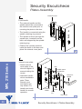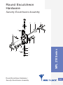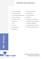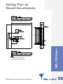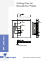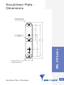
1
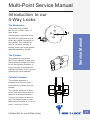
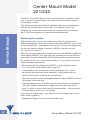
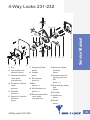
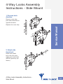
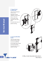
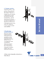
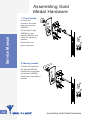
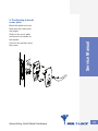
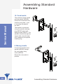
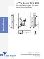
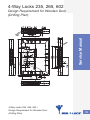
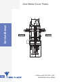
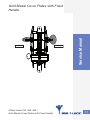
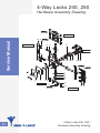
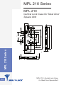
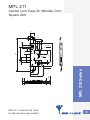
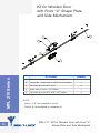
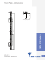
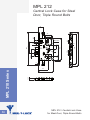
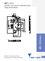
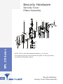
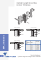
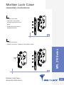
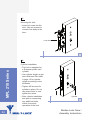
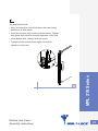
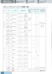
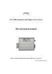
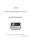
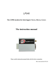
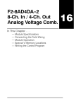
Multi-Point Locks Service Manual Multi-Point Service Manual........................................ 27 Introduction to our 4-Way Locks.................................... 27 Center Mount Model 221/222. .......................................... 28 4-Way Locks 231-232.......................................................... 29 4-Way Locks - Side Mount Lock Models 235, 265, 602, 240, 250. ........................................................................ 30 4-Way Locks Assembly Instructions - Side Mount... 31 Assembling Gold Medal Hardware. ............................... 34 Assembling Standard Hardware..................................... 36 4-Way Locks 235, 265 ....................................................... 38 Design Requirement for Steel Door (Punching Plan)........... 38 4-Way Locks 235, 265, 602. .............................................. 39 Design Requirement for Wooden Door (Drilling Plan).......... 39 Hardware Assembly Drawing - Standard Cover Plates......... 40 Hardware Assembly Drawing - Standard Cover Plates with Fixed Handle........................................................................ 42 Assembly Drawing - Standard Cover Plates......................... 44 Standard Cover Plates with Fixed Handle............................ 45 Hardware Assembly Drawing - Gold Medal Cover Plates..... 46 Hardware Assembly Drawing - Gold Medal Cover Plates with fixed Handle................................................................. 48 Gold Medal Cover Plates..................................................... 50 Gold Medal Cover Plates with Fixed Handle........................ 51 4-Way Locks 240, 250. ....................................................... 52 Hardware Assembly Drawing............................................... 52 MPL 210 Series..................................................................... 55 MPL 210.................................................................................. 55 Central Lock Case for Steel Door Square Bolt..................... 55 MPL 211. ................................................................................. 56 Central Lock Case for Wooden Door Square Bolt.................. 56 Kit for Wooden Doorwith Front “U” Shape Plate and Side Mechanism............................................................ 57 Front Plate - Dimensions...................................................... 58 MPL 212.................................................................................. 59 Central Lock Case for Steel Door, Triple Round Bolts.......... 59 MPL 213.................................................................................. 60 Central Lock Case for Wooden Door Triple Round Bolts...... 60 Security Hardware............................................................... 61 Security Cover Plates Assembly........................................... 61 Hardware & Accessories...................................................... 62 Cylinder Length According to Door Thickness...................... 63 Mortise Lock Case. ............................................................. 64 Assembly Instructions ......................................................... 64 Security Escutcheon ......................................................... 67 Plates Assembly................................................................... 67 Round EscutcheonHardware........................................... 68 Security Escutcheons Assembly........................................... 68 Hardware & Accessories...................................................... 69 Drilling Plan for Round Escutcheonsׁ. ............................ 70 Drilling Plan for Escutcheon Plates. ............................. 71 Escutcheon Plate - Dimensions...................................... 72 Multi-Point Service Manual Introduction to our 4-Way Locks The Mechanism A main (large) cogwheel drives the bolts into the frame as it is driven by a small cog wheel on the cylinder. The mechanical ratio is 1:4 which provides a locking power four times greater than that applied by the key. The Cylinder This mechanism requires a Mul‑T‑Lock cylinder of gear type with a minimum length of 66 mm to suit the cylinder protector. A longer cylinder is optional and requires extension of the cylinder protector by use of spacers. Service Manual This model, like all other Mul‑T‑Lock “4-Way” locks, is gear driven. Cylinder Protector The cylinder protector is mounted onto the lock case, to protect the cylinder from the outside. The cylinder protector is fitted to the lock case directly with no spacers, and should measure 33 mm from center to external end. If a longer length is used, spacers are required at 1 mm for every 1 mm over 33 mm. Introduction to our 4-Way Locks 27 Center Mount Model 221/222 The Mul‑T‑Lock Center Mount Lock is the world's first concealed “4-Way” lock. It can be found mounted in the center of the door cores, whether hollow metal or wood. Service Manual The following instructions will show exploded views for part identification, and will also provide some service tips – the complete “how to” for installing into a new door can be acquired via special factory training at Mul‑T‑Lock Technologies Ltd. in as specified headquarters. Replacing the cylinder With the door open, remove the inside cover plate (3), unscrew the 4 Phillips head screws on the four corners of the plate (MP046), and 3 of the 4 cup nuts (MP029) – pay attention! One of the 2 top cup nuts (depending on the door hand) is always a “dummy” (MP036), and will not come off – do not try to force it! After removing the inside cover, unscrew the two nuts (MP049) holding the inside spacer (MP023). The type may vary according to the year the lock was made. For most models this will allow the spacer to be removed and the cylinder to pull out, in some older models you may need to unscrew 2 additional sheet metal screws. •Be cautious with the rotating disk (MP025) – as the cylinder comes out – so it does not fall into the door or get lost. •It is advisable not to remove the outside cover plate (12) – as this will release the entire lock & bolt assembly – which should only be performed if the door is laid flat on a work bench. •Save and mount the small rectangular aluminum piece (MP037) from the old cylinder to the new one. •Hold the cylinder in the “0” position (this is where the key can be pulled out of the cylinder). Make sure it engages the lock case gear at this point. To verify, turn the lock to the fully locked position – the key should now be ready to come out of the cylinder. If you feel it is slightly away – you may correct by “jumping” one or more teeth of the cog wheel) •Replace the Spacer, the nuts, and the inside cover. 28 Center Mount Model 221/222 4-Way Locks 231-232 15 14 13 5 6 1 2 3 7 8 9 10 11 4 1 Key 2 Cover plate nuts MP029X3, MP036 3 Internal decorative cover plate (escutcheon) 4 Screws for internal cover MP046X4 5 Nuts M8 MP049X2 6 Spacer for cylinder protector 7 Supporting Plate MP038 8 Washer MP051 9 Bolt silencer MP027 X4 10Bolt MP028 X 4 11M6 threaded rod MP033 X 4 12External decorative cover plate (escutcheon) MP023 12 Service Manual 18 17 16 13External cylinder protector MP024 14Cylinder protector mounting screws M8 MP021 X 2 15Anti-drilling rotating disk MP025 16Cylinder 17Spatial nut MP037 18Screw MP052 4-Way Locks 231-232 29 4-Way Locks - Side Mount Lock Models 235, 265, 602, 240, 250 The side mount (on door edge) lock cases are available in many different models. The two main categories are: Service Manual •Auxiliary locks such as 230, 240, etc. that can be fitted to an existing door, without interfering with the door current latching mechanism/lock, that can remain in the door 30 •Primary locks that incorporates a latching mechanism & handles of various types such as 225, 235, 265, 602 etc. They are used as the door’s primary lock and other (single point) auxiliary locks can be added if needed (deadbolts etc…) The first and most obvious difference is the escutcheons (cover plates). The ones for the auxiliary locks are small, and the one for the primary locks are rectangular. For exact models and available finishes & colors, see the relevant pages in the Mul-T-Lock catalogue. All models of the latch incorporated locks can be found on various security doors using Mul-T-Lock 4-Way locks as the primary locks. Some door manufacturer are adding additional bolts that are driven by the lock vertical bolts – consult the relevant instruction by the door manufacturer prior to attempting any service work on those! 4-Way Locks - Side Mount Lock Models 235, 265, 602, 240, 250 4-Way Locks Assembly Instructions - Side Mount 1. Reverse latch direction Remove cover strip push and rotate latch to opposite direction. Service Manual Replace the cover strip. 2. Attach side (back) bolt Attach side (back) bolt to the lock case, make sure screw head (MP050) points up (as shown). 4-Way Locks Assembly Instructions Side Mount 31 3. Insert lock & side bolt Insert lock & side bolt into the door. Service Manual Using the screws (MP042) connect lock body to the door. On wooden doors install the rear face plate. On steel doors use a plastic bushing. 4. Top and bottom bolts Insert top and bottom bolt and connect with the screws (MP050). On wooden doors install the rear face plate. On steel doors use a plastic bushing. 32 4-Way Locks Assembly Instructions Side Mount Insert the cylinder in “zero” position. This is where the key can be pulled out of the cylinder – make sure it engages the lock case gear in this position (to verify, turn the lock to the fully locked position – the key should now be ready for removal from the cylinder. If you feel it is slightly out of alignment you may correct it by advancing one or more teeth of the cogwheel). Lock the cylinder with M5 screw (MP040). 6. Positioning cylinder protector Service Manual 5. Cylinder position Mount the cylinder protectors with the rotating disk and an appropriate number of spacers.Connect them using the screws (MP030). Do not over-tighten the screw nuts (MP042)! When the protectors are secure use the key to check that the mechanism is working properly, and if not, release the nut until it is. 4-Way Locks Assembly Instructions Side Mount 33 Assembling Gold Medal Hardware 7. Fixed handle Service Manual Connect the handle to the cover plate using screw (MP040). Put the two E-clips (MP048) on the spindle (MP005) and insert the spindle in position. Mount the cover plate in position. 8. Moving handle Connect the handle to the spindle (MP002) through the cover plate using screw (MP043). Mount the cover plate in position. 34 Assembling Gold Medal Hardware 9. Positioning internal cover plate Mount the plate and nuts. Note that the center nuts are longer. Connect the spindle using the screw. Assembling Gold Medal Hardware Service Manual Snap on the cover plate and mount the handle on the spindle. 35 Assembling Standard Hardware Service Manual 10. Fixed handle The external square handle and the spindle (MP008) should be connected to the outside cover plate – prior to mounting the plate to the door. The handle is connected using the spindle retaining ring (MP045) and 4 self taping screws (MP047). The spindle is driven through the square hole, from the back until stopped by the spindle retaining ring. 8. Moving handle Connect the handle to the spindle (MP002) through the cover plate using screw (MP043). Mount the cover plate in position. 36 Assembling Standard Hardware 12. Internal cover plate The internal cover plate is available in two different models: Standard plate – with decorative nuts. When using the first – adjust all nuts so that the screwdriver slots point in the same direction. When using the second – tighten all nuts, then snap on the decorative cover prior to mounting the inside handle Assembling Standard Hardware Service Manual Double plate – with concealed nuts. 37 4-Way Locks 235, 265 Service Manual Design Requirement for Steel Door (Punching Plan) 38 4-Way Locks 235, 265 / Design Requirement for Wooden Door (Drilling Plan) 4-Way Locks 235, 265, 602 Service Manual Design Requirement for Wooden Door (Drilling Plan) 4-Way Locks 235, 265, 602 / Design Requirement for Wooden Door (Drilling Plan) 39 Hardware Assembly Drawing Standard Cover Plates Service Manual UP 35 34 FRAME SIDE 33 32 28 29 30 31 EXTERIOR 36 37 20 21 22 23 24 25 26 27 38 10 11 12 13 14 15 1 2 3 4 5 6 7 8 9 16 17 INTERIOR 18 19 BOTTOM 40 4-Way Locks 235, 265, 602 / Hardware Assembly Drawing - Standard Cover Plates 2 Thumbturn retaining screw 3 Lever handle MP004 X2 4 Internal decorative cover plate (escutcheon ) 5 Cover plate nuts MP029 X6 6 Cover plate base 7 Nuts M8 MP049 X2 8 Internal cylinder protector MP021 9 Cylinder protector spacer, plastic 10 mm MP026 10Rod connecting screw 10/32 MP050 X3 11Bolt silencer MP027 X3 12Bolt MP028 X3 13Retaining pin MP035 X3 14Bolt cup, available as: hardened, stainless, or conical shape 15Wood door edge plate, 22mm or 25mm. For steel use bushing 16 MP020 X3 16Plastic bushing for edge of metal doors MP032 X3 17Screws #8 X 1 ¼” MP046 X28 18Strike plate for wood frame MP018 X3 19Strike plate for wood frame – optional with cup. MP019 X3 20Euro profile cylinder with gear. 21Cylinder protector Spacer MP023 22Anti-drilling rotating disk 25Plastic filler for holding screws in place MP022 26M6 threaded rod MP033 X6 27External cover plate 28Handle spindle MP002 X3 29Handle decorative cover MP006 30Lever handle internal cover 31Lever handle external cover 32Face plate 33Screw MP039 X2 34Strike plate fixing screw MP046 (=17) 35Strike plate MP025 23External cylinder protector MP024 24Cylinder protector mounting screws M8 MP021 X2 Service Manual 1 Thumbturn MP013 235,265 MP014 for 602 36M5 Screw for cylinder fixing MP036 37Nuts MP041 X2 38Handle fixing screw MP044 X2 MP031 X3 4-Way Locks 235, 265, 602 / Hardware Assembly Drawing - Standard Cover Plates 41 Service Manual Hardware Assembly Drawing - Standard Cover Plates with Fixed Handle UP 40 39 38 37 36 35 34 33 EXTERIOR FRAME SIDE 41 42 22 23 24 25 27 28 29 30 31 32 44 43 12 9 10 11 13 14 15 16 7 8 INTERIOR 1 42 2 3 4 5 6 17 18 19 BOTTOM 20 21 4-Way Locks 235, 265, 602 / Hardware Assembly Drawing - Standard Cover Plates with Fixed Handle MP004 5 Lever handle external cover 6 Internal decorative cover plate (escutcheon) 7 Cover plate Nuts MP029 X62 8 Cover plate base 9 Nuts M8 MP049 X2 10Internal Cylinder protector MP021 11Plastic filler for holding screws in place 10 mm MP026 12Rod connecting screw 10/32 X 10 MP050 X3 13Bolt silencer MP027 X3 14Bolt MP028 X3 15Retaining pin MP035 X3 16Bolt cup, available as: Hardened, stainless, or conical shaped 17Wood door edge plate, 22 mm or 25 mm. For steel use bushing 16 MP020 X3 18Plastic bushing for edge for metal doors MP032 X3 19Screws #8 X 1 ¼” MP046 X28 20Strike plate for wood frame MP018 X3 21Strike plate for wood frame – optional with cup. MP019 X3 22Euro profile cylinder with gear. 23Spacer for cylinder protector MP023 24Anti drilling rotating disk MP025 25External cylinder protector MP024 26Cylinder protector mounting screws M8 MP021 X2 27M6 threaded rod MP033 X6 28Plastic filler for holding screws in place MP022 29Static cover plate base 30Fixed handle internal cover 31Fixed handle MP010 32Fixed handle external cover 33Spindle Retaining Ring MP045 34Spindle MP008 35Ring MP011 36Screw MP47 X4 37Face plate 38Screw MP039X2 39Strike plate fixing screw Service Manual 1 Thumbturn 2 Thumbturn retaining screw 3 Lever handle internal cover 4 Lever handle MP046 (=17) 40Strike plate MP013 235,265 MP014 for 602 41M5 Screw for cylinder fixing MP040 42Nuts MP041 X2 43Handle decorative cover MP006 X2 44Handle fixing screw MP044 MP031 X3 4-Way Locks 235, 265, 602 / Hardware Assembly Drawing - Standard Cover Plates with Fixed Handle 43 Service Manual Assembly Drawing - Standard Cover Plates 44 INTERIOR EXTERIOR 4-Way Locks 235, 265, 602 / Assembly Drawing - Standard Cover Plates INTERIOR 4-Way Locks 235, 265, 602 / Standard Cover Plates with Fixed Handle EXTERIOR Service Manual Standard Cover Plates with Fixed Handle 45 Hardware Assembly Drawing Gold Medal Cover Plates 33 32 25 24 Service Manual 29 28 46 26 27 31 30 35 34 20 21 22 23 10 9 11 12 78 5 1 2 3 4 13 14 6 16 15 17 18 19 4-Way Locks 235, 265, 602 / Hardware Assembly Drawing - Gold Medal Cover Plates 2 Thumbturn retaining screw 3 Lever handle MP001 4 Internal decorative cover plate (escutcheon) 5 Cover plate Nuts MP029 X6 6 Cover plate base 7 Nuts M8 MP049 X2 8 Internal Cylinder protector MP021 9 Cylinder protector spacer Plastic 10mm MP026 10Rod connecting screw MP050 X6 11Bolt silencer MP027 X3 12Bolt MP028 X3 13Retaining pin MP035 X3 14Bolt cup, available as: Hardened, stainless, or conical shaped MP031 X3 15Wood door edge plate, 22mm or 25mm. For steel use bushing 16 MP020 X3 16Plastic bushing for edge of metal doors MP032 X3 17Screws #8 X 1 ¼” MP046 X28 18Strike plate for wood frame MP018 19Strike plate for wood frame – optional with cup. MP019 20Euro profile cylinder with gear. 21Cylinder protector spacer MP023 22Anti drilling rotating disk MP025 24External handle fixing screw MP012 25Handle spindle MP002 26External cylinder protector MP024 27Cylinder protector mounting screws M8 MP021 28Face plate 29Screw MP039 X2 30Nuts MP041 X 2 31M5 Screw for cylinder fixing Service Manual 1 Thumbturn MP040 32Strike plate fixing screw MP046 (=17) 33Strike plate MP013 235,265 MP014 for 602 34Handle fixing screw MP043 35Handle decorative cover 23M6 threaded rod MP006 X2 MP033 X6 4-Way Locks 235, 265, 602 / Hardware Assembly Drawing - Gold Medal Cover Plates 47 Hardware Assembly Drawing Gold Medal Cover Plates with Fixed Handle 24 UP 36 35 32 31 Service Manual FRAME SIDE 48 30 27 26 25 EXTERIOR 28 29 33 34 20 21 22 23 10 38 37 11 12 13 14 5 1 2 3 4 6 7 8 INTERIOR 9 15 16 17 BOTTOM 18 19 4-Way Locks 235, 265, 602 / Hardware Assembly Drawing - Gold Medal Cover Plates with Fixed Handle 2 Thumbturn retaining screw 3 Lever handle MP001 4 Internal decorative cover plate (escutcheon) 5 Cover plate Nuts MP029X6 6 Cover plate base 7 Nuts M8 MP049X2 8 Internal Cylinder protector MP021 9 Plastic Spacer for cylinder protector 10 mm MP026 10Rod connecting screw MP050 X3 11Bolt silencer MP027 X 3 12Bolt 15Wood door edge plate, 22mm or 25mm. For steel use bushing 16 MP020 X 3 16Plastic bushing for edge of metal doors MP032 17Screws #8 X 1 ¼” MP046 X 28 18Strike plate for wood frame MP018 19Strike plate for wood frame – optional with cup. MP019 20Euro profile cylinder with gear. 21Spacer for cylinder protector MP023 22Anti drilling rotating disk MP025 23M6 threaded rod MP028 X 3 MP033 X 6 13Retaining pin 24Fixed handle MP035 X 3 14Bolt cup, available as: Hardened, stainless, or conical shaped 26Screw for Fixed handle adaptor MP042 X4 27Spindle retaining ring MP048 X 2 28External cylinder protector MP024 29Cylinder protector mounting screws M8 MP021 X 2 30Spindle MP005 31Face plate 32Screw MP039 X 2 33M5 Screw for cylinder fixing MP040 34Nuts MP041 X2 35Strike plate fixing screw MP046 (=17) 36Strike plate MP013 235,265 MP014 for 602 MP007 25Fixed handle adaptor MP011 Service Manual 1 Thumbturn 37Handle decorative cover 38Handle fixing screw MP031 X 3 4-Way Locks 235, 265, 602 / Hardware Assembly Drawing - Gold Medal Cover Plates with Fixed Handle MP043 X 2 49 Service Manual Gold Medal Cover Plates 50 INTERIOR EXTERIOR 4-Way Locks 235, 265, 602 / Gold Medal Cover Plates INTERIOR 4-Way Locks 235, 265, 602 / Gold Medal Cover Plates with Fixed Handle EXTERIOR Service Manual Gold Medal Cover Plates with Fixed Handle 51 4-Way Locks 240, 250 Hardware Assembly Drawing UP Service Manual 26 25 FRAME SIDE 24 23 22 EXTERIOR 27 28 16 17 1 18 19 20 21 6 7 8 1 2 3 9 10 4 5 INTERIOR 12 11 14 15 13 BOTTOM 52 4-Way Locks 240, 250 / Hardware Assembly Drawing MP029 X 4 2 Internal decorative cover plate (escutcheon) 3 Cover plate base 4 Nuts M8 MP049 X 2 5 Plastic Spacer for cylinder protector 10mm MP026 X 4 6 Rod connecting screw MP050 X 4 7 Bolt silencer MP027 X 3 8 Bolt MP028 X 3 9 Retaining pin MP035 X 3 10Bolt cup, available as: Hardened, stainless, or conical shaped MP031 X 3 11Wood door edge plate, 22mm or 25mm. For steel use bushing 16 MP020 X 3 12Plastic bushing for edge of metal doors MP023 X 3 13Screws MP046 X 28 14Strike plate for wood frame MP018 X 3 15Strike plate for wood frame – optional with cup. MP019 X 3 16Euro profile cylinder with gear. 17Spacer for cylinder protector MP023 18External cylinder protector MP024 4-Way Locks 240, 250 / Hardware Assembly Drawing 19Cylinder protector mounting screws M8 MP021 X 2 20M6 threaded rod MP033 X 6 21External decorative cover plate (escutcheon) + base 22Anti drilling rotating disk MP025 23Face plate 24Screw MP039 X 2 25Strike plate fixing screw Service Manual 1 Cover plate Nuts MP046 (=24) 26Strike plate MP015 27M5 Screw for cylinder fixing MP040 28Nuts MP041 X 2 53 MPL 210 Series MPL 210 Central Lock Case for Steel Door Square Bolt TYP2 228 250 25 250 38 54 22 MPL 210 Series TYP2 MPL 210 / Central Lock Case for Steel Door Square Bolt MPL 211 Central Lock Case for Wooden Door Square Bolt 31 3 9.5 38 24.5 8 Ø 8 TYP2 32 96 13 170 90 241 28 Ø14 8 36 38 62 MPL 211 / Central Lock Case for Wooden Door Square Bolt 16 15 7.5 19 MAX 96 MPL 210 Series Ø10.5 TYP2 55 Kit for Wooden Door with Front “U” Shape Plate and Side Mechanism. 2 4 5 3 1 MPL 210 Series Kit Content 56 Quantity 1 MPL 211 lock with front plate guide adaptors 1 2 Front plate - length 1850 mm with side mechanism 1 3 Flat head tap screw ST4.2x9.5 4 4 Strike plate for frame ( OPTIONAL) 1 5 Flat head tap screw ST4.2X38 ( OPTIONAL) 4 NOTE: • Parts 1, 2 & 3 are supplied in one kit. • Parts 4 & 5 are supplied in a separate kit. MPL 211 / Kit for Wooden Door with Front “U” Shape Plate and Side Mechanism Front Plate - Dimensions 24 24 2 6 20 10.5 1855 ± 1 95 62.5 Front plate profile 20 MPL 211 / Front Plate - Dimensions MPL 210 Series 95 755 665 36.5 745 8 57 MPL 212 Central Lock Case for Steel Door, Triple Round Bolts 34 38 Ø8 TYP2 24.5 24.5 8 13 15.8 260 40 170 38 29 52.7 238 32 Ø14 90 260 96 25 Ø10.5 TYP2 3 22 58 99 12.7 MPL 210 Series 65 MPL 212 / Central Lock Case for Steel Door, Triple Round Bolts MPL 213 Central Lock Case for Wooden Door Triple Round Bolts 31 3 9.5 38 24.5 8 Ø8 TYP2 Ø14 170 32 28 90 241 96 16 29 52.7 38 62 12.7 96 MPL 213 / Central Lock Case for Wooden Door Triple Round Bolts MPL 210 Series Ø10.5 TYP2 59 Security Hardware Security Cover Plates Assembly 3 21 7 9 14 12 4 5 6 8 13 10 11 18 17 16 MPL 210 Series 15 60 1 2 20 19 NOTE: Can be used with standard hardware. (cc = 90 mm) For maximum security we recommend using Mul-T-Lock high security escutcheons (EN grade 3 and 4). Security Hardware / Security Cover Plates Assembly Hardware & Accessories 1. External shield with handle 12. Handle decorative cover 2. Cover plate 13. Screw for handle fixing 3. Spindle 14. Internal handle 4. Internal shield reinforcement 15. Plastic bushing 5. Cover plate nut 16. Bolt cup 6. Internal plastic guide insert 17. Bolt 7. Handle return mechanism clip 18. Bolt silencer 8. Screw M6x45 19. Retaining pin 9. Handle return mechanism 20. Euro profile cylinder with cam 10. Internal shield 21. M5 Screw for cylinder fixing MPL 210 Series 11. Cover cap screw Security Hardware / Hardware & Accessories 61 Cylinder Length According to Door Thickness DOOR THICKNESS DOOR THICKNESS MPL 210 Series OUTSIDE X X INSIDE LOCK LOCK DOOR DOOR IN - SWING DOOR DOOR THICKNESS OUTSIDE X INSIDE LOCK DOOR OUT - SWING DOOR 62 OUTSIDE INSIDE Door X Thickness (mm) (mm) Cylinder 40 45 45 45 45 45 66-33/33 71-33/38 70-35/35 71-33/38 75-35/40 76-43/33 20 18-19 20-22 23-25 26-27 28-30 Security Hardware / Cylinder Length According to Door Thickness Mortise Lock Case Assembly Instructions 1 Reversing the latch: • Unscrew 4 front plate screws and remove front plate. • Push and rotate latch to desired direction. 1 2 • Attach front plate. MPL 210 Series • Attach front plate. Tighten 4 front plate screws. 2 Mortise Lock Case / Assembly Instructions 63 3 Mounting the lock: • Insert lock case into the door. Use two screws to connect lock body to the door. Lock case 3 4 MPL 210 Series Cylinder installation: 64 • This lock is operated by a European profile cam cylinder • Use cylinder length as per door thickness! See table in page 10 for cylinder length according to door thickness. • Tighten M5 screw to fix cylinder in place. Do not use power tools or over tighten the screw. • After cylinder installation and prior to connecting any additional bolts, check for smooth operation of the lock. M5 Screw Cylinder 4 Mortise Lock Case / Assembly Instructions 5 Top and bottom bolts: • Note: this operation should be done with door being laid flat on a work bench. • Insert the top bolt and connect with the screw. Tighten bolt screw and check for smooth operation of the lock. • Insert bottom bolt, connect with the screw. 5 Mortise Lock Case / Assembly Instructions MPL 210 Series • Tighten bolt screw and check again for smooth operation of the lock. 65 Security Escutcheon Plates Assembly External cover 6 Fixed handle • The external handle and the spindle should be connected to the outside cover plate prior to mounting the plate to the door. • The handle is connected using the spindle retaining ring screws. • The spindle is driven through the square hole, inserted from the back until stopped by the spindle retaining ring. Spindle • Position the cylinder protector inside the holes in the door and place the external cover plate. 6 7 MPL 210 Series Internal cover plate 66 • Attach internal cover plate to the door and tighten 3 screws holding the covers. • Assemble handle return mechanism parts. Place internal cover and tighten two cup screws. Fix handle and check handle for smooth operation. Clip Handle return mechanism Screw for handle Internal shield Insert Cover nut Cap screw Security Escutcheon / Plates Assembly 7 Round Escutcheon Hardware Security Escutcheons Assembly 12 18 19 13 14 17 15 4 3 6 7 1 2 10 5 8 9 Round Escutcheon Hardware / Security Escutcheons Assembly MPL 210 Series 16 11 67 Hardware & Accessories 1. External lever handle 11. Internal lever handle 2. External escutcheon 12. Handle spindle 3. Euro profile cylinder with cam 13. Connecting screw 4. Internal escutcheon 14. MPL lock 5. Escutcheon screw 15. M5 Screw for cylinder fixing 6. Bolt silencer 16. External handle security cover 7. Bolt 17. Screw for handle fixing 8. Bolt cup 18. Internal handle security cover 9. Plastic bushing 19. Handle security cover screw MPL 210 Series 10. Retaining pi 68 Round Escutcheon Hardware / Hardware & Accessories Drilling Plan for Round Escutcheons ׁ 205 209 228 251 * Recommended Dimension Drilling Plan for Round Escutcheonsׁ MPL 210 Series 69 Drilling Plan for Escutcheon Plates 205 MPL 210 Series 70 * Recommended Dimension Drilling Plan for Escutcheon Plates Escutcheon Plate Dimensions 68 APLICABLE WITH M8 SCREWS AND NUTS APLICABLE WITH M8 SCREWS AND NUTS 45 Escutcheon Plate - Dimensions 230 MPL 210 Series 46 90 204 32 APLICABLE WITH M6 SCREW 71 www.mul-t-lock.com With its readiness to rapidly respond to any challenge, Mul-T-Lock ensures peace of mind by delivering comprehensive, customized, top security cylinder locking solutions and services worldwide. ASSA ABLOY is the global leader in door opening solutions, dedicated to satisfying end-user needs for security, safety and convenience. The Mul-T-lock name and Muscleman Logo, and any other name, mark or logo used by Mul-T-Lock and marked by an ® or ™ sign, are registered/pending trademarks of Mul-T-Lock Ltd. in various countries. Mul-T-Lock reserves the right to make any product improvements or modifications without prior notice. © Mul-T-Lock Technologies Ltd. 2007 Cat. No. 98101786-B An ASSA ABLOY Group brand