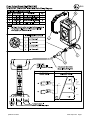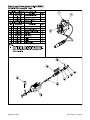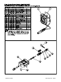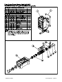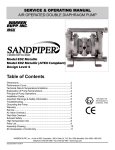
1
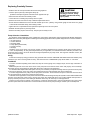
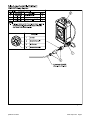
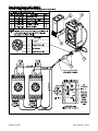
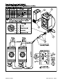
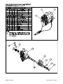
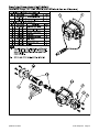
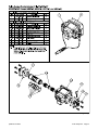
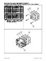
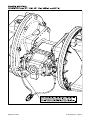
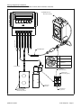
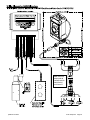
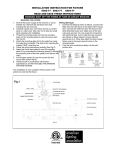
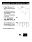
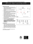
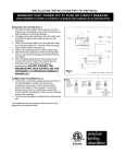
SERVICE AND OPERATING MANUAL
PULSE OUTPUT KIT
Design Level 5
WARNING!
Pulse Output Interface
Pulse Output Interface Kits cannot be
used if pump is to be submerged.
The Pulse Output Interface Kits are designed for easy field installation. The Kits are also available factory-installed on new
pumps. The Pulse Output Interface Kit mounts on the pump and provides electrical pulses to operate the Warren Rupp Batch
Control/Stroke Counter, or a customer-supplied control. The unit creates an electrical interface between the control and the
air-powered pump. Pulse Output Kits can be purchased separately, for use in applications where a process controller is already
present in a system. This provides a direct interface with the pump and the customer’s system.
Operation
Each pump stroke generates a signal through a proximity sensor (PNP) on either end of the air valve. As the air valve reciprocates
back and forth during pump operation, targets on either end of the spool activate their respective proximity sensors. Each sensor
signals the control to register one count on the stroke counter / batch control unit. This method provides a positive signal for
every pump stroke, but with very few wearing parts.
Connecting a Factory-Installed Kit
Pulse Interface Kits are available factory-installed on new SANDPIPER and MARATHON diaphragm pumps. When installing,
always refer to the service manual for pump installation and operation recommendations. After installing the pump, connect
the interface to the control source. To connect the interface to the control source:
•
Install input cable according to the wiring diagram for your specific interface kit.
•
Connect to Warren Rupp Batch Controller or existing system control.
Field Installation of Kit
Before adding an interface kit to an existing SANDPIPER or MARATHON pump, verify the compatibility
of the pump model, kit number and voltage being used. A complete listing appears on page 3
Field Installation
•
Remove the main air valve body assembly and gasket.
•
Install the Pulse Output Kit,and pulse output pump adapter kit tighten and torque the screws according to the pump
service manual instructions.
•
Refer to the applicable wiring diagram when connecting to control source.
Warren Rupp, Inc. • A Unit of IDEX Corporation • 800 N. Main St., Mansfield, Ohio 44902 USA
Telephone (419) 524-8388 • Fax (419) 522-7867 • www.warrenrupp.com
pokdl5sm-rev0614
©Copyright 2014 Warren Rupp, Inc. All rights reserved.
Replacing Proximity Sensors
• Shift the main air valve spool toward the sensor being replaced.
• Lock the spool in place by inserting the safety clip
(included in the kit) through the small hole of the opposite end cap.
• Disconnect the sensors from terminal junction.
CAUTION!
Safety clip locks pump for
security or service. Pump
will NOT operate with safety
clip in place.
• Loosen the hex nut holding the proximity sensor in place.
• Remove the sensor from the end cap. Install the replacement sensor.
• Set the clearance between the sensor and the actuator pin to .015" (.38mm), using a feeler gauge or shim stock. The gauge
or shim stock should slide freely, while making contact.
• Tighten the hex nut provided with the replacement proximity sensor to lock in place.
• Reattach terminal juction to proximity sensor
• Remove the safety clip from the end cap. The pump is now ready for use.
Pump Selection & Installation
Air-operated, double diaphragm pumps (AODD) are semi-positive displacement pumps designed with flexible diaphragms.
AODD have successfully been applied in metering and batching applications where system design allows for minimal variation of:
• Air Inlet Pressure
• Suction Head/Lift
• Discharge Head
• Pump Speed (Stroke Rate)
• Product Viscosity
• NPSH(a)
Variations of any of the above can result in variable, volumetric displacement per pumping stroke which normally holds to
+/- 1% to 3% repeatability. To verify actual displacement in your application, it is essential to follow a calibration procedure. This
allows the batch control to be set for the actual average displacement per pump stroke. The larger the calibration volume, the
more precise the average.
Sizing
Follow the normal pump sizing procedures using published data. DO NOT OVERSIZE THE PUMP. Select the smallest pump
suitable for your use to ensure greater accuracy. The batch size from a SANDPIPER pump will be within +/- one stroke.
Installation
To ensure consistent repeating of the batch size, keep the suction piping short, straight, simple, and as large a diameter as
is practical.
Differential pressure across the check valves of the pump will insure that the check valves seat properly and consistently.
Discharge pressure must always be greater than the suction pressure in the application.
For consistent fluid displacement and system accuracy it is mandatory to keep the discharge line full of product from the pump
to the point of discharge. A one-way check valve installed in the end of the discharge line will accomplish this.
In suction lift applications the pump must be kept primed at all times. Suction lift must be kept to a minimum and a foot valve
may be required in the suction line to keep the pump primed.
In flooded suction applications a back pressure device located in the discharge line may be required to insure sufficient differential
pressure across the pump check valves. The one-way check valve mentioned above may provide sufficient back pressure to
properly seat the pump check valves although additional means may be necessary in some applications.
Install an air line pressure regulator. This ensures a constant air pressure feed to the pump eliminating low to peak usage
pressure spikes which will increase and or decrease the stroke rate of the pump resulting in variable (non-controlled) flow.
pokdl5sm-rev0614
Pulse Output Kit Page 2
IMPORTANT
Table 1
Pulse Output Kits
Pulse Output Interface Kit Selection Instructions
System Voltage
Step 1
Step 2
Step 3
Note:
Determine the required system voltage and
then chose one of the three Pulse Output
Kits from Table 1. Each kit will include
Proximity Sensor, Field Connector, and
Terminal Junction
Determine the pump model being used and
then choose the required Pulse Output
Adapter Kit from Table 2. Each Kit include
all parts required for field installation of kit,
which may include Air Valve Assembly,
Gaskets, Spacer Plate, and/or Hardware
Order the combination of the Pulse Output
Kit and the Pulse Output Adapter Kit
together to successfully field install a Pulse
Output Interface.
When ordering a pump with a factory
installed Pulse Output interface refer to
Pump and Assecories Price Sheet for
proper pump model number
Standard 110VAC
475-244-002 Refer to Page 5
Standard 220VAC
Intrinsically Safe 10-30VDC, 110VAC, & 220VAC
475-244-002 Refer to Page 6
475-244-003 Refer to Page 7
Table 2
Pulse Output Adapter Kits
Pump Class
Size
1/4"
Standard Duty
Non-Metallic
Pump Model
PB1/4-A / MP01P
Kit Number
Comment
475-245-001 Refer to Page 8
1/2"
S05 / M05
475-245-002 Refer to Page 9
3/4"
S07 / M07
475-245-002 Refer to Page 9
1"
S10 / M10
475-245-002 Refer to Page 9
S1F / M1F
475-245-003 Refer to Page 10
1 1/2"
S15 / M15
475-245-003 Refer to Page 10
2"
3"
S20 / M20
S30 / M30
475-245-003 Refer to Page 10
475-245-003 Refer to Page 10
1/2"
S05 / M05
475-245-002 Refer to Page 9
Standard Duty
Metallic
1"
S1F / M1F
475-245-003 Refer to Page 10
1 1/2"
S15 / M15
475-245-003 Refer to Page 10
2"
3"
S20 / M20
S30 / M30
475-245-003 Refer to Page 10
475-245-003 Refer to Page 10
Pump Class
Size
1 1/2"
Note 1
Heavy Duty Ball
Heavy Duty Flap
HDB1 1/2 / HDB40
HDB2
3"
4"
HDB3
1"
HDF1 / HDF25
3"
4"
1"
Containment Duty
Pump Model
1 1/2"
HDF2
2"
Special Duty
3"
4"
Kit Number
Comment
475-245-004 Refer to Page 11
Aluminum
475-245-005 Refer to Page 12
Cast Iron
475-245-006 Refer to Page 13
Aluminum
475-245-005 Refer to Page 12
Cast Iron
475-245-006 Refer to Page 13
475-245-007 Refer to Page 14
475-245-007 Refer to Page 14
HDB4
475-245-004 Refer to Page 11
Aluminum
475-245-005 Refer to Page 12
Cast Iron
475-245-006 Refer to Page 13
HDF3-M
475-245-007 Refer to Page 14
HDF3-A
475-245-008 Refer to Page 15
HDF4-M
475-245-007 Refer to Page 14
475-245-008 Refer to Page 15
HDF4-A
ST1 / ST25
Refer to Note 1
ET1-M / MP04D
Refer to Note 1
ET1 1/2-SM / MP05D
Refer to Note 1
ET1 1/2-M / MP07D
ST1 1/2 / ST40
2"
3"
Mid-Section
SB1 / SB25
2"
2"
pokdl5sm-rev0614
Comment
475-244-001 Refer to Page 4
1"
Assembly Notes
Pulse Output Adapter Kits do not not
require an Adapter Kit to install Pulse
Output kits to that particular pump. Order
only the appropriate Pulse Output Kit (See
Table 1)
Kit Number
Standard 10-30VDC
ET2-M / MP08D
ET3-M / MP12D
Refer to Note 1
475-245-009 Refer to Page 15
Refer to Note 1
Refer to Note 1
MSB2
475-245-005 Refer to Page 12
MSA2
475-245-005 Refer to Page 12
W09-2
Refer to Note 1
W09-3
Refer to Note 1
W15-3
Refer to Note 1
Refer to Note 1
W15-4
Pulse Output Kit Page 3
pokdl5sm-rev0614
Pulse Output Kit Page 4
pokdl5sm-rev0614
Pulse Output Kit Page 5
pokdl5sm-rev0614
Pulse Output Kit Page 6
See page 2
II2GD
for ATEX ratings.
II
I
4
7
BU
1
1
YE/RD
-4
10
BN
1
1
NAMUR
< 250 VAC/
30 VDC
< 2A
< 500 VA/60 W
8
BU
5
+8,2 V
+1
2
YE/RD
-5
2
9
BN
2
2
NAMUR
+2
11
POWER
pokdl5sm-rev0614
(9) (7)
(10)
3
(12) (11) (8)
X
Pwr
GN
12
Pulse Output Kit Page 7
pokdl5sm-rev0614
Pulse Output Kit Page 8
pokdl5sm-rev0614
Pulse Output Kit Page 9
165-098-147
pokdl5sm-rev0614
Pulse Output Kit Page 10
HDF1 & SB1
pokdl5sm-rev0614
Pulse Output Kit Page 11
1-C
pokdl5sm-rev0614
Pulse Output Kit Page 12
pokdl5sm-rev0614
Pulse Output Kit Page 13
pokdl5sm-rev0614
Pulse Output Kit Page 14
pokdl5sm-rev0614
Pulse Output Kit Page 15
pokdl5sm-rev0614
Pulse Output Kit Page 16
Wiring Diagram for Interface
with 249-006-000 Batch Control / Stroke Counter (Non-Hazardous Location)
Stroke counter/Batch Control
DIGIT
SELECT
PRESET
COUNT
TOTAL
COUNT
START
INCREASE
DIGIT
RESET
SandPIPER Air Valve
Mounted to Pump
STOP
WARREN RUPP PUMP CONTROLS
CHASSIS GROUND
GROUND
STOP SWITCH
24VDC
PROXIMITY SENSOR INPUT(S)
START SWITCH
100-120VAC
100-240VAC
COMMON GROUND
RELAY OUTPUT (+)
NEUTRAL
POWER 100-240VAC
RELAY OUTPUT COMMON
IDEX CORPORATION
#22 AWG Cable
Power Input
1
(+) Common
2
Output Channel #1
3
(-) Ground
4
Output Channel #2
Terminal #1
Neutral (Positive)
Terminal #2
Power (Negative)
1
2
Solenoid
Air Valve
Customer Supplied
Remote Control
Momentary Switch
pokdl5sm-rev0614
3rd Terminal
for ground
Pulse Output Kit Page 17
Note: Switch the
output mode to
normally open for
both channel 1
and channel 2
(12) (11) (7)
pokdl5sm-rev0614
(9) (8)
(10)
Pulse Output Kit Page 18