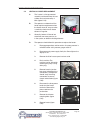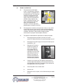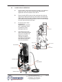
1
I.O.M. #083 1/08
INSTRUCTION MANUAL
• INSTALLATION • OPERATION • MAINTENANCE
Covers Models with ‘VE’ Series Instrument.
ADVANTAGE ENGINEERING, INC.
525 East Stop 18 Road Greenwood, IN 46142
317-887-0729 fax: 317-881-1277
Service Department fax: 317-885-8683
www.AdvantageEngineering.com
e-mail: [email protected]
INSTRUCTION MANUAL
SENTRA ‘SK’
‘VE’ SERIES INSTRUMENT
COVERING
INSTALLATION
OPERATION
MAINTENANCE
ADVANTAGE ENGINEERING, INC. 525 East Stop 18 Road Greenwood, IN 46142
317-887-0729 fax: 317-881-1277 Service Department fax: 317-885-8683
www.AdvantageEngineering.com e-mail: [email protected]
Temperature Control Units : Sentra with ‘VE’ Series Instrument
TABLE OF CONTENTS
SENTRA QUICK START-UP GUIDE
SENTRA “QUICK” TROUBLESHOOTING GUIDE
6
7
1.0
9
10
10
10
11
GENERAL
1.1
1.2
1.3
1.4
Safety
Efficiency
Typical Label Placement
Component placement
2.0
INSTALLATION
2.1
General
2.2
To and from process connections
2.3
Water supply connection
2.4
Drain connection
2.5
Electrical connection
13
14
14
15
15
16
3.0
START UP SEQUENCE
3.1
General
3.2
System fill/operations procedure
3.3
Instrument operation
3.4
Shut down/disconnect sequence
19
20
20
25
30
4.0
TROUBLESHOOTING
4.1
Unit will not start (Power light off)
4.2
Unit will not start (Power light on)
4.3
Unit stops
4.4
Unit overheats
4.5
Unit underheats
4.6
Pressure relief valve leaks
4.7
Cooling valve fault
33
34
34
34
35
36
37
38
5.0
MAINTENANCE
5.1
Pump seal replacement
5.2
Heating cylinder replacement
5.3
PVTTM cooling valve service
5.4
Probe calibration
5.5
Voltage changeover
5.6
Sensor probe service
5.7
Pressure switch service
5.8
Instrument service
5.9
Celsius temperature display
35
36
39
41
43
45
47
49
50
52
6.0
SENTRA COMPONENTS
6.1
Mechanical system
6.2
Electrical system
53
54
56
ADVANTAGE ENGINEERING, INC.
525 East Stop 18 Road Greenwood, Indiana 46142
317-887-0729 Fax: 317-881-1277
Service Department Fax: 317-885-8683
www.AdvantageEngineering.com
Page: 4
Temperature Control Units : Sentra with ‘VE’ Series Instrument
7.0
RELATED DRAWINGS
7.1
Sentra physical
7.2
Sentra electrical
7.3
Sentra circuit schematic
7.4
Sentra regulator/bypass installation
7.5
Sentra dual zone dolly
7.6
Sentra stacking rack
59
60
61
62
63
64
65
8.0
APPENDIX
8.1
8.2
8.3
8.4
8.5
8.6
8.7
8.8
67
68
69
70
71
72
73
74
75
Specifications
Sentra Model # and suffix coding
Interpretation of process pressure gauges
Mold purge operation
Closed Circuit Operation
Sentra AS5 pump parts list - 1/2 HP to 1 HP
Sentra AS5 pump parts list - 1 1/2 HP to 3 HP
Sentra parts list - LE instrument
ADVANTAGE ENGINEERING, INC.
525 East Stop 18 Road Greenwood, Indiana 46142
317-887-0729 Fax: 317-881-1277
Service Department Fax: 317-885-8683
www.AdvantageEngineering.com
Page: 5
Temperature Control Units : Sentra with ‘VE’ Series Instrument
SENTRA 'QUICK' START-UP GUIDE
INSTALLED TO CORRECT
ELECTRICAL SUPPLY?
ELECTRICAL SUPPLY
LISTED ON DATA TAG
...
BE CERTAIN UNIT IS INSTALLED
TO PROPER ELECTRICAL SUPPLY
NO
'TO PROCESS' TO 'WATER IN' ON
PROCESS MANIFOLD
...
'FROM PROCESS' TO 'WATER OUT'
ON PROCESS MANIFOLD
NO
WATER SUPPLY PRESSURE MUST BE
OVER 15 PSI FOR UNIT TO START
NO
CONNECT DRAIN LINE TO PROPER
RETURN SYSTEM
NO
CHECK DISCONNECT FUSE OR
TRANSFORMER FUSE
YES
NO
UNIT INSTALLED TO
PROCESS CORRECTLY?
YES
WATER SUPPLY OPEN AND
PRESSURE ADEQUATE?
YES
DRAIN LINE CORRECTLY
INSTALLED?
YES
ENGAGE POWER SUPPLY...
'POWER' LIGHT ON?
YES
TURN UNIT 'ON' AND
SELECT SETPOINT
ADVANTAGE ENGINEERING, INC.
525 East Stop 18 Road Greenwood, Indiana 46142
317-887-0729 Fax: 317-881-1277
Service Department Fax: 317-885-8683
www.AdvantageEngineering.com
Page: 6
Temperature Control Units : Sentra with ‘VE’ Series Instrument
SENTRA 'QUICK' TROUBLESHOOTING GUIDE
SENTRA WILL NOT START
"POWER" LIGHT ON?
MAIN POWER SUPPLY
"ON"?
YES
REPLACE TRANSFORMER
FUSE
YES
REPLACE TRANSFORMER
FUSE
NO
NO
WATER SUPPLY
PRESSURE LOW?
YES
PRESSURE SWITCH OPEN
SUPPLY UNIT WITH 15 PSI
YES
RESET OVERLOADS
ADJUST PROCESS FLOW
YES
TEMPERATURE OVER 256
ALLOW UNIT TO COOL
ENGAGE POWER
NO
YES
MOTOR OVERLOAD
RELAY OPEN?
NO
HIGH TEMP LIMIT
SWITCH OPEN?
NO
INSTRUMENT DEFECTIVE
REPLACE
SENTRA STOPS
"POWER" LIGHT ON?
MAIN POWER SUPPLY
"ON"?
YES
NO
NO
WATER SUPPLY
PRESSURE LOW?
YES
PRESSURE SWITCH OPEN
SUPPLY UNIT WITH 20 PSI
YES
RESET OVERLOADS
ADJUST PROCESS FLOW
YES
TEMPERATURE OVER 256
ALLOW UNIT TO COOL
YES
WATER SUPPLY PRESSURE MUST BE
SUFFICIENT FOR OPERATING TEMPERATURE
ENGAGE POWER
NO
MOTOR OVERLOAD
RELAY OPEN?
NO
HIGH TEMP LIMIT
SWITCH OPEN?
NO
INSTRUMENT DEFECTIVE
REPLACE
SENTRA OVERHEATS
INADEQUATE WATER
SUPPLY PRESSRE?
NO
AVT COOLING VALVE
DEFECTIVE?
CHECK VALVE WIRE
HARNESS
OR
CLEAN/REPLACE
BALL VALVE ASSEMBLY
OR
REPLACE MOTOR/GEARBOX
ASSEMBLY
YES
OPEN23 CLOSED
DRAIN LINE VALVE
OR
REDUCE HIGH DRAIN
LINE PRESSURE
YES
CHECK FOR A CLOSED
PROCESS VALVE
OR
KINKED HOSE OR
OR
EXCESSIVE PIPE FITTINGS
BLOCKED WATER CHANNEL
IN TOOLING OR MOLD
YES
CHECK FOR WATER IN
PROBE CONNECTION
OR
YES
CHECK FOR A DEFECTIVE
AVT COOLING VALVE
OR
LEAKING WATER PRESSURE
RELIEF VALVE
DETERMINE IF UNIT
CAPACITY TOO LOW
NO
YES
DRAIN LINE
OBSTRUCTED?
NO
LOW PROCESS
FLOW RATE?
NO
CONTROL PROBE
DEFECTIVE?
REPLACE PROBE
NO
INSTRUMENT DEFECTIVE
REPLACE
SENTRA UNDERHEATS
PROCESS WATER
LEAKAGE?
NO
HEATER ELEMENT
DEFECTIVE?
YES
REPLACE HEATER
NO
HEAT LOSS?
CHECK FOR EXCESSIVE
UNIT RADIATION
OR
YES
CHECK FOR WATER IN
PROBE CONNECTION
OR
NO
YES
CONTROL PROBE
DEFECTIVE?
REPLACE PROBE
NO
INSTRUMENT DEFECTIVE
REPLACE
ADVANTAGE ENGINEERING, INC.
525 East Stop 18 Road Greenwood, Indiana 46142
317-887-0729 Fax: 317-881-1277
Service Department Fax: 317-885-8683
www.AdvantageEngineering.com
Page: 7
THIS PAGE INTENTIONALLY BLANK
Page: 8
Temperature Control Units : Sentra with ‘VE’ Series Instrument
1.0
GENERAL
1.1
1.2
1.3
1.4
SAFETY
EFFICIENCY
TYPICAL LABEL PLACEMENT
COMPONENT PLACEMENT
ADVANTAGE ENGINEERING, INC.
525 East Stop 18 Road Greenwood, Indiana 46142
317-887-0729 Fax: 317-881-1277
Service Department Fax: 317-885-8683
www.AdvantageEngineering.com
Page: 9
Temperature Control Units : Sentra with ‘VE’ Series Instrument
1.1
1.2
SAFETY
A.
It is important to become thoroughly familiar with this manual and
the operating characteristics of the equipment.
B.
Several important references are made to safety considerations in
this manual. It is the owner’s responsibility to assure proper operator
training, installation, operation, and maintenance of the water
temperature controller with instrument.
EFFICIENCY
A.
1.3
Long term efficiency of operation is largely determined by proper
maintenance of the mechanical parts of the unit and water quality.
We recommend filtering where required to prevent solids from
plugging critical parts such as pumps, heaters and seals. The
services of a competent water treatment specialist must be obtained
and his recommendations followed. Advantage accepts no
responsibility for inefficient operation, damage caused by foreign
materials, or failure to use adequate water treatment.
TYPICAL LABEL PLACEMENT
Warning Label
Summarizes the safety precautions
when unit is in use.
Process Connection Label
Details process connections hook-up.
Unit Data Tag
Details unit Serial Number, voltage and
other important unit information.
ADVANTAGE ENGINEERING, INC.
525 East Stop 18 Road Greenwood, Indiana 46142
317-887-0729 Fax: 317-881-1277
Service Department Fax: 317-885-8683
www.AdvantageEngineering.com
Page: 10
Temperature Control Units : Sentra with ‘VE’ Series Instrument
1.4
COMPONENT PLACEMENT
A.
The temperature controller is designed to circulate temperature
stabilized water through the process system to result in process
temperature control.
B.
Please note that the ability of the equipment to achieve this
objective is significantly affected by the method of installation.
C.
If the operator has any questions, contact the Sales or Service
Department at 317-887-0729.
Pressure Gauges
Heater
Instrument
Cooling Valve
Temperature Sensor
Heating Cylinder
Electrical Panel
(Inside stainless steel cabinet.)
Cooling Cylinder
Pump
Pump Motor
Thermoformed
Cover Panel
Vented Stainless
Steel Cabinet
Caster
ADVANTAGE ENGINEERING, INC.
525 East Stop 18 Road Greenwood, Indiana 46142
317-887-0729 Fax: 317-881-1277
Service Department Fax: 317-885-8683
www.AdvantageEngineering.com
Page: 11
Temperature Control Units : Sentra with ‘VE’ Series Instrument
Manual & Quick
Start Guide
Electrical Panel
Lift-Off Cover
Panel
ADVANTAGE ENGINEERING, INC.
525 East Stop 18 Road Greenwood, Indiana 46142
317-887-0729 Fax: 317-881-1277
Service Department Fax: 317-885-8683
www.AdvantageEngineering.com
Page: 12
Temperature Control Units : Sentra with ‘VE’ Series Instrument
2.0
INSTALLATION
2.1
2.2
2.3
2.4
2.5
GENERAL
TO AND FROM PROCESS CONNECTIONS
WATER SUPPLY CONNECTION
DRAIN CONNECTION
ELECTRICAL CONNECTION
ADVANTAGE ENGINEERING, INC.
525 East Stop 18 Road Greenwood, Indiana 46142
317-887-0729 Fax: 317-881-1277
Service Department Fax: 317-885-8683
www.AdvantageEngineering.com
Page: 13
Temperature Control Units : Sentra with ‘VE’ Series Instrument
2.1
GENERAL
A.
All process piping materials such as hose, rigid piping, valves or
filters, used in process water piping circuitry must be rated for 350°F
minimum temperature and 200 PSI minimum pressure.
B.
Be certain all process piping materials have the equivalent or larger
diameter of the particular process connection.
To process connection:
connect to “water in” on process manifold
Drain connection:
connect to one of the following:
(depending on water supply source)
• plant’s open drain
• tower water system return
• chilled water system return
From process connection:
connect to “water out” on process manifold
Water supply connection:
connect to one of the following:
• plant’s city water source
• well water source
• tower water supply
• chilled water supply
2.2
TO AND FROM PROCESS CONNECTIONS
A.
Connect the unit’s To Process port to the Water In port on the
process manifold.
B.
Connect the unit’s From Process port to the Water Out port on the
process manifold.
C.
Please note: process water piping circuitry should be designed to
avoid an excessive use of elbows and/or lengths of pipe or hose.
If hose is the material of choice, avoid tight twists or curls and
excessive lengths.
D.
Valves and filters may be installed in the process water piping
circuitry to facilitate service and maintenance, provided that such
devices maintain the full inside diameter of the process connection.
If installed, all such devices must be open and clean during unit
operation.
ADVANTAGE ENGINEERING, INC.
525 East Stop 18 Road Greenwood, Indiana 46142
317-887-0729 Fax: 317-881-1277
Service Department Fax: 317-885-8683
www.AdvantageEngineering.com
Page: 14
Temperature Control Units : Sentra with ‘VE’ Series Instrument
2.3
WATER SUPPLY CONNECTION
A.
Connect the unit’s Water Supply port to the plant’s city water, well
water, tower water or chilled water supply.
B.
Water supply pressure requirements vary with operating
temperatures. Figure 2.2A shows the required operating water
supply pressures for various operating process temperatures. The
required water supply pressure retains process water in a liquid
state at temperatures over 180°F. Failure to maintain the required
water supply pressure will cause premature failure of and increase
maintenance in susceptible areas such as the shaft seal and heater.
OPERATING TEMPERATURE
180°F
20 PSI
190°F
25 PSI
200°F
30 PSI
210°F
35 PSI
220°F
40 PSI
230°F
45 PSI
240°F
50 PSI
250°F
55 PSI
WATER SUPPLY PRESSURE
Figure 2.2A
2.4
C.
The factory recommended
minimum operating water supply
pressure requirement is identified
on the unit’s data tag (figure 2.2B).
D.
Static water supply pressure can be
determined at the unit’s location by
reading the unit’s 0-160 PSI
pressure gauges when the unit’s
pump motor is OFF.
E.
If water supply pressure as read on
the unit’s pressure gauges exceeds
75 PSI, a pressure reducing
valve must be installed in the water
supply line (refer to section 7.4 of
this manual for installation
information). The factory
recommended ‘regulated pressure
out’ is 55 PSI (figure 2.2C).
Typical Data Plate
Figure 2.2B
Typical pressure reducing valve
installation (shown on S-925).
Figure 2.2C
DRAIN CONNECTION:
A.
Connect the unit’s DRAIN port to
one of the following, determined by
the water supply source:
1.
Open drain for well or city water supply.
2.
Tower water system return for tower system water supply.
3.
Chilled water system return for chilled water system supply.
ADVANTAGE ENGINEERING, INC.
525 East Stop 18 Road Greenwood, Indiana 46142
317-887-0729 Fax: 317-881-1277
Service Department Fax: 317-885-8683
www.AdvantageEngineering.com
Page: 15
Temperature Control Units : Sentra with ‘VE’ Series Instrument
B.
The factory recommends a minimum of 10 psi pressure differential
between the water supply and drain line for proper cooling.
C.
For most applications, the drain line
should not be valved. However, for
installations with a pressurized
drain system, it may be necessary
to install a valve in the drain line. In
such cases, the installed valve
must be fully opened after
installation and the valve handle
removed to prevent operating the
unit with a closed drain valve. The
valve handle can be reattached to
the valve body when it is necessary
to close the valve (figure 2.3A).
D.
2.5
Typical drain valve installation
(shown on S-925)
Figure 2.3A
CAUTION: the unit must never be operated with a closed drain line
valve. A closed drain line valve prevents adequate system cooling
and will lead to unit overheating. Overheating of the unit may lead to
unit damage and/or serious personal injury.
ELECTRICAL CONNECTION
A.
NEMA 1 MODELS
1.
Electrical power supply requirements for Nema 1 units are
identified on the equipment data tag. Verify that available
voltage supply is the same as the unit’s voltage
requirements.
WARNING: DO NOT CONNECT THE UNIT TO A VOLTAGE
SUPPLY SOURCE NOT EQUAL TO THE UNIT’S VOLTAGE
REQUIREMENTS AS SPECIFIED ON THE UNIT’S DATA
PLATE.
Use of incorrect voltage will void the unit’s warranty and
cause a significant hazard that may result in serious
personal injury and/or unit damage.
2.
For units with 10 and 16 KW heaters, a four conductor
cable, 10 foot in length, has been provided for connection to
an operator supplied fused disconnect.
3.
For units with 24 and 34 KW heaters, the operator must
provide a four conductor power cable and the fused
disconnect.
4.
The owner supplied fused disconnect must be sized and
installed according to the unit’s power supply requirements
and local electrical codes.
ADVANTAGE ENGINEERING, INC.
525 East Stop 18 Road Greenwood, Indiana 46142
317-887-0729 Fax: 317-881-1277
Service Department Fax: 317-885-8683
www.AdvantageEngineering.com
Page: 16
Temperature Control Units : Sentra with ‘VE’ Series Instrument
B.
NEMA 12 MODELS
1.
Nema 12 units are designated by the letter “J” in the model
number suffix. These units are constructed with a dust tight
electrical enclosure and branch circuit fusing. Electrical
power supply requirements are identified on the equipment
data tag. Verify that available voltage supply is the same as
the unit’s voltage requirements.
WARNING: DO NOT CONNECT THE UNIT TO A VOLTAGE
SUPPLY SOURCE NOT EQUAL TO THE UNIT’S VOLTAGE
REQUIREMENTS AS SPECIFIED ON THE UNIT’S DATA
PLATE.
Use of incorrect voltage will void the unit’s warranty and
cause a significant hazard that may result in damage to the
unit or serious personal injury.
C.
2.
Appropriate conduit and fittings should be selected which
will maintain the integrity of the cabinet.
3.
Supply a power conductor sized according to the unit’s
power supply requirements. Connect the power conductor to
the unit’s power supply entry terminal block.
CONTROL CIRCUIT WIRING
1.
D.
The unit’s supplied control
circuit is 110 volt, 1 phase,
60 cycle. The control circuit
is supplied by the factory
installed transformer. A
control circuit fuse is
provided (figure 2.5C).
GENERAL
1.
Control circuit transformer fuse
Figure 2.5C
Make certain all ground
connections to the unit are
properly affixed. A proper connection to earth ground is
required. A conduit ground is not a reliable conductor!
2.
Make certain the power conductor, disconnecting means,
and fusing are properly sized according to the unit’s power
supply requirements.
3.
Make certain all electrical connections are tightly affixed.
Any loose wiring connections must be tighten before
engaging the power supply.
4.
Make certain no moisture or standing water is present
inside the electrical cabinet.
ADVANTAGE ENGINEERING, INC.
525 East Stop 18 Road Greenwood, Indiana 46142
317-887-0729 Fax: 317-881-1277
Service Department Fax: 317-885-8683
www.AdvantageEngineering.com
Page: 17
Temperature Control Units : Sentra with ‘VE’ Series Instrument
Transformer
Transformer Fuse
Motor Contactor
Power Entry
Pressure
Switch
Heater
Contactor
Sensor Probe
Connector
Instrument
Connector
Overload Reset
ADVANTAGE ENGINEERING, INC.
525 East Stop 18 Road Greenwood, Indiana 46142
317-887-0729 Fax: 317-881-1277
Service Department Fax: 317-885-8683
www.AdvantageEngineering.com
Overload Relay
Page: 18
Temperature Control Units : Sentra with ‘VE’ Series Instrument
3.0
OPERATIONS
3.1
3.2
3.3
3.4
GENERAL
MACHINE START UP/OPERATIONS PROCEDURE
INSTRUMENT OPERATION
SHUT DOWN/DISCONNECT PROCEDURE
ADVANTAGE ENGINEERING, INC.
525 East Stop 18 Road Greenwood, Indiana 46142
317-887-0729 Fax: 317-881-1277
Service Department Fax: 317-885-8683
www.AdvantageEngineering.com
Page: 19
Temperature Control Units : Sentra with ‘VE’ Series Instrument
3.1
3.2
GENERAL
A.
Failure to follow the factory required operation procedures may
adversely affect the unit’s ability to adequately control process
temperature and may create a hazardous operating condition which
may result in unit damage or serious operator injury.
B.
The Operations segment of this manual is outlined below:
3.2
Machine start-up/operations procedure - follow this
segment to start the unit after the initial installation or to
restart the unit after reinstallation to the same or different
process. This section includes information on system fill,
electric motor phasing (pump rotation) and process flow
adjustments.
3.3
instrument Operation - follow this segment to start up and
operate the instrument. This section includes information on
automatic and manual venting, setpoint selection and
adjustment, and feature explanations.
3.4
Shut down procedure - follow this segment to shut down
the unit. This segment includes information on system cool
down, shut down, electrical power supply precautions, and
disconnection from the system.
MACHINE START UP/OPERATIONS PROCEDURE
A.
SYSTEM FILL
1.
Engage the water supply source by opening the water
supply valve (customer installed) at the unit’s location. If a
valve is not installed, engage the water supply source at the
plant’s water supply central control point.
2.
Once the water supply source is open, the unit will fill
automatically. Allow a few moments for the the unit to
completely fill. The operator can determine the unit is
properly filled when the To Process pressure gauge and the
From Process pressure gauge stabilize at equal or closely
similar pressure.
3.
The operator must check for any water leakage in the unit’s
mechanical system, the process, and throughout the plant’s
water supply system. If a water leak is observed, the
operator must disengage the water supply system, relieve
all pressure, and repair the leak. The operator must verify
the leak is repaired by refilling the system as outlined in this
procedure.
ADVANTAGE ENGINEERING, INC.
525 East Stop 18 Road Greenwood, Indiana 46142
317-887-0729 Fax: 317-881-1277
Service Department Fax: 317-885-8683
www.AdvantageEngineering.com
Page: 20
Temperature Control Units : Sentra with ‘VE’ Series Instrument
4.
During system fill, air is trapped at various places in the
water system. Air is purged automatically via the AVTTM
valve during initial pump start-up (outlined below). All air
must be purged before the unit is engaged for process
temperature control.
Entrained air in the system will adversely affect the unit’s
ability to control process temperature. The operator can
determine all entrained air is purged when no pressure
spikes are evident via the unit’s pressure gauges.
5.
B.
Adequate water fill and
pressure must be supplied
to the unit for efficient and
safe operation. To ensure
sufficient water fill, an
electrical panel mounted
pressure switch (figure
3.2A) is supplied with the
unit. A capillary line feeds
the pressure switch. If the
water supply pressure is
Figure 3.2A
Panel mounted pressure switch
not adequate the unit can
not be operated. This prevents operation with inadequate
water fill and pressure. If the unit is operated without
adequate water fill and pressure, the unit may be
susceptible to overheating and could result in unit damage
and/or serious injury to operating personnel.
ELECTRIC MOTOR PHASING (PUMP ROTATION)
1.
The operator must determine the electric motor is phased
correctly. This is done by visually inspecting the rotation of
the motor shaft as outlined below. Incorrect phasing of the
unit results in poor operation and eventual damage.
a.
Supply electrical power to the unit by engaging the
unit’s disconnect switch. Once the correct voltage is
supplied to the unit, the Power light on the display
will illuminate.
b.
Remove the thermoformed cover panel and open
the hinged electrical cabinet panel cover. Note that
the electrical power is engaged at this point and
caution must be observed while the electrical
supply is engaged and the cabinet panel is
open.
c.
Locate the electric motor (figure 3.2B) and identify
the motor shaft inside the electric motor housing.
The motor shaft can be seen through the vent slots
in the motor housing or by removing the shaft cover.
ADVANTAGE ENGINEERING, INC.
525 East Stop 18 Road Greenwood, Indiana 46142
317-887-0729 Fax: 317-881-1277
Service Department Fax: 317-885-8683
www.AdvantageEngineering.com
Page: 21
Temperature Control Units : Sentra with ‘VE’ Series Instrument
2.
3.
d.
Toggle the On / Off
switch. This will
cycle the motor
“on” and then “off”.
e.
Observe the motor
shaft as it slows to
a stop to identify
the rotation.
Correct rotation is
“clockwise”, when
Remove shaft cover to view
Figure 3.2B
the motor shaft
viewed from the
rear of the motor. Incorrect rotation is “counterclockwise” when viewed from the rear of the motor.
If the shaft does not rotate when the unit is started,
the operator must identify the cause as outlined in
this manual’s troubleshooting and repair section.
f.
If the unit is phased correctly, continue with the start
up procedure at step C. If the unit is phased
incorrect, continue with step 2.
To correct unit phase:
a.
Disengage the electrical power supply to the unit at
the unit’s disconnect switch. Follow proper lockout
procedures before proceeding.
b.
Once the electrical power supply is disengaged,
reverse any two power leads of the power cord at
the fused disconnect terminals.
c.
Note: The operator
must reverse the
power leads at the
disconnect only and
not at the power
entry terminals on
the unit’s electrical
panel (figure 3.2C).
The unit’s internal
electrical system
wiring is phased
Do not reverse power leads
at the unit’s power entry
correctly at the
factory and must not be altered in the field.
Figure 3.2C
To visually verify pump rotation, start the unit and observe
the pressure gauges. The To Process pressure will indicate
35-50 PSI more than the From Process pressure. In this
state, the pump rotation is correct (clockwise). If this is not
evident the unit is not correctly phased and should be
corrected as outlined in step 2.
ADVANTAGE ENGINEERING, INC.
525 East Stop 18 Road Greenwood, Indiana 46142
317-887-0729 Fax: 317-881-1277
Service Department Fax: 317-885-8683
www.AdvantageEngineering.com
Page: 22
Temperature Control Units : Sentra with ‘VE’ Series Instrument
C.
PROCESS FLOW ADJUSTMENTS
1.
The operator must determine and set proper water flow rate
for the most efficient and trouble free operation.
a.
Water flow rate through the process is determined
by the pressure losses in the process loop.
Generally, higher flow rates result in turbulent flow
achieving maximum temperature control and lower
maintenance.
b.
If the flow rate exceeds the motor HP capacity, the
electric motor will draw excessive amps. This is a
result of the process loop’s ability to flow water at a
greater rate than can be provided by the pump. This
will eventually result in tripping the thermal motor
overload relay (overload relays open) and the unit
will shut down and illuminate the Safety and Alarm
lights on the display.
2.
If an excessive flow situation
is encountered and the
motor overload circuit has
tripped, the operator must
manually reset the overload
relay before operations can
continue. This is done by
opening the electrical panel
cover, identifying the reset
lever on the overload relay
Figure 3.2D
Motor overload relays and
(figure 3.2D), and pushing
reset lever
the reset lever “in” until the
overloads are reset (evidenced by a “clicking” sound as the
overloads reset).
3.
If a motor overload situation persists, the operator must
adjust the flow rate to match the system pressure loss
(reduce flow rate) to prevent continual tripping of the
overload relay. This procedure is outlined here:
a.
Open electrical cabinet panel door. The panel cover
is hinged and held open by a support cable. Note
that the electrical power is engaged at this point
and caution must be observed while the cabinet
panel is open.
b.
Identify the motor starter block. This block consists
of the motor starter contactor and the overload
relay.
c.
Place an amp meter on a single power lead coming
from the overload relay.
ADVANTAGE ENGINEERING, INC.
525 East Stop 18 Road Greenwood, Indiana 46142
317-887-0729 Fax: 317-881-1277
Service Department Fax: 317-885-8683
www.AdvantageEngineering.com
Page: 23
Temperature Control Units : Sentra with ‘VE’ Series Instrument
6.
d.
Locate the motor
name plate on the
pump motor housing
(figure 3.2D). The full
load amp rating for
the motor is listed on
the name plate.
e.
Engage the electrical
power supply and
start the unit.
Motor name plate
Figure 3.2D
f.
The amp meter will display the motor amps.
Compare the actual motor amps as displayed on
the amp meter to the full load amp rating as listed
on the motor name plate.
g.
If the amp draw is excessive (higher than the listed
name plate amp rating), a throttling valve must be
installed in the “from process” water line. The
throttling valve can be a gate valve or a ball valve.
h.
With the throttling valve installed, fully close the
valve and then engage the pump motor. Slowly
open the throttling valve and monitor the motor
amps as displayed on the amp meter until the
actual motor amps equal the listed full load amp
rating of the motor. The process flow is now
correctly adjusted. The valve should remain in this
position during operation.
LOW PROCESS FLOW: The minimum recommended
process flow rate is 10 GPM. Process restrictions may limit
the flow to less than 10 GPM. We recommend the addition
of bypass lines to raise the flow rate to 10 GPM. The best
place to add bypass lines are on the extra ports on the
molding machine manifold. If extra ports are not available,
add a tee in the To Process and From Process lines, install
a bypass line between the two tees with a throttling valve.
Adjust the valve for a minimum of 10 GPM.
ADVANTAGE ENGINEERING, INC.
525 East Stop 18 Road Greenwood, Indiana 46142
317-887-0729 Fax: 317-881-1277
Service Department Fax: 317-885-8683
www.AdvantageEngineering.com
Page: 24
Temperature Control Units : Sentra with ‘VE’ Series Instrument
Setpoint
Adjustment
Buttons
Machine
Status Lights
Temperature
Display
Figure 3.3A
3.3
Unit “On/Off”
Switch
INSTRUMENT OPERATION
Note: Standard temperature range for VE Series mold
temperature control units is approximately 30°F above the
cooling water supply temperature to 250°F.
A.
INSTRUMENT START-UP
1.
When the correct electrical power and adequate water
supply pressure are supplied to the unit, it is possible to
start the unit for temperature control duty.
2.
When the power is engaged to the unit, the instrument
(figure 3.3A) will momentarily illuminate all indicating lights
and digits on the display. After a short delay, the controller
software version number is displayed. At this time, the
operator can verify that all lights and digits are functioning
properly. If the operator determines an indicating light or
digit does not illuminate, the controller must be removed
and sent to the factory for repair.
3.
Also, the instrument will immediately check the status of the
sensor probe, the high temperature safety switch, and the
water supply pressure switch for acceptable operating
conditions. If all systems are found to be ‘ok’, the unit will
begin operations. If a system is not found to be ‘ok’, the
instrument will not start and will illuminate no FLO in the
temperature display window.
ADVANTAGE ENGINEERING, INC.
525 East Stop 18 Road Greenwood, Indiana 46142
317-887-0729 Fax: 317-881-1277
Service Department Fax: 317-885-8683
www.AdvantageEngineering.com
Page: 25
Temperature Control Units : Sentra with ‘VE’ Series Instrument
4.
B.
Conditions that will prevent the unit from starting process
temperature control operations are:
a.
Water supply pressure inadequate (pressure
switch is open). The unit is prevented from
operating without adequate water supply pressure
by an electrical panel mounted pressure switch.
Sufficient water supply pressure must be present to
close the switch and consent the safety circuit.
b.
Motor overload switch opened. The electric motor
is protected from excessive flow by a set of thermal
overload relays. These relays will open (trip) and
prevent operation. If open, the overload relay must
be reset before operations can continue. An
excessive flow condition must be corrected
immediately.
c.
High temperature limit switch open. The unit is
prevented from operations with temperatures
exceeding 256°F by a “high temperature limit
switch”. This switch is installed in the To Process
temperature sensor. If this switch is open (due to a
high temperature condition), the control circuit is not
consented and the unit cannot be started. If a high
temperature condition exists, the unit must first
“cool down” (reduce water temperature) before the
“high temperature limit switch” will automatically
reset to allow operation.
d.
Temperature sensor. Failure of the To Process
temperature sensor will be indicated in the
Temperature window by a “--- ---”. Check the sensor
cable and connector for loose wires or moisture. If
no problems are found, replace the sensor.
INSTRUMENT OPERATION
1.
Process temperature control operation is started by toggling
the unit’s On / Off rocker switch to the “on” position.
2.
When the On / Off rocker switch is toggled “on”, the
instrument will immediately display the process temperature
as indicated by the temperature sensor.
3.
If the indicated temperature is less than 100°F, the
instrument will automatically open the PVTTM cooling valve
for 45 seconds. This “automatic system vent cycle” will
purge entrained air from the process system (unit,
hoses/piping circuitry and tooling) to the drain. Automatic
venting is indicated by a Air Prg display in the Temperature
window. If the automatic vent cycle does not result in the
ADVANTAGE ENGINEERING, INC.
525 East Stop 18 Road Greenwood, Indiana 46142
317-887-0729 Fax: 317-881-1277
Service Department Fax: 317-885-8683
www.AdvantageEngineering.com
Page: 26
Temperature Control Units : Sentra with ‘VE’ Series Instrument
venting of all entrained air to the drain (evidenced by a
“rattling” sound in the unit and fluctuating pressure gauges),
the operator must manually vent the system by depressing
and holding the Up Arrow and Down Arrow push buttons.
Release the the buttons to conclude the manual vent
sequence. If the To Process temperature exceeds 100°F,
the instrument will bypass the automatic system vent cycle
and step immediately to process temperature control
operation.
4.
C.
D.
To display the setpoint temperature, briefly touch the Up
Arrow or Down Arrow push buttons. To change the setpoint,
hold the Up Arrow or Down Arrow push buttons until the
preferred setpoint temperature is indicated in the
Temperature window. Setpoint temperatures can be
adjusted anytime during the process temperature control
cycle.
INSTRUMENT CONTROLS
1.
UNIT ON/OFF SWITCH: this rocker switch
engages/disengages electrical supply to the pump, heater
and PVTTM cooling valve (figure 3.3A).
2.
UP ARROW: depress briefly to display the setpoint
temperature. Depress and hold to increase the setpoint
temperature. If pressed momentarily the setpoint value is
incremented by one degree. If held down for more than one
second, the setpoint will increase slowly at first and then
faster after about two seconds. The setpoint control range is
32° to 250°F (0° - 121°C).
3.
DOWN ARROW: depress briefly to display the setpoint
temperature. Depress and hold to decrease the setpoint
temperature. If pressed momentarily the setpoint value is
incremented by one degree. If held down for more than one
second, the setpoint will increase slowly at first and then
faster after about two seconds. The setpoint control range is
32° to 250°F (0° - 121°C).
STATUS INDICATING LIGHTS
1.
POWER ON: illuminates when power is applied to the unit.
2.
PUMP: illuminates when the unit’s On / Off rocker switch is
turned “on” and the motor pump is operating. Even with the
On / Off rocker switch “on”, the Pump light will not illuminate
if a safety fault condition exists.
3.
HEAT: illuminates when the heater is on to increase
process water temperature.
ADVANTAGE ENGINEERING, INC.
525 East Stop 18 Road Greenwood, Indiana 46142
317-887-0729 Fax: 317-881-1277
Service Department Fax: 317-885-8683
www.AdvantageEngineering.com
Page: 27
Temperature Control Units : Sentra with ‘VE’ Series Instrument
4.
3.4
COOL: illuminates when the PVTTM valve is open. Opening
the valve will discharge process water to the drain. Opening
the valve also allows cooling water flow from the water
supply source to enter the circulating system and mix with
the heated process water to reduce process temperature.
SHUT DOWN/DISCONNECT SEQUENCE
A.
B.
PRECAUTIONS/WARNINGS
1.
The operator must precisely follow all shut down procedures
outlined in this manual. If the operator fails to do so, an
unsafe condition can develop resulting in damage to the unit
or injury and/or death to operating personnel.
2.
When disconnecting the unit from the process system, the
operator must determine the unit’s process temperature is
at ambient or below 85°F and all system pressure is
relieved and the unit’s pressure gauges read “0”. Injury or
death to operating personnel and damage to the unit could
result if a hot and pressurized unit is disconnected from the
system.
UNIT SHUT DOWN (without system disconnect)
1.
Adjust the setpoint temperature to 32°F. The instrument will
disengage the heater contactor (if engaged) and open the
PVTTM valve. Operate the unit until process temperature as
indicated on the Temperature display is at the ambient
water supply temperature or below 85°F.
2.
Stop operations by switching off the On / Off rocker switch.
3.
Disengage the water supply to the unit by closing the water
supply valve (if installed) or by turning off the water supply
source at the central control point. If any residual pressure
is evident open the pressure relief valve to dissipate.
4.
Disengage the power at the fused disconnect. Determine
the Power light on the display is OFF.
5.
Before disconnecting and removing the process circuitry, be
certain all system pressure is vented and the pressure
gauges read “0”. When the process circuitry is disconnected
and removed from the unit, a small amount of water will be
discharged from the unit. Please note that this water should
not be warm or pressurized if all shut down and
disconnecting procedures were followed. Remaining
process water can be discharged by removing the pump
casing drain plug.
ADVANTAGE ENGINEERING, INC.
525 East Stop 18 Road Greenwood, Indiana 46142
317-887-0729 Fax: 317-881-1277
Service Department Fax: 317-885-8683
www.AdvantageEngineering.com
Page: 28
Temperature Control Units : Sentra with ‘VE’ Series Instrument
4.0
TROUBLESHOOTING
4.1
4.2
4.3
4.4
4.5
4.6
4.7
UNIT WILL NOT START (POWER LIGHT IS NOT ILLUMINATED)
UNIT WILL NOT START (POWER LIGHT IS ILLUMINATED)
UNIT STOPS
UNIT OVERHEATS
UNIT UNDERHEATS
PRESSURE RELIEF VALVE LEAKS
COOLING VALVE FAULT “ULU”
ADVANTAGE ENGINEERING, INC.
525 East Stop 18 Road Greenwood, Indiana 46142
317-887-0729 Fax: 317-881-1277
Service Department Fax: 317-885-8683
www.AdvantageEngineering.com
Page: 29
Temperature Control Units : Sentra with ‘VE’ Series Instrument
4.1
4.2
UNIT WILL NOT START (POWER LIGHT IS NOT ILLUMINATED)
A.
One or more fuses at the main disconnect device are open (blown).
Determine continuity at each fuse. If continuity is not determined,
replace the fuse. Then determine cause of blown fuse.
B.
Control circuit transformer fuse is open (blown). Determine
continuity at the control circuit transformer fuse. If continuity is not
determined, replace the fuse.
UNIT WILL NOT START (POWER LIGHT IS ILLUMINATED)
A.
4.3
Power supply is ON. The operator can determine that electrical
power supply to the unit is “on” by an illuminated Power light on the
display. Even with the main power supply on, the unit is prevented
from operating by one of the following conditions:
1.
Water supply pressure inadequate. (pressure switch is
open). The unit is prevented from operation without
adequate water supply pressure by the electrical panel
mounted pressure switch. Sufficient water supply pressure
must be present to close the switch.
2.
Motor overload switch opened. The electric motor is
protected from overload conditions by a set of thermal
overload relays. These relays will open (trip). If the overload
relay is open, it must be reset before operation can
continue. An excessive flow condition must be isolated and
corrected immediately.
3.
High temperature limit switch open. The unit is prevented
from operations at temperatures exceeding 256°F by a
“high temperature limit switch”. This switch is installed in the
To Process temperature sensor. If this switch is open (due
to a high temperature condition), the unit cannot be started
and must “cool down” before the “high temperature limit
switch” will automatically reset.
UNIT STOPS
A.
The operator should determine the main power supply to the unit is
ON by an illuminated Power light on the display. With the main
power supply “on”, the unit will be prevented from starting by the
following conditions:
1.
Water supply pressure inadequate. (pressure switch is
open). The unit is prevented from operation without
adequate water supply pressure by the electrical panel
mounted pressure switch. Sufficient water supply pressure
must be present to close the switch.
2.
Motor overload switch opened. The electric motor is
protected from overload conditions by a set of thermal
ADVANTAGE ENGINEERING, INC.
525 East Stop 18 Road Greenwood, Indiana 46142
317-887-0729 Fax: 317-881-1277
Service Department Fax: 317-885-8683
www.AdvantageEngineering.com
Page: 30
Temperature Control Units : Sentra with ‘VE’ Series Instrument
overload relays. These relays will open (trip). If the overload
relay is open, it must be reset before operation can
continue. An excessive flow condition must be isolated and
corrected immediately.
3.
B.
4.4
High temperature limit switch open. The unit is prevented
from operations at temperatures exceeding 256°F by a
“high temperature limit switch”. This switch is installed in the
To Process temperature sensor. If this switch is open (due
to a high temperature condition), the unit cannot be started
and must “cool down” before the “high temperature limit
switch” will automatically reset.
The operator should check the Power light on the display. The
operator should check the following conditions:
1.
One or more fuses at the main disconnect device are open
(blown). Determine continuity at each fuse. If continuity is
not determined, replace the fuse. Then determine cause of
blown fuse.
2.
Control circuit transformer fuse is open (blown). Determine
continuity at the control circuit transformer fuse. If continuity
is not determined, replace the fuse.
UNIT OVERHEATS
A.
This is evidenced by To Process temperatures consistently above
the selected setpoint temperature. Overheating is also evidenced by
a To Process temperature that continues to escalate above the
setpoint temperature with no apparent cooling action, even though
the Cool light is on. Extreme overheating is evidenced by To
Process temperatures over 256°F. The operator should check for
the following conditions:
1.
Inadequate water supply pressure. The unit must be
supplied with adequate water flow to provide cooling when
required. The minimum pressure differential between the
water supply and drain to achieve full cooling capacity is 10
PSI. The minimum water supply pressure is 20 PSI. A drop
in water supply pressure operation will cause the pump to
stop and a safety fault to be displayed.
2.
PVTTM valve defective. The instrument opens and closes
the PVTTM cooling valve as prescribed by the current
process load. If the valve becomes clogged with process
water debris or scaled with mineral deposits, its operation is
hindered or fully prevented and adequate process water
discharge to drain is prevented. The operator must service
the PVTTM valve and remove any loose debris. Massive
debris or scale deposits may necessitate replacement of the
ADVANTAGE ENGINEERING, INC.
525 East Stop 18 Road Greenwood, Indiana 46142
317-887-0729 Fax: 317-881-1277
Service Department Fax: 317-885-8683
www.AdvantageEngineering.com
Page: 31
Temperature Control Units : Sentra with ‘VE’ Series Instrument
internal PVTTM valve. components. The procedure for
servicing the valve is outlined in Section 5.3 of this manual.
3.
4.
4.5
Drain line obstruction. The operator must determine if the
drain line is obstructed by the following conditions. Section
2.4 outlines the parameters of correct drain line installation.
a.
Closed drain line valve. An installed but partially
or fully closed valve in the drain line prevents full
discharge to drain and contributes to an
overheating condition. The operator should
determine the drain line is open.
b.
High drain back pressure. Pressurized plant drain
lines will prevent flow to drain if the differential
between the water supply pressure and the drain
line pressure is inadequate. The factory
recommended minimum differential is 20 psi. If the
differential is less than the factory recommendation,
plant service personnel should take measures to
reduce drain line pressure.
Instrument defective. The instrument is designed and
manufactured exclusively by Advantage. The instrument is
life-tested and found to be field reliable. However, in the
case where the instrument is determined to be defective,
the operator must remove the assembly according to
instructions outlined in this manual and return the assembly
to the factory. The instrument is not a field serviceable
component.
UNIT UNDERHEATS
A.
This is evidence by operations with To Process temperatures
consistently below the selected setpoint temperature.
1.
Process water leakage. When the instrument engages the
heater to elevate process temperature, the input of heat into
the process can be offset by a defective PVTTM valve. If the
PVTTM valve is defective, it may pass a larger than required
stream to drain, thus providing unwanted cooling. A
defective PVTTM valve should be repaired immediately.
2.
Heater element failure. A failed heater element will not
input adequate heat into the process to elevate the process
water temperature. The operator must check the amps at
the heater contactor with the contactor energized. Zero
amps at the contactor indicate a failed heater or burnt wire
connections. The operator should remove the failed heater
and replace with a new heater according to the procedure
outlined in section 5.2.
ADVANTAGE ENGINEERING, INC.
525 East Stop 18 Road Greenwood, Indiana 46142
317-887-0729 Fax: 317-881-1277
Service Department Fax: 317-885-8683
www.AdvantageEngineering.com
Page: 32
Temperature Control Units : Sentra with ‘VE’ Series Instrument
4.6
3.
Unit capacity too low. This occurs when the process
requires more heat than the unit is capable of producing.
The only option in such cases is to install a unit with an
adequate heater KW rating for the load.
4.
Instrument defective. The instrument is designed and
manufactured exclusively by Advantage. The instrument is
life-tested and found to be field reliable. However, in the
case where the instrument is determined to be defective,
the operator must remove the assembly according to
instructions outlined in this manual and return the assembly
to the factory. The instrument is not a field serviceable
component.
PRESSURE RELIEF VALVE LEAKS
A.
The unit has a 150 psi pressure relief valve mounted in the cooling
cylinder. If the valve is found to be leaking, the operator should
check the following:
1.
Water supply pressure exceeds 75 psi. The unit is
designed to operate with water supply NOT exceeding 75
psi. See section 2.3 paragraph B for specific water supply
pressure requirements at corresponding setpoint
temperatures. If the plant water supply pressure exceeds 75
psi, the pressure relief valve may leak. Static water supply
pressure can be determined at the unit’s location by reading
the unit’s 0-160 PSI pressure gauges when the unit’s motor
pump is off. If the water supply pressure at the unit’s
location exceeds 75 PSI, a pressure reducing valve must be
installed in the water supply line. The factory recommended
‘regulated pressure out’ is 55 PSI. Refer to section 7.4 for
regulator installation drawing.
2.
Back flow prevention device in water supply line. If a back flow
prevention device (check valve, pressure regulator, closed valve) is
installed in the water supply line, increased pressures from thermal
expansion are unable to move into the water supply line. This will
increase the unit’s internal pressure causing the pressure relief
valve to leak. Refer to section 7.4 for regulator installation drawing.
3.
Valve contamination. The pressure relief valve may become
contaminated with water debris causing the valve not to close
properly. If this is the case, flushing the valve for a moment will
cleanse the seat and allow it to work properly. If flushing the valve
does not remedy the leaking, the valve must be replaced.
4.
Extreme internal system pressure. If the internal pressure in the
Sentra unit is elevated, the pressure relief valve will leak as a safety
measure to dissipate excessive pressure. If this is the case, the
operator must determine why the system internal pressure is
excessive and correct the condition.
ADVANTAGE ENGINEERING, INC.
525 East Stop 18 Road Greenwood, Indiana 46142
317-887-0729 Fax: 317-881-1277
Service Department Fax: 317-885-8683
www.AdvantageEngineering.com
Page: 33
THIS PAGE INTENTIONALLY BLANK
Page: 34
Temperature Control Units : Sentra with ‘VE’ Series Instrument
5.0
SERVICE/MAINTENANCE
5.1
5.2
5.3
5.4
5.5
5.6
5.7
5.8
5.9
PUMP SEAL REPLACEMENT
HEATING CYLINDER SERVICE
PVTTM COOLING VALVE SERVICE
PROBE CALIBRATION
VOLTAGE CHANGEOVER
SENSOR PROBE SERVICE
PRESSURE SWITCH SERVICE
INSTRUMENT SERVICE
CELSIUS TEMPERATURE DISPLAY
ADVANTAGE ENGINEERING, INC.
525 East Stop 18 Road Greenwood, Indiana 46142
317-887-0729 Fax: 317-881-1277
Service Department Fax: 317-885-8683
www.AdvantageEngineering.com
Page: 35
Temperature Control Units : Sentra with ‘VE’ Series Instrument
5.1
PUMP SEAL REPLACEMENT
A.
The pump seal is a
carbon/ceramic shaft
seal assembly including
a stationary member,
rotating member and
tension spring (figure
5.1A).
B.
The life cycle of the
pump seal is
Stationary member
determined by hours of
use, operating
temperature and water
quality. Poor water quality is the
primary reason for premature pump
seal failure.
D.
Rotating Member
Tension Spring
Figure 5.1A
The operator should follow this
procedure to replace the pump
seal:
1.
Disengage process
operations and relieve all
system pressure.
2.
Disengage main power
supply. Verify the Power
light on the display is “off”.
3.
Remove the lift-off access
panel and set aside (Figure
5.1B).
4.
Remove the thermoformed
panel. It is attached to the
stainless steel cabinet by 4
small screws (figure 5.1C).
5.
Drain machine by removing
the pump casing drain plug.
6.
Remove the three motor
wire leads from the motor
wiring terminals. The
operator should “map” the
wire terminal locations to
ensure correct rewiring.
The power cord should be
removed from the motor
housing (figure 5.1D).
Remove lift-off access panel
Figure 5.1B
Thermoformed panel
removed and electrical
cabinet open.
Figure 5.1C
Motor leads
Figure 5.1D
ADVANTAGE ENGINEERING, INC.
525 East Stop 18 Road Greenwood, Indiana 46142
317-887-0729 Fax: 317-881-1277
Service Department Fax: 317-885-8683
www.AdvantageEngineering.com
Page: 36
Temperature Control Units : Sentra with ‘VE’ Series Instrument
7.
Locate and remove the 4
pump casing bolts. These
bolts secure the motor and
motor adapter to the pump
casing (figure 5.1E).
8.
Separate the motor and
adapter from the pump
casing to expose the pump
impeller (figure 5.1F).
Remove the motor and
adapter from the unit and
place on a workbench to
continue the procedure.
9.
10.
Locate and remove the
dust cap from the motor to
expose slotted motor shaft.
The motor shaft is free to
rotate, but must be secured
to remove the impeller. To
secure the motor shaft,
insert a flat bladed screw
driver in slot to hold the
shaft stationary (figure
5.1G).
Locate and remove impeller
locking screw (figure 5.1H).
Using a socket and ratchet,
the impeller retaining screw
can be removed. Once
removed, the impeller can
be “unthreaded” from the
motor shaft to expose the
pump seal assembly.
11.
Remove all seal parts
(figure 5.1I). Note seal
component arrangement to
facilitate reassembly.
12.
Clean the motor shaft and
lubricate with a mild soap
solution. Note: oil must
never be used as a
lubricant as it will
damage the rubber parts
of the seal assembly.
Pump casing bolts
Figure 5.1E
Impeller
Figure 5.1F
Motor shaft
Figure 5.1G
Removing impeller locking
screw with ratchet
Figure 5.1H
ADVANTAGE ENGINEERING, INC.
525 East Stop 18 Road Greenwood, Indiana 46142
317-887-0729 Fax: 317-881-1277
Service Department Fax: 317-885-8683
www.AdvantageEngineering.com
Page: 37
Temperature Control Units : Sentra with ‘VE’ Series Instrument
E.
13.
Install new stationary seal
member in pump casing
cavity (figure 5.1J). Be
certain the stationary seal
member is fully squared
and seated in cavity.
14.
Slide the rotating member
onto the lubricated pump
shaft (figure 5.1K). Be
certain not to damage or
tear the rubber bellows
assembly.
15.
Place the spring onto the
rotating member.
16.
Align the tension spring
and rotating member before
reinstalling the impeller
(figure 5.1L). Be certain the
spring and rotating member
are aligned before the
impeller is fully tightened
and the impeller retaining
screw is reinstalled.
17.
Clean the pump casing,
cavities, impeller and Oring before reassembly.
18.
Mate the motor and
adapter to the pump
casing. Reinstall the 4
pump casing bolts.
19.
Reconnect the motor power
cord and leads.
20.
Replace the thermoformed
front panel and the lift-off
cover.
When this procedure is complete,
the operator may restart the unit. In
many cases, a new pump seal will
experience a small amount of
leakage for a short time. This is
normal. After a few moments, the
new seal will take seat and the leak
will stop.
Seal components
Figure 5.1I
Stationary member
Figure 5.1J
Rotating member
Figure 5.1K
Aligning impeller and spring
Figure 5.1L
ADVANTAGE ENGINEERING, INC.
525 East Stop 18 Road Greenwood, Indiana 46142
317-887-0729 Fax: 317-881-1277
Service Department Fax: 317-885-8683
www.AdvantageEngineering.com
Page: 38
Temperature Control Units : Sentra with ‘VE’ Series Instrument
5.2
HEATING CYLINDER REPLACEMENT
A.
The heater is a flange mounted
assembly and inserted into the cast
cylinder tank and secured by 4
bolts (figure 5.2A).
B.
The operator can determine if the
heater requires replacement when
the heater draws “0” amps or when
a continuity check of each heater
element is negative.
C.
Generally, heaters fail due to low
water flow, low water pressure, air
in the system, or defective heating elements.
D.
The operator should follow this procedure to replace the heater:
Heater
Figure 5.2A
1.
Disengage operations and be certain all system pressure is
relieved and the unit’s pressure gauges read “0”.
2.
Disengage main power supply. Verify the Power light on the
display is “off”.
3.
Remove the lift-off access panel and set aside
4.
Drain machine. The
machine can be drained by
removing the pump casing
drain plug.
5.
Remove heater’s junction
box cover to located wiring
connections. The operator
should “map” the wiring
connections to ensure
correct reinstallation (figure
5.2B).
6.
Disconnect the three power
leads from the heater
terminals. Remove the
power cord from the
junction box.
7.
Remove the 4 heater
mounting bolts (figure
5.2C).
8.
Remove heater (figure
5.2D).
Heater junction wires
Figure 5.2B
Heater mounting bolt
Figure 5.2C
ADVANTAGE ENGINEERING, INC.
525 East Stop 18 Road Greenwood, Indiana 46142
317-887-0729 Fax: 317-881-1277
Service Department Fax: 317-885-8683
www.AdvantageEngineering.com
Page: 39
Temperature Control Units : Sentra with ‘VE’ Series Instrument
9.
Before the new heater is
installed, the mating
surface of the cast tank
should be cleaned. Once
cleaned, place the new
heater gasket onto the tank
mating surface. Coat the
mating surface with a high
temperature gasket
sealant.
10.
Set new heater into tank.
Aligning the bolt pattern of
the heater and tank flanges.
11.
Replace the 4 heater mounting bolts. Alternate to the
opposite bolt while tightening.
12.
Reconnect the power cable to the heater terminals. Be
certain to tighten the power cord junction box connector.
Replace the junction box cover and the lift-off cover panel.
Remove heater
D.
Figure 5.2D
When complete, restart the unit.
ADVANTAGE ENGINEERING, INC.
525 East Stop 18 Road Greenwood, Indiana 46142
317-887-0729 Fax: 317-881-1277
Service Department Fax: 317-885-8683
www.AdvantageEngineering.com
Page: 40
Temperature Control Units : Sentra with ‘VE’ Series Instrument
5.3
PVTTM VALVE SERVICE
A.
The unit uses the PVTTM; (Pulsed
Valved Technology) solenoid
valve (figure 5.3A) as the cooling
valve. The solenoid valve is
controlled by the instrument.
B.
Generally, the PVTTM valve may
fail due to poor water quality, low
water flow, or defective valve
components.
Typical PVTTM valve
C.
Figure 5.3A
The operator should follow this
procedure to service the PVTTM; valve.
1.
Disengage process operations according to the procedure
outlined in section 3.4. The operator must be certain
process fluid temperature is under 100°F and pressure is
relieved (pressure gauge reads “0”).
2.
Disengage main power supply. The operator must verify the
Power light on the display is “off”.
3.
Remove or open any access cover panel and set aside to
gain access to the solenoid
Retaining screw
valve.
4.
Identify the retaining screw
(figure 5.3B) on the
solenoid valve coil. Remove
the screw. Keeping all
electrical connections
intact, lift the coil off of the
enclosure tube and set
aside.
5.
Use a pair of channel lock
pliers or a pipe wrench to
separate the bonnet
assembly from the valve
body. The plunger is “loose”
inside the enclosing tube.
Be certain it is retained in
the enclosure tube as the
bonnet is removed (figure
5.3C).
6.
Identify the diaphragm
assembly. Gently remove
the assembly from the
valve body (figure 5.3D).
Coil
Figure 5.3B
Diaphragm assembly
Plunger
Top bonnet
Enclosure tube
ADVANTAGE ENGINEERING, INC.
525 East Stop 18 Road Greenwood, Indiana 46142
317-887-0729 Fax: 317-881-1277
Service Department Fax: 317-885-8683
www.AdvantageEngineering.com
Figure 5.3C
Page: 41
Temperature Control Units : Sentra with ‘VE’ Series Instrument
7.
Identify the mesh screen.
Gently remove the mesh
screen and clean or
replace as necessary.
8.
Clean the valve body.
9.
Reset the mesh screen into
the valve body.
10.
If a new diaphragm
assembly was obtained,
continue with step 12. If
not, disassemble the
diaphragm assembly and
note component order
(figure 5.3E). Clean the
valve port, plate, collar and
O-ring. Once cleaned,
reassemble the diaphragm.
11.
Set the reassembled
diaphragm assembly or the
new assembly back into the
valve body. The stem
should be facing out of the
valve body.
12.
Insert the plunger with
spring first into the
enclosing tube of the top
bonnet (figure 5.3F).
Holding the plunger in the
enclosure tube, set the top
bonnet onto the valve body
and tighten.
13.
Place the coil onto the top
bonnet and replace the
retaining screw.
14.
Diaphragm assembly
Mesh screen
O-Ring
Plate
Collar
Diaphragm and stem
Figure 5.3D
O-Ring
Figure 5.3E
Enclosure tube
Top bonnet
Spring
Plunge
Figure 5.3F
Open the water supply to circulate water to the
system. Check the solenoid valve for leakage. Restart the
unit as outlined in section 3.
ADVANTAGE ENGINEERING, INC.
525 East Stop 18 Road Greenwood, Indiana 46142
317-887-0729 Fax: 317-881-1277
Service Department Fax: 317-885-8683
www.AdvantageEngineering.com
Page: 42
Temperature Control Units : Sentra with ‘VE’ Series Instrument
5.4
PROBE CALIBRATION
A.
The temperature probe (figure
5.4A) is a temperature transducer.
The transducer is embedded into a
threaded bulb well. The transducer
converts the temperature of the
water into a proportional current
output, which the microprocessor
controller reads, displays, and
bases it controlling functions. The
gain is automatically calibrated
within the microprocessor
electronics. The zero adjustment
potentiometer is located on the CPU.
Typical sensor probe
Figure 5.4A
B.
The temperature transducer and instrument circuitry is very stable.
A small drift may occur over time. To ensure correct temperature
reading, calibrate the probe annually or per your facility calibration
standards. Operation in high humidity and high vibration
environments may require more frequent calibration.
C.
The operator should follow this procedure to calibrate the probe.
1.
Disengage process operations and verify all system
pressure is relieved and the unit’s pressure gauges read “0”.
2.
Disengage main power supply and verify the Power light on
the display is “off”.
3.
Remove the To Process
temperature probe and
insert a 1/2” plug in its
place (figure 5.4B). To
complete the calibration
procedure, the unit will be
operated at full flow and
pressure. The plug is to
maintain the mechanical
integrity of the unit during
the calibration procedure.
Plug
Figure 5.4B
4.
Prepare an ice water bath. The operator should place an
accurate digital thermometer in the ice water bath to read
the temperature of the bath. The probe will be calibrated to
the temperature of the ice water bath.
5.
Place the probe in the ice water bath.
6.
Start the unit.
7.
Reduce the unit’s set point, via the Down Arrow push button
to 32°F.
ADVANTAGE ENGINEERING, INC.
525 East Stop 18 Road Greenwood, Indiana 46142
317-887-0729 Fax: 317-881-1277
Service Department Fax: 317-885-8683
www.AdvantageEngineering.com
Page: 43
Temperature Control Units : Sentra with ‘VE’ Series Instrument
8.
With the unit in the operations mode, the “to process”
temperature on the display should equal the temperature of
the ice water bath as indicated by the digital thermometer. If
not, the operator must change the calibration of the probe.
a.
To access the calibration potentiometer, open the
electrical cabinet panel door. The panel door is
secured by a support strap. Caution must be
employed when the the electrical panel door is
open since power is applied to the unit.
b.
Locate the instrument
CPU. The calibration
pot is located on the
“mother board” of the
instrument assembly
(figure 5.4C).
c.
Use a non-conductive
device, to adjust the
potentiometer.
Adjust the
Calibration port
Figure 5.4C
potentiometer until
the “to process” temperature on the display equals
the temperature of the ice bath.
9.
When the two temperatures (“to process” and ice water
bath) are equal, the calibration procedure is complete.
10.
Shut down the unit. The operator must be certain to remove
the 1/2” plug and replace the sensor probe. Restart
operations.
ADVANTAGE ENGINEERING, INC.
525 East Stop 18 Road Greenwood, Indiana 46142
317-887-0729 Fax: 317-881-1277
Service Department Fax: 317-885-8683
www.AdvantageEngineering.com
Page: 44
Temperature Control Units : Sentra with ‘VE’ Series Instrument
5.5
VOLTAGE CHANGEOVER
A.
The unit can undergo a field voltage conversion by qualified
technicians. Consult factory for 380 volt conversions.
B.
For a field voltage changeover, the following items will require
replacement or rewiring:
1.
2.
3.
4.
C.
Heater (rewiring)
Motor (rewiring)
Transformer (rewiring)
Motor overloads (replacement)
The operator should follow this procedure to complete a field
voltage changeover:
1.
Disengage process operations and verify all system
pressure is relieved and the unit’s pressure gauges read “0”.
2.
Disengage main power supply. Follow proper lock-out
procedures. The operator must verify the Power light on the
display is “off”.
3.
Remove the lift-off access panel and set aside.
4.
Rewire the heater to the new voltage. Figure 5.5A shows
the wiring for 230 and 460 volt heaters.
Wiring schematics for 230 and 460 volt heaters
5.
Revised 9/98
Figure 5.5A
Remove the thermoformed front panel and open the
electrical cabinet panel door. Unplug the instrument
connectors to fully extend the hinged panel.
ADVANTAGE ENGINEERING, INC.
525 East Stop 18 Road Greenwood, Indiana 46142
317-887-0729 Fax: 317-881-1277
Service Department Fax: 317-885-8683
www.AdvantageEngineering.com
Page: 45
Temperature Control Units : Sentra with ‘VE’ Series Instrument
6.
Rewire the pump motor for the new voltage. Most Sentra
pump motors are dual voltage. Figure 5.5B shows the wiring
schematic for 230 and 460 voltages.
208/230
460/480
4
4
5
6
7
5
1
L1
8
7
6
2
L2
9
8
3
L3
9
1
L1
2
L2
3
L3
Wiring schematics for 230 and 460 volt pump motors
7.
Rewire the transformer to
the proper voltages a
shown by the schematic on
the transformer (figure
5.5C).
8.
Replace the motor
overloads with a set sized
for the proper current draw
(figure 5.5D). The motor
overload heaters must be
sized for the proper voltage
and current draw being
used.
9.
Figure 5.5B
Transformer
Figure 5.5C
Motor overloads
Figure 5.5D
Once a voltage change is
complete, be certain the
unit is properly connected
to the “new” voltage
supply, as outlined in
section 2.5 of this manual.
Restart unit operations
according to section 3 of
this manual.
ADVANTAGE ENGINEERING, INC.
525 East Stop 18 Road Greenwood, Indiana 46142
317-887-0729 Fax: 317-881-1277
Service Department Fax: 317-885-8683
www.AdvantageEngineering.com
Page: 46
Temperature Control Units : Sentra with ‘VE’ Series Instrument
5.6
SENSOR PROBE SERVICE
A.
B.
Each temperature probe (figure
5.6A) is a temperature transducer.
The transducer is embedded into a
bulb well, which is threaded into the
tank. The transducer converts the
temperature of the water into a
proportional current output, which
the microprocessor controller
reads, displays, and bases it
controlling functions. The gain is
automatically calibrated within the
controller electronics, the zero
adjustment potentiometer is located
on the CPU.
Probe
Service connection
Figure 5.6A
Sensor probe errors are indicated by the Probe light on the
instrument with a Flashing Red display. When a sensor probe error
is displayed, take the following steps to correct:
1.
RECONNECTION. If the service connection of the sensor
probe becomes saturated with water. Simply unplug the
connection, shake out the water to clear the service
connection and replug. If this was the problem, the error
display should change to Solid Red which can be cleared
by pressing the Start push button. If not, continue with
replacement.
2.
REPLACEMENT. Replacement of the sensor probe
involves ceasing process operations (as outlined in section
3.4 of this manual) and removing the defective sensor
probe. All factory supplied replacement probes are complete
with the service connection. Unit with ‘HE’ Series
instruments use two sensor probes: a “to process” and a
“from process”. The “high temperature limit” safety switch is
a part of the “to process” sensor probe. To replace any
sensor probe, follow the procedure as outlined below:
a.
Stop process operations as described in section
3.4 of this manual.
b.
Determine that all process pressure is relieved and
the unit’s pressure gauges read “0” pressure.
c.
Drain the unit by removing the pump casing drain
plug. The unit can be drained only to below the
sensor probe mount if preferred.
d.
Disconnect the sensor probe service plug.
ADVANTAGE ENGINEERING, INC.
525 East Stop 18 Road Greenwood, Indiana 46142
317-887-0729 Fax: 317-881-1277
Service Department Fax: 317-885-8683
www.AdvantageEngineering.com
Page: 47
Temperature Control Units : Sentra with ‘VE’ Series Instrument
e.
Using a crescent wrench, remove the sensor probe
from the cylinder. To install a new sensor probe
continue as follows:
f.
The new sensor probe threads should be lined with
teflon tape and coated with leak preventative
sealant. Using a crescent wrench, thread the new
sensor into the machined boss of the cylinder.
g.
Reconnect the service connection. Restart the unit
as outlined in section 3 of this manual.
ADVANTAGE ENGINEERING, INC.
525 East Stop 18 Road Greenwood, Indiana 46142
317-887-0729 Fax: 317-881-1277
Service Department Fax: 317-885-8683
www.AdvantageEngineering.com
Page: 48
Temperature Control Units : Sentra with ‘VE’ Series Instrument
5.7
PRESSURE SWITCH SERVICE
A.
The unit is protected from low
pressure operations by a pressure
switch (figure 5.7A). This switch is
mounted at the bottom of the
electrical cabinet.
B.
The switch will close and consent
the control circuit when sufficient
water supply pressure is presented.
The switch is factory set to 20 psi.
C.
If insufficient water supply pressure
is present, the switch will open and
prevent operations.
D.
In cases where sufficient water supply pressure is present as
indicated by the unit’s pressure gauges and the pump is “off”, and if
the pressure switch fails to close, the pressure switch may be
defective. To replace the pressure switch, follow the steps outlined:
Pressure switch
Figure 5.7A
1.
Shut down unit operations according to section 3.4 in this
manual. Be certain proper lock-out procedures are followed.
Also, be certain system pressure is eliminated and the unit’s
pressure gauges read “0” pressure.
2.
Drain unit by removing the pump casing drain plug.
3.
A capillary runs from the cooling cylinder to the pressure
switch. Remove the capillary connection.
4.
The brass elbow mounted on the pressure switch must be
removed.
5.
Remove the electrical connections to the pressure switch.
6.
The pressure switch is mounted onto the electrical cabinet
with two 1/2” nuts in series. Remove the nuts to remove the
pressure switch. A new pressure switch from the factory
should be installed by continuing with step 7.
7.
Thread one 1/2” nut onto the pressure switch and then
place the pressure switch through the panel in the original
mounting hole. Thread the second 1/2” nut from the bottom
of the pressure switch. Tighten to lock the pressure switch
in place.
8.
Install the brass elbow fitting. Teflon tape and leak
preventative paste should be used to prevent water leakage.
Install the capillary tube and resume operations.
ADVANTAGE ENGINEERING, INC.
525 East Stop 18 Road Greenwood, Indiana 46142
317-887-0729 Fax: 317-881-1277
Service Department Fax: 317-885-8683
www.AdvantageEngineering.com
Page: 49
Temperature Control Units : Sentra with ‘VE’ Series Instrument
5.8
INSTRUMENT SERVICE
A.
The instrument controller is a
microprocessor based instrument
designed to cycle the heater and
AVTTM modulating cooling valve to
maintain process temperature at
setpoint (figure 5.8A) .
B.
The instrument is not a field
serviceable component. If the
instrument is determined to be in
need of repair, the operator must
remove the assembly and return it
to the factory for repair.
C.
Sentra HE instrument
Figure 5.8A
To service the instrument, take the following steps:
1.
Disengage process operations according to the procedure
outlined in section 3.4. The operator must be certain all
system pressure is relieved and the unit’s pressure gauges
read “0”.
2.
Disengage main power supply and verify the Power light on
the display is “off”.
3.
Remove the thermoformed front panel and set aside. The
panel is attached to the stainless steel cabinet by 4 small
screws.
4.
Open the hinged electrical cabinet panel cover. The panel is
opened by removing four small screws.
5.
The instrument is
mounted on the
electrical cabinet panel
cover. The instrument is
secured by four
mounting bolts. A series
of electrical connections
link the instrument to the
mechanical components
of the unit (Figure 5.8B).
5.
Remove the large molex
connector.
6.
Remove the ground terminals.
7.
Remove the sensor plug.
Connections
ADVANTAGE ENGINEERING, INC.
525 East Stop 18 Road Greenwood, Indiana 46142
317-887-0729 Fax: 317-881-1277
Service Department Fax: 317-885-8683
www.AdvantageEngineering.com
Figure 5.8B
Page: 50
Temperature Control Units : Sentra with ‘VE’ Series Instrument
8.
Remove the four mounting nuts. The instrument is now
loose and can be removed. To reinstall a factory issued
instrument, continue with step #9.
9.
Place the instrument into the panel mount, aligning the four
mounting stems. Once the instrument is aligned, tighten the
nuts to secure the instrument.
10.
Connect the sensor plug.
11.
Connect the ground terminals.
12.
Connect the large molex connector.
13.
The operator can now start the unit as outlined in section 3
of this manual. The operator must reconfigure (if necessary)
the instrument to restore the preferred operating
parameters.
ADVANTAGE ENGINEERING, INC.
525 East Stop 18 Road Greenwood, Indiana 46142
317-887-0729 Fax: 317-881-1277
Service Department Fax: 317-885-8683
www.AdvantageEngineering.com
Page: 51
Temperature Control Units : Sentra with ‘VE’ Series Instrument
5.8
CELSIUS TEMPERATURE DISPLAY
A.
The following procedure changes the Temperature display units
from Fahrenheit to Celsius. Fahrenheit display is standard.
B.
Note that there is no indication for Fahrenheit or Celsius
temperature display.
C.
To change to Celsius temperature display, do the following:
1.
Disengage process
operations and relieve all
system pressure.
2.
Disengage main power
supply. Verify the Power
light on the display is “off”.
Follow standard lock out
procedures.
3.
Remove the thermoformed
front panel and set aside.
The panel is attached to
the stainless steel cabinet
by 4 small screws.
4.
Open the hinged electrical
cabinet panel cover. The
panel is opened by
removing four small screws.
5.
Locate the instrument. A
jumper bar controls the
Temperature display. The
jumper bar is located on
the larger circuit board
(figure 5.9A).
Changing jumper bar.
Figure 5.9B
6.
Using non conductive
pliers, remove the jumper
from the Fahrenheit
position (standard) (Figure
5.9B) to the Celsius
position (Figure 5.9C)
7.
Jumper position for Celsius
After securing the electrical
Figure 5.9C
temperature display.
panel cover and replacing
the thermoformed front
panel, resume operations. The change will take effect once
power is resupplied to the unit.
ADVANTAGE ENGINEERING, INC.
525 East Stop 18 Road Greenwood, Indiana 46142
317-887-0729 Fax: 317-881-1277
Service Department Fax: 317-885-8683
www.AdvantageEngineering.com
Page: 52
Temperature Control Units : Sentra with ‘VE’ Series Instrument
6.0
SENTRA COMPONENTS
6.1
6.2
MECHANICAL SYSTEM
ELECTRICAL SYSTEM
ADVANTAGE ENGINEERING, INC.
525 East Stop 18 Road Greenwood, Indiana 46142
317-887-0729 Fax: 317-881-1277
Service Department Fax: 317-885-8683
www.AdvantageEngineering.com
Page: 53
Temperature Control Units : Sentra with ‘VE’ Series Instrument
6.1
MECHANICAL SYSTEM
A.
MOTOR/PUMP ASSEMBLY. The unit pump is a multi-component
assembly serving to circulate water through the process system.
The pump will increase the system pressure between 35 - 50 PSI
over the plant water supply pressure. The pump is
driven by an electrical motor.
Pump Casing
1.
Pump casing. The pump
casing is an exclusive
design. The casing is cast
of iron and flanged to
accept the heater/discharge
and cooling tanks. The
casing is the support
element in the pump/motor
assembly and is secured to
the unit base (figure 6.1A).
2.
Motor
Adapter
Pump adapter. The pump
adapter is the mating element
between the pump casing the electric motor. The adapter is
machined to accept the pump seal flush line. The stationary
pump seal member is set in the seal cavity of the pump
adapter (figure 6.1A).
3.
Electrical motor. The
electric motor is a dual
voltage, 3 phase, ODP
motor. The motor serves to
turn the pump impeller
creating process flow
(figure 6.1A).
4.
Impeller. The impeller is
custom designed for the
unit and creates the higher
flow (gpm) from standard
HP ratings (figure 6.1B).
Electric
5.
Pump Seal. The pump seal
prevents water leakage
from the pump adapter. The
seal is made up of three
items: the stationary
member (seated in the seal
cavity), the rotating
member (placed on the
motor shaft) and the
tension spring (figure 6.1C
shows the stationary
member only).
Pump
Figure 6.1A
Impeller
Figure 6.1B
Stationary member
Figure 6.1C
ADVANTAGE ENGINEERING, INC.
525 East Stop 18 Road Greenwood, Indiana 46142
317-887-0729 Fax: 317-881-1277
Service Department Fax: 317-885-8683
www.AdvantageEngineering.com
Page: 54
Temperature Control Units : Sentra with ‘VE’ Series Instrument
6.
B.
C.
Pump seal flush. The
pump seal flush is a flow
diverter which serves to
“cleanse” the pump seal
assembly of debris which
may lodge on the seal and
create a leak (figure 6.1D).
HEATER. The heater is a dual
voltage, flange mounted immersion
heater set in the pump discharge
cylinder. The heater elements have
a stainless steel sheath. Electrical
supply to the heater is provided via
a mercury contactor (figure 6.1E).
HEATER/PUMP DISCHARGE
CYLINDER. The heater/pump
discharge cylinder is a custom cast
tank. The tank is flanged mounted
to the pump casing. Reinforced
machined bosses accept the “to
process/high temperature limit”
sensor probe and the “to process”
connection (figure 6.1E).
Seal flush tube
Figure 6.1D
Heater
Figure 6.1E
Discharge tank
AVT valve
D.
COOLING CYLINDER. The cooling
cylinder is a custom cast tank. The
tank is flanged mounted to the
pump casing. Reinforced machined
bosses accept the pressure relief
valve, the “from process” pressure
gauge and pressure switch
capillary connector, AVTTM
modulating cooling valve, the “water
supply connection” and the “from
process” connection (figure 6.1F).
Figure 6.1F
E.
PRESSURE RELIEF VALVE. The pressure relief valve
is a 150 psi relief valve serving to discharge excessive unit pressure
to atmosphere. The valve can be manually activated by lifting the
actuating lever (figure 6.1F).
F.
AVTTM VALVE. The AVTTM valve is a patented Advantage design
using a motor/gearbox assembly to open in minute increments from
0 to 100% a custom ball valve assembly. The AVTTM valve is
controlled by custom programming of the instrument (figure 6.1F).
G.
PRESSURE GAUGES. “To” and “from” process pressure gauges
display the system pressure. “To process” pressure originates at the
heat/pump discharge cylinder. “From process” pressure originates at
the cooling cylinder. The gauges accurately display system
pressures from 0 to 160 PSI (figure 6.1G).
ADVANTAGE ENGINEERING, INC.
525 East Stop 18 Road Greenwood, Indiana 46142
317-887-0729 Fax: 317-881-1277
Service Department Fax: 317-885-8683
www.AdvantageEngineering.com
Page: 55
Temperature Control Units : Sentra with ‘VE’ Series Instrument
6.2
H.
CASTERS. The unit is mounted on
4 swivel ball bearing casters. The
casters allow the unit to be portable
and easily move from location to
location.
I.
STAINLESS STEEL CABINETRY.
The stainless steel cabinetry
prevents unsightly rust and metal
decay. The electrical cabinet cover
is hinged. The unit base is made of
pressed steel with galvanized zinc
coating. The lift off access panel is secured to the unit
base by 5 screws (figure 6.1G).
Figure 6.1G
ELECTRICAL SYSTEM
A.
INSTRUMENT. The instrument is a
custom designed and assembled
microprocessor controller. The
instrument is mounted to the
electrical panel cover. The
instrument controls the cycling of
the heater, motor pump and AVTTM
valve. System and setpoint
temperatures are displayed
continually. System parameters are
programmable (figure 6.2A).
Typical instrument with
service connections
removed
Figure 6.2A
B.
TRANSFORMER. The transformer
supplies 110 volts to the controlling
instrument (figure 6.2B).
C.
MOTOR STARTER/OVERLOAD RELAY. The electrical motor is
engaged when the motor starter contacts close, on command by
the instrument. The electric motor is protected from excessive
amperage by a set of thermal overload relays, which open when
excessive amperage “heats” the overloads and the relay opens
(figure 6.2B).
D.
HEATER CONTACTOR. The heater contactor is a mercury
contactor. On command from the instrument, the mercury contactor
will close and voltage will be supplied to the heater (figure 6.2B).
E.
PRESSURE SWITCH. The electric panel mounted pressure switch
will close when sufficient pressure is supplied to the unit (20 psi). A
closed pressure switch will consent the control circuit to the
instrument controller to allow process operations (figure 6.2B).
F.
SENSOR PROBES. The unit uses two sensor probes. The “to
process” temperature sensor and the “high temperature limit” safety
switch” are housed in the same assembly and mounted in the
ADVANTAGE ENGINEERING, INC.
525 East Stop 18 Road Greenwood, Indiana 46142
317-887-0729 Fax: 317-881-1277
Service Department Fax: 317-885-8683
www.AdvantageEngineering.com
Page: 56
Temperature Control Units : Sentra with ‘VE’ Series Instrument
heater/pump discharge tank (figure
6.2C). The “from process” probe is
mounted in the suction tank.
G.
Heater
Contactor
Transformer
Motor start and
overload relay
POWER CORD. The supplied
power cord is factory installed to
the unit. The power cord is a 3
conductor with 1 ground wire sized
for the unit and 10’ in length.
Pressure switch
Figure 6.2B
Instrument service
connections
Sensor probe and high
temperature limit
Figure 6.2C
ADVANTAGE ENGINEERING, INC.
525 East Stop 18 Road Greenwood, Indiana 46142
317-887-0729 Fax: 317-881-1277
Service Department Fax: 317-885-8683
www.AdvantageEngineering.com
Page: 57
THIS PAGE INTENTIONALLY BLANK
Page: 58
Temperature Control Units : Sentra with ‘VE’ Series Instrument
7.0
RELATED DRAWINGS
7.1
7.2
7.3
7.4
7.5
7.6
SENTRA
SENTRA
SENTRA
SENTRA
SENTRA
SENTRA
PHYSICAL
ELECTRICAL
CIRCUIT SCHEMATIC
REGULATOR/BYPASS INSTALLATION
DUAL ZONE DOLLY
STACKING RACK
ADVANTAGE ENGINEERING, INC.
525 East Stop 18 Road Greenwood, Indiana 46142
317-887-0729 Fax: 317-881-1277
Service Department Fax: 317-885-8683
www.AdvantageEngineering.com
Page: 59
Temperature Control Units : Sentra with ‘VE’ Series Instrument
7.1
SENTRA PHYSICAL
Left Side View
Left Side View
19 1/2
To Process
Instrument
Drain
Pressure Gauges
From Process
26 5/8
Water Supply
Rear View
Right Side View
12 1/2
ADVANTAGE ENGINEERING, INC.
525 East Stop 18 Road Greenwood, Indiana 46142
317-887-0729 Fax: 317-881-1277
Service Department Fax: 317-885-8683
www.AdvantageEngineering.com
Page: 60
For Information on ADVANTAGE water system products
visit: www.AdvantageEngineering.com
For Service call: 317-887-0729
or email: [email protected]
TM
TM
UNIT
ON/OFF
M1
5
M1
6
3
GRY
RED
BLU
BRN
ORE
GRN
PINK
TAN
WHT
BLK
PROCESS PUMP
4
2
20
19
18
50
12
BLK
WHT
PRESSURE
SWITCH
7
3
10
9
18
HEATER
H1
8
2
TO PROCESS PROBE/HIGH TEMP. LIMIT
M1
HIGH TEMP
LIMIT SWITCH
12
13
H1
1
L2
21
21
7
9
HEATER 2
8
GROUND
L4
ALARM
INACTIVE/ACTIVE
11
Q
H1
HEATER COIL
Q
MOTOR COIL
15
50
M1
FU 1
1
1
22
M1
23
Q
OPTIONAL COOLING SOLENOID
1 MOL
MOLD PURGE
INACTIVE/ACTIVE
NOTE
2nd HEATER EXISTS
ON SOME UNITS
POWER ENTRY
L3
50
50
50
50
50
50
3
3
ALARM BUZZER (OPTIONAL)
COOLING SOLENOID (OPTIONAL)
HEATER COIL
GROUND (INSTRUMENT)
PUMP MOTOR COIL
MOLD PURGE SOLENOID (OPTIONAL)
MOLD PURGE SOLENOID (OPTIONAL)
TRANSFORMER
110VAC SEC.
GROUND
7.2
1 MOL
1
L1
Temperature Control Units : Sentra with ‘VE’ Series Instrument
SENTRA ELECTRICAL
Provided for display purposes
only. Refer to electrical drawing
supplied with unit for details.
ADVANTAGE ENGINEERING, INC.
525 East Stop 18 Road Greenwood, Indiana 46142
317-887-0729 Fax: 317-881-1277
Service Department Fax: 317-885-8683
www.AdvantageEngineering.com
Page: 61
Temperature Control Units : Sentra with ‘VE’ Series Instrument
7.3
SENTRA VE CIRCUIT SCHEMATIC
HEATER
TO PROCESS
PRESSURE GAUGE
TO PROCESS
CONNECTION
DRAIN CONNECTION
TO PROCESS SENSOR
HI TEMP SAFETY
PVT™ COOLING VALVE
DISCHARGE TANK
FROM PROCESS
CONNECTION
PRESSURE RELIEF
VALVE
FROM PROCESS
PRESSURE GAUGE
WATER SUPPLY
CONNECTION
SUCTION TANK
PUMP
A
PUMP SEAL FLUSH
DRAIN
ADVANTAGE ENGINEERING, INC.
525 East Stop 18 Road Greenwood, Indiana 46142
317-887-0729 Fax: 317-881-1277
Service Department Fax: 317-885-8683
www.AdvantageEngineering.com
Page: 62
Temperature Control Units : Sentra with ‘VE’ Series Instrument
7.4
SENTRA REGULATOR/BYPASS INSTALLATION
TO PROCESS
FROM PROCESS
DRAIN
WATER
SUPPLY
PRESSURE REGULATOR VALVE
TYPE: WATTS U5B 1/2"
25-75psi RANGE.
BYPASS VALVE
TYPE: WATTS BP-30 1/2"
45-100psi RANGE.
ADVANTAGE ENGINEERING, INC.
525 East Stop 18 Road Greenwood, Indiana 46142
317-887-0729 Fax: 317-881-1277
Service Department Fax: 317-885-8683
www.AdvantageEngineering.com
Page: 63
Temperature Control Units : Sentra with ‘VE’ Series Instrument
7.5
SENTRA DUAL ZONE DOLLY
SENTRA '1"
DRAIN CONNECTION
SENTRA '2"
FROM PROCESS
CONNECTION
DRAIN CONNECTION
TO PROCESS
CONNECTION
TO PROCESS CONNECTION
FROM PROCESS CONNECTION
WATER SUPPLY
CONNECTION
WATER SUPPLY CONNECTION
WATER SUPPLY MANIFOLD
WATER SUPPLY CONNECTION
TO SENTRA '1'
ELECTRICAL CABINET
WATER SUPPLY MANIFOLD CONNECTION
WATER SUPPLY CONNECTION
TO SENTRA '2'
STRUCTURAL STEEL BASE
CASTER
DRAIN CONNECTION TO SENTRA '1'
DRAIN MANIFOLD CONNECTION
WATER SUPPLY MANIFOLD
DRAIN CONNECTION TO SENTRA '2'
ADVANTAGE ENGINEERING, INC.
525 East Stop 18 Road Greenwood, Indiana 46142
317-887-0729 Fax: 317-881-1277
Service Department Fax: 317-885-8683
www.AdvantageEngineering.com
Page: 64
Temperature Control Units : Sentra with ‘VE’ Series Instrument
7.6
SENTRA STACKING RACK
SIDE VIEW
FRONT VIEW
BACK VIEW
DRAIN
CONNECTION
TEMPERATURE
TO
FROM
∞C
SELECT
POWER
∞F
TO PROCESS
CONNECTION
SETUP
TEMP
FLOW
NETWORK MACHINE
FLOW
START
PUMP ON
STOP
GPM
LPM
CAPACITY %
HEAT
COOL
®
DEAD BAND
PROCESS
TEMP
DEV
COMM
MACHINE STATUS
FLOW
PROBE
WATER
PRESS
HI
TEMP
PUMP
OL
VALVE
PHASE
ALARM
TX
TEMPERATURE CONTROLLER
RS-485
®
TEMPERATURE CONTROLLER
TM
®
FROM PROCESS
CONNECTION
WATER SUPPLY
CONNECTION
WATER SUPPLY
MANIFOLD
CONNECTIONS
TO PROCESS
CONNECTION
TEMPERATURE
TO
64"
FROM
∞C
SELECT
POWER
∞F
SETUP
TEMP
FLOW
NETWORK MACHINE
FLOW
START
PUMP ON
STOP
GPM
LPM
CAPACITY %
HEAT
COOL
®
DEAD BAND
PROCESS
TEMP
DEV
FLOW
COMM
MACHINE STATUS
PROBE
WATER
PRESS
HI
TEMP
PUMP
OL
VALVE
PHASE
ALARM
TX
TEMPERATURE CONTROLLER
DRAIN
CONNECTION
RS-485
®
TEMPERATURE CONTROLLER
TM
®
FROM PROCESS
CONNECTION
WATER SUPPLY
CONNECTION
21.5"
29"
CONNECTION TO
PLANT WATER SUPPLY
ADVANTAGE ENGINEERING, INC.
525 East Stop 18 Road Greenwood, Indiana 46142
317-887-0729 Fax: 317-881-1277
Service Department Fax: 317-885-8683
www.AdvantageEngineering.com
CONNECTION TO
PLANT DRAIN
Page: 65
THIS PAGE INTENTIONALLY BLANK
Page: 66
Temperature Control Units : Sentra with ‘VE’ Series Instrument
8.0
APPENDIX
8.1
8.2
8.3
8.4
8.5
8.6
8.7
8.8
SPECIFICATIONS
SENTRA MODEL # AND SUFFIX CODING
INTERPRETATION OF PROCESS PRESSURE GAUGES
OPERATION OF MOLD PURGE
CLOSED CIRCUIT OPERATION
SENTRA AS5 PUMP PARTS LIST - 1/2 HP TO 1 HP
SENTRA AS5 PUMP PARTS LIST - 1.5 HP TO 3 HP
SENTRA PARTS LIST - VE INSTRUMENT
ADVANTAGE ENGINEERING, INC.
525 East Stop 18 Road Greenwood, Indiana 46142
317-887-0729 Fax: 317-881-1277
Service Department Fax: 317-885-8683
www.AdvantageEngineering.com
Page: 67
Temperature Control Units : Sentra with ‘VE’ Series Instrument
8.1
SPECIFICATIONS
SENTRA SPECIFICATIONS SKHEATER1
KW
PROCESS PUMP
HP
GPM
PSI
FULL LOAD AMPERAGE
230 volt
2
@3ø/60hz
460 volt
DIMENSIONS (inches)
Height
Width
Depth
CONNECTIONS (inches)
T/F3
S/D4
WEIGHT (pounds)
Shipping 5
620
6
1
/2
20
30
17.0
8.5
27
11
16
11/4
1
/2
195
635
6
3
/4
35
30
17.8
8.9
27
11
16
11/4
1
/2
200
645
6
1
45
30
18.6
9.3
27
11
16
11/4
1
/2
205
665
6
11/2
62
30
20.2
10.1
27
11
16
11/4
1
/2
205
675
6
2
75
30
21.8
10.9
27
11
16
11/4
1
/2
210
680
6
3
80
30
24.6
12.3
27
11
16
11/4
1
/2
220
SENTRA SPECIFICATIONS SKHEATER1
KW
HP
PROCESS PUMP
GPM
PSI
230 volt
FULL LOAD AMPERAGE
2
460 volt
@3ø/60hz
Height
DIMENSIONS (inches)
Width
Depth
CONNECTIONS (inches)
T/F3
S/D4
WEIGHT (pounds)
Shipping 5
1020
10
1
/2
20
30
27.0
13.5
27
11
16
11/4
1
/2
198
1035
10
3
/4
35
30
27.8
13.9
27
11
16
11/4
1
/2
200
1045
10
1
45
30
28.6
14.3
27
11
16
11/4
1
/2
208
1065
10
11/2
62
30
30.2
15.1
27
11
16
11/4
1
/2
208
1075
10
2
75
30
31.8
15.9
27
11
16
11/4
1
/2
213
1080
10
3
80
30
34.6
17.3
27
11
16
11/4
1
/2
223
SENTRA SPECIFICATIONS SKHEATER1
KW
HP
PROCESS PUMP
GPM
PSI
230 volt
FULL LOAD AMPERAGE
460 volt
@3ø/60hz2
DIMENSIONS (inches)
Height
Width
Depth
T/F3
CONNECTIONS (inches)
S/D4
WEIGHT (pounds)
Shipping 5
1620
16
1
/2
20
30
42.0
21.0
27
11
16
11/4
1
/2
200
1635
16
3
/4
35
30
42.8
21.4
27
11
16
11/4
1
/2
205
1645
16
1
45
30
43.6
21.8
27
11
16
11/4
1
/2
210
1665
16
11/2
62
30
45.2
22.6
27
11
16
11/4
1
/2
210
1675
16
2
75
30
46.8
23.4
27
11
16
11/4
1/2
220
1680
16
3
80
30
49.6
24.8
27
11
16
11/4
1/2
225
SENTRA SPECIFICATIONS SKHEATER1
KW
PROCESS PUMP
HP
GPM
PSI
FULL LOAD AMPERAGE
230 volt
2
@3ø/60hz
460 volt
DIMENSIONS (inches)
Height
Width
Depth
CONNECTIONS (inches)
T/F3
S/D4
WEIGHT (pounds)
Shipping 5
2435
24
3/4
35
30
63.1
31.6
44
16
24
11/4
1
/2
270
2445
24
1
45
30
63.9
32.0
44
16
24
11/4
1
/2
275
2465
24
11/2
65
30
65.5
32.8
44
16
24
11/4
1
/2
280
2475
24
2
75
30
67.1
33.6
44
16
24
11/4
1
/2
285
SENTRA SPECIFICATIONS SKHEATER1
KW
PROCESS PUMP
HP
GPM
PSI
FULL LOAD AMPERAGE
230 volt
@3ø/60hz2
460 volt
DIMENSIONS (inches)
Height
Width
Depth
CONNECTIONS (inches)
T/F3
S/D4
WEIGHT (pounds)
Shipping 5
3435
34
3
/4
35
30
88.2
44.1
44
16
24
11/4
1
/2
280
3445
34
1
45
30
89.0
44.5
44
16
24
11/4
1
/2
285
3465
34
11/2
65
30
90.6
45.3
44
16
24
11/4
1
/2
290
3475
34
2
75
30
92.2
46.1
44
16
24
11/4
1
/2
295
2480
24
3
80
30
69.9
35.0
44
16
24
11/4
1
/2
290
3480
34
3
80
30
95.0
47.5
44
16
24
11/4
1
/2
300
2490
24
5
90
34
75.5
37.8
44
16
24
11/2
1
/2
295
1090
10
5
90
34
40.3
20.2
44
16
24
11/2
1
/2
275
1690
16
5
90
34
55.4
27.7
44
16
24
11/2
1/2
285
10100
10
71/2
100
54
47.1
23.5
44
16
24
11/2
1
/2
290
16100
16
71/2
100
54
62.2
31.1
44
16
24
11/2
1/2
300
24100
24
71/2
100
54
82.3
41.2
44
16
24
11/2
1
/2
310
3490 34100
34
34
5
71/2
90
100
34
54
100.6 107.4
50.3 53.7
44
44
16
16
24
24
1
1 /2 11/2
1
1
/2
/2
305 320
Notes:
1. Derate heater output by 25% for 208/3/60 operation.
2. Consult factory for 50hz operations.
3. T - to process; F - from process.
4. S - water supply; D - drain.
5. Approximate unit shipping weight.
ADVANTAGE ENGINEERING, INC.
525 East Stop 18 Road Greenwood, Indiana 46142
317-887-0729 Fax: 317-881-1277
Service Department Fax: 317-885-8683
www.AdvantageEngineering.com
Page: 68
Temperature Control Units : Sentra with ‘VE’ Series Instrument
8.2
SENTRA MODEL # AND SUFFIX CODING
MODEL #
SUFFIX
S K - 1 0 4 5 - HE - 4 1 C X
HEATER KILOWATTS
6 = 6 KW
10 = 10 KW
16 = 16 KW
24 = 24 KW
36 = 36 KW
GPM BY HP
35 = 35 GPM @ 3/4 HP
45 = 45 GPM @ 1 HP
65 = 65 GPM @ 1 1/2 HP
75 = 75 GPM @ 2 HP
90 = 90 GPM @ 5 HP
100 = 100 GPM @ 7 1/2 HP
INSTRUMENTATION
LE = LE instrument
HE = HE instrument
VOLTAGE
2 = 208-230/3/60
3 = 380/3/50
4 = 460/3/60
5 = 575/3/60
6 = 415/3/60
ELECTRICS
1 = NEMA 1
2 = NEMA 12
J = JIC
VALVE SIZE
A = None
B = 1/4"
C = 3/8"
D = 1/2"
E = 3/4"
F = 1"
SPECIAL OPTIONS
Consult factory for more information
ADVANTAGE ENGINEERING, INC.
525 East Stop 18 Road Greenwood, Indiana 46142
317-887-0729 Fax: 317-881-1277
Service Department Fax: 317-885-8683
www.AdvantageEngineering.com
Page: 69
Temperature Control Units : Sentra with ‘VE’ Series Instrument
8.3
INTERPRETATION OF PROCESS PRESSURE GAUGES
A.
READ AVAILABLE WATER
PRESSURE AT UNIT’S
LOCATION. When a temperature
control unit is attached to the
process with the water supply on
and the pump off, both gauges will
read the water supply pressure at
the unit’s location (figure 7.3A).
B.
READ PRESSURE DROP
ACROSS PROCESS (∅ P). With
Pressure gauges
Figure 7.3A
the pump on, the “to process”
pressure gauge will rise to read the
sum of the water supply pressure and pump generated pressure.
The “from process” pressure gauge reads the effect of water supply
pressure and pump suction pressure. The difference between the to
and from process gauges is the pump generated circulating
pressure... which is also equal to the pressure drop across the
process.
C.
PUMP ROTATION INDICATION. If the pump is running, and both
gauges are “close” to same value, it is likely that the pump is
rotating backward, or the pump is generating such a high flow that
an overload condition will result.
D.
PUMP MOTOR OVERLOAD CONDITION. If the ∅ P is low with the
pump rotating correctly, then the flow rate is high, which probably
will result in a motor overload. Refer to the representative pump
curve below.
E.
WATER HAMMER (COMPETITIVE SOLENOID VALVE UNITS). On
competitive mold temperature controllers, when ∅ P gauges are
supplied, the water hammer effect of on/off solenoid valves can be
seen. When the solenoid valve is open, both to and from process
pressure gauges will fall as the system depressurizes. When the
valve closes, there will be a momentary spike that will be seen on
both pressure gauges, then they will settle back to normal ∅ P
values. This spike is called “water hammer”.
ADVANTAGE ENGINEERING, INC.
525 East Stop 18 Road Greenwood, Indiana 46142
317-887-0729 Fax: 317-881-1277
Service Department Fax: 317-885-8683
www.AdvantageEngineering.com
Page: 70
Temperature Control Units : Sentra with ‘VE’ Series Instrument
8.4
OPERATION OF MOLD PURGE
A.
Advantage supplies an optional MOLD PURGE kit for Sentra® temperature
control units. The mold purge kit contains several solenoid valves and check
valves. When activated and supplied with compressed air, the mold purge
kit will expel process water from the mold to the central water supply or
drain. Advantage mold purge kits are supplied as a factory installed option
or a field retrofitted kit.
B.
The operation of the mold purge is as follows (see illustration)
1.
Stop the pump, maintain electrical
power to unit.
2.
Close the water supply ball valve.
3.
Connect a regulated air supply to
mold purge compressed air
connection.
Note: air supply should be
regulated approximately 10 PSI
above drain line pressure.
4.
Activate mold purge with button
located on electrical cabinet.
5.
When water is purged disconnect air
supply.
6.
Depress and hold vent button
(approximately 30 seconds to release
air pressure.
7.
Disconnect power to unit.
LINE TO DRAIN
CHECK VALVE
DRAIN CONNECTION
AVT VALVE
closed to prevent purge of unit
MOLD PURGE SWITCH
turns on/off mold purge feature. Located on
electrical cabinet
WATER SUPPLY
CONNECTION
valve must be closed during mold purge
operation
FROM PROCESS CONNECTION
prevents compressed air from purging
unit
TO PROCESS CONNECTION
CHECK VALVE
prevents water bleed to air line during
normal run cycle
COMPRESSED AIR
CONNECTION
SOLENOID VALVE
opens to allow compressed air to enter
during mold purge operation
SOLENOID VALVE
opens to purge water to drain
ADVANTAGE ENGINEERING, INC.
525 East Stop 18 Road Greenwood, Indiana 46142
317-887-0729 Fax: 317-881-1277
Service Department Fax: 317-885-8683
www.AdvantageEngineering.com
Page: 71
Temperature Control Units : Sentra with ‘VE’ Series Instrument
8.5
CLOSED CIRCUIT OPERATION
A.
Standard Sentra ‘SK’ mold temperature controllers are supplied as
‘open-circuit’ units. ‘SK’ units can be used on ‘closed-circuit’
applications with the installation of the ‘SE’ kit.
B.
Factory installed ‘SE’ kits place a heat exchanger into system to
separate the cooling water loop from the process circulation loop.
Cooling water from plant water supplies circulate only through the
‘tube’ side of the heat exchanger. Process water circulates through
the ‘shell’ side of the heat exchanger.
C.
To control process water
temperature, a
microprocessor controlled
AVTTM modulating valve is
installed on the heat
exchanger drain line.
D.
TO PROCESS
The closed circuit kit will
add 10” to the overall height
of the unit. The width and
depth do not change,
although the length of
connection hose extending
from the back of the unit
must be accounted for.
BYPASS VALVE
FROM PROCESS
TO PROCESS
WATER
SUPPLY
HEAT
EXCHANGER
DRAIN
AVT VALVE
BYPASS VALVE
HEAT
EXCHANGER
FROM PROCESS
WATER SUPPLY
DRAIN
ADVANTAGE ENGINEERING, INC.
525 East Stop 18 Road Greenwood, Indiana 46142
317-887-0729 Fax: 317-881-1277
Service Department Fax: 317-885-8683
www.AdvantageEngineering.com
Page: 72
Temperature Control Units : Sentra with ‘VE’ Series Instrument
8.6
SENTRA AS5 PUMP PARTS LIST - 1/2 HP TO 1 HP
PART #
DESCRIPTION
6206995
414
771599
3444400
3444401
4310601
4757861
5486522
5622271
6490000
6491000
MOTOR/PUMP ASSEMBLY 1/2HP AS5 2/4/3/60
Adapter - iron C2-4551 AS5
Pump case - iron D2-1839 AS5
Tank gasket 2-3/8” A-9159 AS5
Tank gasket 4-1/2” A2-8748 AS5
Impeller B2-5264 4.37” AS5
Motor AE5/AS5/A5W 1HP #S-2771R
Nut S-4989 AS5
O-ring Case S-5091 AS5
Shaft seal 101-173 5/8 EPT
Shaft seal EPT/Ceramic 4949 AE5/AS5
6207000
414
771599
3444400
3444401
4310602
4757862
5486522
5622271
6490000
6491000
MOTOR/PUMP ASSEMBLY AS5 3/4HP ODP 230/460
Adapter - iron C2-4551 AS5
Pump case - iron D2-1839 AS5
Tank gasket 2-3/8” A-9159 AS5
Tank gasket 4-1/2” A2-8748 AS5
Impeller B2-5264 4.5” AS5
Motor AE5/AS5/A5W 3/4HP #S-2772R
Nut S-4989 AS5
O-ring Case S-5091 AS5
Shaft seal 101-173 5/8 EPT
Shaft seal EPT/Ceramic 4949 AE5/AS5
6207010
414
771599
3444400
3444401
4310603
4757863
5486522
5622271
6490000
6491000
MOTOR/PUMP ASSEMBLY AS5 1HP AS5 2/4/3/60
Adapter - iron C2-4551 AS5
Pump case - iron D2-1839 AS5
Tank gasket 2-3/8” A-9159 AS5
Tank gasket 4-1/2” A2-8748 AS5
Impeller B2-5264 4.75” AS5
Motor AE5/AS5/A5W 1 HP #S-2773R
Nut S-4989 AS5
O-ring Case S-5091 AS5
Shaft seal 101-173 5/8 EPT
Shaft seal EPT/Ceramic 4949 AE5/AS5
ADVANTAGE ENGINEERING, INC.
525 East Stop 18 Road Greenwood, Indiana 46142
317-887-0729 Fax: 317-881-1277
Service Department Fax: 317-885-8683
www.AdvantageEngineering.com
Page: 73
Temperature Control Units : Sentra with ‘VE’ Series Instrument
8.7
SENTRA AS5 PUMP PARTS LIST - 1.5 HP TO 3 HP
PART #
DESCRIPTION
6207020
414
771599
3444400
3444401
4310604
4757864
5486522
5622271
6490000
6491000
MOTOR/PUMP ASSEMBLY AS5 1.5HP 2/4/3/60
Adapter - iron C2-4551 AS5
Pump case - iron D2-1839 AS5
Tank gasket 2-3/8” A-9159 AS5
Tank gasket 4-1/2” A2-8748 AS5
Impeller B2-5264 5.06” AS5
Motor AE5/AS5/A5W 1-1/2HP #S-2774R
Nut S-4989 AS5
O-ring Case S-5091 AS5
Shaft seal 101-173 5/8 EPT
Shaft seal EPT/Ceramic 4949 AE5/AS5
6207030
414
771599
3444400
3444401
4310605
4757865
5486522
5622271
6490000
6491000
MOTOR/PUMP ASSEMBLY AS5 2HP 2/4/3/60
Adapter - iron C2-4551 AS5
Pump case - iron D2-1839 AS5
Tank gasket 2-3/8” A-9159 AS5
Tank gasket 4-1/2” A2-8748 AS5
Impeller B2-5264 5.25” AS5
Motor AE5/AS5/A5W 2HP #S-2775R
Nut S-4989 AS5
O-ring Case S-5091 AS5
Shaft seal 101-173 5/8 EPT
Shaft seal EPT/Ceramic 4949 AE5/AS5
6207040
414
771599
3444400
3444401
4310605
4757866
5486522
5622271
6490000
6491000
MOTOR/PUMP ASSEMBLY 3HP AS5 2/4/3/60
Adapter - iron C2-4551 AS5
Pump case - iron D2-1839 AS5
Tank gasket 2-3/8” A-9159 AS5
Tank gasket 4-1/2” A2-8748 AS5
Impeller B2-5264 5.25” AS5
Motor AE5/AS5/A5W 3HP #4551R
Nut S-4989 AS5
O-ring Case S-5091 AS5
Shaft seal 101-173 5/8 EPT
Shaft seal EPT/Ceramic 4949 AE5/AS5
ADVANTAGE ENGINEERING, INC.
525 East Stop 18 Road Greenwood, Indiana 46142
317-887-0729 Fax: 317-881-1277
Service Department Fax: 317-885-8683
www.AdvantageEngineering.com
Page: 74
Temperature Control Units : Sentra with ‘VE’ Series Instrument
8.8
SENTRA PARTS LIST - LE INSTRUMENT
Note: typical parts list shown. Please supply model and serial numbers when ordering parts
PART #
299082
781000
1835050
1843601
2735358
2746237
2761201
2851112
2877542
3581000
3708505
3775510
3520005
4439900
4713377
6207000
414
771599
3444400
3444401
4310602
4310611
4714466
4757862
5486522
5622271
6490000
6491000
6748201
9118502
7370000
1733456
7541000
7732250
8240000
8764940
8764939
8764949
9060000
DESCRIPTION
Bracket, home switch SI MD-1642
Caster 2” swivel #EY459R
Contactor #3030APS 30 AMP
Adapter coupling SI MD-1642
Sentra top SS - DWG #EP-103
Electrical enclosure door SS - DWG #EP-103
Electrical sub panel - DWG #EP-103
Gauge panel - DWG #EP-103
Base - DWG #EP-103
Pressure gauge 0-160 PSI 2” face
Plastic handle P2-41
Heater 10KW 2/4/3/60 square flange
Heater flange gasket 4.50” OD
Instrument kit SK-SI
Drip Cover SI MD-1642
Motor/pump assembly AS5 3/4HP ODP 230/460
Adapter iron C2-4551 AS5
Pump case iron 137-001-166 AS5
Tank gasket 2-3/8” A-9159 AS5
Gasket, tank flange 4-1/2” AS5
Impeller B2-5264 4.5” AS5
Impeller AS5 #100345 4.5” mfg. after 2-97
Motor 3/4HP 113-000-354T 2/4/3/60
Motor AE5/AS5/A5W 3/4HP #S-2772R
Nut S-4989 AS5
O-ring case 116.000.252
Shaft seal niresist 5/8”
Shaft seal ceramic 5/8”
Cap screw #102RO3A2
Impeller washer #100301
Motor starter CR354AB3AA1B
Auxiliary contact kit #353XAAA
Panel mount pressure switch #82681
Heater cylinder AS5 #D2-1841
Transformer 9T58B42
AVT valve SI #Eh-89C 1/2”
AVT SI repair kit #EH-124
AVT drive kit for 3/8” and 1/2” valves #977700
Pressure relief valve #150 PSI
ADVANTAGE ENGINEERING, INC.
525 East Stop 18 Road Greenwood, Indiana 46142
317-887-0729 Fax: 317-881-1277
Service Department Fax: 317-885-8683
www.AdvantageEngineering.com
Page: 75
THIS PAGE INTENTIONALLY BLANK
Page: 76
END
© 2009 ADVANTAGE ENGINEERING, INC.
RE 4 5/09