1
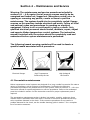
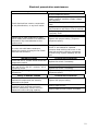
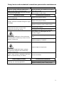
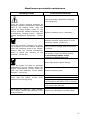
INSTRUCTION MANUAL
HF-2 Oil System
Manufacturer:
2150 Elmwood Avenue - Buffalo, New York 14207 USA
Telephone # 716-876-9951 Facsimile #716-874-8048 www.mokon.com
MOK2006 3/15
Table of Contents
Section 1 – Warnings and Cautions ....................................1
1.1 Electrical warning .................................................................................. 1
1.2 Hot fluid warning ................................................................................... 1
1.3 Cold weather caution ............................................................................. 1
1.4 Pump cavitation warning ........................................................................ 1
1.5 Overhead piping warning ........................................................................ 1
1.6 Short circuit current rating caution ........................................................... 2
1.7 No flow warning .................................................................................... 2
1.8 PPE ...................................................................................................... 2
1.9 Ergonomic Conformance Warning ............................................................ 2
Section 2 – Installation ......................................................3
2.1 Unpacking ............................................................................................ 3
2.2 Location ............................................................................................... 3
2.3 Warnings .............................................................................................. 4
2.4 Electrical connections ............................................................................. 4
2.5 Filling reservoir...................................................................................... 5
2.6 Fluid connections ................................................................................... 5
2.7 Ambient Operating Conditions ................................................................. 6
2.8 Dismantling/Decommissioning ................................................................. 6
Section 3 – Operation ........................................................7
3.1 Initial starting procedure ........................................................................ 7
3.2 Changing temperature setting ................................................................. 7
3.3 Shut down procedure ............................................................................. 8
3.4 Restarting procedure .............................................................................. 8
Section 4 – Maintenance and Service .................................9
4.1 Preventative maintenance ....................................................................... 9
Electrical preventative maintenance .......................................................... 10
ii
Pump/motor and mechanical connections preventative maintenance ............. 11
Miscellaneous preventative maintenance ................................................... 12
4.2 High temperature pump - zone pump ..................................................... 13
Exploded view drawing ............................................................................ 14
Seal replacement.................................................................................... 14
Supply pump assembly ........................................................................... 16
Maintenance and installation .................................................................... 17
Pump impeller clearance adjustment ......................................................... 17
Pump disassembly .................................................................................. 18
Pump impeller removal ........................................................................... 18
Pump seal replacement ........................................................................... 19
Pump seal replacement ........................................................................... 20
Pump inspection ..................................................................................... 20
Pump reassembly ................................................................................... 20
4.3 Heater element ................................................................................... 21
Wiring ................................................................................................... 21
Installation and maintenance ................................................................... 22
4.4 Low pressure safety switch ................................................................... 28
4.5 High temperature limit control ............................................................... 28
4.6 Recommended heat transfer fluids ......................................................... 28
4.7 Recommended system cleaning fluids .................................................... 30
Section 5 – Eurotherm controller ..................................... 32
5.1 Operation ........................................................................................... 32
Home list navigation ............................................................................... 32
Keys ..................................................................................................... 33
5.2 Automatic Tuning ................................................................................ 34
5.3 Troubleshooting ................................................................................... 35
5.4 Alarm indicators .................................................................................. 36
5.5 Automatic air purge operation (start-up) ................................................ 37
5.6 Restarting the automatic air purge timer (after start-up) .......................... 37
iii
5.7 Manual air purge operation (after start-up) ............................................. 38
5.8 Remote setpoint and retransmission “scaling” ......................................... 38
Section 6 – Options .......................................................... 39
6.1 Nitrogen blanket/sealed reservoir instructions ........................................ 39
6.2 Emergency stop................................................................................... 39
6.3 Process purge option (air connections) ................................................... 39
6.4 Automatic high-low heat ....................................................................... 40
6.5 In-line heat exchanger for additional cooling ........................................... 40
6.6 Cool down and automatic shut off .......................................................... 40
Section 7 – Troubleshooting guide ................................... 41
Section 8 – Condensed parts list ...................................... 44
Section 9 – Model Codes .................................................. 45
Section 10 – Warranty ..................................................... 46
iv
General machinery description and intended use
The Mokon temperature control system is a portable temperature control system circulating
fluid to control the temperature of a process. A typical machine consists of a pump,
heating/cooling elements, sensors and a microprocessor controller.
Example processes controlled by a Mokon system may include jacketed vessels, heat
exchangers and injection molding tools.
Refer to the flow schematic included with the instruction manual to better understand the
operation of the system.
v
Section 1 – Warnings and Cautions
Please read and understand this section before operating the
system!
1.1 Electrical warning
The Mokon temperature control system, as with all high voltage electrical equipment, should
be connected according to all local and national codes. All installation, maintenance, service,
repair, adjustment, and operation should be done only by qualified trained electrical
personnel who have read and completely understood this instruction manual. To the upper
right is a symbol for ELECTRICAL DANGER. When it is seen on the following pages of this
manual as well as on the system, care should be taken to avoid possible electric shock. All
maintenance and service should be performed with the power isolated and locked out
except where noted.
1.2 Hot fluid warning
Exercise EXTREME CAUTION while working on or in the area of the Mokon temperature
control system. The high temperature of the fluid will cause the process lines, the system
components, and the metal cabinetry to become VERY HOT and therefore should NOT be
touched. To the upper right is a symbol for SURFACE MAY BE HOT, HIGH
TEMPERATURE. When it is seen on the following pages of this manual, care should be
taken to avoid possible burns. All maintenance and service must be performed with the
system completely cooled. It is advisable to plug the process ports of any unused zones so
that if a wrong button is pressed, fluid will not be pumped through them.
1.3 Cold weather caution
If the Mokon temperature control system will be moved from your plant and will be
subjected to freezing temperatures, the water in the system must be completely drained
and/or sufficient antifreeze added to prevent serious water damage from freezing.
1.4 Pump cavitation warning
The process utilizing a Mokon temperature control system should be tested PRIOR to use. It
is essential that all water to be removed from the process prior to charging with oil. Water
concentration as low as 500 PPM in the oil will result in pump cavitations at about 220°F
(104°C) operating temperature.
1.5 Overhead piping warning
When overhead piping is connected to a Mokon temperature control system equipped with
an open reservoir or non pressurized expansion tank there is risk of overflow of the
system’s reservoir tank upon shutdown, this is due to the back flow of fluid volume from the
overhead piping system.
To prevent reservoir tank overflow an overhead piping kit should be installed. This kit is
available from Mokon as an option.
1
1.6 Short circuit current rating caution
Equipment supplied with a safety door disconnect or power cord is design rated for a short
circuit current rating (SCCR) of 10,000 amperes RMS if protected with a class "J" fuse.
1.7 No flow warning
It should be noted that if any external valves are installed in the process flow path, they
must be opened before starting the Mokon temperature control system or risk causing
serious damage to the system and the process.
Fluid must be established (flowing) through the Mokon temperature control system in order
for the safety features to work properly and adequately protect the Mokon temperature
control system.
The use of valves downstream of the Mokon temperature control system are not
recommended as they could potentially render the system safeties inoperative if closed.
This could cause serious system damage and would void the warranty. To avoid disabling
the standard safety features, please contact Mokon to discuss optional safety features that
may be required to adequately protect the assembly.
1.8 PPE
Personal Protective Equipment (PPE) should be worn when operating or performing
maintenance on machine. The minimal recommended PPE to be worn should be safety
glasses, gloves and hearing protection (where required
1.9 Ergonomic Conformance Warning
Depending on the configuration of your machine, the Human Machine Interface (HMI) may
be lower than ergonomic standards.
This system has been designed for use in non-potable water applications
only. For applications requiring potable water use please contact Mokon
directly to discuss a product offering.
2
Section 2 – Installation
2.1 Unpacking
Upon arrival inspection should be done to assure there was no damage during shipping. In
addition, all electrical and mechanical connections should be inspected to ensure that they
are secure and tight. This includes all electrical terminations, mechanical fitting union bulbs,
compression fittings, etc.
Note: Refer to section 4.1 Maintenance and service.
The maximum weights of the Mokon oil systems when drained of fluid are:
Series
# of
zones
1
HF
2
Heating kW
per zone
lbs
kg
12
24
36
48
60
72
96
108
120
132
144
12 (24)
24 (48)
36 (72)
48 (96)
60 (120)
72 (144)
590
660
730
830
920
1275
1475
1545
1640
1895
2250
1180
1320
1460
1660
1840
2550
268
300
332
377
418
580
670
702
745
861
1023
536
600
664
755
836
1159
Properly rated equipment should be used to move this machinery.
When removing system from pallet, lift from bottom only. Care should be taken to ensure
that the system will not tip. After removing from pallet, the system should only be placed on
a level surface.
2.2 Location
Mokon systems should be located in an area that provides adequate space for pedestrian
and vehicle traffic. If this is not feasible, owner should provide additional safeguards
including safety signs.
For optimum system performance, allow adequate space and ventilation around entire
system, as well as a means to direct vapors away from work area.
There should be a minimum of four (4) feet of clearance around the entire Mokon system
(all sides) for adequate ventilation and operation of the system.
If braking casters are included, they must be in the locked position when system is in the
operating position. Prior to moving, unlock the casters.
3
Customer supplied and installed air vents (mechanical or electrical) should be placed at the
highest point in the process for application where the process height is greater than eight
(8) feet above Mokon system.
2.3 Warnings
Owner should ensure by adequate supervision that correct safety, installation, maintenance
and operating procedures described in this manual, as well as recognized industry practice,
are followed by all personnel.
All panels must be in place during normal operation.
The top of the machinery should not be used for storage.
Power sources or energy types referred to in this manual are water, oil and electricity.
This machinery is not for use in hazardous or explosion proof environments.
Under normal operating conditions, the decibel level of the machinery is 85 db or lower.
When operating the machine, hearing protection is recommended.
Any alteration, additions or modifications to any part of the system must receive prior
written approval from Mokon’s Engineering or Customer Service Departments.
Refer to serial tag for motor and heater electrical information and schematic drawing
number.
Note: If your unit was purchased with a process purge option, review section 6.3 for
operating instructions.
2.4 Electrical connections
Warning: The Mokon temperature control system, as with all high
voltage electrical equipment, should be connected according to all
applicable state and local codes. All installation, maintenance,
service, repair, adjustment, and operation should be done only by
qualified trained electrical personnel who have read and completely
understood this instruction manual.
Before operating the Mokon temperature control system, the
grounding wire must be connected. The grounding wire is the green
or green and yellow wire connected to the frame of the system.
Connect ground wire to the ground screw (labeled GND or PE) located in the electrical box.
Connect power lines L1, L2, L3, to disconnect switch or terminal blocks marked L1, L2, and
L3 respectively, inside the electrical box. Overcurrent protection of the supply conductors
should be sized according to The National Electrical Code (NEC) and any other applicable
state and local codes.
4
2.5 Filling reservoir
Fill the reservoir with heat transfer fluid (see section 4.7 for recommended fluids) through
the fill port. The fill port is located on the side of the reservoir. Fill to the highest level on
the sight glass. See chart below for the total fluid capacity of your system.
# of zones
1
2
Heating capacity
kW per zone
Reservoir tank
volume (gallons)
12
24
36
48
60
72
96
108
120
132
144
12 (24)
24 (48)
36 (72)
48 (96)
60 (120)
72 (144)
18
38
38
38
38
38
58
58
78
78
78
38
78
78
78
78
78
Reservoir
tank volume
(liters)
70
144
144
144
144
144
220
220
296
296
296
144
296
296
296
296
296
Note: On initial start up, while purging the air from the system, it may be necessary to add
additional heat transfer fluid to the reservoir to compensate for the volume of fluid
consumed by this process.
Warning: On a standard system, a minimum operating fluid level of
½ full is recommended (optimum fluid level is ¾ full). It must be
maintained at all times. If the proper fluid level is not maintained,
serious damage may occur to the Mokon system. It is mandatory to
periodically inspect the fluid level sight glass and add heat transfer
fluid if required.
2.6 Fluid connections
Exercise extreme caution while working on or in the area of the
Mokon temperature control system. The high temperature of the
fluid will cause the process lines, the system components, and the
metal cabinetry to become very hot and therefore, they should not
be touched.
There are four (4) convenient and clearly marked connections, "To Process" (one for each
zone), "From Process" (one for each zone), "Supply Water" and "Drain Water." They are
located on the rear of the HF system.
5
Note: Quick disconnects should not be used on any of the connections, they will restrict the
flow.
Use full size unrestricted high temperature, insulated hose or pipe
for each connection.
To Process: Connect the port(s) to the process inlet(s), through which heat transfer fluid will
enter the process.
From Process: Connect the port(s) to the process outlet(s), from which heat transfer fluid
will leave the process.*
Supply Water: Connect the port to an adequate source of cold, clean supply water.
Drain Water: Connect the port to drain (or return line in an in plant closed recirculation
system).
Caution: If you are using brass, bronze or copper (yellow) metals in process plumbing that
will come in contact with the heat transfer oil, contact Mokon. Yellow metal promotes
oxidation of the oil, drastically shortening its life. DELF fluid greatly reduces the possibility of
fluid degradation due to metal deactivators in the fluid.
* A “Y” type strainer is provided to be installed in the “From Process” line. Make sure the
direction indicating arrow, on the body of the strainer, corresponds to the flow direction of
the fluid. It is recommended that the strainer be installed in the horizontal position, with the
“Y” pointed downward.
If the strainer must be mounted in the vertical position, below the process connection on
the Mokon system, a drip leg should be installed to trap debris that will dislodge from the
screen upon shutdown. Consult the factory if the strainer must be installed in this fashion.
2.7 Ambient Operating Conditions
Temperature: 5 – 40º C
Humidity: 0 – 95%
Altitude: 1000 meters above mean sea level
Storage/Transportation Conditions
Temperature: -25ºC – 55ºC
Humidity: 0 – 95%
(See section 1.3)
2.8 Dismantling/Decommissioning
Reference local codes for disposal
6
Section 3 – Operation
Prior to starting the Mokon system it may be necessary to tighten
the mechanical fittings on the piping. Vibration cause during
transport can loosen the fittings. Before proceeding, check and
tighten all of the mechanical fittings.
3.1 Initial starting procedure
•
Fill the Mokon temperature control system with heat transfer fluid. (See section 2.5
for filling reservoir)
•
Turn on the water supply connected to the Mokon temperature control system. (See
section 2.6 for fluid connections)
•
Turn on the electrical main disconnect switch. (See section 2.4 for electrical
connections)
NOTE: The covers of the system must be removed for the next two (2) procedures.
•
For each zone, check the pump alignment. (See section 4.2 for pump alignment)
•
For each zone, check the motor rotation by turning on the system momentarily
(press the “Start” button then the “Stop” button). As the pump slows down, check
the motor rotation. If the motor is not rotating in the direction of the arrow label
located on the motor housing (clockwise from the lead end), reverse any two power
cord leads (See section 2.4) to change the direction of the motor rotation.
•
Restart the system and set the controller to the minimum temperature. (See section
5 for specific controller operation instructions)
NOTE: The start button may have to be held in for up to 30 seconds in order to build
adequate pressure to start the system.
•
Allow the system to run for approximately 5 to 10 minutes at the minimum
temperature to purge the air from the system. The air is purged from the system
when the pressure gauge reading is steady (typically between 40 to 80 psi / 276 to
552 kPa depending on restrictions in your process) and when the pump runs smooth
and steady.
If the above procedure does not eliminate air in the system, turn the unit off then on
once or twice to break up the air pockets.
NOTE: The air purge button may be pressed to eliminate air in the system at any
time during operation.
•
Set the controller to the desired temperature. The system will reach the setpoint
temperature. (See section 5 for controller instructions)
3.2 Changing temperature setting
If a new temperature setting is required while the system is in operation, adjust the
controller to the new desired setpoint temperature. (See section 5 for controller
instructions)
7
3.3 Shut down procedure
Cool the Mokon temperature control system down by reducing the setpoint temperature to
150oF (66oC) or lower. When the system is cooled, push the "Stop" button to shut off the
system. DO NOT SHUT THE SYSTEM OFF AT ELEVATED TEMPERATURES; THIS CAN
BE DETRIMENTAL TO SYSTEM LIFE. The water and main electrical power to the Mokon
temperature control system may be turned off if desired but is not necessary unless the
system is being relocated or for prolonged shut down.
3.4 Restarting procedure
•
If the water lines and main electrical power have not been disconnected, refer to
section 3.1.
•
If the water lines and/or the main electrical power have been disconnected, refer to
section 2.4 for electrical connections, section 2.6 for fluid connections, and section
3.1 for initial start-up procedure.
8
Section 4 – Maintenance and Service
Warning: The maintenance and service procedures included in
sections 4.1 – 4.6 require that all energy sources need to be deenergized and locked out/tagged out (exceptions noted) prior to
opening or removing any panels, covers or doors to perform
maintenance. The system should also be completely cooled. Energy
sources on this machine include electrical and water. Follow all local
and national codes and procedures for working on electrical
equipment. Failure to do so could result in injury or death. Only
qualified electrical personnel should install, maintain, repair, adjust
and operate Mokon temperature control systems. The instruction
manual furnished with the system should be completely read and
understood before system maintenance is performed.
The following hazard warning symbols will be used to denote a
specific hazard associated with a procedure.
Electrical Danger
High Temperature
Surface May Be Hot
High Voltage &
Hot Surface
4.1 Preventative maintenance
Mokon temperature control systems are designed for a long, trouble free service life under a
variety of conditions, with a minimum of maintenance. Performing the following
preventative procedures will extend the life of your system. Refer to section 4.1 - 4.6 in the
instruction manual for specific adjustment or service procedures. Refer to the condensed
parts list included in section 8 of the instruction manual for proper replacement parts if
required.
The preventative maintenance section is broken into weekly, monthly, and every three
months checks. Associated with each check is a series of corrective procedures that may
solve a problem detected in the check. If the corrective procedures do not resolve a
problem detected in the check, see the trouble shooting guide in section 7 for a complete
list of corrective measures.
9
Electrical preventative maintenance
Weekly Checks
Corrective Procedures
Check electrical box interior components
for any discoloration, or any burn marks
Correct component wiring
Verify voltage and frequency stamped on
system matches customer supply voltage
and frequency
Correct excessive system load (current
draw)
Verify customer supply voltage is balanced
and fluctuations are within 15% of nominal
Verify wire gauge for main power hookup
is properly sized
Replace components if needed
Slightly tug on each conductor to make
sure it makes solid contact to its attached
component. Pay close attention to the
ground wires.
Tighten with proper tooling (Torque to
component specs)
For units with solid state contactors,
inspect the screen covering the fan inside
the electrical enclosure
If clogged with debris, clean or replace the
screen. If not cleaned or replaced
excessive heat build up can occur in the
electrical enclosure reducing component
life and wiring. System warranty will be
void.
Monthly Checks
Check that a N.C. contact exists across the
temperature switch
Check that the low pressure switch (PS)
has a set of N.O. and N.C. contacts, and it
is properly wired
Tighten all high voltage terminal
connections
Every 3 Months Checks
Check that the interior electrical and
mechanical components are securely
fastened to the panel
Check that the ratings of overload
protection (such as fuses and circuit
breakers) adequately protect the line's
maximum current carrying capacity
Corrective Procedures
Replace the switch if necessary
Correct wiring if necessary
Replace the switch if necessary
Tighten with proper tooling (Torque to
component specs)
Corrective Procedures
Tighten with proper tooling
Inspect/replace fuses
Inspect/replace motor starter overloads
10
Pump/motor and mechanical connections preventative maintenance
Weekly Checks
Check for foreign materials obstructing
airflow in the motor and pump area
Check the heat transfer fluid level through
the reservoir sight glass
Monthly Checks
Check that all bolts and screws are
securely tightened
Corrective Procedures
Remove all dust, lint, grease or oil with a
cloth and/or brush
Fill to at least ½ full, if low
Corrective Procedures
Tighten with proper tooling
Tighten with proper tooling
Visually check all threaded fittings for signs
of leakage
Replace necessary parts if leaks persist
Check that the motor current draw
matches the serial tag rating
Correct motor wiring
Verify supply voltage is balanced and
fluctuations are within 15% of nominal
Verify suction or discharged line not
partially clogged
Check gauge readings on the suction and
discharge side of the pump, and/or on the
cabinet (Power On)
Verify no restrictions in process or supply
lines
Replace gauge(s) if needed
Inspect/replace components
Check that all applicable lights, gauges,
and optional indicators are functioning
properly (Power On)
Check Y-type strainer, located on the from
and/or to process line(s) for debris
Semi Annual Checks
Check that all threaded fittings within the
fluid loop are securely tightened
Remove and clean
Corrective Procedures
Tighten with proper tooling
Replace necessary parts if leaks persist
11
Miscellaneous preventative maintenance
Monthly Checks
Corrective Procedures
Using a Voltmeter, determine if solenoid
coil is energizing
Check the cooling solenoid operation by
elevating setpoint temperature manually.
While in the heating mode, push the
manual air purge button. Listen for the
cooling solenoid's audible energizing and
de-energizing "clicking sound." Observe
process temperature decreasing. (Power
On)
Replace a solenoid valve, if necessary
Calibrate controller using section 5 in the
instruction manual (Power On)
Check the controller calibration by setting
the controller for three random setpoints
within the operating range of the system.
Observe that the process temperature
output is within the accuracy of the
controller. (Power On)
Verify the thermocouple wires at controller
are secure
If controller does not respond to any of the
above steps, consult the Mokon factory
Do not attempt repairs as the
warranty could become void.
Repair leaks and/or tighten fittings
Check the system for leaks at operating
temperatures. As the system reaches the
setpoint temperature, visually check for
leaks. Pay close attention to the heater
elements. (Power On)
Check that the heater current
matches the serial tag rating
draw
Check that the "Warning," "High Voltage"
and "Caution" labeling are adhering to the
correct locations
Replace necessary parts
Verify heater wiring stake-on is secured
Correct heater wiring
Verify customer supply voltage is balanced
and fluctuations are within 15% of nominal
Resistance reading is approximately 100
ohms across each element
Replace elements if necessary
Replace torn, damaged or missing labels
12
4.2 High temperature pump - zone pump
DANGER!
•
DO NOT perform service or maintenance when the pumping system is
pressurized or hot-serious injury of death from burn caused by hot oil
may occur.
•
DO NOT operate the pump in a manner that it was not intended to be
used.
•
DO NOT continue to operate the Mokon system when a known leak
exists or the system continues to smoke.
•
DO NOT continue to operate the pump when an unusual noise or
vibration occurs.
•
DO NOT operate beyond the pressure or temperature limits stated on
front cover of this manual.
•
DO NOT allow severe temperature changes to occur in a short period
within the Mokon system.
•
DO NOT mix different types or grades of oil with the Mokon system.
•
DO NOT use an oil that is not a recommended heat transfer oil by the
manufacturer.
•
DO NOT exceed the maximum oil temperature rated by the oil
manufacturer at the hottest point in the Mokon system.
FAILURE TO FOLLOW THE ABOVE LISTED PRECAUTIONARY
MEASURES MAY RESULT IN SERIOUS INJURY OR DEATH.
13
Exploded view drawing
REF #
1
2
3
4
5
6
7
8
9
QTY
1
1
1
1
1
1
1
1
1
DESCRIPTION
Impeller – Cast Iron
Seal Assembly
Hex Jam Nut – S.S.
Cooling Fan Clamp – Aluminum
Capscrew
Gasket
Clamp Capscrew
O-Ring – Viton
Adaptor – Docile Iron
REF #
10
11
12
13
14
15
16
17
QTY
1
1
1
1
1
1
1
1
DESCRIPTION
Isolator – Carbon Graphite
Drive Sleeve – Stainless Steel
Seal Housing – Ductile Iron
Lip Seal – Viton
Housing – Ductile Iron
Gasket
Pipe Plug S.S.
Capscrew
Seal replacement
•
Turn off the electric power and the water supply to the system and remove the
pump/motor assembly from the unit. (Follow the Lockout/Tagout procedure of your
company)
•
Remove the pump from the motor by loosening and removing the four mounting
screws holding the pump to the motor.
•
Remove the fan clamp (4) from the drive sleeve (11).
14
•
Remove the three capscrews (5) which attach the seal housing (12) to the adaptor
(9) and remove the seal housing (12).
•
Remove the ceramic seal seat from inside of the seal housing (12). Remove the
lipseal (13) from the other side of the seal housing (12).
•
Remove the seal assembly (2) from the drive sleeve (11).
•
Inspect all the parts of the seal assembly. If they show any signs of wear or
deterioration replace the entire seal assembly.
•
Make sure the drive sleeve (11) is clean and free of nicks or burrs. Use fine steel
wood to polish the sleeve.
•
Lubricate the drive sleeve (11) with any good grade of pump grease.
NOTE: Do not use oils or S.T.P. They allow the seal spring to set up too quickly on
the sleeve thus preventing free movement of the seal cage after assembly.
•
Lightly lubricate all internal surfaces of the seal spring with grease.
•
Slide the seal assembly (2) onto the drive sleeve (11).
•
Press the seal assembly (2) down far enough to compress spring and release. The
seal assembly (2) will return to free height.
•
Press the ceramic seal seat squarely onto the seal housing (12). Turn the seal
housing over and press the lipseal (30 onto the other side of the seal housing (12).
•
Attach the seal housing (12) to the adaptor (9) with the three capscrews (5). As
steady pressure is applied to the seal housing to hold it in place, thread in the three
capscrews (5) and torque them to 25 inch-lbs each. Working around the bolt circle,
tighten the capscrews (5) in 25 in-lbs increments until each screw is tightened 150
in-lbs.
•
Assemble fan clamp (4) to drive sleeve.
•
Assemble the pump to the motor. Slide the motor onto the pump. Install and tighten
the four mounting screws. Use shim gauges of 0.06 – 0.09 inches to shim the
impeller clearance from the housing. This can be done through the suction. Once the
shim is in place, tighten the drive clamp screws (7) to 50/70 inch-lbs. Remove the
shim and reinstall the motor onto the Mokon system.
15
Supply pump assembly
Exploded view drawing
Ref
No.
1
2
3
4
5
1
4
4
1
1
Mokon
Part No
034020
034004
034009
034040
034048
6
1
034008
7
4
034043
Qty
Description
Clamp Assembly
S.S. Lock-washer 3/8 x 1/8
S.S. Bolt 3/8 - 16 x 3/4 LG
S.S. 5/8 Bore Drive Sleeve
Adaptor Frame
Seal Assembly. 1" Viton Niresist
o-ring, seat
S.S. Stud 5/16"
Ref
No.
8
9
10
11
12
1
1
1
1
4
Mokon
Part No
034039
034046
034047
034042
034044
Gasket
Brass Impeller 3.25"
S. S. Lock Nut 3/8"
Housing
Brass Hex Nut 5/16"
13
4
034045
Brass Washer 5/8"
14
1
017044
Brass Pipe Plug 1/8"
Qty
Description
16
Maintenance and installation
The supply pump assembly consists of a housing, adaptor frame, stainless steel sleeve,
shaft seal, seal spring, impeller, drive clamp, gaskets, impeller lock nut, and stainless steel
fasteners. See the previous page for a drawing and a parts breakdown.
The impeller is threaded onto the shaft sleeve and locked in place by a lock nut. The shaft
sleeve is machined to precisely fit the shaft on the recommended motor. No provision is
made for an internal drive key and none is required. The drive clamp assembly replaces
internal drive keys, securely locks the shaft sleeve to the motor shaft, and serves
additionally as a liquid slinger to protect your motor.
The mechanical seal is the self-adjusting, greaseless type being lubricated by the liquid in
the pump. It requires no maintenance and provides long and trouble-free operation.
Because the seal is lubricated by liquid in the pump, the pump should never be operated
without liquid in the housing.
Mounting motor to supply pump assembly
•
Check the rotation of the motor to be sure it coincides with the required rotation of
the supply pump assembly.
•
Loosen the drive clamp assembly (1) but do not remove.
NOTE: If the motor shaft is a keyed shaft, remove the key before installing the
Mokon supply pump assembly. The drive clamp assembly on the Mokon supply pump
assembly is all that is required to drive the pump.
•
Slide the supply pump assembly onto the motor drive shaft (4), aligning the holes in
the adaptor frame (5) with tapped holes in the motor mounting face, until adaptor
frame (5) contacts the motor mounting face.
•
Install two S.S. bolts (3) (diagonally opposite) and tighten to secure the supply
pump assembly to the motor.
•
Center the drive clamp assembly (1) and tighten.
•
Proceed to page 18 to check the impeller clearance.
Pump impeller clearance adjustment
Remove the strip stock shim from the suction eye of the pump housing. This shim was
inserted to establish clearance between the face of the impeller and the housing. Rotate the
motor slowly, by hand, to make certain that the impeller does not rub the housing or the
adaptor frame. If the impeller does not rub install and tighten the remaining S.S. bolts to
secure the supply pump assembly to the motor.
If the impeller rubs, the impeller clearance can be adjusted by the following procedure:
•
Loosen the drive clamp assembly (1), but do not remove.
•
Move the impeller (9) either forward or backward using a screwdriver or move
impeller drive sleeve forward.
If the impeller still rubs after using the above procedure, it can then be adjusted as follows:
•
Remove the S.S. studs (7) and the housing (11).
17
•
Loosen the drive clamp assembly (1), but do not remove.
•
Remove the gaskets (8) from the housing (11).
•
Replace the housing (11), pushing against the impeller face. Secure the housing with
two S.S. studs (7), 180° apart.
•
Tighten the drive clamp assembly.
•
Remove the housing (11) and install one gasket (8).
•
Replace the housing (11) securing with two S.S. studs (7) 180° apart.
•
Rotate the motor shaft to check that the impeller does not rub. If it does, return to
step 6 and add another gasket. If not, install and tighten all remaining S.S. studs
(7).
If none of above procedure stops the impeller from rubbing, CONSULT THE FACTORY.
Pump installation
Use high temperature Teflon tape or high temperature RTV on all connections and be sure
all fittings are airtight, especially on the suction side of the pump. An air leak on the suction
side of the pump will prevent proper operation.
Pump disassembly
•
Close the gate valve on the reservoir tank.
•
Remove the S.S. studs (7) holding the housing (11) to the adaptor.
•
Remove S.S. bolts (3) which hold the adaptor frame (5) to the motor.
•
Loosen the drive clamp assembly (1) and remove the supply pump assembly.
The seal seat and seal cup will remain in the pump adaptor frame. If not damaged or worn,
do not remove. If necessary, remove the adaptor frame counter bore with a piece of wood
or a screwdriver handle inserted through the adaptor frame from the drive end. A sharp tap
or two is usually sufficient to knock out the seal seat. Use caution when removing the seal
seat so as not to damage the face or distort the metal seat.
Pump impeller removal
•
Remove the seal bellows and the spring assembly (6).
NOTE: The seal bellows will be bonded to the shaft sleeve and will require some
patience and caution to remove in order not to damage the seal bellows and cage.
•
Place the impeller drive sleeve (4) between two pieces of wood in a vise. Take care
so as not to damage sleeve.
•
Remove the impeller S.S. lock nut (10) from the end of the shaft sleeve. Unthread
the impeller (9) by turning counterclockwise (left hand).
18
Pump seal replacement
•
Make sure impeller shaft is CLEAN and free of nicks or burns. Use fine steel wool to
polish sleeve.
•
Lubricate the shaft with any good grade of water pump grease.
•
Lightly lubricate all internal surfaces of the seal spring with grease.
•
Place the spring over the impeller shaft (large diameter end) against the impeller
hub. Place the seal cage over the sleeve with carbon washer facing away from the
impeller.
NOTE: Do not use oils or S.T.P. They allow the seal bellows to set up too quickly
on the sleeve thus preventing free movement of the seal cage after assembly.
•
Press the seal assembly down far enough to compress spring and release. The seal
assembly will return to free height.
•
Lubricate the seal seat cavity in the pump frame with grease.
•
Lubricate the seal seat gasket with grease.
•
Use a wood dowel of sufficient diameter to press the seal seat squarely into cavity on
pump frame. HAND PRESSURE ONLY.
NOTE: Polished metal surface must face opposite the seal seat cavity on pump
frame. Optional ceramic seal assemblies require less pressure to seat squarely, too
much pressure will crack ceramic seal.
•
Place the impeller and the seal assembly in the pump housing. Affix the gasket on
the frame over the drive sleeve onto the housing.
19
Pump seal replacement
•
Attach the pump frame to pump head with bolts and secure evenly. Install the shaft
retaining collar onto the shaft and attach entire assembly to motor. Tighten the
retaining collar with Allen wrench.
•
See page 18 to adjust impeller clearance
Pump inspection
Check all parts for wear. For ease of reassembly, the shaft sleeve should have all nicks and
burns removed. Replace damage parts with new parts. Inspect the seal seat and seal cup
for grooves, scuff marks, or other deterioration. If a perfect lapped surface remains on the
seal seat, it may be reused. If the seal cup is in good condition it may be reused. If the seal
seat, cup, washer, or bellows are damaged or worn, a new seal assembly should be
installed. (See page 20 for seal replacement)
Pump reassembly
Clean all castings with mild solvent such as kerosene. All dirt and foreign matter should be
removed.
Reassemble the supply pump assembly. See page 17 for instructions on mounting the
motor to the supply pump assembly.
20
4.3 Heater element
Wiring
21
Installation and maintenance
22
23
24
25
26
27
4.4 Low pressure safety switch
Mokon HF series systems are equipped with two low pressure safety shut down switch.
The low pressure switches are located on the discharge side of the zone pump and on the
process return line. This switch incorporates an interlock to prevent the operation of the
system should the heat transfer fluid be insufficient. The switch is factory set at 5 PSI (34
kPa) and should not be adjusted without WRITTEN CONSENT FROM THE MOKON
FACTORY.
4.5 High temperature limit control
Mokon HF series systems are equipped with one or more high temperature limit controllers.
Each controller is factory set to shut the Mokon system off at 610°F (321°C). This controller
should not be adjusted without WRITTEN CONSENT FROM THE MOKON FACTORY.
NOTE: Refer to section 1.7 for the No flow warning.
4.6 Recommended heat transfer fluids
Heat transfer systems manufactured by Mokon are thoroughly tested prior to shipment for
leaks, component operation, and accuracy (calibration).
All Mokon heat transfer systems are tested using Mokon’s DELF600 heat transfer fluid.
NOTE: The use of any heat transfer fluid other than the ones listed below may void
your warranty. Consult the Mokon service department with questions on fluid
selection.
When operating the Mokon system, routine fluid samples should be taken and analyzed
regularly. These samples can help determine your unique change point. A fluid sample
should be taken from a flowing line and cooled below 100°F (38°C) before placing in a clean
sample container and sent to the heat transfer manufacturer for analysis. The information
gathered from the sample can then be useful in developing a heat transfer fluid
maintenance program.
Mokon recommends the following heat transfer fluids for use in Mokon systems. A short
description of each fluid offered including the recommended applications for the fluids.
Mokon’s heat transfer fluids:
Mokon’s heat transfer fluids last longer and help keep your system cleaner...which means
longer life for parts like pumps and rotary seals!
Mokon’s heat transfer fluids are:
Extremely stable
Highly refined using naturally resilient base stocks like, severely hydro treated paraffinic
oils
Enhanced with a proprietary blend of additives.
DELF450 - engineered for applications between 30°F and 450°F (-1 to 232oC) offering an
excellent alternative to costly synthetics and aromatic fluids. The fluid delivers superior
28
resistance to sludging, a problem plaguing most other fluids, and defends against extreme
oxidation.
DELF600 - rated to 600°F (315oC), it contains the industry’s most aggressive blend of
additives specifically engineered to withstand the extreme oxidation environments in open
systems and give unsurpassed levels of protection and service life. All Mokon HTF systems
are tested using this fluid!
DELF450FG and DELF600FG - are engineered to comply with the demands of food grade
applications and meet USDA requirements for incidental food contact (H1) and
21CFR1783570, and are NSF registered.
DELF 450 & 600 and DELF 450FG & 600FG may be used safely in the Mokon HTF 350,
500, 600, and HF Series systems.registered.
Other heat transfer fluids suitable for use with Mokon’s systems:
Multitherm
PG-1 is a food grade heat transfer fluid for use up to 600°F (316°C). PG-1 meets
specifications of 21CFR72.878, which covers the use of white mineral oils in food
applications according to the limits and conditions of the regulations. PG-1 is Kosher
certified and rated HT-1 for incidental contact by NSF.
IG-4 for use in systems up to 600°F.
Paratherm
NF is formulated for service up to 600°F (316°C). NF fluid provides excellent heat transfer
and is low in viscosity.
HE is a high flash and fire point heat transfer fluid is rated for an optimal service range of
150°F - 600°F (66°C - 316°C).
Petro-Canada Products
Calflo FG for use in closed loop, non-pressurized, indirectly heated, liquid phase heat
transfer systems with operating temperatures up to 620°F (326°C). It is accepted by the
Canadian Department of Agriculture and approved USDA H1 for incidental food contact.
Calflo HTF is recommended for use in heat transfer systems with operating temperatures
up to 620°F (326°C) and film temperatures up to 650°F (343°C). Calflo HTF is a unique heat
transfer fluid that combines the thermal efficiency and cleanliness of paraffinic hydrocarbon
with the high temperature stability of a chemical synthetic.
Solutia Inc.
Therminol 66 heat transfer fluid is designed for use in non-pressurized/low pressure,
indirect heating systems with maximum bulk temperatures up to 650°F (343°C) and film
temperatures up to 705°F (374°C).
Duratherm
29
Duratherm 450 – Heat transfer fluid rated to 450°F.
Duratherm 600 – Heat transfer fluid rated to 600°F, used in a variety of applications.
Duratherm Lite - Heat transfer fluid with the same physical properties as Duratherm 600
but formulated with a lighter dose of additives. Duratherm Lite is economically ideal for
applications that are prone to fluid loss or attrition due to equipment change.
Duratherm FG is rated for use up to 620°F and is engineered and manufactured to comply
with the demands of food grade applications. Duratherm FG meets USDA requirements for
incidental food contact (H1) and meets the requirements of 21CFR1783570 and is NSF
registered.
4.7 Recommended system cleaning fluids
NOTE: The use of any system cleaning fluid other than the ones shown below may
void your warranty. Consult the Mokon service department with questions on fluid
selection.
The use of these fluids is done at the owners own risk. Mokon assumes no responsibility for
the effectiveness or the liability for damages that may occur while using these fluids. Please
consult the manufacturer’s instructions for safe and proper use prior to using any of the
cleaning fluids listed in this manual.
*When operating the Mokon HTF system, routine fluid samples should be analyzed. Fluid
samples for analysis should be taken regularly. These samples can help determine your
unique change point. A fluid sample should be taken from a flowing line and cooled below
100°F (38°C) before placing in a clean sample container and sent to the heat transfer
manufacturer for analysis. The information gathered from the sample can then be useful in
developing a heat transfer fluid maintenance program.
Mokon’s heat transfer system cleaner:
The industry's first heat transfer system cleaner that provides full production while cleaning!
Mokon’s DELFClean - a long life, preventative maintenance and light duty system cleaner
that is capable of functioning as a long-term heat transfer fluid up to 550°F (288oC). This
fluid is odorless and easily handles long term operation while seamlessly allowing production
to continue uninterrupted for a complete oil cycle.
Other cleaners suitable for use with Mokon’s systems:
Multitherm
Multitherm PSC cleaning fluid is designed for use in general maintenance of larger heat
transfer fluid systems. PSC is formulated to be compatible with all MultiTherm heat transfer
fluids as well as most others so that small residual amounts left in the system will not cause
a problem.
30
Paratherm
Paratherm SC® system cleaning liquid is formulated to dissolve and suspend sludge and
carbon lumps frequently produced in hot oil temperature control units where petroleum or
glycol-based heat transfer fluids have been used.
Duratherm
Duratherm Duraclean is a preventative maintenance and light duty system fluid up to
550°F.
Duratherm’s Duraclean Ultra is a high performance, fast acting and High flash point
terpene solvent. A unique combination of terpene, alcohols, penetrants, and surfactants
designed to remove grease, oil, and carbon deposits. This fluid can be run to 150°F max.
Duraclean Ultra is environmentally safe, low toxicity, biodegradable, and comes from a
renewable natural resource.
31
Section 5 – Eurotherm controller
Refer to the 4th character in the model code on the serial tag and
then the model code in section 10 to determine your controller type.
5.1 Operation
This section of the manual contains all essential information needed to operate the
controller. Contact Mokon Customer Service with controller problems as well as warranty
and repair issues.
The controller is configured by model number. Inputs, outputs and alarm types are preset.
Final setup and configuration are done from the keypad. The controller has four basic
modes: Operator 1, Operator 2, Operator 3 and the configuration level.
The controller’s is default level is Operator 1, and is used for day to day operation.
Note: Operator 2, 3 and configuration are password protected.
Home list navigation
To step through list levels press and hold the Page button until level 1 is obtained. Press the
up button or the down button to change levels.
To step through parameters within a particular list, press the Scroll button until the required
parameter is obtained.
To change the value (or state) of a parameter, press the Up button or the Down button.
*Refer to section 5.1 Keys for button locations and descriptions.
Levels
Operator 1
Parameter Mnemonic
SP1
SP2
DWELL
Scroll
WORKING OUPUT The
active output value
SETPOINT 1
SETPOINT 2
SET TIME DURATION
T-REMIN
TIME REMAINING
*
*
*
A1.xxx
A2.xxx
A3.xxx
ALARM 1 SETPOINT
ALARM 2 SETPOINT
ALARM 3 SETPOINT
*
A4.xxx
ALARM 4 SETPOINT
A.TUNE
ID
Auto Tune Enable
Customer ID
WRK.OP
Function
Output %
------------Auto air purge time setting
Time remaining for Auto
Air Purge
Only shown if the alarm is
configured.
Where: xxx = alarm type.
HI = High alarm;
LO = Low alarm
d.HI – Deviation high:
d.LO = Deviation Low:
D.HI = Deviation high
Controller Revision #
*Optional
32
Keys
NOTE: Pictured is the 3216 Eurotherm controller - this also applies to 3116, 3204 and 3208
series controllers.
*Optional
33
Button or
Indicator
Name
OP1
Output 1
OP2
Output 2
When lit, it indicates that heating output is on.
“HEATING” will scroll.
When lit, it indicates that cooling output is on.
“COOLING” will scroll.
Page button
Press to select a new list of parameters.
Scroll button
Press to select a new parameter in a list.
Down button
Press to decrease a value in the setpoint.
Up button
Press to increase a value in the setpoint.
*ALM
Alarm
OP4
Output 4
RUN
Explanation
Flashes when in alarm condition. “ALARM
MESSAGE” will scroll.
When lit indicates that the air purge output is
on. “AUTO AIR PURGE” will scroll.
When lit indicates that the air purge output is
Timer Running on. “AUTO AIR PURGE” will scroll.
5.2 Automatic Tuning
In tuning, you match the characteristics (PID parameters) of the controller to those of the
process being controlled in order to obtain good control. Good control means:
•
Stable, ‘straight-line’ control of the PV as setpoint without fluctuation.
•
No overshoot or undershoot, of the PV setpoint.
•
Quick response to deviations from the setpoint caused by external disturbances,
thereby rapidly restoring the PV to the setpoint value.
•
Tuning involves calculating and setting the value of the parameters listed in the table
below.
The PID controller consists of the following parameters:
Parameter
Proportional
Band
Integral Time
Derivative Time
High Cutback
Meaning or Function
The proportional term, in display unit or %, delivers and output which
is proportional to the size of the error signal.
Removes steady state control offsets by ramping the output up or
down in proportion to the amplitude and duration of the error.
Determines how strongly the controller will react to the rate of change
in the measured value. It is used to prevent overshoot and
undershoot and to restore the PV rapidly if there is a sudden change
in demand.
The numbers of display units, above setpoint, at which the controller
will increase the output power, in order to prevent undershoot on cool
down.
34
Low Cutback
Relative Cool
Gain
The number display units, below setpoint, at which the controller will
cut back the output power, in order to prevent overshoot on heat up.
Only present if cooling has been configured. Sets the cooling
proportional band, which equals the heat proportional band value
divided by the cool gain value.
The controller uses a one shot tuner which automatically sets up the initial values of the
parameters listed in the table.
The ‘one-shot’ tuner works by switching the output on and off to induce an oscillation in the
measure value. From the amplitude and period of the oscillation, it calculates the tuning
parameter values.
If the process cannot tolerate full heating or cooling being applied, then the levels can be
restricted by setting the high power limit (‘O P .HI’) and low power limit (‘O P .LO’).
However, the measured value must oscillate to some degree for the tuner to be able to
calculate values.
A One-Shot tune can be performed at any time, but normally it is performed only once
during the initial commissioning of the process. However, if the process under control
subsequently becomes unstable (because its characteristics have changed), you can re-turn
again for the new conditions.
It is best to start tuning with the process at ambient conditions and with the SP close to the
normal operating level. This allows the tuner to calculate more accurately the low cutback
and high cutback values that restrict the amount of overshoot or undershoot.
How to Tune:
•
Set the setpoint to the value at which you will normally operate the process.
•
Operator level 1 list, press,
•
Press the Page and Scroll buttons together to return to the Home display. The
display will flash [tunE] to indicate that tuning is in progress.
•
After one (1) minute to determine steady state conditions the controller will induce
an oscillation in the temperature by turning the output on and then off. The first
cycle will not complete until the measured value has reached the required setpoint.
until A.Tune appears. Set to ON.
5.3 Troubleshooting
Diagnostic alarms:
Display Shows
E.ConF
What it means
A change made to a
parameter takes a finite
time to be entered. If the
power to the controller is
turned off before the
change has been entered
then this alarm will occur.
Do not turn the power off
What to do about it
Enter configuration level
then return to the required
operating level. It may be
necessary to re-enter the
parameter change since it
will not have been entered
in the previous
configuration.
35
to the controller while ConF
is flashing.
E.CAL
Calibration error
E2.Er
EEPROM error
EEEr
Non-vol memory error
Re-instate Factory
calibration
Return to factory for repair
Note the error and contact
your supplier
Invalid input type. This
refers to custom
Go to the INPUT list in
linearization which may not
configuration level and set a
E.Lin
have been applied corrector
valid thermocouple or input
or may have been
type.
corrupted.
Note: Some error messages may not appear, depending on the controller options.
5.4 Alarm indicators
•
ALM beacon flashing red = a new alarm (unacknowledged).
•
This is accompanied by a scrolling alarm message. A typical default message will
show the source of the alarm followed by the type of alarm. For example, “ALARM 1
FULL SCALE HIGH’.
•
If more than one alarm is present further messages are flashed in turn in the main
display. The alarm indication will continue while the alarm condition is present and is
not acknowledged.
•
ALM beacon on continuously = alarm has been acknowledged.
To acknowledge an alarm
Press
and
together.
Non-Latched Alarms
Alarm condition present when the alarm is acknowledged.
•
ALM beacon on continuously.
•
The alarm message(s) will continue to scroll.
This state will continue for as long s the alarm condition remains. When the alarm condition
disappears all indication also disappears.
If the alarm condition disappears before it is acknowledged the alarm reset immediately.
36
5.5 Automatic air purge operation (start-up)
All systems with this controller are equipped with our auto-air purge function, it is factory
set for five (5) minutes. When the system is started, the controller will operate a timer for
five (5) minutes. The controller should be set at the minimum temperature, and the
scrolling text will read “Auto Air Purge.” OP4 and Run will illuminate on the controller. The
system should automatically be purged of air at the end of the five (5) minute timer. If
pressure gauges are still erratic or air appears to still be present, refer to section 5.6 for
restarting the automatic air purge timer.
Adjusting Auto Air Purge Timer (factory default set for 5 minutes)
•
Press scroll button, toggling until you see the parameter DWELL.
•
Using the arrow keys, change to desired setting
•
The DWELL parameter relates to time in minutes. (The amount of time it will take to
purge your process loop will be affected by the size of the loop and the backpressure
on your drain.)
•
Wait for the display to flash.
•
Press Page button.
•
Unit will return back to the normal user screen.
Symbols:
Page button
Scroll button
Down button
Up button
5.6 Restarting the automatic air purge timer (after startup)
After the original start-up of the system (Section 5.5), you can Run, Hold, or End the
automatic air purge timer.
Operation
Action
Indication
Press and quickly release
Beacon – RUN = On
To Run the timer
OP4 = On
+
Scrolling test display: “AUTO AIR PURGE”
Press and quickly release
Beacon – RUN = Flashing
To Hold the timer
OP4 = On
+
Scrolling test display: “TIMER HOLD”
Beacon
– RUN = Off
Press and hold
+
To End the timer
OP4 = Off
for more than 1 second
Timer has timed out
Beacon – RUN = Off
(END state)
OP4 = Off
37
5.7 Manual air purge operation (after start-up)
There is a manual purge button that can be used after the Automatic Air Purge time has
expired. This is a momentary push button.
5.8 Remote setpoint and retransmission “scaling”
Scaling of the 4-20mA and 0-10V signals for this option are as follows:
•
•
4mA or 0V = minimum system operating temperature.
20mA or 5V, 10V = maximum system operating temperature.
NOTE: Maximum system operating temperature value is reflective of the series system
purchased, (refer to serial tag for maximum operating temperature located on Mokon
system).
Consult customer service at Mokon factory (716) 876-9951,
regarding system’s minimum and maximum temperatures if there
are any questions.
38
Section 6 – Options
6.1 Nitrogen blanket/sealed reservoir instructions
•
For systems with this option, the system is provided with a sealed reservoir top in
order to accommodate a blanket of nitrogen inside the oil reservoir.
•
The purpose of the blanket is to prevent oxidation of the heat transfer fluid.
•
Once the reservoir is filled and the process is fully purged of air, the ½” connections
(if supplied) on the rear of the unit should be utilized to maintain a blanket of
nitrogen inside the tank. Do not install a fitting in the Overflow/Fill port until the
process is fully purged of air.
•
Pressure 0.1 inches of water column is all that is required to maintain an adequate
blanket.
Use extreme caution when purging the reservoir. The reservoir is not designed
as a pressure vessel. The nitrogen blanket shall not exceed 1 psi.
6.2 Emergency stop
The emergency stop device will shut the machine down regardless of the operating
mode. Once the emergency stop device has been activated, it must be disengaged by
turning the button clockwise. Disengaging the emergency stop will not restart the
machinery but only permit restarting.
•
•
Per the risk assessment of the machine, the emergency stop is not wired to a safety
rated relay.
Do not wire additional safety components to the Mokon stop relay or modification of
the emergency stop circuit is prohibited.
6.3 Process purge option (air connections)
To facilitate mold changes with a minimum amount of oil loss from the hoses and the
process, a process purge system via air is provided as an option.
NOTE: If additional fluid has been added to the Mokon system after initial start up, it will be
necessary to drain the excess fluid prior to using the process purge as to avoid overflowing
the reservoir tank.
The following is the procedure to utilize this process purge option:
•
Turn the controller to the minimum setting and wait until the process temperature is
below 130°F. (See section 5 for controller instructions)
•
Shut off the zone by pressing the “Stop” button.
•
Connect the Air Supply to the Air Inlet on the system.
Warning: Air supply pressure should not exceed 15 PSIG (103 kpa).
39
•
Depress the “Process Purge” button on the control panel.
The fluid in the process loop will be returned to the reservoir.
•
Repeat steps 1 – 4 for each system.
•
Refer to section 3.1 to restart the system.
NOTE: The time required to purge the system is based on the hold up volume of the
process and the air supply to the system.
6.4 Automatic high-low heat
•
For systems supplied with this feature, the low-heat setting is achieved whenever the
temperature controller calls for heat. The high-heat setting is activated by a relay
output from the controller based on an “event”.
•
On start-up from a temperature lower than set point, the unit will be in high-heat.
When the “to process” fluid temperature reaches 10°F below set point, the controller
will switch to low-heat. It will stay in low-heat until the fluid temperature drops to
10°F below set point.
6.5 In-line heat exchanger for additional cooling
•
To achieve a lower “to process” fluid temperature. Mokon provides an option of
installing a shell-and-tube heat exchanger directly in the “to process” line. This is to
supplement the indirect cooling already provided by the cool-oil reservoir.
•
The heat transfer fluid is allowed to flow through the exchanger constantly. A
solenoid valve, cycled by the temperature controller, based on an “event”, controls
the flow of cooling water.
•
To prevent thermal shock, the cooling water is not allowed to flow through the heat
exchanger until the oil temperature reaches 150°F from a higher set point.
•
The controller is programmed so that the “event” is not triggered on the ramp to set
point. When the controller set point is lowered to 150°F or lower, the cool-oil
reservoir will be adequate to cool the fluid to 150°F. Once the 150°F temperature is
achieved, the controller will open the cooling water solenoid and control the process
accordingly.
6.6 Cool down and automatic shut off
This option consists of an activation button labeled Auto Cool / Shutdown, a relay, and a
timed relay.
To enable this feature:
While the unit is currently in operation, push the black button labeled Auto Cool / Shutdown.
The machine will disable heating and start cooling for the preset amount of time.
When the time runs out the machine will shut down.
If needed the machine can still be shut down by pressing the stop button.
A Timed Relay (TDR) mounted inside the machine’s electrical enclosure controls the amount
of time the machine cools before shutting down. Rotating the dial on the front of the TDR
can change the amount of time. The factory-preset time limit is 3 minutes; the adjustable
range of the TDR is from zero to ten minutes.
40
Section 7 – Troubleshooting guide
Problem
Possible Cause
System unplugged / power
off
Improper power source
wiring
Blown fuse at power supply
System will not start
Blown control circuit fuse
Low voltage
Running pilot does not go on
High temperature limit
control
Process purge switch (if
supplied) in neutral position
System unplugged / power
off
Blown fuse at power supply
Blown control circuit fuse
System runs momentarily
Pressure will no build up
Pressure surges erratically
and system will not hold
temperature
Bulb burn out
High temperature limit
control
Motor starter thermal
overloads tripped due to
motor overload
Corrective Measure
Plug system in / turn power
on
Check wiring (electrical
schematics) and correct
Isolate open fuse and replace
Replace and check for
ground condition
Measure incoming voltage, if
too low correct
Consult factory
Switch to “Forward” or
“Reverse”
Plug system in / turn power
on
Isolate open fuse and replace
Replace and check for
ground condition
Replace bulb
Consult factory
Consult factory
Incorrect pump location
See section 3.1 to check and
correct motor rotation
Entrapped air
See section 3.1
Pump relief valve stuck open
Consult factory
Inadequate fluid level
Check that sight glass reads
at least ½ full, if not add
fluid
Pump needs adjusting
See section 4.2
No fluid in the pump
Prime the pump
Reservoir tank valve closed
Open valve
Entrapped air
See Section 3.1
Check that sight glass reads
at least ½ full, if not add
fluid
Repair leak
Drain and replace fluid
Inadequate fluid level
Suction line leak
Contaminated fluid
41
Problem
Extreme pressure build up
High pressure and erratic
temperature
Loss of pressure and
volume output
Temperature climbs beyond
setpoint
System does not reach
and/or hold temperature or
slow response after
changing temperature
setting
Variance in temperature
readings
Possible Cause
Plugged flow paths,
inadequate circulation
through process and
connecting lines
Plugged flow paths,
inadequate circulation
through process and
connecting lines
Inspect; if plugged,
dislodge
Clean strainers
Inspect; if plugged,
dislodge
Clean strainers
Entrapped air
See section 3.1
Zone pump needs adjusting
Pressure gauges
See section 4.2
Inspect/replace component
Check that sight glass reads
at least ½ full, if not add
fluid
Inspect/replace component
Inadequate fluid level
Cooling valve
Pump relief valve stuck
open
Heater contactor
Temperature controller
Thermocouple or RTD
Controller calibration
Contaminated fluid
Heater burn out
Temperature controller
Kilowatt capacity
inadequate
Loose electrical connections
Thermocouple or RTD
Controller calibration
Cooling valve stuck open
Plugged flow paths,
inadequate circulation
through process and
connecting lines
Contaminated fluid
Kilowatt capacity
inadequate
Inadequate fluid level
Reservoir tank overheating
Corrective Measure
Water not flowing through
heat exchanger
Cooling valve stuck open
Relief valve stuck open
Consult factory
Inspect/replace component
Inspect/replace component
Inspect/replace component
See controller section 5
Drain/replace fluid
Inspect/replace component
Inspect/replace component
Consult Mokon engineering
Tighten connection or
replace broken wires
Inspect/replace component
See section 5
Consult factory
Inspect; if plugged,
dislodge
Clean strainers
Drain and replace fluid
Consult Mokon engineering
Check that sight glass reads
at least ½ full, if not add
fluid
Consult factory
Consult factory
Inspect/replace component
42
Problem
Noisy pump
Possible Cause
Corrective Measure
Entrapped air
Pump needs adjusting
Pump needs alignment
Worn coupling and/or
grommet between pump
and motor
See section 3.1
See section 4.2
See section 4.2
Worn bearing on pump
Inspect/replace component
Leak on suction side of
pump
Repair leak
Inspect/replace component
43
Section 8 – Condensed parts list
Part No
Description
006256
006257
24 amp motor contactor 110V coil
40 amp heater contactor 110V coil
006366
006367
1.0 – 5.0 amp overload (refer to motor name plate information for
3.2 – 16 amp overload proper overload)
008056
0 – 160 PSI pressure gauge
011070
12 kW heater
022038
022142
Start/stop button
Low pressure safety switch
025107
Cooling solenoid valve
Zone pump/motor replacement parts – consult the Mokon factory
Supply pump assembly parts:
034008
034039
034040
Seal assembly
Gasket
Drive sleeve
040011
Thermocouple
For additional part numbers refer to the specific section in the
instruction manual or consult the Mokon factory (716) 876-9951.
44
Section 9 – Model Codes
HF Oil Model Codes
Model #
HF441200
Pump Style
See Option Code
HF HF Series Oil Systems (1998)
Kilowatt Capacity
Voltage
12
12 kW
2 230 Volts / 3 Phase / 60 Hertz
24
24 kW
3 380 Volts / 3 Phase / 50 Hertz
36
36 kW
4 460 Volts / 3 Phase / 60 Hertz
48
48 kW
5 575 Volts / 3 Phase / 60 Hertz
60
60 kW
6 415 Volts / 3 Phase / 50 Hertz
72
72 kW
7 208 Volts / 3 Phase / 60 Hertz
9 Special Voltage, see option code
84
84 kW
96
96 kW
108 108 kW
Controller & GPM
120 120 kW
2 Eurotherm One zone, 90 GPM
132 132 kW
3 Eurotherm Two zone, 90 GPM
144 144 kW
4 *Eurotherm One zone, 40 GPM
5 *Eurotherm Two zones, 40 GPM
*Prior to 6/4/01, was Barber-Colman
6 *Eurotherm One zone, 60 GPM
7 *Eurotherm Two zones, 60 GPM
8 Eurotherm One zone, 120 GPM
9 Eurotherm Two zone, 120 GPM
A Special One zone, 40 GPM
B Special Two zones, 40 GPM
C Special One zone, 60 GPM
D Special Two zones, 60 GPM
E Special One zone, 90 GPM
F Special Two zones, 90 GPM
G Special One zone, 120 GPM
H Special Two zone, 120 GPM
I
Eurotherm Three zones, 40 GPM
J Special Three zones, 40 GPM
Effective 8/21/06-UL labeled Electrical subpanel
45
Section 10 – Warranty
OIL SYSTEMS WARRANTY
All new temperature control systems manufactured by MOKON are guaranteed to be free
from defective material or workmanship for a period of one (1) year from the date of
purchase. All Standard Microprocessor controllers are covered by a five (5) year warranty,
Microprocessors with special features are covered by a three (3) year warranty and Solid
State controllers are covered by a one (1) year warranty. MOKON'S obligation under the
WARRANTY SHALL BE LIMITED, TO THE ORIGINAL CUSTOMER, TO REPAIR OR REPLACE
DEFECTIVE PART(S) OF THE TEMPERATURE CONTROL SYSTEM, UPON CUSTOMERS
COMPLIANCE WITH THE INSTRUCTIONS CONTAINED HEREIN. Upon discovery of any
alleged defect, it is the responsibility of the customer to contact the MOKON Service
Department with the complete model number, serial number and the date of purchase.
MOKON’S obligation under this warranty is limited to make good, from or at its factory, any
parts that are returned to the company (prepaid) and deemed to defective, within the time
frame of the warranty. The customer also has the option of forwarding the system to
MOKON (Buffalo, NY), prepaid by the customer and with a return authorization from MOKON
for inspection and component replacement or repair. Repair or replacement in any manner
provided above shall constitute a fulfillment of all liabilities of MOKON concerning the quality
of the temperature control system.
No allowances, credits or reimbursements will be made for any replacement or repair made
or provided for by the customer unless authorized in advance, in writing, by MOKON.
NOTE: The use of any heat transfer fluid other than the ones recommended in the
instruction manual or approved by Mokon in writing, may void your warranty.
Consult the Mokon service department with questions on fluid selection.
The warranty set forth above is in lieu of any and all other warranties expressed
or implied including warranties of merchantability and fitness for a particular
purpose. Mokon shall in no event be liable for any consequential damages or for
any breach of warranty in an amount exceeding the original price of the unit.
Mokon’s products are not guaranteed against damage caused by
corrosion.
2150 Elmwood Avenue - Buffalo, NY 14207
P# 716-876-9951 - F#716-874-8048 - www.mokon.com
46
47