1
RT heating system
IRC control system for direct electric heating
version 1.3
BMR trading
Horní lán 17
779 00 Olomouc
Czech Republic
1
Tel: +420 778 066 566
[email protected]
www.bmr-trading.com
Development and production of systems for measurement and control
Content
1. General introduction and description........................................................................................................................... 3
2. Description................................................................................................................................................................... 3
2.1.Description of parts................................................................................................................................................. 5
2.2.Main elements......................................................................................................................................................... 5
2.2.1.Control unit HC64................................................................................................................................................................. 5
2.2.2.Power switching unit............................................................................................................................................................. 5
2.2.3.Analogue temperature sensors............................................................................................................................................ 9
2.2.4.Digital temperature sensors............................................................................................................................................... 10
2.3.Optional accessories............................................................................................................................................. 11
2.3.1.RTR concealed frame......................................................................................................................................................... 11
2.3.2.RT_5kW.............................................................................................................................................................................. 11
2.3.3.LOW modem...................................................................................................................................................................... 11
2.3.4.WTR01 roof windows warming........................................................................................................................................... 11
2.3.5.Window contact.................................................................................................................................................................. 11
2.4.Design and installation of regulation system......................................................................................................... 11
2.4.1.Lowering the MCB value.................................................................................................................................................... 12
2.4.2.Underfloor heating control.................................................................................................................................................. 12
2.4.3.Recommendation for sensor installation according to type of room..................................................................................13
2.4.4.Important instruction for installation.................................................................................................................................... 13
2.5.Technical features................................................................................................................................................. 14
3. HC64 communication possibilities............................................................................................................................. 14
3.1.USB connection.................................................................................................................................................... 14
3.2.Ethernet connection.............................................................................................................................................. 14
3.2.1.Web interface..................................................................................................................................................................... 15
3.2.2.Modbus TCP interface........................................................................................................................................................ 15
4. Application examples................................................................................................................................................. 15
4.1.Direct electric convection heating......................................................................................................................... 15
4.1.1.Installation example............................................................................................................................................................ 16
4.2.Underfloor heating................................................................................................................................................. 16
4.2.1.Installation example............................................................................................................................................................ 16
5. Connection diagrams................................................................................................................................................. 18
5.1.Fundamental connection of RT system................................................................................................................. 18
5.2.Connection of HJ controller to RT power switching unit........................................................................................19
5.3.Connection and setting of digital sensors ID......................................................................................................... 20
BMR trading
Horní lán 17
779 00 Olomouc
Czech Republic
2
Tel: +420 778 066 566
[email protected]
www.bmr-trading.com
Development and production of systems for measurement and control
1. General introduction and description
Solving of the regulation system design can be divided into two parts:
• Heating source control.
• Heating control for particular rooms. System is based on so called IRC (Individual Room Control) regulation.
IRC is temperature control in every room according to time table set by user.
This installation manual provides information about IRC system design and installation.
BMR offers two IRC regulation systems:
• RNET regulation system. It is programmable control system for heating regulation of buildings with hotwatter radiators or floor and block storage heaters. In the maximal configuration it can contain 16 control
section where every control section controls up to 32 regulators. Whole system is able regulate temperature in 512
rooms.
• RT regulation system. It is programmable control system for heating regulation of buildings with direct
electric convectors, heating mats and foils. In the maximal configuration it can contain 16 control section where
every control section controls up to 32 regulators. Whole system is able regulate temperature in 512 rooms.
Both systems are principally very similar. Used control station is the same, similar are thermostatic room sensors and
optional control software for PC. Systems are different only in control of heating source. For hot-water system RNET,
thermostatic sensors control actuators on the radiators in the rooms, eventually ventilator for electric storage radiator.
RT system controls electric heating convectors or mats by auxiliary power control unit. For switching of convectors or
matting, semiconductor switchers are used. Both systems can be combined together.
Main advantages:
• efficiency – up to 30 % energy saved
• comfort – heating is controlled absolutely automatically including the time changes summer/winter time
• easy setting and operation
• high reliability and working life. First installations are in the operation for more than 13 years
• 36 months warranty
• possibility to connect controllers into a system for large objects heating
• possibility to set and control system remotely by PC
Great advantage of regulation systems RT and RNET is the method of the object heating control. Temperature in
every room can be programmed independently on the rest of the object. Mode can be the same for whole week or
different for every day in the week. Temperature is possible be changed eight times per day in the mode.
Room heating program for whole object can be turned to the low consumption mode (LOW regime) manually or it can
be set by day and time. Normal mode is restored by the same way. This feature is very useful for longer planned
absence from building. For example when the family is leaving for the holiday and returning back to the comfortable
heated house while the house was kept on the low temperature during their absence.
Whole regulation system is modular and it is possible and easy to design it on the customer request and heating
system structure.
2. Description
RT64 regulator can control heating in direct electrical heating systems with electrical heating convectors, heating
cables, heating matting and foil in floors or walls. By RT regulator it is also possible to control infrared heaters.
System RT64 consists on the control unit and power switching unit, into which all analogue temperature sensors and
heating devices are spoke wisely connected (star topology). Digital sensors can be also used in the system and
those are connected onto the three-wire bus.
Switching power unit is internally connected via three-wire bus to the control station. Both units create system which
is able to control heating in up to 32 independent circuits.
Power switching is realized by semiconductor switches. Normally, by one channel, power up to 3 kW can be
switched. On the request, it can be increased up to 5 kW. For bigger powers it is possible to control several power
BMR trading
Horní lán 17
779 00 Olomouc
Czech Republic
3
Tel: +420 778 066 566
[email protected]
www.bmr-trading.com
Development and production of systems for measurement and control
channels at the same time by one thermostatic sensor.
Important
Switching power semiconductors has to be well cooled. Power control unit is designed so the natural ventilation is cooling
power semiconductors. Vent hole has to be free and uncovered. Maximum power level limit for the appropriate size of power
control unit must be strictly followed. See hereinafter.
Also electric heating control system can be equipped by additional items. Basic system contains control section,
power control unit and thermostatic elements. Additional elements like for example GSM modem and communication
interface for PC and software can be used.
Important
Parameter setting of number of sensors, rooms and coupling between sensors is made at the production according to
customer detailed specification. Installation has to be made according to room specification, which is a part of the regulator.
Later change is possible to be made only by reprogramming the switching unit at the producer.
Digital room temperature sensors for RT system are not only passive temperature sensors, but they are based on
intelligent microprocessor control, which provides data and commands exchange between sensor and control
section. Every single element of the system is identified by unique address defined by switches on the sensor. Other
special devices, for example end item, are identified by unique address defined by producer. Analogue sensors do
not have any identification and have to be connected according to specification onto adequate position of power
control unit terminal.
Analogue floor and air sensors are passive temperature sensors without any intelligence.
At the regulation system RT, thermostatic sensor doesn’t need to represent one single control channel of system.
One sensor can control more power channels. One power channel can be controlled by two sensors. This advantage
is often used for systems combining floor heating and heating convectors. Floor sensor controls set maximum floor
BMR trading
Horní lán 17
779 00 Olomouc
Czech Republic
4
Tel: +420 778 066 566
[email protected]
www.bmr-trading.com
Development and production of systems for measurement and control
temperature and air sensor controls room temperature. In the case of exceeding set temperature of one of those
sensors, an appropriate power channel will get disconnected.
Maximum number of connected sensors (analog or digital) in any combination is 32 units. System uses centralized
ripple control of load for low tariff. If the signal is missing, switching unit disconnects all heating devices.
2.1. Description of parts
Regulation system RT is based on elements, which can be defined as two following groups:
• Basic elements. Basic elements are necessary for every regulator and neither one can be left out. Basis for the
system is control section, power control unit, programmable temperature sensors, floor sensors and protection
devices.
• Additional elements. Additional elements increase comfort and improve some features of regulation system.
However their usage is not essential. In the group of additional elements there can be found:
• window contact OK_NET
• LOW modem for GSM control
• interface RPC_USB for remote control via PC
2.2. Main elements
2.2.1.
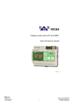
Control unit HC64
Control unit HC64 keeps setting of regulation schedules for up to 32
independent heating circuits. It is possible to set up to 8 different temperature
changes in one day, at any time and for any value. Part of the control unit
delivery is also power supply 24V AC / 2,5A. It supplies control unit, thermostatic
sensors and actuators operated by sensors.
Control unit has two operation modes. User mode, which allows displaying room
temperature, defining temperature profile, etc. Service (administrator) mode,
protected by password, which is supposed to be used for fundamental setting of
heating system, for example number of circuits, communication parameters and
temperature calibration for every sensor.
More information, operation and setting of HC64 can be found in technical documentation of HC64.
Control unit must be placed on common three-wires bus network to the place where the user will make all actions. If
the system is equipped by PC, it can be actually placed on any even invisible place. Personal computer can be
connected to the control unit via USB or Ethernet interface.
2.2.2.
Power switching unit
Regulation unit gets requested temperature value for appropriate heating
circle at defined time from control station. Real temperature of the room or
floor temperature is being found out by connected sensors. For RT control
system two types of temperature sensors are available:
• Analogue temperature sensors. Temperature sensors which are
connected via two-wires line directly to control station.
• Digital temperature sensors. Sensors are connected via three-wire line
(24V (+), (-) and communication line L). Sensors are intelligent and have
additional functions.
Real temperatures are compared with requested values and according to the
results appropriate power semiconductor elements are controlled. Heating
devices are directly operated by semiconductor switches.
Control process by power semiconductor switches is absolutely silent and
does not generate any disturbances into the network. Another very important
advantage is high switching rate (lifetime doesn’t depend on the number of
operations) which assures excellent accuracy of regulation. Heating device is
being regulated to provide exact heating power in order to keep the requested temperature. This operation saves
BMR trading
Horní lán 17
779 00 Olomouc
Czech Republic
5
Tel: +420 778 066 566
[email protected]
www.bmr-trading.com
Development and production of systems for measurement and control
consumed energy and reduces the cost of the heating.
Note
MCB and RCB are not a part of delivery. Nevertheless the case of power control unit is ready for their installation.
Note
Power control unit is delivered in white color RAL9003 in three dimensions according the number of power channels:
• RT04 – RT08 max. 15kW (width x high x depth 520 x 470 x 90 mm, concealed frame 550 x 660 x 150 mm)
• RT09 – RT16 max. 30kW (width x high x depth 585 x 770 x 90 mm, concealed frame 620 x 960 x 150 mm)
• RT17 – RT32 max. 60kW (width x high x depth 820 x 770 x 90 mm, concealed frame 855 x 960 x 150 mm)
Detail dimensions of RT cases:
Picture No.1 Dimensions of RT04 – RT08
Picture No.1 Dimensions of RT04 – RT08
BMR trading
Horní lán 17
779 00 Olomouc
Czech Republic
6
Tel: +420 778 066 566
[email protected]
www.bmr-trading.com
Development and production of systems for measurement and control
BMR trading
Horní lán 17
779 00 Olomouc
Czech Republic
7
Tel: +420 778 066 566
[email protected]
www.bmr-trading.com
Development and production of systems for measurement and control
Picture No. 2 Dimensions of RT09 – RT16, RT17 – RT32
BMR trading
Horní lán 17
779 00 Olomouc
Czech Republic
8
Tel: +420 778 066 566
[email protected]
www.bmr-trading.com
Development and production of systems for measurement and control
2.2.3.
Analogue temperature sensors
Analogue temperature sensors are available in two designs for floor temperature measurement and air temperature
measurement.
RT_L
Sensor is designed to be placed on
the inner wall to the high of 120 – 150
cm. It is produced only in blind design
and it is possible be mounted on
recessed box KU 68 or surface
mounted box which can be supplied
together with sensor.
RT_P
Sensor is designed for floor
temperature measurement and it is in
the shape of metal roller with diameter
of 6mm and length of 20 mm. Due to
the fact that in the floor heating it is
very important not to exceed maximum
allowed temperature, it is necessary to
place this sensor on the best place,
considering the floor type, in order to
measure directly the floor temperature
or temperature of heating medium.
Analogue air-sensors RT_L are available at the same designs as HTS64 sensors. Other designs on the request.
Important
All sensors measure with accuracy 1ºC. This accuracy is absolutely sufficient for measurement of room temperature.
Nevertheless sensor can be calibrated on higher accuracy.
BMR trading
Horní lán 17
779 00 Olomouc
Czech Republic
9
Tel: +420 778 066 566
[email protected]
www.bmr-trading.com
Development and production of systems for measurement and control
2.2.4.
Digital temperature sensors
Air sensors HTS64 range are digital thermostats with a built-in temperature sensor which communicate with the
control unit HC64 for to get the information about the targeted temperature in the particular circuit. It also
communicates directly to power switching unit to control direct electric heaters in particular circuits.
On the contrary it provides information about the measured temperature and actuator status to control unit.
According to a customer specification three types of sensors can be offered:
HTS64
HTS64D
Basic type of sensor.
HTS64DN
Sensor with LCD which shows current
temperature and actuator status.
Sensor with LCD and buttons. Display
shows current temperature and
actuator status. Unit is equipped with
buttons for local temperature setting.
Locally set temperature is kept until
next temperature change according to
the regime.
Sensors are available in several designs of case in order at to fit the style of the other elements used in the house.
Following designs are available.
Manufacturer / type
HTS64
HTS64D
HTS64DN
ABB
Element
●
●
●
ABB
Time
●
●
●
ABB
Tango
●
●
●
ABB
Tango
●
●
●
ABB
Neo
●
●
●
ABB
Swing
●
●
●
ABB
Classic
●
●
●
Schneider
Unica Basic
●
●
●
Schneider
Unica Color
●
●
●
Schneider
Unica Top
●
●
●
Schneider
Unica Quadro
●
●
●
Legrand
Cariva
●
●
●
Legrand
Valena
●
●
●
Important
All sensors measure with accuracy 1ºC. This accuracy is sufficient for measurement of room temperature. Nevertheless
sensor can be calibrated on higher accuracy.
BMR trading
Horní lán 17
779 00 Olomouc
Czech Republic
10
Tel: +420 778 066 566
[email protected]
www.bmr-trading.com
Development and production of systems for measurement and control
2.3. Optional accessories
2.3.1.
RTR concealed frame
Power control units are produced in three sizes. Smallest size can control heating
system maximally in 8 circuits, medium size in 16 circuits and biggest size in 32
circuits. All three sizes are by standard mounted on the wall surface. For all three
types the special concealed frame is offered. This frame allows power control unit
be recessed into the wall. Special frame is needed due to better cooling of power
semiconductors.
2.3.2.
RT_5kW
Standard semiconductor switching element in power unit is designed for operation of heater up to 3 kW. In case that
is necessary operated the higher power there is module RT_5kW which allows to operate heaters up to 5 kW. This
request is necessary note at order specification.
2.3.3.
LOW modem
LOW_MODEM allows switch the regulator over, from comfortable heating mode to the saving mode (“LOW” mode)
and back by logical signal applied to the low modem inputs.
Function description:
• Red LED on – module in the operation.
• Green LED off – terminals No. 4 – 5 closed, control section heats according to set mode.
• Green LED on – terminals No. 4 – 5 opened since GSM gate gives signal for control section and it switches to the
LOW mode.
Note
Low is connected to the system on the same bus as other items. Once the LOW_MODEM is installed into the system, it is
possible to control mode changes only by SMS GSM gate. Manual switching on control section is disabled. For enabling the
manual changes of LOW mod, power supply of LOW_MODEM must be disconnected.
2.3.4.
WTR01 roof windows warming
Unit WTR01 has input for measuring of outdoor temperature which it compares with set temperature in control unit. If
the outdoor temperature is lower than set temperature it switches relay which operates all heating foils installed
under the roof windows.
Information about outdoor temperature is shown on sensors HTS64D and HTS64DN. On the display of sensor the
outdoor temperature is temporarily shown for short time while main information is still indoor room temperature.
WTR01 unit is connected to the bus No. 2 by the same way as HC64 control unit.
2.3.5.
Window contact
Window contact OK_NET provides information about the window status (open/close) in
the controlled room. It is connected directly to the sensor and includes reed contact, which
reacts on the closeness of the permanent magnet. Contact itself is mounted on the
window frame and magnet is fixed on the window. If the window is open, then
programmable thermostat disconnects appropriate circuit over the actuator and set 8ºC as
a target temperature in the room.
If the room temperature drops below 8ºC, programmable thermostat opens actuators
(protection against low temperature in the room).
2.4. Design and installation of regulation system
Installation of regulation system is easy and logical. If the operation steps are followed it should be without any
complication working on the first connection.
Design procedure:
1. Define placement and the number of analogue sensors. All analogue sensors are connected in the spider
BMR trading
Horní lán 17
779 00 Olomouc
Czech Republic
11
Tel: +420 778 066 566
[email protected]
www.bmr-trading.com
Development and production of systems for measurement and control
network (spoke wisely). From every sensor pair-wire comes directly to regulator (central station). Recommended
cables are SEKU 2x0,8 or SYKY and SYKFY 3x2x0,5. Paralleling with power line is not forbidden. Shielding is not
required.
2. Define placement and the number of digital sensors. Digital sensors are connected into the bus network.
Devices are connected in parallel one by one via three wires line. Used cable has to be in shielded design, for
example SYKFY 3x2x0,5. Shielding is connected at every sensor and central station with power supply negative
(-) terminal. Paralleling with power line is not allowed.
3. Specify heating system parameters in the order. Control station is programmed according to the heating
system configuration and it is impossible those parameters changed on place of installation. Installation user
guide and parametrization of the regulator is placed inside the door of every RT power control unit. Installer has to
precisely follow connection diagram otherwise regulator will not work properly.
4. Specify additional information about the system and request. Mainly requests for usage of end item, LOW
modem, software, system combination etc.
5. names or numbers of rooms
6. for every room sensor type specification (analogue or digital and type) or combination of sensors for example
floor and air sensor.
7. Expected power consumption of heater in kW.
8. Assure power supply cables dimension from heaters to RT control unit and their protection. For heaters is
necessary to use cables with diameters exactly according to standards.
9. Assure unblocked power supply.
10. Assure Centralized Ripple Control supply of control “Zero” from utility switching device placed in the main
switchboard.
11. Provide additional information. Mainly requests for modem, software, regulation combination usage etc.
According to above listed information the type of regulation connection diagram is selected. Connection diagrams are
annexed to this document.
Important
It is very important to design system with attention on minimization of power supply and communication length and
minimization of power loses on this line.
Control section is placed directly inside the regulator (power control unit) but it can be installed independently on the
wall. For external mounting of control section use the same cable as for digital temperature sensors. Control section
can be installed up 300 m from the regulator (power control unit).
If for larger installations, temperature sensors do not communicate well with control section and connection is correct
and verified, modify the communication line by connecting additional resistor of 1,5 k Ω. Resistor is connected
between the terminal (-) and communication line (L).
It is recommended to consider usage of current limiting device HJ303 or HJ306. That device allows to decrease main
circuit breaker about 2 stages. Connection diagram of current limiting device HJ in the RT system is shown on the
enclosed connection diagrams at the appendix.
For the temperature sensors placement follow the same rules as for thermostats of RNET system.
By observing all above listed rules, system installation will not be giving any complication and system will fully work
on the first start.
2.4.1.
Lowering the MCB value
It is possible installed the current limiter HJ303 or HJ306 into the RT64 system. In case of correct usage it allows to
reduce the value of main MCB about 2 levels. HJ device monitors the phase current in all three phases and indicates
its rise over the limit by disconnection of appropriate relay output.
2.4.2.
Underfloor heating control
RT system is possible use for control of underfloor heaters such as foils and mats. For measuring of floor
temperature there is analogue floor sensor RT_P. If the rooms are heated only by electric underfloor heaters then one
floor sensor is installed for each circuit. This floor sensor then controls maximum temperature of the floor. Also air
BMR trading
Horní lán 17
779 00 Olomouc
Czech Republic
12
Tel: +420 778 066 566
[email protected]
www.bmr-trading.com
Development and production of systems for measurement and control
sensors are installed which measures the air temperature in the rooms and controls the particular power channels to
reach the requested ambient temperature.
In case that there is combined system with convectors and underfloor heaters in the room it is possible configured RT
system so that air-sensor controls either power channel for convectors and either power channel for underfloor
heaters.
2.4.3.
Recommendation for sensor installation according to type of room
1. Vestibules – if the vestibule is heated by underfloor mat then it is used only floor sensor RT_P which has
assigned special temperature regime, for example 19°C. Air sensor is not used since it will switch heater in vain
on temporary short temperature changes when main door is opened.
2. Corridors – in corridors with underfloor heating mats with tiled floor the only air sensor is used. At such type of
floor the overheating is not a issue and underfloor sensor RT_P is not necessary to be used.
3. Living rooms with several independent circuits – for each circuit (power channel) there is independent floor
sensor RT_P. Then for whole room there is one air sensor (recommended HTS64_DN) which measures
temperature in the room and controls all circuits. All floor sensors have set one regime, for example 25°C
(maximum floor temperature). Air sensor has a normal regime so then the room temperature is controlled
according to air sensor which is reacting on every temperature change in the room (people move, open doors
etc.) and according to request it switch on/off all circuits (power channels) at the same time. If there will be more
air sensors in the room then unpleasant effect will appear by different floor temperatures at particular circuits.
4. Bathrooms – for the bathrooms there is recommendation to install underfloor mat controlled by floor sensor
RT_P with its own regime. If the electric ladder for towels drying is installed the it is connected to RT as a sole
circuit. Ladder is controlled by air sensor, typically HTS64_DN with local temperature change possibility. By this
the possibility to increase the ladder temperature to dry towels. Turning the ladder off is according to assigned
appropriate regime.
2.4.4.
Important instruction for installation
Before installation itself please read carefully following basic instructions:
1. Regulator RT is electrical device, which can be installed only by person with appropriate electro-technical
qualification and approved certification from BMR for installation of RT systems. Installation provided by
unauthorized person cannot be covered by warranty.
2. RT device is classified as a regulator. It is not classified as an electrical switchboard.
3. Regulator is configured by producer according to the customer requests and therefore it is impossible to make
changes lately like, for example number of power channels or sensors. If the change is needed please contact
producer.
4. Regulator is delivered without MCBs and RCBs. Positions on DIN rail are reserved, in preference, for MCBs.
5. RCBs have to be installed if heating cable without conductive braiding is used. The heating cable with conductive
braiding and RCB has to be used in the bathrooms. RCB has to have nominal trigger current up to 30 mA. For
heating cables RCBs have to be installed for every channel independently. For heating foils one three-phase RCB
can be used for all channels.
6. Installer is not allowed to modify or even work on regulation part of the RT system!
7. Regulator (power control unit) must not be placed outdoor or wet place!
8. Ventilating aperture must not be covered by anything. Without the producer knowledge and permission, the
regulator (power control unit) must not be installed into the parent switchboard.
9. Power supply and remote ripple control has to be from the same phase!
10. Into the regulator the signal wire from remote ripple control has to be connected.
11. Any actions on the regulator connection have to be operated only under disconnect regulator (power control unit).
12. All channels and sensors have to be connected exactly on the right positions according to the room list and
connection diagram which a part of delivery and it is enclosed in the regulator.
13. Regulator RT must not be used for power switching via relays! Power channels are directly switching by
semiconductors in the regulator (power control unit).
14. Keep the regulator without any action for about 10 minutes after power supply connection. Device is doing initial
BMR trading
Horní lán 17
779 00 Olomouc
Czech Republic
13
Tel: +420 778 066 566
[email protected]
www.bmr-trading.com
Development and production of systems for measurement and control
communication with control section and temperature sensors. Every action on the control section prolongs that
initial communication.
15. User manual and service manual is available for installer. Service manual should not be available for end user.
16. RT system is maintenance less, except regular revisions.
2.5. Technical features
Parameter
value
Supply voltage
3 x 400 VAC / 50 Hz
Maximum power of standard switching channel
3 kW
Maximum power of tuned switching channel
5 kW
Power consumption of control unit
0,3 VA
Power consumption of temperature sensor
0,2 VA
Power consumption of LOW modem
0,2 VA
Maximum number of independently controlled channels RT
32
Control bus for digital sensors
+, -, L (24 VDC)
Temperature measurement range
-10 to 50°C
Temperature measurement accuracy
1°C
Date and time backup
24 hours
Configuration backup
10 years
3. HC64 communication possibilities
Control unit HC64 has communication interfaces such as USB and RJ64 Ethernet. Part of delivery is the
communication software Heating Management Software HMS64. HMS64 allows configure the complete system and
set all regimes and settings. HC64 has also build web server for device operation over the web browsers which
support HTML5.
3.1. USB connection
Connection over USB is via standard connector of the B type. Communication protocol is according to standard HID
(Human interface device) so there is no need for any converter or driver. Communication cable is a part of HC64
delivery.
3.2. Ethernet connection
HC64 has integrated RJ45 interface for connecting of IPv4 10/100Mbit/s network. Control unit has implemented two
network services accessible on defined TCP ports.
For connection to existing network it is mandatory set following parameters.
1. IP address (default value 192.168.1.113)
2. Mask (default value 255.255.255.0)
3. Gateway (default value 0.0.0.0)
4. TCP port of web server (default value 80)
5. TCP port of Modbus service (default value 502)
Warning
The DHCP server is not possible be used for obtaining the IP address. Address has to be set manually and hast to be fixed.
BMR trading
Horní lán 17
779 00 Olomouc
Czech Republic
14
Tel: +420 778 066 566
[email protected]
www.bmr-trading.com
Development and production of systems for measurement and control
3.2.1.
Web interface
Web interface is essential way of heating system operation. Access to the web page of HC64 is via setting its IP
address to the web browser with support of HTML5.
Access is protected by user name and password. Web server is without a part of service settings in order to avoid
unauthorized operations.
The web server is platform independent but there might be some devices without appropriate support. For more
information contact producer.
3.2.2.
Modbus TCP interface
Modbus TCP interface is used for communication with HMS64 software over the TCP/IP. Modbus protocol is a
standardized industrial protocol for data transmission.
4. Application examples
4.1. Direct electric convection heating
For heating based on wall mounted convection heaters and ceiling infrared panels or foils the configuration of RT
system requires only air sensors.
BMR trading
Horní lán 17
779 00 Olomouc
Czech Republic
15
Tel: +420 778 066 566
[email protected]
www.bmr-trading.com
Development and production of systems for measurement and control
4.1.1.
Installation example
Channel
Description
Heater type
1
Vestibule + WC (room 0.1 + room 0.2)
convection heater
RT_L
2
Bathroom (room 0.3)
convection heater
HTS64DN
Kitchen (room 0.4)
convection heater
Living room + corridor (room 0.5)
convection heater
4
Bedroom 1 (room 0.6)
convection heater
HTS64D
5
Bedroom 2 (room 0.7)
convection heater
HTS64DN
6
Bedroom 3 (room 0.8)
convection heater
HTS64D
3
Floor-sensor
Air-sensor
HTS64DN
Vestibule and WC are grouped together to be controlled by one channel No. 1. Therefore the rooms 0.1 and 0.2 have
common air-sensor. It is chosen analogue type since there is no need for displaying the local temperature.
Bathroom (room 0.3) has only ladder heater which is controlled by channel No. 2 and it has digital air-sensor with
LCD and buttons for local temperature setting.
Kitchen (room 0.4) and living room (room 0.5) are on one channels and with one digital air-sensor with LCD and
buttons. They are considered as one large room.
Bedroom 1 is with digital sensor without buttons to avoid kids to play with. It is planned to be changed in future to
HTS64DN.
Bedroom 2 is with digital sensor with buttons.
Bedroom 3 is with digital sensor without buttons to avoid kids to play with. It is planned to be changed in future to
HTS64DN.
The complete RT system is based on RT06 power switching unit, HC64 control, 5 digital air-sensors and 1 analogue
air-sensor.
4.2. Underfloor heating
System RT64 can control also electrical floor heating systems based on heating mating and foils. This case the
analogue floor sensor RT_P has to be used for protection against overheating the floor. Analogue floor sensors are
connected directly to the power switching unit RT64. Air sensors can be digital or analogue type depending on the
usage requirements.
4.2.1.
Installation example
It is the same building but with direct electric underfloor heating. The main difference is that each floor have analogue
floor-sensor as a protection against overheating.
Channel
Description
Heater type
Floor-sensor
Air-sensor
1
Vestibule + WC (room 0.1 + room 0.2)
mat
RT_P
RT_L
2
Bathroom floor (room 0.3)
mat
RT_P
3
Bathroom ladder (room 0.3)
ladder
4
Kitchen (room 0.4)
mat
RT_P
5
Living room + corridor (room 0.5)
foil
RT_P
6
Bedroom 1 (room 0.6)
foil
RT_P
HTS64D
7
Bedroom 2 (room 0.7)
foil
RT_P
HTS64DN
8
Bedroom 3 (room 0.8)
foil
RT_P
HTS64D
HTS64DN
HTS64DN
Vestibule and WC are grouped together to be controlled by one channel No. 1. The mats are connected together. The
rooms 0.1 and 0.2 have common air-sensor. It is chosen analogue type since there is no need for displaying the local
temperature.
Bathroom (room 0.3) is controlled by two channels where first is for mat in the floor and it is used as a main source. It
is controlled by analogue floor-sensor to assure that floor will have always comfort temperature. Second channel is
used only for ladder and it is controlled by digital air-sensor with LCD and buttons.
Kitchen (room 0.4) and living room (room 0.5) are on separate channels because of different heaters. In the kitchen
BMR trading
Horní lán 17
779 00 Olomouc
Czech Republic
16
Tel: +420 778 066 566
[email protected]
www.bmr-trading.com
Development and production of systems for measurement and control
there is mat (tail floor) and in the living room foil. Nevertheless they have common digital air-sensor with LCD and
buttons.
Bedroom 1 is with digital sensor without buttons to avoid kids to play with. It is planned to be changed in future to
HTS64DN.
Bedroom 2 is with digital sensor with buttons.
Bedroom 3 is with digital sensor without buttons to avoid kids to play with. It is planned to be changed in future to
HTS64DN.
The complete RT system is based on RT08 power switching unit, HC64 control, 7 analogue floor-sensors, 1
analogue air-sensor and 5 digital air-sensors.
BMR trading
Horní lán 17
779 00 Olomouc
Czech Republic
17
Tel: +420 778 066 566
[email protected]
www.bmr-trading.com
Development and production of systems for measurement and control
5. Connection diagrams
5.1. Connection of RT system
BMR trading
Horní lán 17
779 00 Olomouc
Czech Republic
18
Tel: +420 778 066 566
[email protected]
www.bmr-trading.com
Development and production of systems for measurement and control
5.2. Connection of HJ controller to RT power switching unit
Cooperation of HJ controllers and regulator RT is based on the disconnection of analogue sensors from the regulator
(power control unit). When analogue sensor is disconnected by HJ controller, regulator disconnects appropriate
circuit too. For analogue sensors disconnection is necessary to use wire coming from terminal PLUS because
terminal PLUS is common for group of 8 sensors. In case of grouped sensors it is possible to disconnect whole group
by one HJ contact.
If two analogue sensors are used in the system (floor sensor and and air sensor) for one room, only the floor-sensor
has to be disconnected.
BMR trading
Horní lán 17
779 00 Olomouc
Czech Republic
19
Tel: +420 778 066 566
[email protected]
www.bmr-trading.com
Development and production of systems for measurement and control
5.3. Connection and setting of digital sensors ID
BMR trading
Horní lán 17
779 00 Olomouc
Czech Republic
20
Tel: +420 778 066 566
[email protected]
www.bmr-trading.com