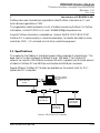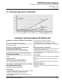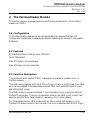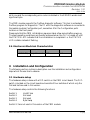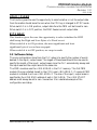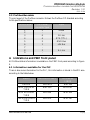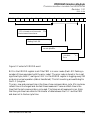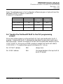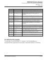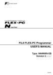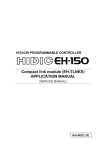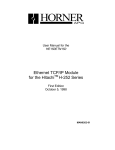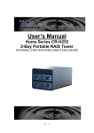
1
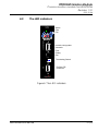
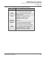
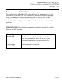
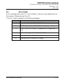
User Manual
Profibus Master
Module
STATUS
COM
FAIL
Doc. No. H252H252- PDPMPDPM- 1.31
BUS
ON
ERROR
READY
RUN
CONFIGURATION
PROCESS FIELD BUS
HMS FIELDBUS SYSTEMS AB
PILEFELTSGATAN 93-95
SE-302 50 HALMSTAD, SWEDEN
PHONE: +46 35 17 29 00
FAX: +46 35 17 29 09
www.anybus.com Ÿ [email protected]
AnyBus© Communication Systems
PROFIBUS Master Module
Communication module for H252PDPM
Revision 1.31
1999-12-04
Table of Contents
1.1
1.2
Specifications
Technical Features for Profibus-DP
2.
The PROFIBUS Master Module
2.1
Configuration
2.2
Features
2.3
Function Description
2.4
Electronics Electrical Characteristics
3.
Installation and Configuration
3.1
Hardware setup
3.2
Software Setup
3.3
Profibus Bus-cable
4.
Indications and PBM front panel
4.1
Information available for the PLC
4.2
The LED indicators
4.3
Termination
4.4
Error Codes
5.
Programming the PBM
5.1
Make a map over the Profibus-DP Network.
5.2
Installing the PBM-module.
5.3
Configuring the Profibus-DP Master.
5.4
Transfer the Profibus-DP MAP to the PLC programming
project.
5.5
Write the PLC program.
HMS FIELDBUS SYSTEMS AB
3
4
5
5
5
5
6
6
6
7
8
8
8
10
12
13
14
14
14
14
15
16
2 (16)
PROFIBUS Master Module
Communication module for H252PDPM
Revision 1.31
1999-12-04
1.
Introduction of PROFIBUS-DP
Profibus has a user international organisation called Profibus International, PI, and
local national organisations, PNO.
The organisation assists members on a lot of matters concerning Profibus. For further
information, contact PI/PNO on E-mail: [email protected].
General Profibus information is available on Internet: WWW.PROFIBUS.COM.
Profibus-DP is used normally in industrial automation, to transfer fast data for motor
controllers, MMI, I/O units and a lot of other industrial equipment.
1.1 Specifications
The media for the fieldbus is a shielded copper cable composed of a twisted pair. The
baud rate for the bus is between 9.6kbaud to max. 12Mbaud. The Profibus-DP
network can consist of 32 different modules (126 with a repeater) and the total amount
of data for Profibus-DP are 246 Byte out/module and 246 Byte in/module.
Several different Profibus-DP Masters are available on the market, both for PLCsystems and PC computers
PROFIBUS DP
Personal Computer
with Configuration
Software
RS-232
Master
DP
Profibus DP
Slave node #1
Profibus DP
Slave node #n
Profibus DP
Slave node #2
Picture 1: PROFIBUS-DP Overview
HMS FIELDBUS SYSTEMS AB
3 (16)
PROFIBUS Master Module
Communication module for H252PDPM
Revision 1.31
1999-12-04
1.2 Technical Features for ProfibusProfibus- DP
Picture 2: Bus cycle time of a Profibus-DP Mono Master system
Summary Technical Features PROFIBUSPROFIBUS- DP
Transmission Technique: PROFIBUS DIN 19245 Part
1
-EIA RS 485 twisted pair cable or fibre optic
-9.6 kbit/s up to 12 Mbit/s, max. distance 200m at 1.5 Mbit/s
extendible with repeaters
-Synchronization of inputs and/or outputs
Address assignments for the DP-Slaves over the bus
Configuration of the DP-Master (DPM1) over the bus
max. 246 bytes input and output data per DP-Slave, typical 32
bytes
Medium Acces: hybrid medium access protocol
according to DIN 19245 Part 1
-Mono-Master or Multi-Master systems supported
-Master and Slave Devices, max. 126 stations possible
Security and protection mechanisms:
-All messages are transmitted with Hamming Distance HD=4
-Watch-Dog Timer at the DP-Slaves
Access protection for the inputs/outputs at the DP-Slaves
-Data transfer monitoring with configurable timer interval at the
DP-Master (DPM1)
Communications: PeerPeer- toto- Peer (user data transfer) or
Multicast (synchronisation)
-Cyclic Master-Slave transfer and acyclic Master-Master data
transfer
Operation Modes
- Operate: cyclic transfer of input and output data
-Clear: inputs are read and outputs are cleared
-Stop: only Master-Master functions are possible
Device - Types:
-DP-Master Class 2 (DPM2) e.g. programming/ configuration
device
DP-Master Class 1 (DPM1) e.g. central controller like PLC,
CNC, RC …
DP-Slave e.g. Input/Output device with binary or analogue
inputs/outputs, drives …
Synchronization: enables synchronization of the inputs Cabling and Installation:
and/or outputs of all DPDP- Slaves
-Connecting or disconnecting of stations without affection of
-Sync-Mode: Outputs are synchronized
other stations
-Freeze-Mode: Inputs are synchronized
Functionality:
-Cyclic user data transfer betwen DP-Master(s) and DP-Slave(s)
-Activation or deactivation of individual DP-Slaves
-Checking of the configuration of the DP-Slaves
-Powerful diagnosis mechanisms, 3 hierarchical levels of the
diagnosis messages
HMS FIELDBUS SYSTEMS AB
4 (16)
PROFIBUS Master Module
Communication module for H252PDPM
Revision 1.31
1999-12-04
2. The P ROFIBUS Master Module
This section contains a general technical and functional description of the Profibus
master unit (PBM).
2.1 Configuration
The Profibus master module can be configured using the external Profibus-DP
Configurator (please refer to separate documents regarding the external Configuration
Software).
2.2 Features
All Baud rates from 9.6 kbit/s up to 12 Mbit/s
Up to 124 stations
Max. 512 bytes in of process data
Max. 512 bytes out of process data
2.3 Function Description
The Profibus Master module (PBM), is designed to operate as a master unit in a
Profibus network.
The PBM works together with the H252 unit from Hitachi in a BSH base. Two PBM
units can be installed in the same base and each PBM can handle 512 bytes of input
and 512 bytes of output.
The PBM is easy to use and configure. The configuration is done using the external
Profibus Configurator. The only configuration done on the PBM is the ”Hold/Clear”
selection and the ”Byte Swap” selection, see section 3 for further details.
For the programmer the PBM module will act like a normal link module, i.e. the
Profibus I/O-data is stored in the link area. If an error is detected the ERROR-flag is
HMS FIELDBUS SYSTEMS AB
5 (16)
PROFIBUS Master Module
Communication module for H252PDPM
Revision 1.31
1999-12-04
set to one and the corresponding error code is indicated in the ERROR-words most
significant byte.
The PBM module supports the Profibus diagnostic software. This tool is a standard
Profibus program for diagnostics. The PC with the diagnostics software is connected to
the master modules Configurator port, see section 4 for the Configuration ports
location on the front panel.
Please note that the PBM initialisation sequence takes a few seconds after power up.
The best operating conditions are therefor achieved when the PLC is turned off until
the STATUS LED indicates that the initialisation is completed. I.e. the STATUS
LED is stable instead of flashing.
2.4 Electronics Electrical Characteristics
Symbol
Description
Type.
Unit
I (VCC 5V)
Input Current
600
mA
3. Installation and Configuration
The following section contains a description over the installation and configuration
steps which the user has to observe.
3.1 Hardware setup
The hardware setup is done with a DIP-switch on the PBM circuit board. The DIPswitch is located on the circuit board and consists of four switches of which only the
first and last are used in this version.
The hardware setup controls the following functions:
Switch 1.
Switch 2.
Switch 3.
Switch 4.
Hold/Clear
Not used
Not used
Byte Swap
Switch 2-3 are not used in this version of the PBM module.
HMS FIELDBUS SYSTEMS AB
6 (16)
PROFIBUS Master Module
Communication module for H252PDPM
Revision 1.31
1999-12-04
HOLD / CLEAR
This function gives the user the opportunity to select whether or not the output data
from the master should be set to zero when the CPU key is changed to STOP mode.
When switch 1 is in ON position, output data from the PBM will be forced to zero.
When switch 1 is in OFF position, the PBM freezes current output data.
BYTE SWAP
This function gives the user the opportunity to select whether the H252
shall swap the High and Low-Bytes of a Word or not.
When switch 4 is in ON position, the most significant and least
significant byte of a word are swapped.
When switch 4 is in OFF position, no swap is made.
3.2 Software Setup
The only configuration done from the PLC setup is to specify the number of words
desired in the input / output areas. The largest of these areas should then be used to
specify the length of the input / output areas, since the PLC automatically always sets
the input area and the output area to the same size.
The PBM modules uses the LINK AREAS in the PLC memory. The first PBM
module (the one installed closest to the CPU) uses LINK AREA 1. If a second PBM
module is installed it will use LINK AREA 2. The size of the input / output areas is
specified by the LINK END address of each LINK AREA. The LINK START
address must always be set to zero. See section 5 for a detailed example of the
configuration and setup.
HMS FIELDBUS SYSTEMS AB
7 (16)
PROFIBUS Master Module
Communication module for H252PDPM
Revision 1.31
1999-12-04
3.3 Profibus BusBus- cable
The pin layout of the Profibus connector follows the Profibus-DP standard according
to the specifications below:
Pin in D-SUB
1
2
3
4
5
6
7
8
9
Pin in other
connector types
5
4
6
2
1
3
-
Signal
Shield
B-Line
RTS (TTL)
GND Bus
+5V Bus
A-Line
-
4. Indications and PBM front panel
All Profibus status information is available on the PBM front panel according to figure
4.
4.1 Information available for the PLC
There is also some information for the PLC, this information is stored in the WR area
according to the table below:
NAME
ADDRESS LINK 1
ERROR
MAX REFRESH
TIME
MIN REFRESH
TIME
PREVIOUS REFR.
TIME
WRF0F9
WRF13D
ADDRESS
LINK2
WRF159
WRF19D
WRF13E
WRF19E
WRF13F
WRF19F
HMS FIELDBUS SYSTEMS AB
8 (16)
PROFIBUS Master Module
Communication module for H252PDPM
Revision 1.31
1999-12-04
ERROR
15
14
13
12
11
10
Error on remote address:
- FEh = Lowest no of error node
Device has an internal error
9
8
7
6
5
4
3
2
1
0
00h
FFh =
Error-code, same as indicated by
flashing Red LED.
Watchdog toggles every 250 ms during
normal operation.
Error present flag: 0
= No error
1=
Error
Figure 3. Content of ERROR-word
Bit 0 in the ERROR register is set if the PBM is in error-mode (Red LED flashing a
number of times equivalent with the error-code). The error-code is stored in the Least
significant byte, bits2-7, see figure 3. Bit 1 in the ERROR register is toggling every 250
ms during normal operation (data is transferred). This bit is working as a watchdog for
the PLC-program.
The min, max and previous time is the time of one communication cycle. Min and max
refresh time is the longest and shortest times measured. Previous refresh time is the
time that the last communication cycle used. The times are all measured in ms. Note
that the cycle time here refers to the transfer of data between the PLC and the PBM
and does not to the bus cycle time
HMS FIELDBUS SYSTEMS AB
9 (16)
PROFIBUS Master Module
Communication module for H252PDPM
Revision 1.31
1999-12-04
The LED indicators
STATUS
COM
FAIL
4.2
Status
Com
Fail
CONFIGURATION
PROCESS FIELD BUS
BUS
ON
ERROR
READY
RUN
Profibus configurator
connector
Error
Ready
Run
Terminating Switch
Profibus DP
connector
Figure 4. The LED indicators
HMS FIELDBUS SYSTEMS AB
10 (16)
PROFIBUS Master Module
Communication module for H252PDPM
Revision 1.31
1999-12-04
The LED’s (Light Emitting Diodes) indicates the following:
LED
STATUS
Function
Flashing: The module is initialising.
Lit: Profibus Master Module is ready.
COM
PLC is running and the module is
transferring data.
FAIL
Flashing: The number of flashes
separated by a longer delay, is
equivalent to the error code.
ERROR
Bus Error.
READY
Lit: The master-part of the module
is Ready to communicate. Flashing:
New configuration is being downloaded.
RUN
HMS FIELDBUS SYSTEMS AB
Lit: The device is transferring data to
the Profibus Network. Flashing:
Initialising the Profibus network..
11 (16)
PROFIBUS Master Module
Communication module for H252PDPM
Revision 1.31
1999-12-04
4.3
4.3
Termination
The end nodes in a Profibus-DP network has to be terminated to avoid
reflections on the bus line. The Profibus-DP master module is equipped
with a termination switch to accomplish this in an easy way. If the
module is used as the first or last module in a network the termination
switch has to be in ON position. Otherwise the switch has to be in OFF
position.
PLEASE NOTE: If an external termination connector is used the switch
must be in OFF position.
Termination
switch ON
Bus termination enabled
Termination
switch OFF
Bus termination disabled
HMS FIELDBUS SYSTEMS AB
If the module is the last or first module,
the bus termination has to be set on, or an
external termination connector has to be
used
12 (16)
PROFIBUS Master Module
Communication module for H252PDPM
Revision 1.31
1999-12-04
4.4
4.4
Error Codes
Error is indicated when the FAIL-LED is flashing. The error code is determined by
the number of flashes done by the LED.
The Error Codes correspond to the following messages:
Error Code Type of Error
1
Failed to initialise Profibus-DP Master.
2
Start Address of the LINK AREA in the PLC is not zero.
3
LINK LENGTH of the PLC equals zero or is larger than FF
Hex.
4
Slot is not configured as LINK in the PLC.
5
Communication with PLC failed.
6
Internal Error on Profibus-DP Master.
HMS FIELDBUS SYSTEMS AB
13 (16)
PROFIBUS Master Module
Communication module for H252PDPM
Revision 1.31
1999-12-04
5. Programming the PBM
The following section contains a simple step by step guide about how to use the PBM
in a project.
5.1 Make a map over the ProfibusProfibus- DP Network.
The first step is to document (Map) the Profibus-DP system in the application. Doing
so the number of input and output words will be given. If either the input area or the
output area exceeds 255 words, two separate Profibus networks have to be used.
Hitachi PLC
P
W
R
C
P
U
P
B
M
HMS PB 64-I/O
OP. Panel
Servo
Slave Unit 1
Slave Unit 2
Slave Unit 3
2 output
words 2
input words
4 input
words
3 output
words
5.2 Installing the PBMPBM- module.
The PBM module fits in a BSH base with a H252 Hitachi CPU. The only hardware
set-up done on the PBM circuit is the ”Hold/Clear” configuration described above. If
two PBM modules are installed in the same base, the PBM module closest to the CPU
will operate on LINK AREA 1 and the second will operate on LINK AREA 2.
5.3 Configuring the ProfibusProfibus- DP Master.
Use the Profibus-DP configurator port to configure the Profibus-DP network. Write
down on which addresses the different modules input and output words are mapped.
Also make sure that the network node addresses match with the ones designated to the
modules.
HMS FIELDBUS SYSTEMS AB
14 (16)
PROFIBUS Master Module
Communication module for H252PDPM
Revision 1.31
1999-12-04
Note: The addresses given in the Configurator software are given in byte units and the
addresses in the PLC is given in word units.
Example of Configuration:
Node Name
Node Address
Input Area Output Area
(bytes)
(bytes)
HMS PB 64-I/O
02
0-3
0-3
OP. Panel
03
4-11
-
Servo
04
-
4-9
5.4 Transfer the ProfibusProfibus- DP MAP to the PLC programming
project.
When the Profibus system is configured the MAP has to be transferred to the PLC
program. Observe that the PLC automatically dedicates the same size to both input
and output areas. Therefor the largest of the two has to be used when determining the
LINK LENGTH. Since only one PBM module is needed it will work with data in
LINK AREA 1. The system above gives the following PLC set-up:
WL1 START address:
00H
(always zero)
WL1 END address:
05H
(the largest address is the input with 6
words (12 bytes))
HMS FIELDBUS SYSTEMS AB
15 (16)
PROFIBUS Master Module
Communication module for H252PDPM
Revision 1.31
1999-12-04
Address
Label
Description
WL0000
HMS64_OUT1
First output word of the PB 64-I/O module
WL0001
HMS64_OUT2
Second output word of the PB 64-I/O
module
WL0002
SERVO_1
First output word of the Servo module
WL0003
SERVO_2
Second output word of the Servo module
WL0004
SERVO_3
Third output word of the Servo module
WL0005
-
Does not exist as output to the Profibus
network
WL0006
HMS64_IN1
First input word of the PB 64-I/O module
WL0007
HMS64_IN2
Second input word of the PB 64-I/O module
WL0008
OP_1
First input word of the Op. Panel
WL0009
OP_2
Second input word of the Op. Panel
WL000A OP_3
Third input word of the Op. Panel
WL000B
Fourth input word of the Op. Panel
OP_4
5.5 Write the PLC program.
The last step is to write the actual PLC program. If all the steps above are
accomplished the program will be much easier to write and maintain for the future.
HMS FIELDBUS SYSTEMS AB
16 (16)