1
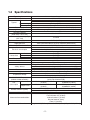
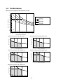
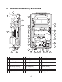
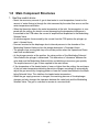
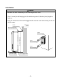
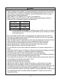
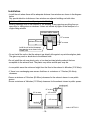
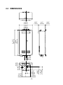
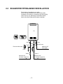
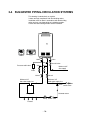
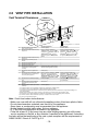
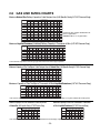
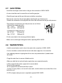
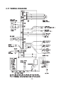
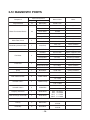
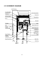
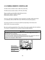
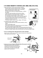
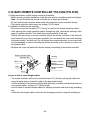
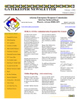
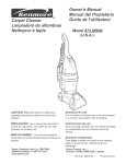
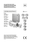
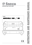
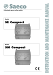
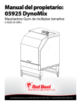
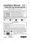
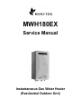
MWH180EX Service Manual Instantaneous Gas Water Heater (Residential Outdoor Unit) Table of Contents 1. General Outline of Appliance 1-1 1-2 1-3 1-4 1-5 1-6 1-7 2. Installation and Related Work 2-1 2-2 2-3 2-4 2-5 2-6 2-7 2-8 2-9 2-10 2-11 2-12 2-13 2-14 2-15 2-16 2-17 3. Features .......................................................................................................................................... 1 Specifications ................................................................................................................................. 2 Performance ................................................................................................................................... 3 General Construction (Parts Names) ............................................................................................. 4 Main Component Structures ........................................................................................................... 5 Main Safety Devices ....................................................................................................................... 9 Scale Build Up Alarm .................................................................................................................... 10 INSTALLATION INSTRUCTIONS ................................................................................................. 11 DIMENSIONS ............................................................................................................................... 16 SUGGESTED PIPING-BASIC INSTALLATION ............................................................................ 17 SUGGESTED PIPING-CIRCULATION SYSTEMS ....................................................................... 18 VENT PIPE INSTALLATION ......................................................................................................... 19 GAS LINE SIZING CHARTS ........................................................................................................ 20 GAS PIPING ................................................................................................................................. 21 WATER PIPING ............................................................................................................................ 21 PRESSURE RELIEF VALVE ........................................................................................................ 22 ELECTRICAL CONNECTION ...................................................................................................... 22 WIRING DIAGRAM ....................................................................................................................... 24 DIAGNOSTIC POINTS ................................................................................................................. 26 SCHEMATIC DIAGRAM ............................................................................................................... 27 WIRING REMOTE CONTROLLER ............................................................................................... 28 MAIN REMOTE CONTROLLER CMR-2250 (P/N 3748) .............................................................. 29 BATH REMOTE CONTROLLER YST-2250 (P/N 3749) ................................................................ 30 TESTING OPERATION ................................................................................................................ 31 Service and Maintenance 3-1 3-2 3-3 3-4 3-5 3-6 3-7 3-8 3-9 3-10 3-11 Operation Principles ..................................................................................................................... 32 Time Charts .................................................................................................................................. 33 Flow Charts .................................................................................................................................. 35 Fault Findings and Error Code ...................................................................................................... 36 Gas Setting Procedure ................................................................................................................. 39 Combustion Specification, Various Combination Setting .............................................................. 40 Remote Controllers Special Features ........................................................................................... 42 Disassembling/Assembling Parts ................................................................................................. 44 Procedure for Flushing Water Heater ........................................................................................... 53 Exploded View .............................................................................................................................. 56 Parts List ....................................................................................................................................... 57 1. General Outline of Appliance 1-1 Features 1. High-performance & high-capacity water heater features • Stable heating and supplying from 0.58 to 5.8 GPM with the proven temperature control method combining the feed forward, feedback and water flow control. • Design to reduce water temperature drops to hold temperature variation upon re-feeding • Maximum flow rate of 5.8 GPM (22 L/min) allowing simultaneous hot water supply for the kitchen and shower. 2. Environmentally-conscious and low NOx exhaust • The rich-lean design of the combustion burners allows the value of NOx to be lower than 55 ppm. 3. Self-diagnostic function • Detects the scale-clogging of the heat exchanger assembly (warning). • Detects the blocked exhaust system (alarm). 4. Improved reliability • The potted PCB (Printed Circuit Board) and connectors equipped with retainers have greatly improved the reliability of the electronic components. 5. The PCB has a function to let the LED flash upon heater trouble and the remote controller has an error-display function. 6. With ultra-low power consumption, the optional remote controllers have highly visible display (equipped with a backlight). The main remote controller and the bath remote controller are different in design. -1- 1-2 Specifications Type of appliance Model number Installation Type of Hot water supply Exhaust system Power supply Ignition system Outer panel material Hot water capacity (water temp. +25°C rise) Maximum hot water capacity (54°F rise) Maximum water supply pressure Recommended minimum water supply pressure Minimum operational water flow Electrical comsumption Gas Water inlet Hot water outlet Exhaust temperature Noise level NOx Connections Safety devices Dimensions Weight Temperrature Range Available Default Temperatures (without remote controller) Gas consumption Natural Gas Propane Gas Remote controller (option) Remote controller cable (option) Clearance from combustibles Carton box dimensions Gas continuous flow water heater MWH-180EX Outdoor only Wall hanging End stop system Forced combustion Appliance AC120V 60Hz Remote controller DC12V (digital) Direct electronic ignition Pre-Painted Galvanized Steel Sheet 0.58 ~ 5.8 GPM 5.8 GPM 150PSI (1.0MPa) 15PSI (recommended 25-75 psi for maximum performance) 0.58GPM (2.2L/min) Normal 58W Standby Main/Bath remote controller on 3.7 W Anti-frost heater operation 84W R3/4NPT R3/4NPT R3/4NPT below 480°F 49dB 55ppm Max. Flame failure - Flame rod, Over heat switch 210°F, Over heat limit 203°F Thermal fuse for heat exchanger 363°F, Over current - fuse (5A) Automatic frost protection, Combustion fan motor rpm check - PCB Height 22 5/8" (575mm) Width 13 25/32" (350mm) Depth 6 1/2" (165mm) 40lbs. (18kg) Main remote controller 96 - 140°F Bath remote controller 96 - 140°F 110°F, 120°F, 140°F, 165°F (set by Dip switch on PCB) Maximum 180,000Btu/h Minimum (reference) (52.8kW) 20,000Btu/h (6.0kW) Maximum 180,000Btu/h Minimum (reference) (52.8kW) 20,000Btu/h (6.0kW) CMR-2250 (P/N3748) Main control kitchen / laundry YST-2250 (P/N3749) Bathroom control Nonpolarized two core cable Top of heater 12" (30.5cm) Front of heater 24" (61.0cm) Sides of heater 6" (15.2cm) Back of heater 0" (0cm) Floor 12" (30.5cm) Height 30 1/8" (765mm) Width 15 15/16" (405mm) Depth 9 5/8" (245mm) -2- 1-3 Performance Performance-Capacity characteristic curves 8.0 7.0 Water flow rate [GPM] 6.0 Inlet water temperature 41°F (5°C) 50°F (10°C) 59°F (15°C) 68°F (20°C) 77°F (25°C) 6.3 GPM 5.8 5.0 4.0 3.0 2.0 1.0 0.5 0.58 GPM 96 95 100 110 120 130 140 150 160 165 Hot water temperature [°F] With water temperature 50°F (10°C) at inlet 8.0 8.0 7.0 7.0 Water flow rate [GPM] Water flow rate [GPM] With water temperature 41°F (5°C) at inlet 6.0 5.0 4.0 3.0 2.0 1.0 0.5 110 120 130 140 Hot water temperature [°F] 150 2.0 Water flow rate [GPM] 4.0 3.0 2.0 6.0 150 160 165 110 120 130 140 Hot water temperature [°F] 150 160 165 3.0 2.0 7.0 5.8GPM 5.0 4.0 3.0 2.0 0.58 GPM 110 120 130 140 Hot water temperature [°F] 150 0.58 GPM 96 95 100 8.0 96 95 100 5.8GPM 4.0 With water temperature 77°F (25°C) at inlet Water flow rate [GPM] 120 130 140 Hot water temperature [°F] 5.0 1.0 0.5 0.58 GPM 96 95 100 1.0 0.5 110 7.0 5.8GPM 5.0 6.0 0.58 GPM 8.0 7.0 Water flow rate [GPM] 3.0 With water temperature 68°F (20°C) at inlet 8.0 1.0 0.5 4.0 96 95 100 160 165 With water temperature 59°F (15°C) at inlet 6.0 5.8GPM 5.0 1.0 0.5 0.58 GPM 96 95 100 6.0 160 165 -3- 110 120 130 140 Hot water temperature [°F] 150 160 165 1-4 General Construction (Parts Names) 4 2 22 16 3 1 19 18 28 27 24 25 29 8 7 23 20 15 14 26 30 6 21 10 21 17 10 12 13 9 11 5 No. Description Description No. Description 21 Junction Box Front Panel 11 Water Filter Assembly 22 Heat Exchanger Thermistor Casing Assembly 12 Drain Plug 23 Manifold Assembly Heat Exchanger 13 Water Flow Sensor 24 Flame Rod Exhaust Chamber Assembly 14 Surge Protector 15 Water Flow Contorol Device 25 Electrode Gas Connection Frost Sencing Switch Modulation Valve Unit Over Heat Switch 26 6 16 (bi-metal switch) (Gas Control Assembly) (bi-metal switch) Outgoing Thermistor Combustion Fan Motor Assembly 27 Burner Assembly 7 17 28 Combustion Chamber Assembly 8 Transformer(100V) 18 Igniter Transformer 29 Fuse(3.15A) 9 Water Inlet 19 Thermal Fuse Device 30 Fuse(5A) 10 Hot Water Outlet 20 PCB Unit No. 1 2 3 4 5 -4- 1-5 Main Component Structures 1. Gas flow control device • Feeds the necessary amount of gas to heat water to a set temperature, based on the amount of water flowing in through the inlet measured by the water flow sensor and the water temperature calculation. • When the thermistor detects the water temperature at the inlet, the temperature is compared with the setting. An electric current representing the temperature difference is transmitted to the PCB where the current is amplified and dispatched to the Modulating Solenoid Valve. • An electromagnetic force caused by the current from the PCB pushes the plunger upward. <Upward force> • Pressure received at the diaphragm due to internal pressure in the chamber of the Modulating Solenoid Valve pushes the plunger downward. <Downward force> • The plunger stops moving and stays at a certain position when the Upward and Downward force are balanced. • As the plunger remains at the position, the valve position of the Modulating Solenoid Valve linked to the plunger is determined. This determines a "clearance" between the valve body and the Modulating Solenoid Valve, establishing a necessary gas quantity. The required amount of gas is then supplied to the main burner. • If the temperature of the heated water is lower or higher than the setting, the resistance of the hot water temperature detecting thermistor changes accordingly to automatically adjust the gas amount by changing greater or lower the current transmitted to the Modulating Solenoid Valve. This stabilizes the heated water temperature. • When the gas supply pressure is changed, the receiving pressure of the diaphragm changes and also changes the clearance between the valve body and the Modulating Solenoid Valve. The gas is controlled to remain at a constant level. -5- 82 21 21 OUT1 10 20 OUT 2 Diaphragm 96.5 LP 13A 127.7 Coil Plunger UP34-33C 13A Plunger spring Pressure check hole Solenoid Valve Modulating Solenoid Valve Filter IN -6- 2. Water flow sensor * Measures the water flow as its rotor (bladed wheel) spins with the passing water. The rotation of the rotor is detected by the sensor rotor (blade equipped with a magnet) of the wheel and the Hall element which calculates the water quantity. ø30 Sealant Hall element IC 50 150 ° 20 Main body Rotor ø30 Inlet 3. Water flow control device 50 29.5 35 Wa t e r f l ow c o n t r o l d ev i c e m o t o r Va l ve b o d y Va l ve m a i n b o d y 28.5 * When water flows more than water heater capacity, hot water temperature becomes lower than the setting. The water flow control device automatically reduces the water flow to prevent such temperature drops. If the water flow is greater than the heater capacity, a signal from the PCB activates the water flow control device's motor (stepping motor). In response to this operation, the valve body of the water flow control device also is operated to reduce the water flow by narrowing the water path. Water flow fluctuations are detected and transmitted to the PCB by the water flow sensor. When the appropriate level of water flow is achieved, the PCB signals the motor to stop. Thus, the water flow remains at this level. ø30 -7- 4. Combustion control of rich and lean burners 1) Ignition start After the Main Gas Solenoid Valve, Gas Solenoid Valve 1, Gas Solenoid Valve 2 open respectively as required, the Gas Modulating Solenoid Valve, being held at the slow ignition position (with gas supply at a constant rate), operates to ignite rich burners and lean burners. 2) During combustion When a heating capacity higher than a certain level (approximately 95,000 BTU) is required, both Gas Solenoid Valve 1 and Gas Solenoid Valve 2 are opened to burn with rich and lean burners while the gas supply is controlled by the Gas Solenoid Valve. When the required heating capacity becomes lower than a certain level (approximately 110,000 BTU), the Gas Solenoid Valve 2 is closed while Gas Solenoid Valve 1 remains open to combust with 12 rich burners, with the gas supply controlled by the Gas Modulating Solenoid Valve. Electrode Flame rod Main burner Gas Solenoid Valve 2 Combustion fan Gas Solenoid Valve 1 Gas Modulating Solenoid Valve Main Gas Solenoid Valve Gas -8- 1-6 Main Safety Devices 1. Water flow sensor (Boil-dry protection) When the water flow sensor detects the flow rate set for starting ignition (ignition water flow) or higher, the water heater starts operation. Ignition water flow: 0.71 GPM (2.7 L/min.) Extinction water flow: 0.58 GPM (2.2 L/min.) 2. Flame rod (Flame failure detection) Electric signals are transmitted to the flame detection circuit to confirm the normal combustion when the flame rod detects the rectification of normal combustion flame. Therefore, if the combustion of the burners is not normal, the signals are not sent via the flame rod. The gas control assemblies are closed without the signals and the error code "111" or "121" is displayed on the remote controllers. (Normal with 0.8 A or higher) 3. Thermal fuse (Over-temperature protection system) The thermal fuse is placed around the heat exchanger assembly. If the ambient temperature inside the water heater becomes extremely high, the fuse will melt down to break the power circuit. In such a case, as no power is supplied to the gas control assemblies, the gas supply is stopped and the combustion is stopped. (The system is activated to blow the fuse at 363F [184C].) 4. Over heat switch (residual) Even if the heat exchanger assembly is over heated by no-water combustion, every gas path is closed to avoid risks. At this time, the error code "141" is displayed on the remote controllers. (The switch is provided with a auto-restoration function and turns OFF at 212F [100C].) 5. Fan revolution detection device (Hall IC) The device detects the fan revolution speed to control the air supply necessary for normal combustion. If the fan revolution is out of the preset standard range, the gas control assemblies are closed to stop the combustion before combustion failure occurs. In this case, the error code "611" is displayed on the remote controllers. 6. Anti-freeze system (Frost sensing switch and heater) To prevent freezing in the hot water supply circuit, anti-frost heaters are provided at major points of water flow paths in the unit. The heaters are activated by the thermistors in the unit. The 4 heaters, one located on the front side of heat exchanger is 48W, the water supply pipe is 16W, the connection of water inlet is 10W and the connection of hot water outlet is 10W. In order to keep the heat is the most vulnerable part of heat exchanger, the big capacity 48W heater is mounted. (The system turns ON at 37F [3C] and OFF at 55F [13C].) -9- 1-7 Scale Build Up Alarm Summary The temperature of residual hot water becoms higher as scale starts to build up inside the heat exchanger. The extent of scale build up is judged by monitoring the temperature of residual hot water. “LC”, scale build up alarm, is indicated on the remote controller. Flow chart (See page 35) 1) The set temperature by remote controller needs to be 120F and over to activate the alarm. 2) The stability of the temperature of outgoing hot water is detected by the thermistor of the can body. 3) The temperature of residual hot water is detected by the thermistor of the can body when hot water flow is stopped. The criterion for judging scale build up varies depending on combustion capacity. 4) “LC” alarm and set temperature are indicated alternately on the remote controller. Alarm specification * Hot water supply is available even if “LC” is indicated on the remote controller. * ”LC” alarm can be reset by turning the power switch off and on. * No detection is possible in case remote controller is disconnected. * ”LC” alarm is not memorized in the alarm history record. Conditions for invalid detection * The thermistor of the can body is broken or short-circuited. * The alarm is in process. * During forced combustion by the dip switch. * The set temperature is under 120F. - 10 - 2. Installation and Related Work 2-1 INSTALLATION INSTRUCTIONS • The cases shown below are classified by the degree of risk and damage. Be sure to follow the instruction for your safety. Danger "Danger" indicates that serious injuries or even death may result from the improper installation due to negligence of following the instructions. Warning "Warning" indicates the possibility that serious injuries or even death may result from the improper installation due to negligence of following the instructions. Caution "Caution" indicates the possibility that some injuries or material damage may result from the improper installation due to negligence of following the instructions. Each mark indicates: General prohibited Never fail to do. Ground Danger Never install the unit indoors as it is exclusively for outdoor use. Do not install it in the bathroom. Electric shock or leakage may result. To the installers. Warning • Read and understand the installation manual to carry out the installation as specified for proper and safe usage. • A competent dealer or plumber should perform the complete installation, including placement, plumbing, gas line, and electrical connection. Consumers should not try to install their own unit. • Make double sure that the unit runs in accordance with the check items of "trial run" standard after it is installed. (refer to Testing operation) • When installation of water heater, be sure to wear protective equipment to prevent injuries and burns. After installation, do not enclose the unit with anything such as corrugated sheets, which may develop an indoor-like closed environment. It poses serious danger due to the shortage of oxygen or imperfect combustion. • If the supply water pipe is incorrectly connected to the gas inlet, do not attempt to operate the unit by simply reconnecting the pipe correctly, this will only cause further damage to the unit. Corrective measures • It will be necessary to replace all the internal gas components if the gas piping is hooked up incorrectly. - 11 - Before installation. Verification of the unit. Warning • Make sure the unit to be installed suits the intended use and application. • Do not use any gas other than specified on the sticker. • Do not operate with any power source (voltage/frequency) other than specified on the sticker. DIRECT VENT AUTOMATIC INSTANTANEOUS GAS WATER HEATER FOR INDOOR INSTALLATION NATURAL GAS / PROPANE GAS ANSI Z21.10.3-2004 CSA 4.3-2004 CHAUFFE-EAU INSTANTAN AUTOMATIQUE ¸ VENT DIRECT POUR INSTALLATION INT RIEUR. NAT / GPL MODEL : MWH180EX NATURAL GAS (Gaz Naturel) MAX. INPUT Debit calorifique max. PROPANE GAS (GPL) 180,000 Btu/h MIN. INPUT Debit calorifique min. NATURAL GAS REFER TO THE LOCAL GAS AUTHORITY FOR CONFIRMATION ON THE GAS TYPE, IF IN DOUBT. DO NOT REMOVE THIS LABEL UNTIL THE APPLIANCE HAS BEEN INSTALLED AND TESTED Si vous ne savez pas le type de gaz, contactez le fournisseur de gaz ou les autorit locaux. Enlevez pas cette etiquette jusqu« l«appareil a t installer et verifie. 180,000 Btu/h 20,000 Btu/h 20,000 Btu/h GAS PRESSURE INLET MAX. Pression de gaz entr e max. 10.5 inches W.C. 10.5 pounces W.C. 14.0 inches W.C. 14.0 pounces W.C. GAS PRESSURE INLET MIN. Pression de gaz entr e min. 4.0 inches W.C. 4.0 pounces W.C. 8.0 inches W.C. 8.0 pounces W.C. GAS PRESSURE MANIFOLD MAX. Pression d«admission max. 2.75 inches W.C. (2.55) 2.75 pounces W.C. (2.55) 3.10 inches W.C. (2.75) 3.10 pounces W.C. (2.75) GAS PRESSURE MANIFOLD MIN. Pression d«admission min. 0.4 inches W.C. 0.4 pounces W.C. 0.4 inches W.C. 0.4 pounces W.C. SERIAL NUMBER Manufactured for: MONITOR PRODUCTS INC. For the safety and the proper usage. Read and understand "IMPORTANT ISSUES TO BE NOTED IN PARTICULAR" before the use. The cases shown below are classified by the degree of risk and damage. Be sure to follow the instruction for your safety. AC 120V — 60Hz MAX. WATER PRESSURE Pression d eau max. 150 PSI ¥ Attention au fuite de gaz. (Peut r sulter en feu) ¥ Ne jamais installer le chauffe-eau a l interieure car il est exclusivement pour usage a l ext rieur. ¥ Ne pas installer dans la sale de bain. (choc lectrique ou une fuite de l eau peut resulter) Avertissement Warning Minimum clearances from combustible of non-combustible construction D gagements minimaux assurer entre les parois de l«appareil et les constuctions combustibles ou incombustibles 0 po arri re 24 po devant d«appareil 12 po dessus 6 po c t s 20511040 Danger ¥ Watch for gas leak (May cause fire.) ¥ Never install the unit indoors as it is exclusively for the outdoor use. ¥ Do not install it in the bathroom. Electric shock or leakage may result. Wiring Diagram inside Front Cover Sch ma du c blage derri re le couvercle avant. Ref.: New Jersey L instruction securit pour l usage de MWH180. Lisez et comprendrez Instructions de securit avant utilisation avant usage. Les situations suivant sont cat goris par le degr de risque et danger. Suivez les instructions exactement pour votre securit . Danger ELECTRICAL RATING Regime nominal lectrique Back: 0 inch Front:24 inches Top: 12 inches Side: 6 inches ONLY FOR USE WITH ¥ Caution to prevent scalding. ¥ Confirm type of gas and power supply. ¥ Pay attention to children. (Cause of accident.) ¥ No disassembly, repair or modification. (May cause fire, electric shock or other accidents.) ¥ Caution for flammable items. ¥ Do not touch water heater during or immediately after operation. ¥ Do not use any gas other than specified on the sticker. FOR YOUR SAFETY Do not store or use gasoline or other flammable vapors and liquids in the vicinity of this or any other appliance. This water heater is required to have with a pressure relief valve. For safe operation of the water heater the relief valve must not be removed from its designated point of installation or plugged. POUR VOTRE SÉCURITÉ Ne pas entreposer ne utiliser d«essence ne d«autres vapeurs ou liquides inflammables proximit de cet appareil ou de tout autre appareil. Ce chauffe-eau d it tre installer avec un soupape de d charge. Pour assurer le fonctionnement s curitaire du chauffe-eau, ne pas retirer ni obturer cette soupape de d charge. ¥ Attention a pr venier des br lures. ¥ Confirmez le type de gaz et la puissance lectrique. ¥ Payez attention aux enfants. (pr venir des br lures) ¥ Pas de d montage, r paration ou modification. ( tre cause du feu, choc lectrique ou d outre accidents) ¥ Ne pas place des mat riaux combustible pr s du chauffe-eau. ¥ Ne touchez pas le chauffe-eau pendant op ration ou juste apr s terminer l op ration. ¥ N employez aucun gaz autre que sp cifique sur l tiquette. MWH180EX 20511090 or DIRECT VENT AUTOMATIC INSTANTANEOUS GAS WATER HEATER FOR INDOOR INSTALLATION NATURAL GAS / PROPANE GAS ANSI Z21.10.3-2004 CSA 4.3-2004 CHAUFFE-EAU INSTANTAN AUTOMATIQUE ¸ VENT DIRECT POUR INSTALLATION INT RIEUR. NAT / GPL MODEL : MWH180EX NATURAL GAS (Gaz Naturel) MAX. INPUT Debit calorifique max. PROPANE GAS (GPL) 180,000 Btu/h MIN. INPUT Debit calorifique min. PROPANE GAS REFER TO THE LOCAL GAS AUTHORITY FOR CONFIRMATION ON THE GAS TYPE, IF IN DOUBT. DO NOT REMOVE THIS LABEL UNTIL THE APPLIANCE HAS BEEN INSTALLED AND TESTED Si vous ne savez pas le type de gaz, contactez le fournisseur de gaz ou les autorit locaux. Enlevez pas cette etiquette jusqu« l«appareil a t installer et verifie. 180,000 Btu/h 20,000 Btu/h 20,000 Btu/h GAS PRESSURE INLET MAX. Pression de gaz entr e max. 10.5 inches W.C. 10.5 pounces W.C. 14.0 inches W.C. 14.0 pounces W.C. GAS PRESSURE INLET MIN. Pression de gaz entr e min. 4.0 inches W.C. 4.0 pounces W.C. 8.0 inches W.C. 8.0 pounces W.C. GAS PRESSURE MANIFOLD MAX. Pression d«admission max. 2.75 inches W.C. (2.55) 2.75 pounces W.C. (2.55) 3.10 inches W.C. (2.75) 3.10 pounces W.C. (2.75) GAS PRESSURE MANIFOLD MIN. Pression d«admission min. 0.4 inches W.C. 0.4 pounces W.C. 0.4 inches W.C. 0.4 pounces W.C. SERIAL NUMBER Manufactured for: MONITOR PRODUCTS INC. For the safety and the proper usage. Read and understand "IMPORTANT ISSUES TO BE NOTED IN PARTICULAR" before the use. The cases shown below are classified by the degree of risk and damage. Be sure to follow the instruction for your safety. Danger ELECTRICAL RATING Regime nominal lectrique AC 120V — 60Hz MAX. WATER PRESSURE Pression d eau max. 150 PSI Wiring Diagram inside Front Cover Sch ma du c blage derri re le couvercle avant. Minimum clearances from combustible of non-combustible construction D gagements minimaux assurer entre les parois de l«appareil et les constuctions combustibles ou incombustibles Back: 0 inch Front:24 inches Top: 12 inches Side: 6 inches ONLY FOR USE WITH 0 po arri re 24 po devant d«appareil 12 po dessus 6 po c t s FOR YOUR SAFETY Do not store or use gasoline or other flammable vapors and liquids in the vicinity of this or any other appliance. This water heater is required to have with a pressure relief valve. For safe operation of the water heater the relief valve must not be removed from its designated point of installation or plugged. POUR VOTRE SÉCURITÉ Ne pas entreposer ne utiliser d«essence ne d«autres vapeurs ou liquides inflammables proximit de cet appareil ou de tout autre appareil. Ce chauffe-eau d it tre installer avec un soupape de d charge. Pour assurer le fonctionnement s curitaire du chauffe-eau, ne pas retirer ni obturer cette soupape de d charge. ¥ Watch for gas leak (May cause fire.) ¥ Never install the unit indoors as it is exclusively for the outdoor use. ¥ Do not install it in the bathroom. Electric shock or leakage may result. Warning ¥ Caution to prevent scalding. ¥ Confirm type of gas and power supply. ¥ Pay attention to children. (Cause of accident.) ¥ No disassembly, repair or modification. (May cause fire, electric shock or other accidents.) ¥ Caution for flammable items. ¥ Do not touch water heater during or immediately after operation. ¥ Do not use any gas other than specified on the sticker. Ref.: New Jersey 20511040 L instruction securit pour l usage de MWH180. Lisez et comprendrez Instructions de securit avant utilisation avant usage. Les situations suivant sont cat goris par le degr de risque et danger. Suivez les instructions exactement pour votre securit . Danger ¥ Attention au fuite de gaz. (Peut r sulter en feu) ¥ Ne jamais installer le chauffe-eau a l interieure car il est exclusivement pour usage a l ext rieur. ¥ Ne pas installer dans la sale de bain. (choc lectrique ou une fuite de l eau peut resulter) Avertissement ¥ Attention a pr venier des br lures. ¥ Confirmez le type de gaz et la puissance lectrique. ¥ Payez attention aux enfants. (pr venir des br lures) ¥ Pas de d montage, r paration ou modification. ( tre cause du feu, choc lectrique ou d outre accidents) ¥ Ne pas place des mat riaux combustible pr s du chauffe-eau. ¥ Ne touchez pas le chauffe-eau pendant op ration ou juste apr s terminer l op ration. ¥ N employez aucun gaz autre que sp cifique sur l tiquette. MWH180EX 20524910 Location of the unit. Decide where to install the unit by considering customer’s request and clearances. Warning Ventilation • Install the unit where there is enough space for ventilation. • Do not install the unit where flammables such as gasoline, benzene, and adhesive are handled. • This unit does not allow the use of extended exhaust pipes. • Install the unit as far as possible, away from anything in front or above even if it is noncombustible in order to prevent exhaust gas recirculation, and staining of surfaces. • Take preventive measures against snow drifts for air inlet and exhaust outlet to stay unaffected in case there is a possibility that they may be blocked by snow fall. - 12 - Installation. Caution • Reinforce the wall if necessary as this unit weighs about 40lbs. 1. Twist 1 screw (for wall hanging) into the wall leaving about 1/8inches (4mm) length to hook on. 2. Hook the center hole of the wall hanging bracket onto the screw and securely fix the unit with 4 screws. Screw (for wall hanging) About 1/8" (4mm) Wall hanging bracket 23 1/32" (585mm) Screw (for wall hanging) Screw (for wall hanging) Screw (for wall hanging) Screw (for wall hanging) Wall hanging bracket - 13 - Caution • Check if adjacent wall or ceiling is fire resistant and allows safe distance for fire prevention. • This water heater is suitable for residential water (potable) heating only. Do not use this water heater for space heating, combination space heating/domestic water heating, or commercial water heating applications. • MWH-180EX is not suitable for use in pool or spa applications. • Maintain proper space around the unit for proper servicing and operation. Minimum clearances from combustible materials are listed below. Top of heater Front of heater Sides of heater Back of heater Floor 12" 24" 6" 0" 12" (30.5cm) (61.0cm) (15.2cm) (0cm) (30.5cm) Note : These clearances do not apply if installing unit into an MPI recess box, however they do apply from the exhaust port to combustible once the exhaust port comes out of the recess box. • Do not install MWH-180EX under an overhang less than 3feet from the top of the unit. When the overhang protrudes out over MWH-180EX greater than 3feet, the area under the overhang must be open on 3sides. • When the water heater is installed within a recess box, the clearances from the top, bottom, sides, and back surfaces of the recess box to combustible materials are 0inch. The clearance from combustibles from the front of the recess box is 24inches. • Secure enough space so that the inspection and repairs can be done easily. • Secure space not only in front but also under the unit. • Do not install the unit over other combustion appliances such as gas cooking stove or a range. Oil residue and dust in the air can adhere to the burner and the heat exchanger resulting in deformation, loss of efficiency, or damage to electronic components. • Do not install the exhaust outlet near the outlets of the other appliances. Install the air inlets away from the wind path as the wind may cause imperfect combustion. • Do not install the unit where commercial chemicals are used. Those chemicals are ammonia, sulfur, chloride, ethylene compound and acids which are used at beauty shop, laundry, factory and so forth. • Do not install the unit over food or dishes. • Installer must install a Pressure relief valve. Pipe pressure relief to a drain or outside environment, or within 4inches of the floor. Pipe pressure relief discharge to a drain or outside environment. (refer to page 22) • The appliance should be located in an area where leakage from the unit or connections will not result in damage to the area adjacent to the appliance or to lower floors of the structure. When such locations can not be avoided, it is recommended that a suitable drain pan, adequately drained, be installed under the appliance. The pan must not restrict combustion airflow. - 14 - Installation. • Install the unit where there will be adequate distance from windows as shown in the diagram below. Pay special attention to distances from windows on adjacent buildings on both sides. Definition of Clearances from Openings in the Building Building openings refer to the windows of the building, or any openings resulting from an open door or sliding doors or windows. It does not include sky lights or the fixed part of a single sliding window. windows above heater 6" or more 6" or more windows to the side 12" or more 6" or more Install the unit so that clearances from opening are as shown in the shaded area. • Do not install the unit so that the exhaust gas directly hits against any reinforced glass plate. The glass may crack or break due to the exhaust heat. •Do not install the unit near plants, pets, or low heat resistant plastic products that are susceptible to the exhaust heat. The plants may wither and the pets may die. • In non-public areas the minimum height from the floor to the exhaust is 84inches (213.36cm). • If there is an overhanging eave ensure that there is a minimum of 12inches (30.48cm) clearance. •Ensure a minimum of 24inches (60.96cm) clearance for the exhaust stream in non-public spaces. Ensure a minimum of 48inches(121.92cm) clearance for the exhaust stream in public spaces. hanging wall 12" or less 24" or more 48" or more 84" or more handrail the private balcony the public space - 15 - *code is NFPA 211 2-2 DIMENSIONS 13 25/32" (350mm) 15/32" (12mm) 6 1/2" (165mm) 22 5/8" (575mm) 1 31/32" (50mm) 3 13/16" (97mm) 4 15/32" (113.5mm) - 16 - 2 25/32" (71mm) 1 5/16" (33.5mm) 3 9/16" (97mm) 2 3/8" (60mm) 23 1/32" (585mm) 3 15/16" (100mm) 19/32" (15mm) 2-3 SUGGESTED PIPING-BASIC INSTALLATION This drawing is intended only as a guide. It does not imply compliance with local building codes. Installation must be done in accordance with local building codes and may vary depending on installation location. Confer with local building officials before installation. Union Union Union Shut off valve Valve 1 Valve 2 Pressure relief valve Minimum 3/4" Gas supply Drain Valve 3 Valve 4 Minimum 3/4" Hot water supply line Minimum 3/4" Cold water supply line - 17 - 2-4 SUGGESTED PIPING-CIRCULATION SYSTEMS This drawing is intended only as a guide. It does not imply compliance with local building codes. Installation must be done in accordance with local building codes and may vary depending on installation location. Confer with local building officials before installation. Union Union Union Shut off valve Valve 1 Valve 2 Pressure relief valve Minimum 3/4" Gas supply Drain Valve 3 Valve 4 Minimum 3/4" Hot water supply line Minimum 3/4" Cold water supply line Union Check valve Hot water return Storage tank Pump Check valve Fixtures - 18 - 2-5 VENT PIPE INSTALLATION Vent Terminal Clearances. INSIDE CORNER DETAIL. G v H A D v B E L B C B D FIXEED CLOS v v LE OPERAB F v D FIXEED S ABLE CLO OPER v B I x v B v x v K J A B M v x VENT TERMINAL. AIR SUPPLY INLET. AREA WHERE TERMINAL IS NOT PERMITTED. A= B= C= D= E= F= G= H= I = J = K= L= M= Clearance above grade, veranda, porch, deck, or balcony. Clearance to window or door that may be opened. Clearance to window or door that may be opened. Clearance to permanently closed window. Clearance to unventilated soffit. Clearance to outside corner. Clearance to inside corner. Clearance to each side of center line extended above meter/regulator assembly. Clearance to service regulator vent outlet. Clearance to nonmechanical air supply inlet to building or the combustion air inlet to any other appliance. Clearance to a mechanical air supply inlet. Clearance above paved sidewalk or paved driveway located on public property. Clearance under veranda, porch deck, or balcony. Canadian Installations 12 inches (30cm) 1 US Installations 2 12 inches (30cm) 6 inches (15cm) for appliances 10,000 Btuh (3kW), 12 inches (30cm) for appliances 10,000 Btuh (3kW) and 100,000 Btuh (30kW), 36 inches (91cm) for appliances 100,000 Btuh (30kW) * 6 inches (15cm) for appliances 10,000 Btuh (3kW), 9 inches (23cm) for appliances 10,000 Btuh (3kW) and 50,000 Btuh (15kW), 12 inches (30cm) for appliances 50,000 Btuh (15kW) * * * * * 3 feet (91cm) within a height 15 feet above the meter/regulator assembly. * * * * 3 feet (1.83m) * 6 inches (15cm) for appliances 10,000 Btuh (3kW), 12 inches (30cm) for appliances 10,000 Btuh (3kW) and 100,000 Btuh (30kW), 36 inches (91cm) for appliances 100,000 Btuh (30kW) 6 feet (1.83m) 7feet (2.13m) 3 6 inches (15cm) for appliances 10,000 Btuh (3kW), 9 inches (23cm) for appliances 10,000 Btuh (3kW) and 50,000 Btuh (15kW) 12 inches (30cm) for appliances 50,000 Btuh (15kW) 3 feet (91cm) above if within 10 feet (3m) horizontally. * 12 inches (30cm) 4 * * 1 In accordance with the current CSA B149.1 Natural Gas and Propane Installation Code. In accordance with the current ANSI Z223.1 / NFPA 54 National Fuel Gas Code. A vent shall not terminate directly above a sidewalk or paved driveway that is located brtween two single family dwellings and serves both dwellings. 4 Permitted only if veranda, porch, deck, or balcony is fully open on a minimum of two sides beneath the floor. * For clearances not specified in ANSI Z223.1 / NFPA 54 or CSA-B149.1, one of the following shall be indicated : a) A minimum clearance value determined by testing in accordance with section 2.20, or ; b) A reference to the following footnote : 2 3 Note : Check local codes and ordinances. • Make sure snow drift will not suffocate the appliance when it has been piled or fallen. • Do not place hazardous materials near the end of the appliance. • Some vapor or condensation may be generated from the appliance. • Not be located in public traffic areas, such as walkways. • 6' (1.8m) from the combustion air intake of any appliance. • Place the at least 3' (0.9m) away from any other building opening, gas utility meter, service regulator or the like, or less distance if specified in the appliance's instructions. And also ensure that positioning of the vent system complies with the requirements of AS5601/AG601 Clause 5.13.6.2/Fig. 5.3 - 19 - 2-6 GAS LINE SIZING CHARTS Maximum Natural Gas Delivery Capacity in Cubic Feet per Hour (0.60 Specific Gravity, 0.5" WC Pressure Drop) Length in Feet PipeSize 10' 20' 30' 40' 100' 125' 1/2" 174 119 96 82 50' 73 60' 66 70' 61 80' 56 90' 53 50 44 3/4" 363 249 200 171 152 138 127 118 111 104 93 1" 684 470 377 323 286 259 239 222 208 197 17 4 1 1/4" 1404 965 775 663 588 532 490 456 428 404 35 8 1 1/2" 2103 1445 1161 993 880 798 734 683 641 605 536 2" 4050 2784 2235 1913 1696 1536 1413 1315 1234 1165 1033 2 1/2" 6455 4437 3563 3049 2703 2449 2253 2096 1966 1857 1646 3" 11,412 7843 6299 5391 4778 4329 3983 3705 3476 3284 2910 3 1/2" 16,709 11,484 9222 7893 6995 6338 5831 5425 5090 4808 4261 Contact the Gas Supplier for Btu/Cubic Ft. of the Supplied Gas. 1000 Btu/Cubic Ft. is a Typical Value. 4" 23,277 15,998 12,847 10,995 9745 8830 8123 7557 7091 6698 5936 Maximum Liquified Petroleum (Undiluted) Delivery Capacity in Thousands of Btuh (0.5" WC Pressure Drop) Length in Feet PipeSize 10' 20' 30' 40' 50' 60' 100' 125' 150' 1/2" 275 189 152 129 114 103 70' 96 80' 89 90' 83 78 69 63 200' 55 3/4" 567 393 315 26 7 237 217 196 185 173 162 146 132 112 1" 1071 732 590 504 44 8 409 378 346 322 307 275 252 213 1 1/4" 2205 1496 1212 1039 913 834 771 724 677 630 567 511 440 1 1/2" 3307 2299 1858 1559 1417 1275 1181 1086 1023 976 866 787 675 2" 6221 4331 3465 2992 2646 2394 2205 2047 1921 1811 1606 1496 1260 ** For reference only. Please consult gas pipe manufacturer for actual pipe capacities. Maximum Capacity of Flex TracPipe in Cubic Feet per Hour of Natural Gas (0.60 Specific Gravity, 0.5" WC Pressure Drop) PipeSize Length in Feet 10' 20' 30' 40' 50' 100' 150' 3/4" 206 147 121 105 94 60' 86 70' 80 80' 75 90' 71 67 55 200' 48 1" 383 269 218 188 168 153 141 132 125 118 94 82 1 1/4" 614 418 334 284 251 227 209 194 181 171 137 116 1 1/2" 1261 888 723 625 559 509 471 440 415 393 320 277 2" 2934 2078 1698 1472 1317 1203 1114 1042 983 933 762 661 Maximum Capacity of Flex TracPipe in Thousands of Btuh Liquified Petroleum (0.5" WC Pressure Drop) PipeSize Length in Feet 10' 20' 30' 40' 50' 60 ' 70' 80' 90' 100' 150' 3/4" 325 232 191 166 149 136 126 118 112 106 87 200' 76 1" 605 425 344 297 265 241 222 208 197 186 143 129 1 1/4" 971 661 528 449 397 359 330 307 286 270 217 183 1 1/2" 1993 1404 1143 988 884 805 745 696 656 621 506 438 2" 4638 3285 2684 2327 2082 1902 1761 1647 1554 1475 1205 1045 ** For reference only. Please consult gas pipe manufacturer for actual pipe capacities. TracPipe is a registered trademark of Omega Flex. Maximum Capacity of Gas Flex Connectors in Cubic Feet per Hour of Natural Gas (0.60 Specific Gravity, 0.5" WC Pressure Drop) PipeSize Length in Inches 12" 24" 36" 48" 1/2" 180 150 125 106 93 86 3/4" - 290 255 215 197 1" - 581 512 442 - 1470 1200 1130 1 1/4" Maximum Capacity of Gas Flex Connectors in Thousands of Btuh Liquified Petroleum (0.5" WC Pressure Drop) 60" PipeSize 72" Length in Inches 12" 24" 36" 48" 60" 72" 1/2" 288 240 200 169 149 137 173 3/4" - 465 409 344 315 278 397 347 1" - 930 825 708 638 556 960 930 1 1/4" ** For reference only. Please consult gas pipe manufacturer for actual pipe capacities. - 20 - - 2352 1920 1808 1536 1488 2-7 GAS PIPING • Install the manual gas control valve in the gas inlet connection of MWH-180EX. • A union should be used to connect the unit and the gas pipe. • Check the gas type and the gas inlet pressure before connecting. • Remove the screw from the test plug before checking the gas inlet pressure. Connect the manometer to the plug with the silicon tube and measure the gas inlet pressure. • The maximum and minimum gas inlet pressures are as follows. < Natural Gas supply pressure > Min. 4" W.C. (102mmH2O) Max. 10.5" W.C. (267mmH2O) < Propane Gas supply pressure > Min. 8" W.C. (203mmH2O) Max. 14" W.C. (356mmH2O) • Put the screw back in the test plug and fasten tightly. • Make sure to conduct gas leakage test before operating MWH-180EX. 2-8 WATER PIPING • Install a manual water control valve in the water inlet connection of MWH-180EX. • A union should be used on both the hot and cold water supply lines for connection. • Use soldering materials or piping that will not cause any deterioration of potable water. NO LEAD! • Purge the water lines to remove all debris and air. • Make sure both the hot and cold water supply lines are connected correctly. • A filter is placed at the water supply inlet to remove debris. Clean the filter regularly. Do not operate the unit without the filter in place. In areas of heavy debris, such as with some wells, install a whole house water filter in line before the unit. • 15 PSI or higher water pressure is required to operate MHW-180EX. - 21 - 2-9 PRESSURE RELIEF VALVE • Install an approved pressure relief valve with every gas water heater installation. • The pressure relief valve shall conform to the following requirements. Relief Valves and Automatic Gas Shutoff Devices for Hot Water Supply Systems ANSI Z21, 22. This pressure relief valve shall activate with the pressure of 150PSI. • The pressure relief valve shall be installed in the outgoing hot water supply line according to the manufacturer's instruction. • No valves or shut off device shall be placed between the relief valve and the unit. The discharge from the pressure relief valve shall be piped to the ground or into the drain system to prevent possible burns to humans or animals. Hot water discharged from the relief valve may cause severe scalding instantly and even death. • Do not cap the relief valve and do not install any depressurizer or restriction device in the relief line. • Manually operate the pressure relief valve at least once a year to check if it functions properly. 2-10 ELECTRICAL CONNECTION Warning MWH-180EX must be electrically grounded in accordance with local codes or in the absence of local codes with the most recent edition of the National Electrical Code, ANSI/NFPA 70. In Canada, all electrical wiring to the MWH-180EX should be in accordance with local codes and the Canadian Electrical Codes, CSA C22.1 Part 1. Do not rely on the gas or water piping to ground the metal parts of the water heater. Caution • Label all wires prior to disconnection when servicing controls. Wiring errors can cause improper and dangerous operation. Verify proper operation after servicing. Field wiring to be performed at time of appliance installation. • Completely turn off the power before starting the work. Do not turn the power on until the electric wiring is finished and all work is completed. Otherwise electric shock or personal injury may result. - 22 - • MWH-180EX requires 120V AC at 60Hz. Disconnect the power supply if the unit is not in use for a long time. • Remove residual water in the unit when the power supply is off because the freeze prevention in the unit will not activate, resulting in possible freezing damage. • Do not let the power cord contact the gas piping. • The grounding screw is located in the junction box attached to the outside of bottom plate. • To prevent electrical shock, provide a ground with resistance less than 100. An electrician should do this work. Surge protector Power supply lead wire (Black-hot / White-neutral) Junction box Power supply lead wire Ground terminal (Grounding screw) - 23 - 2-11 WIRING DIAGRAM - 24 - - 25 - 2-12 DIAGNOSTIC POINTS Component Surge Protector Water Flow Control Device Measurement Point Normal Value Notes Comp. No. Wire Color 12 Brown-Blue AC108~132V Blue-Red DC11~13V Black-White 55~65 Green-White 55~65 Purple-White 55~65 Orange-White 55~65 Red-Black DC11~13V Power Supplied to Unit White-Black DC5~7V or DC0~1V Power Supplied to Unit DC2~12V Flame Condition 10 Power Supplied to Unit Water Flow Sensor 2 Modulating Solenoid Valve 1 Gray-Gray Remote Controller 9 Black-Black DC11~13V Power Supplied to Unit Red-Blue DC155~165V Power Supplied to Unit Yellow-Blue DC14~16V Revolving Condition Orange-Blue DC2~6V Revolving Condition White-Blue DC8~12V Revolving Condition White-Green AC50~150V After Ignition White-Flame Rod DC1~20µA Flame Condition Fan Motor 4 65~77 Flame Rod 3 Over Heat Switch 3 Yellow-Yellow Below 1 Igniter 7 Black-Black AC90~110V Thermal Fuse 5 Yellow-Yellow Below 1 Main Solenoid Valve 5 Yellow-Yellow Solenoid Valve 1 5 Yellow-Orange Solenoid Valve 2 5 Yellow-Blue Outgoing Thermistor 3 White-White Heat Exchanger Thermistor 3 White-White DC80~100V Flame Condition 1.4~1.6k DC80~100V Flame Condition 1.55~1.75k DC80~100V 1.5~1.7k 40º F 80º F 120º F 160º F 19~21k 7.5~8.5k 3.3~3.9k 1.7~1.9k Transformer Primary C Brown-Blue AC108~132V 45~55 Secondary C Black-Blue AC90~110V 43~53 - 26 - Igniting Condition Flame Condition 2-13 SCHEMATIC DIAGRAM Heat Exchanger Over Heat Switch Frost Sensing Switch Heat Exchanger Thermistor Flame Rod Anti-Frost Heater Thermal Fuse Burner Electrode Igniter Fan Motor PCB Solenoid Valve SV2 Remote Controller Solenoid Valve SV1 Water Flow Control Device Modulating Solenoid Valve Main Solenoid Valve Surge Protector Outgoing Thermistor Water Flow Sensor Water Filter AC120V Drain Plug Hot Water Outlet Water Inlet - 27 - Gas 2-14 WIRING REMOTE CONTROLLER The Main remote controller model is CMR-2250. (P/N 3748) The Bath remote controller model is YST-2250. (P/N 3749) These controllers are to be fitted in the following locations: Main remote controller - kitchen or laundry. Bath remote controller - bathroom. Only one of each type of controllers can be connected to one MWH-180EX water heater. (i.e. Installations with two CMR-2250 or two YST-2250 will not function properly.) The remote controllers can be wired in parallel only depending on the distance from MWH-180EX to the remote controllers. Be sure to peel the protective film off the surface of the remote controller after the installation. The surface is covered with a film to prevent scratches during installation. Caution The appliance should always be disconnected from the power supply before REMOTE CONTROLLERS are connected. • Connect the cord to the terminal block of water heater. As remote controller cables are nonpolarized, they do not have specific plus and minus. Be sure not to touch other electronic components with the screwdriver. • Replace the front panel of MWH-180EX. Remote controller connection terminals Remote controller cable Cable clamp - 28 - 2-15 MAIN REMOTE CONTROLLER CMR-2250 (P/N 3748) 1) Safety precautions on Main remote controller installation. • Connect remote controller cable after heater is unplugged. • Never install Main remote controller above a combustion appliance like hot plate or a kitchen range. The heat will cause electrical component problems, or deform the exterior. • Install Main remote controller out of the reach of steam, water drop, spray of water from tea kettle, or electrical pot. • Do not put Main remote controller in direct sunshine. • It is convenient to install it where it will be used most frequently. • Do not install Main remote controller at the place where any commercial chemicals like ammonia, sulfur, chlorine, ethylenic compound and acids etc are used. • The remote controller cables carry low voltage, 12VDC digital. Bad examples Chemicals Do Not Remote controller Remote controller 2) Installation of Main remote controller. fitting bracket • Detach the fitting bracket from Main remote controller by sliding it down. • Attach the fitting plate to wall. • Install conduit inside of wall in advance and secure the wiring box. • Pass remote controller cables through conduit. Then pass the cables through the hole of the fitting bracket and pull them out. • Attach the fitting bracket with screws adjusting the screw hole to the wiring box. • Connect the remote controller cables to the terminal for the remote controller of PCB. In case of installing of the fitting bracket for remote controller. Align the slots of Main remote controller’s back to 4 hooks on the fitting bracket. Then slide them on from the top. Wiring box Hook Slot Remote controller fitting bracket Terminal Remote controller cables Screw Hole for wiring In case you are not using the fitting bracket of the remote controller. Detach right-and-left covers of the remote controller and fix them to the wall directly with wood screws. Then attach the covers again. (You can detach the covers by catching the bottom corner’s slot with nail.) Wiring box Cover Wood screw Cover - 29 - 2-16 BATH REMOTE CONTROLLER YST-2250 (P/N 3749) 1) Safety precautions on Bath remote controller installation. • Before remote controller installation, check the hole position considering wall stud location. • Note : Do not dismantle the remote controller due to water-proof design. • Do not install remote controller where water will contact the remote controller directly. • The remote controller cables carry low voltage, 12VDC digital. 2) Installation of Bath remote controller. • Drill a hole (more than dia about 1/2" (12mm)) in a wall for the remote controller cables. • After passing the remote controller cables through the hole, remove the packing’s back paper of remote controller. Then attach the remote controller to the wall. • Detach both end covers of remote controller and fix the remote controller to the wall with wood screws(2 pcs) in the screw holes provided. (You can detach the covers with catching the bottom corner’s slot with nail.) Do not tighten the screws excessively, as the screw hole may be damaged. In case of mounting the remote controller on tile, cement or mortar, use an expansion bolt. • Reattach the cover and caulk with silicone around surrounding of the remote controller. Remote controller cables Caulking Expansion bolt Remote controller packing Wood screw Cover Remote controller cables Bath remote controller Caulking Cover In case of use of store-bought cables. • The remote controller cable can be extended up to 100' (30m) by splicing the cable and using 18 gauge wire to extend the cable to the appropriate length. • Cut the connector of the remote controller lead wire and cut remote controller lead wire and store-bought cables’ coating in 0.2" (5mm) length. • Insert the end of remote controller cables to clamping connector and caulk using a caulking tool. • Caulk the store-bought cables inserted in the clamping connector using the caulking tool. - 30 - 2-17 TESTING OPERATION • Follow the steps below, to ensure the MWH-180EX has been properly installed. Preparation for testing operation. 1. Fully open the water supply main valve. 2. Flush out the water supply piping to clean out any installation debris, clean out filter. 3. Turn on power to unit and open gas supply valve. Testing operation. 1. Operate the unit according to “ Remote controller operation ” in the instruction manual. 2. Make sure the unit operates normally. • Does the burner ignite and shut off properly? Check the combustion lamp. The burner may not ignite at first until the air in the gas supply pipe is driven out. Repeat the procedure until it ignites. • Is temperature setting workable? Check if the temperature can be adjusted as desired. Procedure after testing operation. • If the residence is not ready for habitation or the unit will not be used for an extended time, the residual water in the unit and the pipe may freeze and damage the unit, or the residual water in the heat exchanger may deteriorate. Be sure to remove the water in the unit and the pipe. Refer to the instruction manual. 1. Close the gas supply main valve. 2. Close the water supply main valve 3. Take off the water filter (drain stopper), drain the valve, and remove the water. Take this procedure when the unit cools down after the testing operation. 4. Disconnect the power, or turn off the power supply. 5. Open the faucet and shower faucet (if any) and remove the water. 6. Leave the unit in this condition until ready to use. Explanation to customers. Fill out the warranty form with the customer and send to it MPI. Explain the “ How to use the unit ” section of this instructional manual to the customer. - 31 -