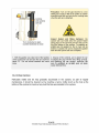
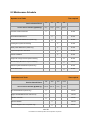
1
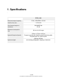
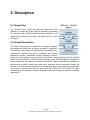
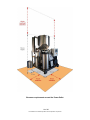
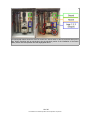
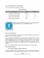
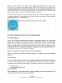
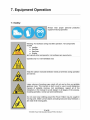
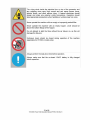
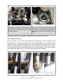
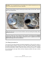
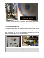
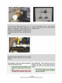
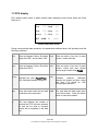
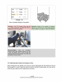
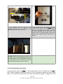
v1.09 Operation Manual
(Grid-tie model shown)
1 of 66
770-00082 Power Pallet Operation Manual (PP20/v1.09) Rev B
Table of Contents
1. Specifications
2. Relation to other Documents
2.1 Engine Manual
2.2 Engine governor manual
2.3 Generator manual
2.4 Grid-tie controller manual
3. List of Images and Icons
3.1 Warning icons
4. Introduction
4.1 Purpose of this manual
5. Description
5.1 General Use
5.2 General Description
6. Assembly and Installation
6.1 Packaging
6.2 Transporting
6.3 Storage
6.4 Installation Requirements
6.4.1 Facility Requirements
6.4.2 Final Assembly
6.4.2.1 Safety
6.4.2.2 Tools needed for assembly
6.4.2.3 Final assembly instructions
a) Hopper
c) Ash collection vessel
d) Engine
e) Grid-tie controller wiring
6.4.3 Post assembly testing
6.4.4 System Requirements
6.4.4.1 Hopper Loading
6.5 Dismantling, Storage and Waste Disposal
7. Equipment Operation
7.1 Safety
7.2 Tools
7.2.1 Provided
7.2.2 Not Provided
7.3 Feedstock
7.3.1 Feedstock Specifications
7.3.2 Feedstock consumption
7.4 Pre-Start Checks and Duties
2 of 66
770-00082 Power Pallet Operation Manual (PP20/v1.09) Rev B
7.4.1 Checklist of Pre-Start duties
7.4.2 Detailed Instructions of selected Pre-start Duties
7.4.2.1 Check Governor
7.4.2.2 Empty Ash Vessel
7.4.2.3 Empty Cyclone Ash Can
7.4.2.4 Clean Cyclone
7.4.2.5 Leak Testing the Power Pallet
7.4.2.5 Replacing graphite gaskets (if needed)
7.5 How to Operate the Power Pallet
7.5.1 Filling the Gasifier
7.5.2 Lighting the Gasifier
7.5.3 Running the Engine and Generating Electricity
7.5.3.1 Deep Sea Controller LED Status Indicator
7.5.4 Notes about Running the Power Pallet
7.5.4.1 White smoke from the flare
7.5.4.2. Bringing gasifier up to temperature
7.5.4.3 Temperature and gas suction rate
7.5.4.4 Longer starting time compared to gasoline or diesel fueled engines
7.5.4.5 Electrical loads and Gas Quality
7.6 PCU display during normal operation
7.7Detecting and resolving bridges
7.8 Switching Gas Output from Engine to Flare
7.9 Shutting Down the Power Pallet
7.10 Displayed Alarms and System Responses
8. Maintenance
8.1 Maintenance Safety
8.2 Maintenance Schedule
8.3 Operator Level Maintenance Instructions
8.3.1 Grate Basket Maintenance
8.3.1.1 Clinkers
8.3.2 Filter Maintenance (PP20 Only)
8.3.2.1 Drain Condensate from Filter
8.3.2.2 Change Gas Filter Media
8.3.2.3 Changing the filter media
8.3.2.4 Cleaning Foam Filters
8.3.3 Cowling and Cyclone Air Cleaning
8.3.8 Rotary Filter Maintenance (PP25 only)
8.3.4 Sensor Calibration
8.3.4.1 Oxygen Sensor Calibration
8.3.5 Engine Component Cleaning and Oil Change
8.3.6 Filter System Maintenance (PP25 only)
8.3.7 Manual Drying Bucket and Cyclone Cleaning
8.3.7.1 Drying Bucket
8.3.7.2 Cleaning the Cyclone
8.3.7.3 Cleaning the Gas Lines
8.3.8 Flare Maintenance
3 of 66
770-00082 Power Pallet Operation Manual (PP20/v1.09) Rev B
This publication may have been revised or updated since this copy was produced. To verify
that you have the latest revision, be sure to check the ALL Power Labs website:
www.allpowerlabs.com/support
If your publication is not there, please contact your customer service representative to get the
latest copy.
4 of 66
770-00082 Power Pallet Operation Manual (PP20/v1.09) Rev B
1. Specifications
PP20 v1.09
Electrical output capacity
50 Hz, 1500 RPM: 4–25 kW
Gasifier flow rate
11-52 m3/hr
Gas thermal output at
maximum
330,000 BTU/hr
97 kW
Biomass consumption
rate
50 Hz: 4.8–19.2 kg/hr
System Footprint (l×w×h)
System weight
136 cm × 178 cm ×193 cm
Footprint includes ash collection vessel beside the pallet.
The pallet itself is a 136cm square.
(893 kg) 1969 lbs
not including packaging for shipping or feedstock.
5 of 66
770-00082 Power Pallet Operation Manual (PP20/v1.09) Rev B
5. Description
5.1 General Use
The Grid-tied Power Pallet with Enclosure (henceforth, also
referred to as simply the Power Pallet) is intended for generating
AC electricity from locally available biomass feedstocks, and
supplying this electricity onto either the electric grid or a local
micro-grid.
5.2 General Description
The Power Pallet system is comprised of a gasifier integrated
with automation system and an engine coupled to a generator.
The purpose of the gasifier is to refine biomass feedstocks into a
clean-burning gaseous fuel that is compatible with internal
combustion engines. Gasification involves subjecting cellulosic
biomass to the processes of drying, pyrolysis, combustion, cracking, and reduction. Tar cracking
breaks down tar gases into carbon monoxide, hydrogen, and other light gases by exposure to
high temperatures, and reduction converts charcoal into carbon monoxide and hydrogen by
percolating the carbon dioxide and water vapor produced during combustion through hot
charcoal. The resulting combustible mixture of combustible gases and nitrogen from combustion
air is known as producer gas. Producer gas is made up of about 20% H2 and 20% CO, which
are both gaseous fuels that the internal combustion engine burns to generate power for grid tied
applications.
11 of 66
770-00082 Power Pallet Operation Manual (PP20/v1.09) Rev B
the hopper lid and to let air enter the system via the hopper. This will let air percolate
through the feedstock and purge the remaining gas in the hopper, drying bucket, and
PyroReactor for the remaining time.
● Disconnect the on-board battery.
● Empty the cyclone ash can, the ash collection vessel, and condensate vessel.
● Store the Power Pallet in a weather protected area and keep the electronics away from
moisture.
If the Power Pallet is stored for more than 6 months, all of the feedstock and charcoal must be
removed. The system must be inspected for proper operation. Inspection after storage includes
checking motors (grate shaker motor, ash grate motor and feedstock motor), engine coolant and
oil level. The feedstock and charcoal must be taken out and refilled with new material.
6.4 Installation Requirements
6.4.1 Facility Requirements
The facility to house the Power Pallet must have the following characteristics:
● Level flooring made of nonflammable material capable of supporting the weight of the
machine (listed in the Specifications section).
● The system is to be installed with a 92 cm clearance around the footprint of the machine
and at least a 173 cm clearance above the machine. See illustration on the next page.
● Sufficient ventilation through an exhaust hood with air flow capacity adhering to local
regulations.
● Install the CO meter provided with the Power Pallet and verify that it functions properly.
Have a CO meter near the operating floor at all times even when the machine is not in
operation and especially when performing maintenance.
● Operate the Power Pallet in locations having a max temperature of 40C and at an
altitude of 1000m or less. In case of different conditions please consult ALL Power Labs.
● Install the Power Pallet out of direct sunlight. UV from sunlight will damage parts over
time.
13 of 66
770-00082 Power Pallet Operation Manual (PP20/v1.09) Rev B
Clearance requirements around the Power Pallet.
14 of 66
770-00082 Power Pallet Operation Manual (PP20/v1.09) Rev B
1. Several smaller items must be attached to the
flare: the blowers and the igniter
2. When properly assembled, the assembly
should look as above. The single air blower
should bolt through the small truss, and the
double gas blowers should bolt through the larger
truss.
3. Attach the igniter to the top of the flare with the
machine screws that come with the igniter.
4. Mount the flare onto the flare stem. The flare
mount can be found on the base of the flare.
Attach the flare to the enclosure by sliding the
flare mount to the stem on the gasifier corner of
the Power Pallet, then bolt it on with the included
bolts. The combustion column of the flare should
be on the right side of this stem.
16 of 66
770-00082 Power Pallet Operation Manual (PP20/v1.09) Rev B
5. Attach the gas blower to the connecting pipe
using the flex coupler, which is fitted to both ends
with hose clamps.
6. Plug in all of the wires into their corresponding
blowers.
Testing When all of this is done, turn on the
Power Pallet, and briefly test the gas and air
blowers by turning them on and listening for a
sound at the blowers.
17 of 66
770-00082 Power Pallet Operation Manual (PP20/v1.09) Rev B
The photograph above shows the Grid-Tie control box, without wires on the left, and with wires on the
right. When consulting with an electrician to do the electrical portion of the installation of the Power
Pallet, please note the important terminals highlighted above.
19 of 66
770-00082 Power Pallet Operation Manual (PP20/v1.09) Rev B
7.2 Tools
Tools required for operation
7.2.1 Provided
● Starter charcoal— necessary for first start of gasifier
● Squirt bottle— useful for adding accelerant (flammable liquid) for lighting the gasifier
● Carbon Monoxide detector— for operator safety
7.2.2 Not Provided
● Fire extinguisher
● Handheld propane torch— for lighting the gasifier
● Ladder 6 ft (2m) or higher
● Heat-resistant gloves— for handling hot components and surfaces
● Metal pan— at least 10 liter capacity; this will be useful during maintenance, especially
when grate basket is being cleaned
● Metal rod or wooden stick, approximately 4 ft (1.25 m) long— for breaking feedstock
jams; stick should be fire resistant
● Metal ash rake— for cleaning out grate basket
● Shop vacuum cleaner— for cleaning out the grate basket and several maintenance
tasks
● Accelerant— for starting gasifier (e.g. lighter fluid, gasoline, diesel, kerosene, alcohol,
any other flammable fluid)
● Car Battery Charger— in case the battery charge is exhausted before the engine can be
started
7.3 Feedstock
7.3.1 Feedstock Specifications
Characteristic
Requirement
Particle size
0.5’’ – 1.5’’
Moisture content
less than 30% (Dry weight)
Ash content
less than 5%
24 of 66
770-00082 Power Pallet Operation Manual (PP20/v1.09) Rev B
12V DC Battery
Battery should be fully charged. Minimum voltage on
the battery is 12V, but 14V is preferred.
Governor throttle control check
(See Section 6)
Disconnect gas line to verify that governor is freely
moving.
Check that blowers work
Blowers are able to pull at least 50-60 units vacuum
on reactor. (Preac)
Oxygen sensor reading
Oxygen sensor number display should read 1.5 at
startup; do not run if error condition shown.
Flare Igniter
Igniter should turn ON when Preac (indicated on the
PCU display) is greater than 5. Check visually to
make sure the Igniter turns on (glows red).
Biomass Auger feed
Runs properly (not obstructed) and fills reactor with
feedstock. Alarm will sound if not working properly.
Clearance for rotational components
Make sure nothing is obstructing the rotational
components of the generator, engine, or gasifier (ie:
wood chips, tools, etc).
Flare or exhaust stack
Make sure nothing is obstructing the hot gas exits of
the exhaust and flare stack.
Check CO meter
CO meter is working and is near the operator.
Walk Around
Double check bungs, latches, gas connections and
bolts.
7.4.2 Detailed Instructions of selected Pre-start Duties
7.4.2.1 Check Governor
26 of 66
770-00082 Power Pallet Operation Manual (PP20/v1.09) Rev B
1) Disconnect the Novaflex hose between the
air mixer and the engine governor to drain
condensate and tars.
2) Inspect the engine governor throttle plate for
tar accumulation, and clean accordingly while the
tars are warm and soft. Reconnect Novaflex when
finished.
Use grease cutting cleaning solvents or alcohol to dissolve excess tar as needed.
7.4.2.2 Empty Ash Vessel
The ash collection vessel of the Power Pallet can collect between 12 and 24 hours of char
ash, depending on feedstock quality and load. The recommended time for emptying the ash
collection vessel is right before operating the Power Pallet, while the reactor is cool, but it
may also be emptied after an operating session if it is permitted to cool down until it is safe to
touch. Please be aware that detaching and opening the ash collection vessel poses a carbon
monoxide hazard. Make sure you are working in an area with good ventilation.
27 of 66
770-00082 Power Pallet Operation Manual (PP20/v1.09) Rev B
Precaution: Turn on the gas blowers to a low setting (3-4) so carbon monoxide does not vent
out into the working area when the vessel is detached.
1. Detach the ash collection vessel by loosening the sanitary clamp on the inlet tube. Take the
vessel to your disposal area.
2. Open the access port on top of the ash collection vessel by loosening the sanitary clamp,
and dump the ash out.
3. Close the access port, and re-attach the ash collection vessel. Be sure to establish
air-tight seals. Air leaks in this location increase the risk of explosion and reactor
component damage due to local combustion.
7.4.2.3 Empty Cyclone Ash Can
The cyclone ash can collects charcoal dust and ash separated out of the gas by the cyclone. It
has enough capacity to handle 14-24 hours of Power Pallet operation depending on feedstock
and settings, and should be emptied before each session. However, there is no way to measure
the level so check before 10 hours to make sure it does not fill and over pack. If it overpacks
this could damage the ash auger. Make sure there is adequate ventilation; this step is a carbon
monoxide hazard.
28 of 66
770-00082 Power Pallet Operation Manual (PP20/v1.09) Rev B
The cyclone with its ash can removed for maintenance. The hole under the cyclone can be
seen. Insert a pipe brush into this hole to purge any accumulated fouling.
7.4.2.5 Leak Testing the Power Pallet
The Power Pallet operator should carry out the following leak test before running the machine.
Air leaks are hazardous to the machine and to the user, risking internal fires and permanent
damage to the machine. Leaks are most likely to be introduced during assembly after
maintenance; thermal cycling can also potentially cause leaks. If a leak is detected, the operator
should examine every seal and joint that is opened during maintenance. Advanced leak
detection is explained in Section 3 of the Technician’s Handbook.
1) Turn on the automation assembly
2) Open the valve to the flare and close the valve
to the engine.
30 of 66
770-00082 Power Pallet Operation Manual (PP20/v1.09) Rev B
7.5 PCU display
PCU display briefly shows a splash screen before displaying main screen when the Power
Pallet is on:
Trst
TTTT Pcomb
PPP
Tred
TTTT Preac
PPP
RR Pfilt
PPP
Pratio
NEXT ALARM T:
00000
Power Pallet main screen
During normal steady-state operations, the parameters indicated above will generally meet the
following conditions.
Trst
Units are degrees Celsius. Should be Pcomb
higher than 800˚, but less than 1020˚
Units are tenths of an inch of water
column. Varies with load.
Tred
Units are degrees Celsius. Should be Preac
higher than 650˚C.
Units are tenths of an inch of water
column. Varies with load. Should
have a larger number than Pcomb.
Pratio
Indicates the ratio Pcomb/Preac * Pfilt
100. Should be between 20 and 60.
Indicates
pressure
difference
between the reactor and filter; varies
with load. P_filt should be <300
during engine operation.
NEXT
Press the button below the NEXT label ALARM
to advance to the next menu.
The ALARM label will flash when there
is an active alarm. Press the button
below to view active alarms.
T:
This area displays the number of
seconds the PCU has been powered
on and can be used to correlate
events with a timestamp in the data
log.
33 of 66
770-00082 Power Pallet Operation Manual (PP20/v1.09) Rev B
34 of 66
770-00082 Power Pallet Operation Manual (PP20/v1.09) Rev B
7.6 How to Operate the Power Pallet
7.6.1 Filling the Gasifier
1. Sift the dust and fines out of the bags of
provided charcoal using the ½” mesh provided
with the Power Pallet and pour it into the hopper.
2. Turn the main power switch ‘On’’ Wait a few
seconds for the Power Pallet automation to come
on.
Indication: The auger will activate and fill the
reactor with the charcoal. This can be observed
through the viewport on top of the PyroReactor if
desired.
3. Fill the hopper with APL-approved feedstock
and fasten the lid on the hopper, ensuring that the
lid is sufficiently secure to hold a gas tight seal.
Notes: When starting the Power Pallet for
the first time, fill the reactor with charcoal until
it reaches the tip of the fuel switch. If there
is not enough charcoal provided, use locally
sourced charcoal. The ideal feedstock for the
first start will have less than 15% moisture
content.
The sizes of both the charcoal and feedstock
pieces should be within the range of ½”-1 ½”.
Indication: When the reactor is full, the fuel
switch will automatically turn off the auger.
35 of 66
770-00082 Power Pallet Operation Manual (PP20/v1.09) Rev B
7.6.2 Lighting the Gasifier
1. Open the valve that leads to the flare, and close
the valve that leads to the engine.
2. Turn the gas blower until Preac reading
reaches 15, and adjust the air blower to just under
the gas blower setting. The igniter will turn on
once the Preac (Pressure in the reactor–indexed
value) reading exceeds 5. Note: The Grid Tied
Models will not have an engine key switch.
Indication: The igniter at the top of the flare stack
should start glowing.
Optional: Use the squirt bottle to add
approximately 15-25 mL of starting fluid (e.g.
diesel, gasoline, kerosene) through the lighting
port at the top of the reactor. This may help
slightly moist feedstocks light faster.
36 of 66
770-00082 Power Pallet Operation Manual (PP20/v1.09) Rev B
5. Use a hand-held lighting torch to light the
gasifier through the lighting port. Smoke and
steam should emerge from the flare stack.
6. When Trst (temperature at the restriction)
reaches 80˚C, cap the lighting port to stop any
additional air from entering
7. Increase the value of the gas blower to Indication: The flare will produce a low-pitched
increase Preac to -40 units. Once the flare is lit
increase the gas blower to the maximum setting.
Then increase the air setting until the combustion
descends into the flare tube.
roaring sound when the igniter lights the gas and
air mixture. If flames are visible above the flare,
slowly increase the value of the air blower until the
flames descend into the flare stack.
Note: startup should not take more than 20 minutes. Extended startup may deplete the battery.
See Section 7.5.4.2. under the heading Bringing the gasifier up to temperature.
7.5.3 Running the Engine and Generating Electricity
The Power Pallet off-grid and grid-tied systems have different engine startup procedures.
7.5.3.1 Off-Grid Models only
A. Starting the Engine
1. Quickly close the valve to the flare, and turn the gas and blower knobs to 0.
37 of 66
770-00082 Power Pallet Operation Manual (PP20/v1.09) Rev B
Genset” button on the Grid-tie controller and it will sync the generator to the
grid and close the contactor. You will now be exporting power to the grid.
Note: If the PCU sees that there is a problem then it will command the Grid-tie controller to
shut down. To clear the alarm, first clear the alarm on the PCU by pressing “Reset” then press
the red “Stop/Reset” button on the Grid-tie controller unit.
B. Shutting down the Grid-tie controller
1. To disconnect the generator from the grid, press the “Load Open/Close” button.
This will ramp down the amount of exported power to the grid and leave the
engine running.
2. To stop the engine, press the “Stop/Reset” button. The engine will run for a
cool down period then stop. To stop the engine immediately, press the “Stop/
Reset button twice. To stop the engine immediately press the emergency stop
button. This will shut the engine down immediately by cutting off power to the
engine ignition system. The emergency stop button will cause an alarm and
record an emergency stop event in the event log.
3. Switch the system over to flare mode (See section 5.5.5).
For further information please refer to the Grid-tie controller Operator’s Manual.
7.5.3.2.1 Deep Sea Controller LED Status Indicator
In the Grid Tie model, the LED status indicators signify the following:
LED Number Status
1
Bus Live
2
Generator Available
3
Generator Closed Aux
4
PLC Flag 1 (set in PLC to come on with 1 kW of Power)
7.5.4 Notes about Running the Power Pallet
7.5.4.1 White smoke from the flare
The first thing that comes out of the top of the flare during the lighting of the gasifier is white
smoke. This smoke is a mixture of tar gases and water vapor being driven out of the system
as it heats up. The heating element of the flare should eventually ignite the mixture once the
concentration of combustible gases is high enough to catch fire. If there is too much water in the
feedstock or the gas circuit, the flare may have difficulty lighting the smoke.
7.5.4.2. Bringing gasifier up to temperature
39 of 66
770-00082 Power Pallet Operation Manual (PP20/v1.09) Rev B
1. After shutting down the engine in the
instructions in section 7.5.3, close the valve to the
engine and open the valve to the flare.
2. Adjust the gas blower knob until Preac indicates
at least 5 units (igniter will not light at readings
below this), then adjust the air blower knob until
the flame descends into the flare and a low
roaring noise can be heard. Higher suction rates
can be used to maintain higher temperatures, as
needed.
Indication: When the igniter lights the smoke and
air mixture, the flame should descend into the
flare and produce a low roaring sound. If flames
are visible above the flare, increase the air blower
setting until the flames descend into the flare.
7.5.6 Gasifier Shutdown Procedure
Turn the blowers down until Preac is 1 and let the system run for 5 minutes (or until Tred is
650˚C) before completely shutting all valves off. This is because the gasifier will have enough
heat in it to continue to produce gas and smoke even after the engine is stopped; all of the
42 of 66
770-00082 Power Pallet Operation Manual (PP20/v1.09) Rev B
gas produced by this residual heat will result in the Power Pallet leaking smoke and carbon
monoxide rich gas into its surroundings. If the gasifier is very hot and is shut down without
a cool-down period, the large quantity of tar gases produced by the residual heat may even
condense on the feedstock in the pyrolysis column and may increase the risk of jams when
cooled down.
43 of 66
770-00082 Power Pallet Operation Manual (PP20/v1.09) Rev B
3) Drain the condensate vessel and close the
draincock securely.
The condensate vessel is located as indicated
above.
45 of 66
770-00082 Power Pallet Operation Manual (PP20/v1.09) Rev B
8.2 Maintenance Schedule
Operator Level Tasks
Time required
Service Interval Hours:
Service Interval Calendar (@7000hr/yr):
Pre-start Checks and Duties
20
62
125
500
Daily
3 Days
Weekly
Monthly
30 min
✓
Grate Basket Maintenance
✓
30 min
Packed Bed Filter Maintenance (PP20 only)
✓
30 min
Cowling and Cyclone Air Cleaning
✓
45 min
Rotary Filter Maintenance (PP25 only)
✓
30 min
Unplanned Operator Attendance
✓
60 min
Sensor Calibration
✓
30 min
Engine Oil Change and Component Cleaning
✓
60 min
Manual Drying Bucket and Cyclone Cleaning
✓
120 min
Filtration System Maintenance (PP25 only)
✓
60 min
Flare Maintenance
✓
45 min
Technician Level Tasks
Time required
Service Interval Hours:
Service Interval Calendar (@7000hr/yr):
1750
3500
7000
14000
3 Months
6 Mon hs
Yearly
2 Years
Air Lock Maintenance (PP25 only)
✓
30 min
Engine General Maintenance and Tune Up
✓
120 min
Replace O2 Sensor
✓
30 min
Overhaul Gasifier
✓
180 min
Overhaul Hopper & Air Lock (PP25 only)
✓
60 min
49 of 66
770-00082 Power Pallet Operation Manual (PP20/v1.09) Rev B
Turbo Maintenance (PP25 only)
30 min
✓
Replace Gasifier & Rotary Filter (PP25 only)
✓
180 min
Overhaul Hopper
✓
45 min
Overhaul Flare
✓
30 min
Overhaul Engine
✓
180 min
Replace Engine
✓
480 min
8.3 Operator Level Maintenance Instructions
Below are the instructions for operator level maintenance. The technician level maintenance
instructions out of the scope of the operation manual are described in the Technician’s
Handbook for the Power Pallet and should only be conducted by a trained technician.
8.3.1 Grate Basket Maintenance
The grate basket plays a crucial role in the production of combustible gases, and must be
maintained on a regular basis. Its primary role is to contain a bed of hot charcoal to support
reduction reactions. The gasifier will not start to produce usable gas until the reduction
reactions in the grate basket begin, but these cannot occur without charcoal filling the grate
basket. Secondly, by being shaken, it separates char ash from the rest of the charcoal to
maintain a good rate of gas flow. The grate basket is subjected to high temperatures and
shaking; when inspecting the basket, make sure the basket is intact, and that the holes are not
obstructed.
8.3.1.1 Clinkers
Clinkers are formed when the ash of the feedstock fuses together to form a hard rock-like
formation instead of remaining as dusty like ash. Clinker formation can increase when using
feedstocks with high ash content and high energy value. While gasifier temperatures and other
operating parameters (grate shaking, engine exhaust recycling rate, etc) can directly affect
clinker formation, it is important to understand that most all biomass combustion and gasification
systems have the same issue of clinker formation during their normal operating parameters,
ours is no different as this is a common issue among similar systems.
Check your grate basket after your first few runs to determine the clinker forming characteristics
of your feedstock, and adjust the maintenance schedule according to your observations. If
clinkers have accumulated in the basket, the grate basket must be cleaned out, and refilled. If
clinkers are physically attached to the inner wall of the gasifier or the grate basket, try very very
carefully to pry them off with a stick in a way that does not damage the equipment. If there is
damage, please contact [email protected].
50 of 66
770-00082 Power Pallet Operation Manual (PP20/v1.09) Rev B
If the clinker forming risk is low, this visual inspection can be less frequent for a given feedstock.
It is recommend to sift out the clinkers from the charcoal after emptying the reactor to reuse.
The grate basket shaking rate can be sped up to decrease the risk of clinkers fouling. If you
observe problems with your reduction reactions or gas quality, you may need to manually
remove the clinkers from the reactor. A possible indicator of clinker formation is that the
operating Pratio, indicated on the PCU, gradually decreases over the course of operation and
does not recover with grate shaking. This would be caused by a build-up of clinkers choking the
flow of gases, which lowers this pressure ratio across the grate basket.
Warning:
Carbon Monoxide Hazard
Warning: This procedure presents a carbon
monoxide hazard to the operator. Make sure
there is adequate ventilation, and keep the carbon
monoxide detector nearby at all times. To draw
carbon monoxide away from the work area, turn
the gas blowers to 5 or higher if smoke is visible.
Use safety goggles and gloves for touching hot
surfaces.
Recommendation:
We recommend using a small ash rake or
equivalent tool for this procedure.
51 of 66
770-00082 Power Pallet Operation Manual (PP20/v1.09) Rev B
that the condensate is full of tar and smells like smoke. Capture the condensate with a basin
under the drain bung.
1.
2.
3.
4.
5.
6.
7.
8.
9.
Close the valve to the engine and open the valve to the flare
Turn on the gas blower to a low setting to pull CO gas away from the work area
Remove the cyclone ash can for easier access to the gas inlet
Slide a small basin or pan under the gas inlet to catch the condensate
Open the sanitary clamp to drain condensate into the collection pan
Empty the pan as needed and place it back under the gas inlet
Disconnect the filter lid assembly from the valves to enable the filter to tilt
Tilt the filter to drain out any additional condensate
Push filter back into position, and reconnect all disconnected fittings, being careful to
establish airtight seals
8.3.2.2 Change Gas Filter Media
The packed bed filter is a 25 gal (94 liters) canister filled with sifted biomass as its filter media.
The filter separates out any particulates, tar that survived tar cracking, or condensate that failed
to be captured through the cyclone; as the producer gas ascends through the filter, it cools
further and condenses residual tars onto the sifted biomass. When the filter media needs a
change, it will be black and sticky, and will smell like smoke.
Example: this is what dirty foam filters look like.
The grate will need to be wire-brushed to clear the
perforations.
Example: the fine-grade sifted biomass at the top
of the filter under the foam discs looks like this
when it is due for changing.
53 of 66
770-00082 Power Pallet Operation Manual (PP20/v1.09) Rev B
Example: This sample of filter media is from a
filter that is over-due for changing. The biomass is
stuck together from excess tar, and has begun to
choke the flow of gases to the engine.
Example: This sample of filter media is just due
for changing. It is dark from having captured tar
on its surface, and is somewhat sticky, but is not
badly stuck together.
The filter comes with two perforated disc screens; one to hold the filter media off the bottom of
the filter canister, and one to hold down the two oiled foam discs that come with the filter, which
rest on top of the filter media to trap dust particles. The top perforated disc holds the foam discs
down against the suction of the engine. Without this disc, the vacuum from the engine will pull
the foam into the gas outlet, causing a serious bottleneck for the gas to travel through that will
ultimately choke the engine.
Perforated discs and foam filters that come with the gas filter.
The step-by-step instructions have a corresponding video at our channel on YouTube.
8.3.2.3 Changing the filter media
54 of 66
770-00082 Power Pallet Operation Manual (PP20/v1.09) Rev B
1) Set one of the screens on the tabs that are
about 5 inches (13 cm) above the bottom. This
space below the bottom grate is reserved for
collecting condensate in the filter. Check the
condensate level through the indicator tube. Drain
condensate through the gas inlet at the bottom of
the filter.
Important: When changing the filter media, use
a wire brush to clear blocked holes in the lower
screen. Blocked holes will choke the flow of gas.
2) Add the layers of sifted biomass as shown in
the image above:
3) Insert the black (coarse, 45 dpi) foam disc,
then the green (fine, 65 dpi) foam disc, and then
gently insert the perforated steel screen on top.
Be careful to not damage the gasket around the
upper lip of the filter drum when inserting and
removing the screen.
4) Be sure not to overfill the filter. There should be
a 2 inch (5cm) space at the top of the filter.
8 inches of fuel grade biomass at the bottom;
8 inches of medium sifted biomass in the middle;
6 inches of fine sifted biomass on top.
Use the screens provided.
The filter is only designed for filtering gas produced from cellulosic biomass. The filter is not
sufficient for filtering the gas products of coal, peat, plastics, or municipal solid waste (MSW);
none of these feedstocks are suitable for use in the Power Pallet.
8.3.2.4 Cleaning Foam Filters
The foam filters that reside at the top of the gas filter will gradually accumulate tar condensates,
and should be cleaned each time you replace the filter media. To clean the foam filters, you will
need a basin, and plenty of alcohol. Clean the foam filters according to the following procedure:
1. Put alcohol and foam disc in basin. Cover with lid and let alcohol dissolve the tars for
a few minutes.
2. Wash the foam disc by squeezing and working the alcohol through the foam.
55 of 66
770-00082 Power Pallet Operation Manual (PP20/v1.09) Rev B
8.3.4.1 Oxygen Sensor Calibration
Every oxygen sensor must be calibrated before the first use or whenever it is replaced. ALL
Power Labs performs this calibration on every Power Pallet before shipping. If the oxygen
sensor is exposed to water, temperatures higher than its operating temperature, or particulate
buildup occurs, the sensor will not work properly without recalibration. Follow these procedures
to calibrate the oxygen sensor:
1. Disconnect the gas line from the governor. Then turn the key switch for 5 seconds
as if you are attempting to start the engine. This will purge the exhaust out of the
exhaust manifold and expose the oxygen sensor to air.
2. Turn off the Power Pallet using the main power switch.
3. Disconnect O2 sensor RS232 connector from inside the automation enclosure. (See
graphic)
57 of 66
770-00082 Power Pallet Operation Manual (PP20/v1.09) Rev B
4. Power on the Power Pallet with the sensor disconnected. All three digits on the
lambda meter will light up and the lit LED bar will sweep once through all LEDs on
the display. Then the status light will turn red and the numeric display will read “E2”.
This indicates that no sensor is detected.
5. Leave unit powered off for 30 seconds.
6. Turn on the Power Pallet.
7. The lit LED should again sweep through all the LEDs in the display, but instead of an
error the display will read “HTR” (which stands for ‘heater’). This indicates that the
sensor is being heated up to operating temperature. After 30-60 seconds, the display
will switch to “CAL”, indicating that the sensor is being calibrated. A few seconds
later, the meter will begin displaying air/fuel ratio.
8. Re-attach the oxygen sensor cable.
With the calibration process above completed, the meter is now ready for use.
Important: If you power up the meter without a sensor connected, your calibration will be
reset (see step #4 above).
8.3.4.2 Pressure Sensor Calibration
Pressure sensors should be re-calibrated if the zero-point drifts or when the PCU is first used.
Calibrate the pressure sensors through the following process:
1. Remove the pressure tubing from the barbs on the PCU’s pressure sensors.
2. Turn on the Power Pallet.
3. Scroll through the menus (by pressing “Next”) until you reach the screen that says
“Calibrate Pressure Sensors to Zero?”
4. Choose “Yes.”
5. Push the pressure tubing onto the barbs on the PCU’s pressure sensors.
a. Make sure that the each tube is connected to the correct/corresponding sensor.
b. Make sure that the pressure tube is attached to the top/front barb on each sensor
and that the back/lower barb is exposed to the atmosphere.
c. Make sure that the tubing is pushed all the way down so that it contacts the
square body of the sensor.
8.3.5 Engine Component Cleaning and Oil Change
Take off the governor and clean the backside of the governoras well as anything seen in
the inlet to the engine. Replace any paper gaskets between the governor and the engine as
needed.
Change the engine oil and the oil filter. Refer to the PSI 3.0L Industrial Engine Service Manual
for further instructions.
8.3.6 Filter System Maintenance (PP25 only)
58 of 66
770-00082 Power Pallet Operation Manual (PP20/v1.09) Rev B
8.3.7.2 Cleaning the Cyclone
Take off the cyclone catch can and remove the cyclone from the gas cowling. Use a stick or
scraping device to remove any soot accumulation in the inside of the cowling and the cyclone.
8.3.7.3 Cleaning the Gas Lines
Remove the corrugated gas lines connected to the gas filter at either end (these 3 gas lines
connect from the gas filter to the blowers, engine, and drying bucket. Straighten the gas lines
and use a stick or wire brush to knock off any accumulation inside.
8.3.8 Flare Maintenance
The gas blowers will gradually become fouled with tar because they draw the gas through the
gasifier during startup, when these gases are rich in tar. Adjust the maintenance interval down if
you do frequent start-ups, since the startup period is when these blowers accumulate the most
fouling. Detach the blowers from the Power Pallet to clean the insides of the blower housings
with alcohol.
The following procedure is shown on one blower; repeat for both blowers.
61 of 66
770-00082 Power Pallet Operation Manual (PP20/v1.09) Rev B
Rinse and wipe the parts dry when clean, then re-assemble the blowers and re-attach them to
the flare, being careful to correctly wire them to the automation wire terminals.
63 of 66
770-00082 Power Pallet Operation Manual (PP20/v1.09) Rev B
Reader’s Notes
(page intentionally left blank)
64 of 66
770-00082 Power Pallet Operation Manual (PP20/v1.09) Rev B
Reader’s Notes
(page intentionally left blank)
65 of 66
770-00082 Power Pallet Operation Manual (PP20/v1.09) Rev B
Questions?
Visit us at:
www.allpowerlabs.com/support
or by email:
[email protected]
66 of 66
770-00082 Power Pallet Operation Manual (PP20/v1.09) Rev B