1
SERVICE MANUAL
6M63N CHASSIS
6M63N/A/E
Design and specifications are subject to change without prior notice.
(Only Referrence)
Description:
SERVICE MANUAL
MODEL.
6M63N
Brand Name:
JOB NO.
Engineering Dept:
SIZE:A5
Artwork By:
Date:
Checked By:
Date:
Approved By:
Date:
2013-07-18
Content--------------------------------------------------------------2
3-8
9
10-15
16
17-18
19-26
27-46
47-49
50-59
50-58
LED 6M63N
DTV:ATSC
ATV: NTSC-M
VHF LOW 2~B
VHF HIGH C~W+11
VHF
W+12~69
55.25MHz ~ 127.25MHz
133.25MHz ~ 313.25MHz
367.25MHz ~ 801.25MHz
DTV: 57-803MHZ
North
TOSHIBA CODE
Component
1
1
NO
NO
ET
30
40
For 22” LED
For 24” LED
65
For 32” LED
NO
40
40
3
2
1
4.2
50
0.5
12000
80
40
3
40
NO
YES
8
6
46
46
NO
Standard
Standard
30
English
Dynamic backlight
Off
-7-
4
2
4
0
40
70
0
40
70
0
40
40
85
-Y0
50
30000
-8-
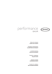
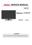
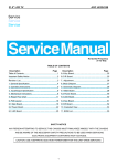
Block Diagram for 6306/3393标准板 series
Silicon tuner
on board
IF+/-
SYSTEM
POWER SUPPLY
SPI
FLASH
32Mb
IF+/-
TUNER
Side Terminal
KEY PAD, IR Receiver
USB1
Digital
Demo
Analog
Demo
6306/3393
LVDS,DIM
ON/OFF
Ultra high speed/performance 32-bi RISC
CPU
Digital and Analog Front-End Demodulator
Multi-standard A/V Format Decoder
Support HDMI1.4 CEC/ARC and 3D Format in
put
USB1
HDMI data
HDMI1
LCD/LED
PANEL
Composit
e
USB2
AUDIO OUT
Component
RGB
DIGITAL
AUDIO OUT
HDMI data
Audio
L/R
TPA3110
8W + 8W
HP AMP.
TPA6138
Rear Terminal
S/PDIF
Output
USB2
HDMI2(MHL)
PC-VGA
HDMI3
PC-Audio
L/R
Component
Earphone
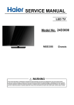
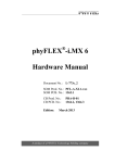
IC Block Diagram
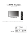
U5ˈU11 3.3V/1A 3-TERMINAL POSITIVE VOL TAGEREGULATOR
U4(1.8V/1A SOT-252) AS1117-ADJ
-10-
LD1117-3.3 SOT-223
U1
(SYNCHRONOUS BUCK REGULATOR) AOZ3015
VCC
UVLO
& POR
EN
VIN
LDO
Regulator
OTP
+
ISen
Reference
& Bias
Softstart
–
Q1
ILimit
+
+
EAmp
FB
–
–
PWM
Control
Logic
PWM
Comp
+
VOUT
Output
Sense
Level
Shifter
+
FET
Driver
LX
Q2
COMP
500kHz
Oscillator
PEM Control
Logic
Vref
Iinfo
PWM/PEM
Master Control
Iinfo
PGND
AGND
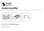
U3
(SYNCHRONOUS BUCK REGULATOR) MP1470
IN
+
-
VCC
Regulator
RSEN
Currrent Sense
Amplifer
Bootstrap
Regulator
Oscillator
HS
Driver
+
1.2pF
EN
6.5V
FB
Reference
47pF
20k
+
+
-
500k
1MEG
Error Amplifier
BST
Current Limit
Comparator
Comparator
On Time Control
Logic Control
SW
VCC
LS
Driver
GND
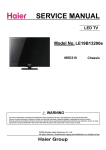
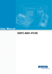
IC Block Diagram
U6(ATSC DIGITAL TV SYSTEM-ON-CHIP) MSD3393LU
RXB1N
RXB1P
1
102
2
101
RXB2N
RXB2P
AVDD_MOD33
RXACKN
RXACKP
RXA0N
RXA0P
RXA1N
RXA1P
RXA2N
RXA2P
HSYNC0
BIN0P
GIN0P
GIN0M
RIN0P
VSYNC0
AVDD_ADC33
BIN1P
SOGIN1
GIN1P
GIN1M
RIN1P
VSYNC1
CVBS1
CVBS0
VCOM
CVBSOUT1
VDDC
AVDD_AU33
LINEIN_R0
LINEIN_L0
LINEIN_R1
LINEIN_L1
AUVAG
3
AUREFM
Pin 1
100
SAR1
SAR0
AVDD_MOD33
DP_P1
DM_P1
4
99
5
98
6
97
7
96
8
95
9
94
10
93
11
92
12
91
13
90
14
89
15
88
16
87
17
86
18
85
19
84
20
83
21
82
22
81
IRIN
CEC
GND
DDCA_CK
DDCA_DA
ARC
SCK
CSZ
SDI
SDO
PWM0
PWM1
HOTPLUGA
23
80
HOTPLUGD
24
79
25
78
26
77
27
76
28
75
29
74
30
73
31
72
32
71
LVB0M
LVB0P
LVB1M
LVB1P
LVB2M
LVB2P
AVDD_MOD33
LVB3M
LVB3P
33
70
34
69
35
68
36
67
37
66
38
65
-12-
DP_P0
DM_P0
RESET
GPIO64
LVA0M
LVA0P
LVA1M
LVA1P
LVA2M
LVA2P
IC Block Diagram
U300(512MB DDR2-1066 SDRAM) NT5TU32M16DG
-13-
IC Block Diagram
U103(32M BIT CMOS SERIAL FLASH)SOP8
A dd ress
G enerator
M em ory A rray
P ag e B uffer
S I/
S IO0
D ata
R egister
Y-D ecod er
S O /S IO1
C S #,
W P #,
H O LD#
S CLK
S R AM
B uffer
M ode
Logic
S tate
M achine
S en se
A m plifier
HV
G enerator
C lock G enerator
O utput
B uffer
-14-
IC Block Diagram
U12( 15W STEREO AUDIO POWER AMPLIFIER) TPA3110
ÐÉÐ øÌÍÍÑÐ÷ ÐßÝÕßÙÛ
øÌÑÐ Ê×ÛÉ÷
ÍÜ
ÚßËÔÌ
ï
îè
î
îé
Ô×ÒÐ
Ô×ÒÒ
Ùß×Òð
Ùß×Òï
í
îê
ì
îë
ë
îì
ê
îí
ßÊÝÝ
ßÙÒÜ
ÙÊÜÜ
ÐÔ×Ó×Ì
é
îî
è
îï
ç
îð
ïð
ïç
ïï
ïè
ïî
ïé
ïí
ïê
ïì
ïë
Î×ÒÒ
Î×ÒÐ
ÒÝ
ÐÞÌÔ
ÐÊÝÝÔ
ÐÊÝÝÔ
ÞÍÐÔ
ÑËÌÐÔ
ÐÙÒÜ
ÑËÌÒÔ
ÞÍÒÔ
ÞÍÒÎ
ÑËÌÒÎ
ÐÙÒÜ
ÑËÌÐÎ
ÞÍÐÎ
ÐÊÝÝÎ
ÐÊÝÝÎ
Ð×Ò ÚËÒ Ì×
Ð×Ò
з²
Ò«³¾»®
×ñÑñÐ
ÍÜ
ï
×
͸«¬¼±©² ´±¹·½ ·²°«¬ º±® ¿«¼·± ¿³° øÔÑÉ ã ±«¬°«¬- Ø·óÆô Ø×ÙØ ã ±«¬°«¬»²¿¾´»¼÷ò ÌÌÔ ´±¹·½ ´»ª»´- ©·¬¸ ½±³°´·¿²½» ¬± ßÊÝÝò
ÚßËÔÌ
î
Ñ
Ñ°»² ¼®¿·² ±«¬°«¬ «-»¼ ¬± ¼·-°´¿§ -¸±®¬ ½·®½«·¬ ±® ¼½ ¼»¬»½¬ º¿«´¬ -¬¿¬«-ò ʱ´¬¿¹»
½±³°´·¿²¬ ¬± ßÊÝÝò ͸±®¬ ½·®½«·¬ º¿«´¬- ½¿² ¾» -»¬ ¬± ¿«¬±ó®»½±ª»®§ ¾§ ½±²²»½¬·²¹
ÚßËÔÌ °·² ¬± ÍÜ °·²ò Ѭ¸»®©·-»ô ¾±¬¸ -¸±®¬ ½·®½«·¬ º¿«´¬- ¿²¼ ¼½ ¼»¬»½¬ º¿«´¬- ³«-¬
¾» ®»-»¬ ¾§ ½§½´·²¹ ÐÊÝÝò
ÒßÓÛ
ÜÛÍÝÎ×ÐÌ×ÑÒ
Ô×ÒÐ
í
×
б-·¬·ª» ¿«¼·± ·²°«¬ º±® ´»º¬ ½¸¿²²»´ò Þ·¿-»¼ ¿¬ íÊò
Ô×ÒÒ
ì
×
Ò»¹¿¬·ª» ¿«¼·± ·²°«¬ º±® ´»º¬ ½¸¿²²»´ò Þ·¿-»¼ ¿¬ íÊò
Ùß×Òð
ë
×
Ù¿·² -»´»½¬ ´»¿-¬ -·¹²·º·½¿²¬ ¾·¬ò ÌÌÔ ´±¹·½ ´»ª»´- ©·¬¸ ½±³°´·¿²½» ¬± ßÊÝÝò
Ùß×Òï
ê
×
Ù¿·² -»´»½¬ ³±-¬ -·¹²·º·½¿²¬ ¾·¬ò ÌÌÔ ´±¹·½ ´»ª»´- ©·¬¸ ½±³°´·¿²½» ¬± ßÊÝÝò
Ð
ßÊÝÝ
é
ßÙÒÜ
è
ß²¿´±¹ -«°°´§
ÙÊÜÜ
ç
Ñ
Ø·¹¸ó-·¼» ÚÛÌ ¹¿¬» ¼®·ª» -«°°´§ò Ò±³·²¿´ ª±´¬¿¹» ·- éÊò ß´-± -¸±«´¼ ¾» «-»¼ ¿-«°°´§ º±® ÐÔ×Ó×Ì º«²½¬·±²
ÐÔ×Ó×Ì
ïð
×
б©»® ´·³·¬ ´»ª»´ ¿¼¶«-¬ò ݱ²²»½¬ ¿ ®»-·-¬±® ¼·ª·¼»® º®±³ ÙÊÜÜ ¬± ÙÒÜ ¬± -»¬
°±©»® ´·³·¬ò ݱ²²»½¬ ¼·®»½¬´§ ¬± ÙÊÜÜ º±® ²± °±©»® ´·³·¬ò
Î×ÒÒ
ïï
×
Ò»¹¿¬·ª» ¿«¼·± ·²°«¬ º±® ®·¹¸¬ ½¸¿²²»´ò Þ·¿-»¼ ¿¬ íÊò
Î×ÒÐ
ïî
×
б-·¬·ª» ¿«¼·± ·²°«¬ º±® ®·¹¸¬ ½¸¿²²»´ò Þ·¿-»¼ ¿¬ íÊò
ÒÝ
ïí
ÐÞÌÔ
ïì
×
п®¿´´»´ ÞÌÔ ³±¼» -©·¬½¸
ÐÊÝÝÎ
ïë
Ð
б©»® -«°°´§ º±® ®·¹¸¬ ½¸¿²²»´ Øó¾®·¼¹»ò η¹¸¬ ½¸¿²²»´ ¿²¼ ´»º¬ ½¸¿²²»´ °±©»®
-«°°´§ ·²°«¬- ¿®» ½±²²»½¬ ·²¬»®²¿´´§ò
ÐÊÝÝÎ
ïê
Ð
б©»® -«°°´§ º±® ®·¹¸¬ ½¸¿²²»´ Øó¾®·¼¹»ò η¹¸¬ ½¸¿²²»´ ¿²¼ ´»º¬ ½¸¿²²»´ °±©»®
-«°°´§ ·²°«¬- ¿®» ½±²²»½¬ ·²¬»®²¿´´§ò
ÞÍÐÎ
ïé
×
Þ±±¬-¬®¿° ×ñÑ º±® ®·¹¸¬ ½¸¿²²»´ô °±-·¬·ª» ¸·¹¸ó-·¼» ÚÛÌò
ÑËÌÐÎ
ïè
Ñ
ÐÙÒÜ
ïç
ß²¿´±¹ -·¹²¿´ ¹®±«²¼ò ݱ²²»½¬ ¬± ¬¸» ¬¸»®³¿´ °¿¼ò
Ò±¬ ½±²²»½¬»¼
Ý´¿--óÜ Øó¾®·¼¹» °±-·¬·ª» ±«¬°«¬ º±® ®·¹¸¬ ½¸¿²²»´ò
б©»® ¹®±«²¼ º±® ¬¸» Øó¾®·¼¹»-ò
ÑËÌÒÎ
îð
Ñ
Ý´¿--óÜ Øó¾®·¼¹» ²»¹¿¬·ª» ±«¬°«¬ º±® ®·¹¸¬ ½¸¿²²»´ò
ÞÍÒÎ
îï
×
Þ±±¬-¬®¿° ×ñÑ º±® ®·¹¸¬ ½¸¿²²»´ô ²»¹¿¬·ª» ¸·¹¸ó-·¼» ÚÛÌò
Þ±±¬-¬®¿° ×ñÑ º±® ´»º¬ ½¸¿²²»´ô ²»¹¿¬·ª» ¸·¹¸ó-·¼» ÚÛÌò
ÞÍÒÔ
îî
×
ÑËÌÒÔ
îí
Ñ
ÐÙÒÜ
îì
Ý´¿--óÜ Øó¾®·¼¹» ²»¹¿¬·ª» ±«¬°«¬ º±® ´»º¬ ½¸¿²²»´ò
б©»® ¹®±«²¼ º±® ¬¸» Øó¾®·¼¹»-ò
ÑËÌÐÔ
îë
Ñ
Ý´¿--óÜ Øó¾®·¼¹» °±-·¬·ª» ±«¬°«¬ º±® ´»º¬ ½¸¿²²»´ò
ÞÍÐÔ
îê
×
Þ±±¬-¬®¿° ×ñÑ º±® ´»º¬ ½¸¿²²»´ô °±-·¬·ª» ¸·¹¸ó-·¼» ÚÛÌò
ÐÊÝÝÔ
îé
Ð
б©»® -«°°´§ º±® ´»º¬ ½¸¿²²»´ Øó¾®·¼¹»ò η¹¸¬ ½¸¿²²»´ ¿²¼ ´»º¬ ½¸¿²²»´ °±©»®
-«°°´§ ·²°«¬- ¿®» ½±²²»½¬ ·²¬»®²¿´´§ò
ÐÊÝÝÔ
îè
Ð
б©»® -«°°´§ º±® ´»º¬ ½¸¿²²»´ Øó¾®·¼¹»ò η¹¸¬ ½¸¿²²»´ ¿²¼ ´»º¬ ½¸¿²²»´ °±©»®
-«°°´§ ·²°«¬- ¿®» ½±²²»½¬ ·²¬»®²¿´´§ò
-15-
-16-
6M63N/A/E
6M63N
Service Adjustment
(V0. 0)
1
Factory Manual
1 、How to enter and exit factory mode
1.1.1 Press Source button, and then press digital button “3”, “1”, “9”, “5” in turns to enter the factory menu.
Press Ç and È button to choose the item ,press OK button to enter the submenu and press Æ button to adjust the
value.
In the factory mode, press “menu” key can exit the factory mode.
2 、How to adjust White Balance
2.1 ADC ADJUST
Before adjusting, enter the channel you want to adjust and input adjust signal (YPBPR channel: 576Pand720P
&100% color bar; VGA channel: 1366*768 & tessellated white and black ). Select AUTO ADC, press u button
to auto adjust the ADC value.
100% color bar
tessellated white and black
Note: 1、The YPBPR and VGA’s Auto White Balance adjust (AUTO ADC) must be done on the product line.
2、In YPBPR channel ,must adjust the SD and HD two modes.
2
2.2 W/B ADJUST
Enter factory mode, select W/B ADJUST, go to the “MODE” item to select the channel which you want to adjust
then select the color temperature (Medium, Warm, Favorite,Cool). Then press q Key to go to these items you
want to adjust:
R Gain
G Gain
B Gain
R Offset
G Offset
B Offset
Press t or u key can adjust the value to the best effect.
COPY ALL : Copy there values to all source!
3、How to update software
3.1 Open MSTAR ISP Utility tool
3.2、Connect the tool to the device ,turn on TV .press “Connect”。
3
3.3、press “Read” to choose the “merge.bin” file .
3.4、Press “Auto”, set parameter。
3.5、press “Run”。
4
4、Update software (by USB):
Copy the new software (name by “MERGE.bin”) to the root directory of USB drive. Plug the drive to the USB
socket (if there are two USB socket, make sure you use the socket 1). Enter MENU and select SETUP item , select
“Software Upgrade(USB)” item and press OK button to begin update. TV set will restart when finish. Note, you
need to restart the TV set again by AC power.
Note: We suggest you need to do “Restore Default” after software update.
5、HDCP KEY burning:
5
5.1、Connect burning tool to main board P4. Open ISP4.5.3.5 tool
5.2、Turn on TV then click “connect”
5.3、Click “read” to select the sofrware
5.4、Click “HDCP”then set the following items, the address should be 0X390000
5.5、Click “AUTO” then set the following items
5.6、When finished setting .click “RUN”to burn HDCP KEY
6
ADC ADJUST
MODE
R-GAIN
G-GAIN
B-GAIN
R-OFFSET
G-OFFSET
B-OFFSET
AUTO ADC
W/B
ADJUST
MODE
TEMPERATURE
Medium/Warm/Cool
R-GAIN
G-GAIN
B-GAIN
R-OFFSET
G-OFFSET
B-OFFSET
COPY ALL
Panel control
TI Mode
On/Off
On/Off : adjust the TI mode of LVDS
LVDS
On/Off
odd-even channel switch
Port
On/Off
Parameter
OVER SCAN
Startup Sourrce
Left Crop
These items can adjust the size of the
Right
Top/Bottom/Left/Right
Up
OSD
Input
Language
Sourrce
Crop
Crop
Down
SYSTEM SETTING
8(24bit) / 10(30bit)
Crop
Factory hot key enable
Fac.Hotkey
On/Off
Default
English/ SPANISH / PORTUGUESE / FRENCH
Language
Country
Brazil/Argentina/Peru/Chile
Power On Mode
Standby/Memory/Power On/
Aging Mode
On/Off
Restore Default
reset all value to factory default
Preset channels
reset channel to default
English
On/Off
FRENCH
On/Off
PORTUGUESE
On/Off
SPANISH
On/Off
AV1
On/Off
AV2
On/Off
HDMI 1
On/Off
HDMI 2
On/Off
HDMI 3
On/Off
HDMI 4
On/Off
YUV 1
On/Off
YUV 2
On/Off
PC-RGB
On/Off
7
Analog Curve
Mode
BRIGHTNESS
CONTRAST
SATURATION
HUE
SHARPNESS
VOLUME
PICTURE MODE
Startup Source
MODE
Natural/Cinema/Favorite/Game/Dynamic
BRIGHTNESS
CONTRAST
COLOR
SHARPNESS
TINT
Mac Address Update
HDCP Key Update
CI PLUS Key UPDATE
SOFTWARE UPDATE(USB)
SW
INFORMATION
SSC SETTING
VIF INITIALIZATION
PIP/POP
PIP/POP
On/Off
PIP Border Width
3D
3D
On/Off
3D Output Mode
Side-By- Side/Top-and-Bottom/
CUSTOMER SETTING
WHITE PATTERN
Off/White/Red/Green/Blue/Black
WDT
On/Off
PVR RECORD ALL
On/Off
UART ENABLE
On/Off
CI+Credential Mode
Power on
LOGO
Stagecraft 1.2 certification
Audio Hidev Mode
Others
Netfix Key Update
8
User Manual
29E52
Size:A5
Description:
Job No.
MODEL:
MANUAL(6M63N)
1303158M
29E52
REV:
Brand Name:
SKYWORTH
P/No.
Scale:
Engineering Dept:
Artwork By:
Date:
Checked By:
Date:
Approved By:
Date:
2013-6-20
CONTENT
CONTENT
WARNING AND PRECAUTION ......................................................................... 1-3
FUNCTIONS AND FEATURES ............................................................................. 4
EXTERNAL SCHEMATIC AND INSTALLATION ................................................ 5-8
Front Panel .................................................................................................... 5
Back Panel .................................................................................................... 6
Remote Control .......................................................................................... 7-8
MENU CONTROL ........................................................................................... 9-16
Menu Operation ...........................................................................9
Picture .......................................................................................................... 9
Audio .......................................................................................................... 10
Channel ...................................................................................................... 10
Setup ........................................................................................................... 11
Time ............................................................................................................. 12
Lock ............................................................................................................. 12
PC ................................................................................................................ 13
USB Menu ................................................................................................... 14
USB CONTROL ............................................................................................. 15-16
Video Menu .................................................................................................. 15
Music Menu ................................................................................................. 15
Photo Menu ................................................................................................. 16
Text Menu .................................................................................................... 16
TROUBLESHOOTING ........................................................................................ 17
SPECIFICATIONS .............................................................................................. 18
WARNING AND PRECAUTION
Read all of the instructions before operating the set. Keep these instructions well for later use.
Warning
Only use attachments/accessories specified or provided by the manufacturer (such as the
exclusive supply adapter, battery etc).
Please refer the information on exterior back enclosure for electrical and safety information
before installing or operating the apparatus.
To reduce the risk of fire or electric shock, do not expose this apparatus to rain or moisture.
The ventilation should not be impeded by covering the ventilation openings with items, such
as newspaper, table-cloths, curtains, etc.
The apparatus shall not be exposed to dripping or splashing and that no objects filled with
liquids, such as vases, shall be placed on the apparatus.
For the terminals marked with symbol of “
” may be of sufficient magnitude to constitute a
risk of electric shock. The external wiring connected to the terminals requires installation by
an instructed person or the used of ready-made leads or cords.
To prevent injury, this apparatus must be securely attached to the floor/wall in accordance with
the installation instructions.
Danger of explosion if battery is incorrectly replaced. Replace only with the same or
equivalent type.
The battery (battery or batteries or battery pack) shall not be exposed to excessive heat such
as sunshine, fire or the like.
Excessive sound pressure from earphones and headphones can cause hearing loss.
Listening to music at high volume levels and for extended durations can damage one’s hearing.
In order to reduce the risk of damage to hearing, one should lower the volume to a safe,
comfortable level, and reduce the amount of time listening at high levels.
The mains plug or appliance coupler is used as disconnect device, it shall remain readily
operable.
When not in use and during movement, please take care of the power cordset, e.g. tie up the
power cordset with cable tie or something like that. It shall be free from sharp edges and the
like that can cause abrasion of the power cordset. When put into use again, please make sure
the power cordset being not damaged, If any damages found, please look for the service
person to replace the power cordset specified by the manufacturer or have the same
characteristics as the original one.
Explanation of symbol, marking, signal lamp or similar means indicate that apparatus is
completely disconnected from the mains.
Attention should be drawn to environmental aspects of battery disposal.
No naked flame sources, such as lighted candles, should be placed on the apparatus.
To prevent the spread of fire, keep candles or other open flames away from this
product at all times.
Each USB terminal shall be loaded with 500mA under normal operation.
-1 -
WARNING AND PRECAUTION
Important Information For Australia
Using cabinets or stands recommended by the manufacture of the television.
Only using furniture that can safety support the television.
Ensuring the television is not overhanging the edge of the supporting furniture.
Not placing the television on tall furniture(for example, cupboards or bookcases) without
anchoring both the furniture and the television to a suitable support.
Not standing the television on cloth or other materials placed between the television and
supporting furniture.
Educating children about the dangers of climbing on furniture to reach the television or its
controls.
The apparatus should be provided with a restraining device such as a fixing point to facilitate
restraining the apparatus from toppling forward.
WEEE Directive
Correct Disposal of this product. This marking indicates that this product should not be
disposed with other household wastes throughout the EU. To prevent possible harm to the
environment or human health from uncontrolled waste disposal, recycle it responsibly to
promote the sustainable reuse of material resources. To return your used device, please use the
return and collection systems or contact the retailer where the product was purchased. They
can take this product for environmental safe recycling.
Positioning The TV Set
Install Display on solid horizontal surface such as a table or desk. For ventilation, leave a
space of at least 10cm free all around the set. To prevent any fault and unsafe situations,
please do not place any objects on top of the set. This apparatus can be used in tropical
and/or moderate climates.
Fixing the rear of enclosure to wall. (only for AU market)
10CM
10CM
10CM
10CM
-2-
WARNING AND PRECAUTION
Operating Environment
Do not install this equipment in a confined space such as a bookcase or similar unit.
Do not use the set near damp, and cold areas, protect the set from overheating.
Keep away from direct sunlight.
Do not use the set near dust place.
Do not attach candle to accessible opening area, to avoid flammable foreign material from
entering the TV.
Precautions For Using Remote Control
Use the remote control by pointing it towards the remote sensor. The items between the
remote control and the remote sensor will interfere the normal operation.
Do not make remote control vibrate violently. Also, do not splash liquid on the
remote control, also do not put the remote control in high humidity place.
Do not place remote control under direct sunlight which will cause deformation
of the unit by heat.
When the remote sensor is under direct sunlight or strong lighting, the remote
control will do not work. If so please change the lighting or TV's position, or
operate the remote control closer to the remote sensor.
Precautions For Using Battery
Improper using of the battery will cause leakage. So please do as the following methods
and use carefully.
1. Please note the batteries ' polarity, to avoid short circuit.
2. When the battery 's voltage is insufficient which affect the use range, you should replace
new battery. Remove the batteries from the remote control unit if you do not intend to use it for a
long time.
3. Do not use different types of batteries( for example, Manganese and Alkaline batteries)
together.
4. Do not put the battery into fire, and charge or decompose the battery.
5 .Please dispose batteries abide by relevant environmental protection regulation.
Installation Of Remote Control Battery
Place two AA size batteries in the remote controls battery compartment, making sure to
match the polar-ity markings inside the compartment.
Note: Pictures are only for reference. Actual items may differ.
3 Close.
2 Make sure the
1 Open.
polarity is correct.
-3-
FUNCTIONS AND FEATURES
Brief Introduction
Thanks for your purchase of our digital high-definition LED television! This product with diverse
functions is designed to fulfill the optimum requirements from commercial, industrial and
household uses. LED television possesses the display function of both TV and PC. It features
advanced picture performance, smaller in size and lighter in weight, meanwhile, consumes less
power and makes no radiation. The new generation LED provides you with comfortable, safe
and environmental protection feeling. Some description could be little different base on different
model.
Basic Function
1. Auto tuning.
2. AV and COMPONENT inputs are available.
3. Full-function infrared remote control.
4. Sleep timer and program recall shortcut.
5. Narrow design of ultra-thin ultra-light.
6. A wealth of reception(TV / AV / COMPONENT / PC / HDMI / USB).
PC Monitor Functions
1. Auto resizing & centering, perfect geometric graphic.
2. Supports PC sound source input.
3. Supports 800x600, 1024x768, 1366x768, PC formats, refresh rate is 60Hz.
Features
1. Embedded digital color gain control circuit, provides better brightness and reality.
2. Embedded 3D comb filter.
3. Black/white Level Stretch Circuit.
4. High contrast and wide viewing angle, responding fast.
5. Component input supports 1080P high definition signal formats.
6. Support HDMI input.
7. This TV can be used as a high-performance PC monitor for it has a VGA interface.
Computer sound source can also be supported to realize the multimedia function.
8. Low power consumption in standby mode to save energy.
9. Latest high integrated digital processor chip.
-4-
EXTERNAL SCHEMATIC AND INSTALLATION
FRONT PANEL
Note: The graphics are for representation only.
5
SOURCE
MENU
4
3
VOL-
VOL+
2
CH-
CH+
1
1. Channel Down/Up Button
2. Volume UP/ DOWN button
3. MENU button
4. Source button
5. Standby button
6. Speakers
7. Power Indicator / Remote Sensor
-5-
EXTERNAL SCHEMATIC AND INSTALLATION
BACK PANEL
Note: The graphics are for representation only.
USB1
5V 500mA
HDMI1
IN
1
2
AV IN
VIDEO
9
2
1
3
4
5
6
LEFT
7
RIGHT
S/PDIF
USB2
5V 500mA
HDMI3
HDMI2
PC IN
HDMI IN
PC
ANTENNA
AUDIO IN
IN
COMPONENT
IN
8
1.USB1\USB2: USB port.
2. HDMI1\HDMI2\HDMI3:Connect HDMI input signal from signal source such as DVD.
3. PC IN: Connect a PC via a PC cable.
4. PC AUDIO IN: Audio input for PC and Audio input for HDMI when the signal is DVI timing.
5. ANTENNA IN: Connect a coaxial cable to receive signal from the antenna or cable.
6. COMPONENT IN(Y Pb Pr IN): Connect YPbPr and Audio signal from signal source such as DVD.
7. AV IN: Connect AUDIO and VIDEO input signal from signal source such as DVD.
8. EARPHONE: Audio output, speakers will be muted when earphone plugged.
9. S/PDIF: Use a digital coaxial cable to connect your TV to a compatible audio receiver.
-6-
6
EXTERNAL SCHEMATIC AND INSTALLATION
REMOTE CONTROL
1.POWER( )
Press to turn the TV on or standby.
1
2
4
3
5
2.Mute( )
Press to mute or restore the volume.
3.Picture Mode(P.M.)
Press to select the desired picture mode.
6
4.Sound Mode(S.M.)
Press to select the desired sound mode.
5.Zoom
Press to the desired picture format.
7
8
6.Number buttons
Press to set the TV channel directly.
9
10
7.Return Button
Press to return to the previously viewed channel.
8.QUICK(Option)
Press to enter the sub channel point to switch to
digital channel in DTV. And press to show INFO
bar quickly in USB.
12
11
13
15
14
16
17
9.Menu
Press to enter or exit from the TV menu.
10.Source
Press to select the input source mode.
18
11.Up/Down/Left/Right( / / / )
Press to select or adjust the desired item on the
TV menu.
12.OK button
Press to confirm and execute the selection.
13.Exit
Press to exit from any menu.
14.Information (INFO.)
Press to display the current information including
screen format, source, etc.
15.3D
Not used.
16.Volume Up/Down(VOL+/VOL-)
Press to adjust the volume.
17.Channel Up/Down(CH+/CH-)
Press to select previous/next channel.
18.MTS
Press to select desired sound output(Mono,Stereo
or SAP)depending on the broadcasting channel.
-7-
EXTERNAL SCHEMATIC AND INSTALLATION
REMOTE CONTROL
19.SLEEP
Press to set the length of time to switch the TV to
standby mode.
20.Subtitle
Press to open or close the subtitle.
21.GUIDE
Press to display the current EPG information.
22.Favorite Channel(FAV.)
Press to view your assigned favorite channels.
Press Up/Down buttons to cycle through your
assigned favorite channels, press OK to confirm.
23.Closed Caption(C.C.)
Press to turn on or off closed captions.
24.Record(REC)
Not used.
25.Freeze
Press to freeze or unfreeze the picture.
19
20
21
24
22
23
25
26
27
26. USB Play Control Buttons
Play & Pause (
)
Press to pause playback,
press again to continue playback.
Stop (
)
Press the stop button to exit full-screen
playback, access to the preview.
Fast Backward Button(
)
Press to fast reverse.
Fast Forward (
)
Press to fast forward.
Previous (
)
Press to play the previous file.
Next (
)
Press to play the next file.
27.Color buttons
Not used.
-8-
MENU CONTROL
Menu Operation
Press
Press
Press
Press
Press
"MENU" key to enter the main menu .
the[ ] / [ ] key to select a menu.
the[ ] / [ ] key to select a item.
"OK" key to enter the item.
"MENU" key to exit the item.
Picture
Picture Mode
Color Mode
Zoom Mode
3DNR
Backlight
Picture
Picture Mode: Contain "Standard", "Dynamic", "Soft", "Personal" four modes.
Contrast: Adjusts the difference between the light and dark areas of the picture. To get
better picture value, Contrast should be adjusted to the proper value.
Brightness: Adjusts the brightness of the picture, and usually is adjusted together
with Contrast.
Sharpness: Adjusts the sharpness of the picture. This function is not available in PC mode.
Tint: A djust the tint of the picture. Only can be done under the NTSC system.
Color: Adjusts the richness of colour. This function is not available in PC mode.
Color Mode: Contain "Warm", "Cool", "Normal" three modes.
Zoom Mode: Contain "Normal", "Zoom", "Wide", "Letter Box", "Panorama ", "Auto " six
modes.(Some option is no visible at some source).
3DNR: Contain "Middle", "Strong", "Off", "Weak". (No useful at PC source)
Backlight: Draw the control bar to adjust the backlight .
-9-
MENU CONTROL
Audio
Equalizer
MTS
SPDIF Type
Surround Sound
Audio Only
AVC
Audio
Equalizer: Contain"Personal", "Standard", "Music", "Sports" and "Movie".
MTS: Press to select desired sound output(Mono,Stereo or SAP)depending
on the broadcasting channel.
SPDIF Type: Select the digital audio output mode.
Surround Sound: Contain On and Off.
Audio Only: Only audio, no image shows on the TV.
AVC : Can adjust the volume corresponding to the input audio level.
Channel
Air/Cable
Auto Scan
Favorite
Show/Hide
DTV Signal
Channel
Air/Cable: Select between Air and Cable.
Auto Scan: Search and save all programs at current source by automatically.
Favorite: Scan or edit you desired programmes.
Show/Hide: Shows or hides the desired programs.
DTV Signal: Shows the current DTV program signal quality.
-10-
MENU CONTROL
Setup
Menu Language
CEC
Transparent
CEC Control
Closed Caption
Device Auto Power Off
Restore Default
TV Auto Powered On
Setup Wizard
Audio Receiver
Software Update (USB)
Device Lists
Sticker Demo
Connect
Root Menu
Eject
Setup
Menu Language: Select you desired Menu language.
Transparent: Adjust the transparency of the TV display screen.
Closed Caption: Select between CCOn, CCOff and CCOn Mute.
Restore Default: Set to the factory default mode.
Setup Wizard: Set Menu language, Time Zone, DST, Time Format,
and Air/Cable step by step, and then search for programs.
Software Update (USB): Upgrade the TV system software.
Sticker Demo: Functional demo switch.
CEC: Set CEC Control, Device Auto Power Off, TV Auto Power On,
Audio Receiver, Device Lists, Connect, Root Menu and Eject.
CEC Control: Contains On and Off.
Device Auto Power Off: Automatically power off device when
TV is turned off.
TV Auto Power On: Automatically power on TV when a connected
device is powered on.
Audio Receiver: Audio out of TV from a Digital Power Amplifier,
only can be connected to HDMI 3 port of the TV.
Device Lists: Shows the connected CEC devices.
Connect: Highlight and press OK to connect the CEC devices.
Root Menu: Open the DVD menu.
Eject: Eject the DVD disk.
-11-
MENU CONTROL
Time
Sleep Timer
Time Zone
Time Format
Auto Sync
Clock
Wakeup
TIME
Sleep Timer: Contain Off, 5,10, 15, 30, 60, 90, 120, 180, 240 minutes.
Time Zone: Select the desired Time Zone.
Time Format: Contain 12-hour and 24-hour two modes.
Auto Sync: Select On to automatically synchronize the time.
Clock: Set the clock time.
Wakeup: Set the wakeup time.
.
Lock
Change Password
System Lock
Input Block
US
Canada
Lock
Change Password: Reset the password.
System Lock: Highlight and press OK to set Input Block and Parental Control.
US: Block programs according to US TV and movie ratings.
Canada: Block programs according to Canada TV ratings.
NOTE:
- Default password is [0000]. Should input this password before set this part.
- The Super password is [8899].
In the event whereby new password is forgotten, you can use Super Password as the old
password to reset a new password. Or directly using the super password to enter.
-12-
MENU CONTROL
PC
Auto Adjust
H.Position
V.Position
Frequency
Phase
PC
Auto Adjust: A djust PC size and position.
H.Position: A djust the H.Position of the television.
V.Position: A djust the V.Position of the television.
Frequency: A djust the updating frequency of the picture.
Phase: A djust the phase of the picture.
-13-
MENU CONTROL
USB Menu
You can view movie, music, photo and text files from your USB storage devices.
1.Connect USB storage device to USB input terminal.
2.Press the source to select the USB.
3.Press [ ] / [ ] to select the types of media modes: VIDEO, MUSIC, PHOTO and TEXT.
VIDEO:Play videos from USB.
MUSIC:Play music from USB.
PHOTO:View photos from USB.
TEXT:View text files from USB.
USB 2.0
MOVIE
-14-
MUSIC
PHOTO
TEXT
USB CONTROL
Movie Menu
1.Press [ ] / [ ] to select MOVIE. Press
[ OK ] to enter.
2.Press [ ] / [ ] or [ ] / [ ] to select the desired
folder and press [ OK ] to open the folder, press
[ ] to start playing.
3.Press [ ] to stop movie playing and return
to video list.
4.Press "RETURN" to the previous menu screens.
C: \Video
MOVIE
MUSIC
PHOTO
Return
TEXT
.flv
1/1
Movie Control Bar
Pause
Fast Forward Next
Play Mode LIST Selection Play
A
Fast Reverse
Previous
Zoom In Move
A/B
-
Stop Repeat Play Current Information Zoom Out
- Press [ INFO ] to display Video Control Bar while playing the video.
- Press [ ] / [ ] to select the desired settings.
- Press [ ] to exit from Video Control Bar.
Music Menu
1.Press [ ] / [ ] to select MUSIC. Press
[ OK ] to enter.
2.Press [ ] / [ ] or [ ] / [ ] to select the desired
folder and press [ OK ] to open the folder, press
[
] to start playing.
3.Press [ ] to stop music playing and return
to music list.
4.Press "RETURN" to the previous menu screens.
C: \Music
MOVIE
MUSIC
PHOTO
TEXT
Return
.mp3
1/1
Music Control Bar
Pause
Fast Forward Next Play Mode Current Information
A
Fast Reverse
Previous
Stop
LIST
Selection Play
- Press [ INFO ] to display Music Control Bar while playing the music.
- Press [ ] / [ ] to select the desired settings.
- Press [ ] to exit from music Control Bar.
Note:For lyric function to work, the music and lyric files must be named in the same.
-15-
USB CONTROL
Photo Menu
1.Press [ ] / [ ] to select PHOTO. Press
[ OK ] to enter.
2.Press [ ] / [ ] or [ ] / [ ] to select the desired
folder and press [ OK ] to open the folder, press
[
] to start playing.
3.Press [ ] to stop picture playing and return
to picture list.
4.Press "RETURN" to the previous menu screens.
C: \Photo
MOVIE
MUSIC
PHOTO
TEXT
Return
.bmp
1/1
Photo Control Bar
Pause
Play Mode
Next
Clockwise
90 Degrees
List
A
Stop
Previous
Zoom In Zoom Out
90
90
Background Music
+
-
Counterclockwise
90 Degrees
Current
Information
Move
- Press [ INFO ] to display Photo Control Bar during photo slide show.
- Press [ ] / [ ] to select the desired settings.
- Press [ ] to exit from photo Control Bar.
Text Menu
1.Press [ ] / [ ] to select TEXT. Press [ OK ]
to enter.
2.Press [ ] / [ ] or [ ] / [ ] to select the desired
folder and press [ OK ] to open the folder, press
[
] to start playing.
3.Press [ ] to stop text playing and return to
text list.
4.Press "RETURN" to the previous menu screens.
C: \Text
MOVIE
MUSIC
PHOTO
TEXT
Return
.txt
1/1
Text Control Bar
Fast Reverse
Previous
Fast Forward
Next
Stop
List
Background Music Current Information
- Press [ INFO ] to display Text Control Bar while reading the text.
- Press [ ] / [ ] to select the desired settings.
- Press [ ] to exit from Info bar.
Note:The txt document supports up to 1000 pages. It supports *.txt files.(English character)
-16-
TROUBLESHOOTING
Before calling a service technician, review following information for possible causes and solutions for the problem
you are experiencing.
NO PICTURE, NO SOUND
SNOWY DOTS AND INTERFERENCE
1. Check if the fuse or circuit breaker is working.
2. Plug another electrical device into the outlet to
make sure it is working or turned on.
3. Power plug is bad contact with the outlet.
4. Check the signal source.
If the antenna is located in the fringe area of a
television signal where the signal is weak, the
picture may be marred by dots. When the signal
is extremely weak, it may be necessary to install
a special antenna to improve the reception.
1. Adjust the position and orientation of the
indoor/outdoor antenna.
2. Check the connection of antenna.
3. Fine tune the channel.
4. Try another channel. Broadcasting failure may
happen.
NO COLOR
1. Change the color system.
2. Adjust the saturation.
3. Try another channel. Black-white program may
be received.
IGNITION
REMOTE CONTROL DOES NOT WORK
Black spots or horizontal streaks appear, or the
picture flutters or drifts. This is usually caused by
interference from car ignition system, neon lamps,
electric drills, or other electrical appliance.
1. Change the batteries.
2. Batteries are not installed correctly.
3. Main power is not connected.
NO PICTURE, NORMAL SOUND
GHOST
1. Adjust the brightness and contrast.
2. Broadcasting failure may happen.
Ghosts are caused by the television signal
following two paths. One is the direct path, the
other is reflected from tall buildings, hills, or other
objects. Changing the direction or position of the
antenna may improve the reception.
NORMAL PICTURE, NO SOUND
1. Press the volume up button to increase volume.
2. Volume is set to mute, press MUTE to restore
sound.
3. Change the sound system.
4. Broadcasting failure may happen.
RADIO FREQUENCY INTERFERENCE
UNORDERLY RIPPLES ON THE PICTURE
This interference produces moving ripples or
diagonal streaks, and in some case, loss of
contrast in the picture. Find out and remove the
radio interference source.
It is usually caused by local interference, such as
cars, daylight lamps and hair driers. Adjust the
antenna to minimize the interference.
Note:
If the problem persists after solutions, please
contact your local support centre.
BLANK SCREEN IN PC MODE
Perhaps the TV can not recognize the resolution set
by the PC. Suggest to change to the best resolution
or other standard resolutions of Windows system.
Set refresh rate to be 60Hz.
-17-
SPECIFICATIONS
74cm
Screen size - diagonal:
1366x768
Screen resolution:
5W + 5W
Audio output power (L+R):
100-240V~ 50/60Hz
Working voltage:
40W
Rated power consumption:
670X200X459mm
Dimensions (W x D x H):
Net weight:
6.5Kg
Environment(only for Tropical climates zone):
o
o
Working temperature: 5 C~45 C
Working humidity: 20%~80%
o
o
Storage temperature: -15C~50
C
Storage humidity: 10%~90%
Environment(only for Moderate climates zone):
o
o
Working temperature: 5 C~35 C
Working humidity: 20%~80%
o
o
Storage temperature: -15C~45
C
Storage humidity: 10%~90%
Channel coverage: CH2~CH69 AIR
CH1~CH135 CABLE
System:
TV: NTSC M
AV: PAL, NTSC PLAYBACK
Preset programs: 204 (Air and Cable)
Status displaying method: On screen display
Function adjustment indicator: Menu display
Language of OSD: English, Spanish (could be different
based on different model )
RF aerial input: 75 ohm unbalanced
-18-
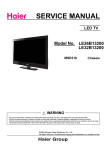
NO Audio & NO Backlight
LED indicator "red" ON
N
Y
Press STANDBY key led
turn green
ckeck the 5V_STANDBY
N
Y
N
ckeck the 5V
N
ckeck all DC
power
ckeck the 12V
N
change Power
board
check ON/OFF signal from
U6
Y
N
Y
Y
check the
U1 part
N
change DC power
IC
Y
upgrade software
change U6
upgrade software
N
Y
Done
Y
change
U1
N
Done
Done
Done
Change U6
Y
change U6 IC
the
N
N
Done
Done
Done
Done
Has video but no audio
N
Check if the volume set to
"0" or if it is mute
Y
ckeck the amplifier
power supply
Y
Y
NO
check audio inut circuit
N
Done
Done
OK
check the bus
circuit
N
change U12
IC
Done
Done
Done
OK
Done
check this
circuit
OK
check mute circuit
and reset circuit
check the
periphery
circuit of U12
Done
Has audio but no video
check the backlight
N
Y
check LVDS line
ckeck the backlight
connector to panel
N
N
Y
ckeck Panel_ON/OFF
circuit
safely connect
the wire
N
change
backlight power
Y
N
Y
check Q1 or
u100 pin205
Done
N
Y
update
software
change Q1
Y
Done
Y
check power
supply circuit
Done
N
change Q45
or U3
N
Y
update software
N
change main
board
Y
Done
check panel
power supply
N
change panel
Y
Done
change or safely connect
the line
Done
Change U6
Done
Done
Done
Done
5
4
Connetor
3
2
1
Inverter controller
5V Standby Power(option) 3A
D
D
+5V_Standby
2
VIN
R1 100K/0402/5%7
+12V_PWR
6
R3 27K/0402/5%/NC
C2
C4
C3 0.1uF/0402/16V
10uF/16V/0805
10uF/16V/0805
CON14/PIN=2.5MM
FB1
U1
AOZ3015PI/SOP8
+12V_PWR
4
C5
1nF/0402/16V/NC
LX
EN
Vo
COMP
FB
VCC
R7
C6
20K/0402/5% 0.1uF/0402/16V
PGND
9
L7
FB2
0R/1206/5%
22uH_3A
FB6
0R/1206/5%/NC
C
D5
1N4148
8
1
R1
R5
C7
51K/0402/1%
C1
0.1uF/0402/16V/NC
0.1uF/0402/16V
470uF/16V/EC3.5
R10
R2
CA3
BL-ON/OFF
+
R159
2
FB8
0R/1206/5%
0R/1206/5%
+12V_NORMAL
3
R17
10K/0402/5%
R16
STANDBY R19
200R/0402/5%
C17
10uF/16V/0805
PWR-ON/OFF
2
3
2
1
+3.3V_Normal +3.3V_Standby
C28
2.2uF/0603/16V
0.1uF/0402/16V
H4
2
9
5
9
5
9
5
4
8
4
8
4
8
4
3
7
3
7
3
7
3
7
3
2
6
2
6
2
6
2
6
2
NC
C18
10uF/16V/0805
L2
22uH_3A
1
GND
NC
4
FB
R20
0.1uF/0402/16V
10uF/16V/0805
R1
R18
4.7K/0402/1%
R2
R22
10K/0402/1% or 8.2K/0402/1%
C13 C19 C14 C15 C16
10uF/16V/0805
10uF/16V/0805
10uF/16V/0805
R25
470R/0402/5%
B
Resistors close to the DC-DC
If chip is 3393,The R2 Value is 10K 1%
If chip is 6306,The R2 Value is 8.2K 1%
H9
5
8
NC
9
8
7
6
NC
C29
0.1uF/0402/16V
2.2uF/0603/16V
1
A
输入加大滤波电容解决插入个别硬盘重启
H5
NC
H6
NC
1
C26 C27
H3
1
H2
9
4
1
3
2
IN
OUT
ADJ
1
SW
C12
1uF/0402/16V
5
NOTICE:
1
H1
AMS1117-3.3
1
U5
NC
+5V_Standby
2.2uF/0603/16V
2.2uF/0603/16V
0.1uF/0402/16V
EN
20R/0402/5%
Vout=0.8V*(1+R1/R2)
Test Point & MARK
1
4
4
3.3V Power
+1.8V_DDR2
R27
100R/0402/5%
BST
100K/0402/5%
C21
10pF/0402/16V
H :Power on
L :Power off
1
C20
0.1uF/0402/16V
R23
100K/0402/5%
U4
0.1uF/0402/16V
C23 C24 C25
IN
增加100UF电解电容,删除C15/C16,改善纹波
R14
4.7K/0402/5%
Q4
3904/SOT-23
AMS1117-Adj
VDDC
6
+3.3V_Standby
2
3
1
R24
22K/0402/5%
IN
OUT
ADJ
R2
C
U3
MP1470
+5V_Normal
5
+5V_Normal C22
BRI_ADJ
+12V_PWR +5V_Standby
FB9
3
C9
0.1uF/0402/16V/NC
U2
4953/SOP8
1
8
S1
D1 7
2
D1 6
3 G1
R12
C10
D2 5
4 S2
100K/0402/5%
G2
D2
0.1uF/0402/16V
R13
C11
100K/0402/5%
1
R15
Q3
0.1uF/0402/16V/NC
22K/0402/5%
3904/SOT-23
1.5V/1.8V Power_Normal
R1
VBL_CTRL
R199
4.7K/0402/5%
Max :1.0A
If POWER BOARD IS 5stb ONLY ,PL NOT PATCH THESE GUY.
220R/0402/5%/470R/0402/5%
R26
1
3904/SOT-23
1.15V Core Power
Standby controller
R21
100K/0402/5%
STANDBY
1
R9
3904/SOT-23 10K/0402/5%
Q2
Vout=0.8V*(1+R1/R2)
STANDBY
STANDBY
R6
10K/0402/5%/NC
Q1
1nF/0402/16V R193
10K/0402/5%/NC
0.1uF/0402/16V/NC
+12V_PWR
B
R8
100R/0402/5%
R11
10K/0402/5% BL-ADJUST
22K/0402/5%
C104
C85
9.1K/0402/1%
+5V_Standby
STANDBY
R4
R200
4.7K/0402/5%
200R/0402/5%
5
+12V_NORMAL
Power Switch
STANDBY
解决耳机冲击声
+5V_Normal
0R/1206/5%
C8
2.2nF/0402/16V
+12V_PWR
MUTE_EAR
3
STANDBY
AGND
FB5
0R/1206/5%/NC
3
FB7 0R/0402/5%/NC
+5V_Normal
2
+5V_Standby
BL-ON/OFF
BL-ADJUST
3
1
2
3
4
5
6
7
8
9
10
11
12
13
14
MUTE_EAR
CN1
A
H7
NC
Vout=1.25V*(R1+R2)/R1
If chip is 3393,The R1 Value is 220R 5% Vout=1.8V
If chip is 6306,The R1 Value is 470R 5% Vout=1.5V
NOTICE:
Title
Size
Custom
5
4
3
2
Date:
MSD3393
Document Number
Rev
1.0
System power
Sunday, July 14, 2013
1
Sheet
1
of
9
5
4
HDMI0-RX0P
HDMI0-RX0N
HDMI0-RX1P
HDMI0-RX1N
HDMI0-RX2P
HDMI0-RX2N
HDMI0-CLKN
HDMI0-CLKP
HDMI0-SCL
HDMI0-SDA
HDMI0-HPDIN
HDMI2-RX0P
HDMI2-RX0N
HDMI2-RX1P
HDMI2-RX1N
HDMI2-RX2P
HDMI2-RX2N
HDMI2-CLKN
HDMI2-CLKP
HDMI2-SCL
HDMI2-SDA
HDMI2-HPDIN
MHL_CABLE-DET
HDMI2-RX0P
HDMI2-RX0N
HDMI2-RX1P
HDMI2-RX1N
HDMI2-RX2P
HDMI2-RX2N
HDMI2-CLKN
HDMI2-CLKP
HDMI2-SCL
HDMI2-SDA
HDMI2-HPDIN
MHL_CABLE-DET
+3.3V_Norm al
HDMI1-CLKN
HDMI1-CLKP
HDMI1-RX0N
HDMI1-RX0P
HDMI1-RX1N
HDMI1-RX1P
HDMI1-RX2N
HDMI1-RX2P
VGA_HSYNC
RGB0_B+
RGB0_G+
RGB0_GRGB0_R+
VGA_VSYNC
HDMI-ARC
HDMI-CEC
HDMI-ARC
HDMI-CEC
PC & YPBPR Interface
VGA-Rin
VGA-Gin
VGA-Bin
+3.3V_Norm al
RGB1_B+
RGB1_SOG
RGB1_G+
RGB1_GRGB1_R+
RGB0_R+
RGB0_GRGB0_G+
RGB0_B+
R28 33R/0402/5% C48
R29 68R/0402/5% C49
R30 33R/0402/5% C50
R31 33R/0402/5% C51
47nF/0402/16V
47nF/0402/16V
47nF/0402/16V
47nF/0402/16V
R32 33R/0402/5% C52
R33 68R/0402/5% C53
R34 33R/0402/5% C54
R35 33R/0402/5% C55
R36 0R/0402/5% C56
47nF/0402/16V RGB1_R+
47nF/0402/16V RGB1_G47nF/0402/16V RGB1_G+
47nF/0402/16V RGB1_B+
1nF/0402/16V RGB1_SOG
VGA_HSYNC
VGA_VSYNC
VGA_HSYNC
VGA_VSYNC
YPbPr_PR
YPbPr_Y
YPbPr_PB
CVBS0+
CVBS_VCOM
CVBS1_OUT
VDDC
+3.3V_AU
LINEIN_R1
LINEIN_L1
AU_VAG
AU_VRM
CVBS IN & OUT
AV1
R38 150R/0402/5% C58
47nF/0402/16V
CVBS0+
R39 180R/0402/5% C60
47nF/0402/16V
CVBS_VCOM
CVBS1_OUT
CVBS1_OUT
VDDC
AVDD5V_MHL
HDMI2-HPDIN
HDMI2-SCL
HDMI2-SDA
MHL_CABLE-DET
HDMI1-SDA
HDMI1-SCL
HDMI0-SDA
HDMI0-SCL
+1.8V_DDR2
VDDC
ARC_DET
HDMI2-RX0P
HDMI2-RX0N
HDMI2-CLKP
HDMI2-CLKN
HDMI0-RX2P
HDMI0-RX2N
HDMI0-RX1P
HDMI0-RX1N
HDMI0-RX0P
HDMI0-RX0N
HDMI0-CLKP
HDMI0-CLKN
MSD3393LU
C32
C33
0.1uF/0402/16V
0.1uF/0402/16V
MSD3393LU
+3.3V_Norm al
KEY1-SAR1
KEY0-SAR0
+3.3V_Norm al
USB1_D+
USB1_DUSB2_D+
USB2_DSys tem -RST
PANEL_ON/OFF
IR-in
HDMI-CEC
UART-RX
UART-TX
HDMI-ARC
SPI_SCK
SPI_CSN
SPI_SDI
SPI_SDO
BRI_ADJ
VBL_CTRL
HDMI1-HPDIN
HDMI0-HPDIN
R7_RXO0R6_RXO0+
R5_RXO1R4_RXO1+
R3_RXO2R2_RXO2+
+3.3V_Norm al
G7_RXO3G6_RXO3+
G3_RXE0G2_RXE0+
G1_RXE1G0_RXE1+
B7_RXE2B6_RXE2+
C35
C36
2.2uF/0603/16V
0.1uF/0402/16V
C38
0.1uF/0402/16V
2.2uF/0603/16V
2.2uF/0603/16V
LINEIN_L4
LINEIN_R4
+3.3V_PLL
L4
0R/0603/5%
C37
0.1uF/0402/16V
C39
0.1uF/0402/16V
3.3V
+3.3V_Norm al
L5
C40
2.2uF/0603/16V
+3.3V_ADC
D
0R/0603/5%
0.1uF/0402/16V
0.1uF/0402/16V
C46
C41
C42
C43
C44
C45
0.1uF/0402/16V
0.1uF/0402/16V
0.1uF/0402/16V 2.2uF/0603/16V
C47
0.1uF/0402/16V
Audio Line Out
LINE0OUT_L
HEAT
AV_AUOUTL1
C165
SINK
R37
200K/0402/5%
1nF/0402/16V
AV_AUOUTR1
C57
R40
200K/0402/5%
1nF/0402/16V
H8
1
2
LINEOUT_APML
C62
R41
200K/0402/5%
1nF/0402/16V
LINE3OUT_R
CON2/NC
LINEOUT_APMR
C66
R42
200K/0402/5%
1nF/0402/16V
DIF IN
Close to Mstar IC
C67 VIFP
IFP
+3.3V_Norm al
0R/0603/5%
LINE0OUT_R
TUNER_SDA
TUNER_SCL
MHL_VBUS-EN
AMP-MUTE
PWR-ON/OFF
SPDIF_OUT
B2_RXE3+
B3_RXE3B4_RXEC+
B5_RXEC-
C64
C65
XTALI
XTALO
AV1-Lin
AV1-Rin
LINEIN_L4
LINEIN_R4
LINE3OUT_L
LINE3OUT_R
LINE0OUT_L
LINE0OUT_R
IFAGC
VIFP
VIFM
LINEIN_L1
LINEIN_R1
3.3V MPLL
+3.3V_AU
L3
102
101
100
99
98
97
96
95
94
93
92
91
90
89
88
87
86
85
84
83
82
81
80
79
78
77
76
75
74
73
72
71
70
69
68
67
66
65
VDDC
2.2uF/0603/16V
2.2uF/0603/16V
+1.8V_DDR2
+3.3V_Normal
C61
C63
C34
0.1uF/0402/16V
3.3V audio
+1.8V_DDR2
SAR1
SAR0
AVDD_MOD
DP_P1
DM_P1
DP_P0
DM_P0
RESET
INT/GPIO64
IRIN
CEC
TEST
DDCA_CK
DDCA_DA
ARC
SPI_CK
SPI_CZ
SPI_DI
SPI_DO
PWM0
PWM1
HOTPLUG_A
HOTPLUG_C/D
LDE/LVB0M
LCK/LVB0P
LVB1M
LVB1P
LVB2M
LVB2P
AVDD_MOD
LVB3M
LVB3P
LVA0M
LVA0P
LVA1M
LVA1P
LVA2M
LVA2P
LINE3OUT_L
VGA-Lin_AU
VGA-Rin_AU
+3.3V_PLL
+3.3V_ADC
AV1-Lin
AV1-Rin
1
132
131
130
129
128
127
126
125
124
123
122
121
120
119
118
117
116
115
114
113
112
111
110
109
108
107
106
105
104
103
RX1N_B
RX1P_B
RX2N_B
RX2P_B
AVDD_MOD
RXCN_A
RXCP_A
RX0N_A
RX0P_A
RX1N_A
RX1P_A
RX2N_A
RX2P_A
HSYNC0
BIN0P
GIN0P
GIN0M
RIN0P
VSYNC0
AVDD3P3_ADC
BIN1P
SOGIN1
GIN1P
GIN1M
RIN1P
VSYNC1
CVBS1
CVBS0
VCOM
CVBS_OUT1
VDDC
AVDD_AU33
AUR0
AUL0
AUR1
AUL1
VAG
VRM
AUDIO IN
VGA-Lin_AU
VGA-Rin_AU
C31
0.1uF/0402/16V
DDR2 1.8V
E-PAD
Test
MARK
MARK
RX0P_B
RX0N_B
RXCP_B
RXCN_B
RX2P_D
RX2N_D
RX1P_D
RX1N_D
RX0P_D
RX0N_D
RXCP_D
RXCN_D
VDDC/AVDDL_DVI
GND_EFUSE
AVDD_5V
HOTPLUG_B
DDCDB_CL
DDCDB_DA
MHL_DET
DDCDA_DA
DDCDA_CL
DDCDC_DA
DDCDC_CL
VDDIO_DATA
VDDC/DVDD_DDR_DATA
SAR2
U6
1
2
3
4
5
6
7
8
9
10
11
12
13
14
15
16
17
18
19
20
21
22
23
24
25
26
27
28
29
30
31
32
33
34
35
36
37
38
HDMI2-RX1N
HDMI2-RX1P
HDMI2-RX2N
HDMI2-RX2P
C30
2.2uF/0603/16V
AUL4
AUR4
AUOUTL3
AUOUTR3
AUOUTL0
AUOUTR0
IFAGC
VIFP
VIFM
AVDD3P3_DADC
AVDD3P3_DMPLL
XIN
Xout
AVDD_MOD
VDDIO_CMD
VDDC/DVDD_DDR_CMD
GPIO0/GPIO44
GPIO1/GPIO45
GPIO2/GPIO46
GPIO3/GPIO47
GPIO4/GPIO48
GPIO5/GPIO49
LVA3P
LVA3M
LVACKP
LVACKM
0.1uF/0402/16V
C68 VIFM
IFN
0.1uF/0402/16V
+3.3V_TU
+3.3V_Standby
1
XTAL
2
C75
2.2uF/0603/16V
Q5
3906/SOT-23
R52
1K/0402/5%
3
R50
1
10K/0402/5%
C
C78
2.2uF/0603/16V
XTALO
CHIP_CONFIG
R51
0R/0402/5%
Sys tem -RST
R54
C77
100K/0402/5% 1nF/0402/16V
XTALI
C76
33pF/0402/16V
{IPAD_PWM1, PAD_PWM0}
B51_NO_EJ 4'h00
Y1
3
R53
1M/0402/5%
24.000MHz
C79
33pF/0402/16V
PWM1
R57
4.7K/0402/5%
PWM0
R58
4.7K/0402/5%
PWR-ON/OFF
BRI_ADJ
VBL_CTRL
MHL_VBUS-EN
AMP-MUTE
PANEL_ON/OFF
ARC_DET
TUNER_SCL
TUNER_SDA
TUNER_SCL
TUNER_SDA
R7_RXO0R6_RXO0+
R5_RXO1R4_RXO1+
R3_RXO2R2_RXO2+
G7_RXO3G6_RXO3+
FLASH
DEBUG
+5V_Standby
+3.3V_Standby
MUST pull high to 5VSTB
R64 R65
ISP AND VGA EDID
UART-TX R66
UART-RX R67
4.7K/0402/5%
4.7K/0402/5%
100R/0402/5%
UART_TX
100R/0402/5%
UART_RX
C81
SPI_SCK
SPI_SDI
+3.3V_Standby
U7
MX25L3205
8
7
6
5
VDD
HOLD#
SCK
SI
CE#
SO
WP#
VSS
1
2
3
4
SPI_CSN
SPI_SDO
#F_WP
R63
10K/0402/5%
G3_RXE0G2_RXE0+
G1_RXE1G0_RXE1+
B7_RXE2B6_RXE2+
B5_RXECB4_RXEC+
B3_RXE3B2_RXE3+
KEY1-in
0.1uF/0402/16V
IR_in
R48
1K/0402/5%
C73
D51
ESD/NC
LED_R
KEY1-SAR1
D52
ESD/NC
0.1uF/0402/16V
LED_G
+3.3V_Standby
+3.3V_Norm al
+3.3V_Standby
R55
2K/0402/5%
+5V_Standby
G7_RXO3G6_RXO3+
B7_RXE2B6_RXE2+
B5_RXECB4_RXEC+
B3_RXE3B2_RXE3+
KEY0-in
C
R7_RXO0R6_RXO0+
R5_RXO1R4_RXO1+
R3_RXO2R2_RXO2+
G3_RXE0G2_RXE0+
G1_RXE1G0_RXE1+
R45
8.2K/0402/5%
8.2K/0402/5%
R47
KEY0-SAR0
1K/0402/5%
C74
KEY0-in
KEY1-in
2
22nF/0402/16V
+3.3V_Standby
R44
+5V_Standby
1
2
3
4
5
6
7
8
9
10
11
12
PWR-ON/OFF
PWM0
PWM1
MHL_VBUS-EN
AMP-MUTE
PANEL_ON/OFF
ARC_DET
1
D1
BAV99
R49
100K/0402/5%
CN3
CON20W-J20-12
KEY1-SAR1
Q6
R60
10K/0402/5%
IR_in
R62
100R/0402/5%
C80
33pF/0402/16V
STANDBY
IR-in
D54
ESD/NC
R61
4.7K/0402/5%
Q7
1
R56
4.7K/0402/5%
LED_G
3
IFAGC-T
0R/0402/5% C72
1
LED_R R59
4.7K/0402/5%
2
R46
3
+5V_Standby
KEY0-SAR0
2
IFAGC
IR-in
1
Close to Mstar IC
R43
10K/0402/5%
3
C71
3904/SOT-23
3904/SOT-23
2
C70
0R/0603/5%
RESET
C69
2.2uF/0603/16V
0.1uF/0402/16V
2.2uF/0603/16V
L6
2
SPDIF_OUT
1
USB1_DUSB1_D+
USB1_DUSB1_D+
IR&KEYB
AU_VRM
AU_VAG
USB2_DUSB2_D+
USB2_DUSB2_D+
SPDIF_OUT
D53
ESD/NC
1
USB & SPDIF_OUT
2
D
1
HDMI1-RX0P
HDMI1-RX0N
HDMI1-RX1P
HDMI1-RX1N
HDMI1-RX2P
HDMI1-RX2N
HDMI1-CLKN
HDMI1-CLKP
HDMI1-SCL
HDMI1-SDA
HDMI1-HPDIN
HDMI1-RX0P
HDMI1-RX0N
HDMI1-RX1P
HDMI1-RX1N
HDMI1-RX2P
HDMI1-RX2N
HDMI1-CLKN
HDMI1-CLKP
HDMI1-SCL
HDMI1-SDA
HDMI1-HPDIN
2
VDDC
TP4
39
40
41
42
43
44
45
46
47
48
49
50
51
52
53
54
55
56
57
58
59
60
61
62
63
64
HDMI0-RX0P
HDMI0-RX0N
HDMI0-RX1P
HDMI0-RX1N
HDMI0-RX2P
HDMI0-RX2N
HDMI0-CLKN
HDMI0-CLKP
HDMI0-SCL
HDMI0-SDA
HDMI0-HPDIN
3
VDDC 1.15V
HDMI Interface
Standby :H :Power on Green Led
L :Power off Red Led
0.1uF/0402/16V
B
B
A
A
Title
Size
E
5
4
3
2
1
Date:
MSD3393
Docum ent Num ber
Rev
1.0
MAIN CHIP
Saturday, June 08, 2013
Sheet
2
of
9
5
4
3
2
1
LVDS CONNECTOR ( 1 DIP + 2 SMT OPTIONAL )
HI CONNECTOR
Power for panel
D
D
VCC-Panel
FB3
0R/1206/5%/NC
+5V_Normal
TUNER_SDA
M_SDA
CN2
0.1uF/0402/16V1
3
5
7
9
11
B2_RXE3+
13
B4_RXEC+
15
B6_RXE2+
17
G0_RXE1+
19
G2_RXE0+
21
23
25
DCR-IN
27
29
31
G6_RXO3+
33
R0_RXOC+
35
R2_RXO2+
37
R4_RXO1+
39
R6_RXO0+
41
43
45
R481 NC/100R/0402/5%
FB4
VCC VCC
VCC VCC
GND GND
GND GND
A4P A4M
A3P A3M
ACKPACKM
A2P A2M
A1P A1M
A0P A0M
GND GND
IO MODE
PWMDCRO
GND GND
B4P B4M
B3P B3M
BCKPBCKM
B2P B2M
B1P B1M
B0P B0M
GND GND
SDA SCL
GND GND
2
4
6
8
10
12
14
16
18
20
22
24
26
28
30
32
34
36
38
40
42
44
46
VPANEL_IN
VCC-Panel
0R/1206/5%
+12V_NORMAL
C82
R68
0.1uF/0402/16V/NC
100K/0402/5%
+3.3V_Normal
B3_RXE3B5_RXECB7_RXE2G1_RXE1G3_RXE0SG_SYNC
8_10BIT_SEL
DCR-OUT
R73
10K/0402/5%NC
3
100uF/16V
C
C103
+
PANEL_ON/OFF
R70
0/NC
G7_RXO3R1_RXOCR3_RXO2R5_RXO1R7_RXO0-
R72
NC/0
PANEL_ON/OFF
1
R71
4.7K/0402/5%
R2
4.7K/0402/5%
3904/SOT-23
C
R74
DCR-OUT
100R/0402/5%/NC
R75
DCR-IN
100R/0402/5%/NC
R7_RXO0R6_RXO0+
R5_RXO1R4_RXO1+
R3_RXO2R2_RXO2+
G7_RXO3G6_RXO3+
G2_RXE0+
G1_RXE1G0_RXE1+
B7_RXE2B6_RXE2+
B5_RXECB4_RXEC+
B3_RXE3B2_RXE3+
R1_RXOCR0_RXOC+
G3_RXE0G2_RXE0+
G1_RXE1G0_RXE1+
B7_RXE2B6_RXE2+
B5_RXECB4_RXEC+
B3_RXE3B2_RXE3+
B5_RXECB4_RXEC+
B
3D_SOCKET
2
1
2
3
+5V_Normal
NC/100
R168
SG_SYNC
D347
NC
1
CN35
CON03
S
S
S
G
9435/SOP8
5
D 6
D 7
D 8
D
Q8
AO3401A/SOT-23/NC
1uF/0402/16V/NC
C84
0.1uF/0402/16V/NC
R69
100K/0402/5%
R7_RXO0R6_RXO0+
R5_RXO1R4_RXO1+
R3_RXO2R2_RXO2+
G7_RXO3G6_RXO3+
NC/CON22X2_2.0
B
U8
Net to other page
G3_RXE0-
M_SCL TUNER_SCL
R488 NC/100R/0402/5%
BRI_ADJ
Q9
C83
1
2
3
4
2
CA6
A
A
Title
Size
B
5
4
3
2
Date:
MSD3393
Document Number
Rev
1.0
LVDS Interface
Saturday, June 08, 2013
Sheet
1
3
of
9
5
4
3
2
1
VIDEO OUT
C102
+5V_Normal
3906/SOT23
Q17
P1
2
4
6
R76
1
10K/0402/5%
R77
3
10K/0402/5%
R79
AV1
C86
12K/0402/5%
220pF/0402/16V/NC 220pF/0402/16V/NC
C87
5
R209
RCA-3P
AV1-Rin
AVOUT-V R155
75R/0402/5%
R78
0.1uF/0402/16V
470R/0402/5% R208
20K/0402/5%
D
3
AV IN
Q18
3904/SOT23
R206
75R/0402/5%
AV1-Lin
2
D
1
C97
R207
12K/0402/5%
CVBS1_OUT
10uF/0603/16V
R154
75R/0402/5%
R80
12K/0402/5%
TP1
75R/0402/5%
FOR ATV/AV DEBUG
C
C
SPDIF OUT
CN42
YPBPR
1
P2
PHONEJACK STEREO 180D
1
2
YPbPr_PR
3
YPbPr_PB
4
YPbPr_Y
B
RCA1_180D
2SPDIF_O
3
R81
R82
330R/0402/5%
SPDIF_OUT
C88
100R/0402/5%
33pF/0402/16V
Closed to IC
B
Close to Mstar IC
R83
R84
R85
75R/0402/5%
75R/0402/5%
75R/0402/5%
A
A
Title
Size
B
5
4
3
2
Date:
MSD3393
Document Number
Rev
1.0
Video Interface
Saturday, June 08, 2013
Sheet
1
4
of
9
5
4
3
VGA
2
1
VGA AUDIO IN
16
P4
D
D
11
1
6
2
7
3
8
4
9
5
10
12
13
14
17
15
VGA-Rin
VGA-Gin
VGA-Bin
1
2
3
VGA/15 PIN
DDC_SCL_D
DDC_SDA_D
C
R93
10K/0402/5%
R92
10K/0402/5%
PHONEJACK STEREO 90D
100R/0402/5%
100R/0402/5%
P5
UART_RX
UART_TX
R90
R91
R86
10K/0402/5% VGA-Lin_AU
VGA-Lin_AU
R87
10K/0402/5% VGA-Rin_AU
VGA-Rin_AU
R88
12K/0402/5%
4
R89
12K/0402/5%
C89
220p/0402/16V
C90
220p/0402/16V
C
VGA_VSYNC
VGA_HSYNC
B
B
VGA-Bin
VGA-Gin
VGA-Rin
VGA-Bin
VGA-Gin
VGA-Rin
R94
R95
R96
75R/0402/5%
75R/0402/5%
75R/0402/5%
Close to Mstar IC
A
A
Title
Size
MSD3393
Document Number
5
4
3
Date:
Rev
1.0
VGA Interface
A
Saturday, June 08, 2013
2
Sheet
5
1
of
9
5
4
3
USB INTERFACE
D
2
1
USB POWER
D
P6
USB_A
5
6
5
6
1
2
3
4
1
2
3
4
USB1_D1-_in
USB1_D1+_in
+5V_USB0
R97
R98
5.1/0402/5%
5.1/0402/5%
USB1_DUSB1_D+
USB1_DUSB1_D+
5V_USB
D2
+5V_Normal
+5V_USB0
5V_USB
C92
C91
2.2uF/0603/16V
0.1uF/0402/16V
C
USB_A
5
5
6
6
1
2
3
4
P7
1
2
3
4
USB2_D1-_in
USB2_D1+_in
+5V_USB0
Note:电容靠近USB(CN600)端子,提供usb读写稳定性
R99
R100
5.1R
5.1R
USB2_DUSB2_D+
+5V_USB0
USB2_DUSB2_D+
C
5V_USB
C94
C93
2.2uF/0603/16V
0.1uF/0402/16V
Note:5.1R电阻靠近端子,减小ESD.
Note:电容靠近USB(CN601)端子,提供usb读写稳定性
USB ESD分布电容要求<2pF
B
B
A
A
Title
Size
MSD3393
Document Number
5
4
3
Date:
Rev
1.0
USB Interface
A
Saturday, June 08, 2013
2
Sheet
6
1
of
9
5
+5V
CEC/DDC GND
DDC SCL
DDC SDA
CEC
HPD
靠近端子放置
18
17
15
16
13
19
HDMI3/5V
HDMI3-DDC-SCL
HDMI3-DDC-SDA
CEC
HDMI3-HPD
2
5
8
11
Dat2 shield
Dat1 shield
Dat0 shield
clk shield
R101
HDMI3-RX2P
5.1R/0402/5%
HDMI3_RX2N
HDMI3_RX1P
R103
R107
HDMI3-RX2N
5.1R/0402/5%
HDMI3-RX1P
5.1R/0402/5%
HDMI3_RX1N
HDMI3_RX0P
R108
R109
HDMI3-RX1N
5.1R/0402/5%
5.1R/0402/5%
HDMI3-RX0P
HDMI3_RX0N
HDMI3_CLKP
R111
R113
HDMI3-RX0N
5.1R/0402/5%
5.1R/0402/5%
HDMI3-CLKP
HDMI3_CLKN
R115
5.1R/0402/5%
HDMI3-CLKN
R102
HDMI0-RX2P
R104
HDMI0-RX2N
HDMI0-RX1P
HDMI0-RX1N
HDMI0-RX0P
HDMI0-RX0N
HDMI0-CLKP
1
R106
R105
10K/0402/5%
HDMI3-DDC-SCL
HDMI3-DDC-SDA
2
HDMI3/5V
HDMI3/5V
HDMI3_RX2P
HDMI3-HPD
10K/0402/5%
R110
R112
1K/0402/5%
3
20
21
22
23
GND
GND
GND
GND
3
33R/0402/5%
HDMI0-SCL
33R/0402/5%
HDMI0-SDA
Q10
1R114
10K/0402/5%
HDMI0-HPDIN
4.7K/0402/5%
HDMI0-HPDIN
3904/SOT-23
2
P8
4
HDMI0-CLKN
D
D
7
9
4
6
1
3
10
12
14
DAT0+
DAT0DAT1+
DAT1DAT2+
DAT2clk+
clkARC1
HDMI3_RX0P
HDMI3_RX0N
HDMI3_RX1P
HDMI3_RX1N
HDMI3_RX2P
HDMI3_RX2N
HDMI3_CLKP
HDMI3_CLKN
HDMI_ARC
HDMI3
HDMI
P9
DAT0+
DAT0DAT1+
DAT1DAT2+
DAT2clk+
clkARC1
C
18
17
15
16
13
19
HDMI1/5V
HDMI1-DDC-SCL
HDMI1-DDC-SDA
CEC
HDMI1-HPD
2
5
8
11
7
9
4
6
1
3
10
12
14
HDMI1_RX2P
R116
HDMI1-RX2P
5.1R/0402/5%
HDMI1_RX2N
HDMI1_RX1P
R117
R119
HDMI1-RX2N
5.1R/0402/5%
HDMI1-RX1P
5.1R/0402/5%
HDMI1_RX1N
HDMI1_RX0P
R121
R123
HDMI1-RX1N
5.1R/0402/5%
5.1R/0402/5%
HDMI1-RX0P
HDMI1_RX0N
HDMI1_CLKP
R125
R126
HDMI1-RX0N
5.1R/0402/5%
5.1R/0402/5%
HDMI1-CLKP
HDMI1_CLKN
R130
5.1R/0402/5%
HDMI1-CLKN
HDMI1/5V
HDMI1-RX2P
R118
HDMI1-RX2N
HDMI1-RX1P
R124
HDMI1-RX1N
HDMI1-RX0P
R122
10K/0402/5%
10K/0402/5%
HDMI1-RX0N
HDMI1-CLKP
HDMI1-DDC-SCL
HDMI1-DDC-SDA
HDMI1-HPD
R127
R129
33R/0402/5%
HDMI1-SCL
33R/0402/5%
HDMI1-SDA
HDMI1-CLKN
R120
1K/0402/5%
3
+5V
CEC/DDC GND
DDC SCL
DDC SDA
CEC
HPD
HDMI1/5V
Q11
1R128
10K/0402/5%
4.7K/0402/5%/NC
HDMI1-HPDIN
HDMI1-HPDIN
3904/SOT-23
2
GND
GND
GND
GND
Dat2 shield
Dat1 shield
Dat0 shield
clk shield
靠近端子放置
20
21
22
23
HDMI1_RX0P
HDMI1_RX0N
HDMI1_RX1P
HDMI1_RX1N
HDMI1_RX2P
HDMI1_RX2N
HDMI1_CLKP
HDMI1_CLKN
C
HDMI1
HDMI
P10
20
21
22
23
GND
GND
GND
GND
18
17
15
16
13
19
+5V
CEC/DDC GND
DDC SCL
DDC SDA
CEC
HPD
HDMI2/5V
HDMI2-DDC-SCL
HDMI2-DDC-SDA
CEC
HDMI2-HPD
2
5
8
11
Dat2 shield
Dat1 shield
Dat0 shield
clk shield
MHL_CD_SENSE
MHL,上拉电压必须为此,SCL上拉电阻47K
AVDD5V_CD
7
9
4
6
1
3
10
12
14
DAT0+
DAT0DAT1+
DAT1DAT2+
DAT2clk+
clkARC1
靠近端子放置
HDMI2_RX0P
HDMI2_RX0N
HDMI2_RX1P
HDMI2_RX1N
HDMI2_RX2P
HDMI2_RX2N
HDMI2_CLKP
HDMI2_CLKN
HDMI2_RX2P
R131
0R/0402/5%
HDMI2-RX2P
HDMI2_RX2N
HDMI2_RX1P
R132
R133
HDMI2-RX2N
0R/0402/5%
0R/0402/5%
HDMI2-RX1P
HDMI2_RX1N
HDMI2_RX0P
R134
R137
0R/0402/5%
HDMI2-RX1N
HDMI2-RX0P
0R/0402/5%
HDMI2_RX0N
HDMI2_CLKP
R139
R141
0R/0402/5%
HDMI2-RX0N
HDMI2-CLKP
0R/0402/5%
HDMI2_CLKN
R143
HDMI2-CLKN
0R/0402/5%
HDMI2-RX2P
HDMI2-RX2N
HDMI2-RX1P
R135 R136
47K/0402/5%
HDMI2-RX1N
HDMI2-RX0P
10K/0402/5%
HDMI2-DDC-SCL
HDMI2-DDC-SDA
HDMI2-RX0N
HDMI2-CLKP
R140
R142
33R/0402/5%
HDMI2-SCL
33R/0402/5%
HDMI2-SDA
HDMI2-HPD
不需要MHL功能,R709/R710的上拉可为HDMI2/5V,电阻值为10K
HDMI2-HPDIN
33R/0402/5%
HDMI2-HPDIN
IC内置hotplug电路
B
HDMI
CEC & ARC
CEC
HDMI3/5V
MHL
HDMI-ARC
C95
2.2uF/0603/16V
R144
HDMI2/5V
200R/0402/5%
HDMI-CEC
R148
根据ARC所放的HDMI定
HDMI-ARC
+5V_Standby
HDMI-CEC
4.7K/0402/5%
ARC_DET
R150
10K/0402/5%
R145
2
AVDD5V_CD
0R/0402/5%
+5V_Normal
HDMI2/5V
100R/0402/5%
MHL_CABLE-DET
R149
C96
300K/0402/5%
47nF/0402/16V
3
1
R146
MHL_CD_SENSE
AVDD5V_MHL
D3
BAT54C/SOT23/NC
R152
10R/0402/5%
R151
10K/0402/5% 4
MHL_VBUS-EN
更新为此
HDMI2/5V
R147 10K/0402/5%/NC
QA1
5
3
VIN
/OC
/EN
GND
HDMI_ARC
VOUT
1
AP2181DWG-7
2
B
R138
HDMI2-CLKN
电阻必须300K
平台不需要MHL功能,此部分电路不需要
HDMI2 With MHL
A
A
Title
Size
Document Number
D
5
4
3
2
Date:
1
MSD3393
Rev
1.0
HDMI Interface
Saturday, June 08, 2013
Sheet
7
of
9
5
4
3
2
1
Silicon TUNER
+3.3V_TU
+3.3V_TU
+3.3V_TU
D
C99
26
C183
180pF/0402/16V
27
28
C
29
15
XOUT
LDO_ADJ
Si2158
ADDR
+3.3V
U10
RSTB
DLIF_N
AGC1
+1.8V
GND_EPAD
2
3
3
17
XTAL_I/RCLK
19
18
XTAL_O
20
GND
DLIF_P
+1.8V_TU
13
R203
100R/0402/5%
IF-IN+
12
R204
100R/0402/5%
IF-IN-
11
10
+3.3V_TU
9
8
+1.8V_TU
C
+1.8V_TU
R202
0R/0402/5%
C171
R201
0R/0402/5%
1nF/0402/16V
1nF/0402/16V
C1
SCL-T
C170
IF_AGC
C166
C167 C168
1nF/0402/16V
1nF/0402/16V
1nF/0402/16V
+3.3V_TU
+3.3V_TU
+3.3V
ALIF_N
RF_SHIELD
1
AGND
RF_IN
14
GND
25
+1.8V
ALIF_P
+3.3V
L29
L25 270nH/0603/ 5%
270nH/0603/ 5%
C182
2.2uF/0402/16V
7
180nH/0603/ 5%
RF_IP
SDA
L23
6
L22
270nH/0402/ 5%
Y2
24.000MHz
5
R158
0R/0402/5%
RF_REF
Q16
3906/SOT-23+1.8V_TU
SDA-T
R157
0R/0402/5%
1.2nF/0402/16V
22
C174
L28
L26
270nH/0603/ 5% 270nH/0603/ 5%
L24
C175
180pF/0402/16V 23
100pF/0402/16V
0R/0402/5%
C176
180pF/0402/16V 24
SCL
16
17
47pF/0402/16V
C172
C173
AGC2
AGND
GPIO2
2
3
AGND
C101
120pF/0402/50V
0.1uF/0402/16V
12pF/0402/16V/NC
1
C181
16
68pF/0402/16V
1nF/0402/16V
21
PE42750DS/NC
U9
12pF/0402/16V/NC
close 20pin C180
C179
68pF/0402/16V
C169
+3.3V
VDD 12
C1 11
10
C2
AGND
C178
C177
GPIO1
1
R205
3.3R/0402/1%
24 MHz /ESR< 120 , CL=8pF
2158 FOR LOW SINGER WATER WAVE
2157 CAN CANCLE
2
C100
120pF/0402/50V/NC
0.1uF/0402/16V/NC
AGND
GND 9
RF2 8
GND 7
C1
CON43RCA1_6
3
4
5
6
7
AGND
1
GND
2 RF1
3 GND
4
GND
5 RFC
6 GND
AGND
4
47nF/0402/16V/NC
D
L27
600R/0402/500mA
R153
100R/0402/5%/NC
C98
DIF IN&OUT
AGC RC Filter &I2C
TUNER POWER
B
+3.3V_Normal
10K/0402/5% R160
IF-IN+
C132 L12 0R/0603/5%
20pF/0402/16V/NC
510R/0402/5%/NC
C126
L11 0R/0603/5%
C125
100pF/0402/16V
R165
C133
IFAGC-T
100R/0402/5%
OUT
OUT
4
IN
C127
IF_AGC
+3.3V_TU
+5V_Normal
20pF/0402/16V/NC
Close MSD IC
VIFP
IFP
0.1uF/0402/16V
1
3
100R/0402/5%
TUNER_SCL
C124
R164
10uF/0805/16V
IFAGC-T
0.1uF/0402/16V
C130
C131
10uF/0805/16V
C123
33pF/0402/16V/NC
100R/0402/5%
TUNER_SDA
R163
10uF/0805/16V
L10 0R/0603/5%
C122
56pF/0402/16V
R162
SCL-T
C129
0R/0603/5%
VIFM
IFN
0.1uF/0402/16V
0.1uF/0402/16V
L9
BPF_IN
C121
C128
IF-IN-
SDA-T
2
10K/0402/5% R161
C120
100pF/0402/16V
ADJ
U11
ASM1117-3.3_1A
0.1uF/0402/16V
B
Close Tuner
A
A
Title
Size
C
5
4
3
2
Date:
Document Number
MSD3393
Rev
1.0
Tuner
Thursday, June 20, 2013
1
Sheet
8
of
9
5
4
3
2
1
L13
TPA3110
AU. AMP
VCC-AMP
D
+12V_NORMAL
0.1uF/0402/16V
C164
150R/0402/5%
C163
L1
C138
MUTE_AMP
R171
2.2nF/0402/50V/NC
R169
1uF/0603/16V
0.1uF/0402/16V
R172 1K/0402/5%
1
2
47K/0402/5%
3
L1
R175
4
150R/0402/5%
6
C156
R185
2.2nF/0402/50V/NC 47K/0402/5%
C
R186
R190
R184
C154
R187
8
4.7K/0402/5%
1uF/0603/16V
22K/0402/5%
10R/0402/5%
22K/0402/5%/NCR179
R1
0.1uF/0402/16V
22K/0402/5%/NC
C136
150R/0402/5%
22K/0402/5% R183
7
R189
9
C155
C157 R191
3K/0402/5% 1uF/0603/16V
1uF/0603/16V
C159
10
11
12
220nF/0402/16V 13
R1
R192
150R/0402/5%
+12V_NORMAL
14
PVCCL
SD
PVCCL
FAULT
PVCCL
LINP
BSPL
LINN
OUTPL
GAIN0
PGND
GAIN1
OUTNL
AVCC
BSNL
AGND
BSNR
GVDD
OUTNR
PLMIT
PGND
RINN
OUTPR
RINP
BSPR
NC
PBTL
29
VCC-AMP
1
C137
220nF/0805/50V
L15 0R/1206/5%
PVCCR
PVCCR
28
C143
220nF/0603/50V
27
26
1
L16
22uH/2.7A/NC
2
L17 0R/1206/5%
25
+5V_Normal
CON2
R198
100K
1
2
C145
2X2.0MM
220nF/0805/50V
PH-Lout
24
C146
220nF/0603/50V
23
22
C153
220nF/0603/50V
20
L19 0R/1206/5%
19
18
C158
17
220nF/0603/50V
22uH/2.7A/NC
2
1
L20
22uH/2.7A/NC
2
L21 0R/1206/5%
AV_AUOUTL1
C311
2.2uF
C152
220nF/0805/50V
CON3
2
1
R211
100
C59
2.2uF
2
3
4
OUT1
VCC
MUTE
OUT2
IN1
GND
BH3544
BIAS
IN2
8
7
CA25
100uF/16V
PH-Rout
6
5
CA18
47uF/16V
R210
+
+
100
C312
2.2uF
AV_AUOUTR1
AV_AUOUTR1
CA19
47uF/16V
C
2X2.5MM
C160
220nF/0805/50V
16
C161
AV_AUOUTL1
D198
1N4148
U13
1
100uF/16V
MUTE_EAR
L18
1
21
15
CA24
+
C144 220nF/0402/10V 5
LINEOUT_APMR
C135
R167
100K/0402/5%
100K/0402/5% U12
GVDD
R166
LINEOUT_APML
L14
22uH/2.7A/NC
2
+
D
0R/1206/5%
+12V_NORMAL
+ CA1
0.1uF/0402/16V
100uF/35V/ECS-5M
VCC-AMP
IC-TPA3121D2_0
P3
PHONEJACK STEREO 180D
+5V_Normal
1
R285
NC\0
B
R283
470
D6
D4
100K
PWD_MT
Q22
MMBT3906
MUTE_EAR
R286 10K
1N4148
+5V_Standby
+ CA55
100uF/16V
B
1
Q24
3904
2
R246
PH-Rout
3
0
PH-Lout
3
4
1N4148
R247
2
MUTE_AMP
R248
470
R284
0\NC
R293
47K
4.7K/NC
R310
MUTE_AMP
D7
BAV70
3
2 AMP-MUTE
R299
1
Q25
3904
2
H: MUTE, L: UN-MUTE
R287 10K
47K
A
A
Title
Size
Custom
Date:
5
4
3
2
Document Number
MSD3393
Rev
1.0
Amplifier
Thursday, June 20, 2013
1
Sheet
9
of
9
5
4
3
2
1
LB2
RB17
1M/1206
DB12
DB13
+
CB37
102/2KV
C39
68UF/450V
RB19
1M/1206
TH1
DB10
CY4
222/400VAC
RB3
200K/2W
DB11
CB1
102/2KV
5R4A
D
RB29
1M/1206
RB69
471/1206
RB15
RB21
RB20
QB1
0765
DB9
LL4148
RB9
22R/0805
RB10
33R/1206
6
QB4
15N10
DB3
MBR20150C
1
11
2M/1206
2M/1206
1
2
3
GND GATE
FB
VDD
NC
CS
6
5
4
RB12
RB52
68R/0805
ZDB2(NC)
DRV
7
RB60
RB42
0R47/1206
0R47/1206
RB48
10K/0805
CB26
474/50V
4R7/1206
1
RB16
DB14
BA158(DO-35)
2
+
470K/0805
CB12
104
ZDB1
24V
4
CB29
102
10
CB41
4.7UF 50V
+12VA
LB1
0.7uH
2
LFB1
12.9*7.5*5.3
2
RB53
10K/0805
RB8
1
2
RB49
100K/0805
3V3
104
1
3
ZDB7
6V2
2
1
CB15
RB61
0R47/1206
FB
0.39R/2W
RB1
CB13
221
470K/0805
224/275VAC
CB10
100UF/50V
4
JB2
1K/1206
RB14
CX2
CB2
224/100V
ISENSE
ZDB6
15V
1
2M/1206
+
CB7
1000UF35V
2
2M/1206
RB47
200K/0805
1
+
UB2
DB6
SB3100
LED+
3
RB14
DB5
SB3100
3
CY2
471/400VAC
12
2
RB44
1M/1206
4
CY1
471/400VAC
LB3
150uH
F2
FUSE T1A 250V
1
RB64
471/1206
RB63
471/1206
3
CB9
102
+24VA
DB1
BA159
RB68
471/1206
2
RB65
471/1206
1
LFB3
ET28D
T1
EFD34
RB43
1M/1206
G1
+12V
DB4
MBR20100C
C
1
RB7
RB6
1M/1206
1M/1206
1M/1206
CB4
ZDB9(NC)
CB5
1000UF/25V
3V3
1000uF/25V
CN7
11PIN
+
+
2
RB4
RB5
+12VA
+24VA
RB18
0R/1206
RB58
RB45(NC)
24VA
471/0805
1
3.3K/0805
UB1
PC817C
474/275VAC
F1
4
1
3
2
ZDB11(NC)
ZDB3
15V
RB28
39K/0805
30V
2
CX1
1
TNR1
PQ-0720-C
1
2
3
4
5
6
7
8
9
10
11
GND
GND
+12V
+12V
GND
NC
GND
PWM
ENA
NC
NC
1M/1206
DB7
BAV70
2
A1
CB17
471
RB24
2K/0805
RB25
10K/0805
FUSE T3.15A 250VAC
3
2
1
L
AC_INPUT
CN4
CN5(NC)
13PIN
CB19
103
+12V
RB73
1K/0805
+24VA
RB88 RB86
10K/1206 10K/1206
1
UB3
TL431
RB89
10K/1206
RB75
10K/1206
CB30
104
RB74
10K/0805
2
ZDB10
30V/1206
1
QB5
2N4401
RB27
10K/0805
RB2
330R/1W
3
SPECIFICATION
INPUT: 100-240V AC(50/60Hz)
OUTPUT: +12V:0.1-2A
RB79
2K/0805
1
2
3
4
5
6
7
8
9
10
11
12
13
LED4LED+
NC
LED3LED+
NC
LED2NC
LED+
NC
LED1LED+
NC
2
N
B
2
RB58
0R/1206
QB6
2N4401
UB4
OB3362HP
3
1
CB21
104
CB20
104
RB31
10K/0805
CB22
0.47UF/50V
RB56
0R/0805
ENA
+24V
1
104
RB23
10K/0805
20K/0805
CB23
104
QB3
2N4401
FAULT
4
VCC
GATE
2
9
COMP
CS
1
NC
5
PGND
3
ENA
13
RI
6
POL
OVP
DRV
QB6
2N4401
28
LED1
27
LED1-
12
GND
LED2
26
LED2-
11
DIM
LED3
25
LED3-
ISET
LED4
24
RB41
0R/0805
RB40
470K/0805
RB39
20K/0805
RB36
20K/0805
LED12
LED5
23
4R7/0805
RB85
4R7/0805
RB72
4R7/0805
RB70
4R7/0805
RB54
4R7/0805
RB55
4R7/0805
RB62
4R7/0805
RB70
4R7/0805
RB76(NC)
0R/0805
JB13
RB77(NC)
LED5-
LED11
LED6
22
LED6-
18
LED10
LED7
21
LED7-
LED8
20
LED8-
LED9
RB87
LED4-
17
19
CN35(NC)
PIN6
FB
BF/DMOD
16
RB80
0R/0805
ISENSE
15
14
RB50
0R/0805
CB27
101
470K/0805
2
1
1
VIN
8
10
RB38
3
RB33
10K/0805
2
ZDB4
15V/1206
3
CB11
RB34
20K/0805
7
RB30(NC)
RB35
6R2/0805
2
RB66
471/1206
DB8
UF4007
CB8
272/630V
2
G2
0R/0805
LED+
RB78(NC)
0R/0805
RB57
10K/0805
PWM
1
2
3
4
5
6
7
8
9
10
RB59
10K/1206
RB51(NC)
0R/0805
CON10
CN33
SMALL BOARD CONNECTOR
LEDLEDLED+
LED+
LEDLED-
1
2
3
4
5
6
LEDLEDLEDLEDNC
LED+
LED+
NC
LEDLEDLEDLED-
1
2
3
4
5
6
7
8
9
10
11
12
1
2
3
4
5
6
7
8
9
10
LEDLEDLEDLEDLED+
LED+
LEDLEDLEDLED-
CN34
CONNECTING_POWER_BOARD_JB13
PIN10
PIN12
A
+12V
Title
3.5Frame
Size
A2
Date:
5
4
3
2
Document Number
Rev
?
Wednesday, October 31, 2012
Sheet
1
1
of
1