1
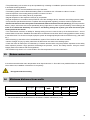
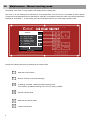
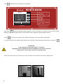
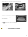
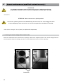
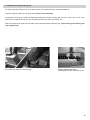
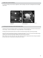
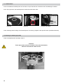
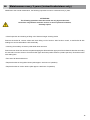
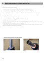
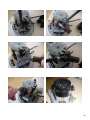
DIE ZUKUNFT DES HEIZENS
MAINTENANCE &
CLEANING
All types / Qualified personnel
T H E F U T U R E O F H E AT I N G
Only start-up the heating system after having read this assembly instruction manuals thoroughly!
Note
If you require customer service, please have the serial number as well as the exact system type ready. You can find this
information on the identifcation plate, which is located on the pellet daily tank.
System type
Serial number
This figure is a symbol image and does not necessarly correspond to the system type described in the present
instruction manual.
Content
01 General Information
4
02 Safety Notes
5
03 Return water riser
6
04 Minimum distance from walls
6
05 Maintenance – Manual working mode
7
06 Periodical maintenance for user
6.1 Emptying of the ash drawer / Cleaning of burner area
8
8
07 Annual maintenance (qualified technicians only)
7.1 Cleaning of induced draught fan and smoke tube
7.2 Verification of grate cleaning rod
7.3 Air flow sensors
7.4 Verify air mass sensors with an aggregate test
7.5 Boiler door (1) and ash draw (2)
7.6 Checking the functionality of the Heat Exchanger motor
7.7 Lambda Probe
7.8 Cleaning of exhaust gas probe
12
12
13
14
14
15
15
16
16
08 Maintenance every 3 years (trained technicians only)
17
09 Repair instructions for Leister Ignition Fan
18
10 Repair instructions for Amatek Turbine
20
11 Notes
22
01
General Information
• Our customer service or an authorized specialist contractor must carry out assembly, installation, and initial start-up
(setting) of our pellet heating system.
• Recommendation: For long burner running times, in order to reduce the start-stop emissions and to reduce maintenance
costs, the boiler should be fitted with a buffer storage tank, thermosiphon buffer storage tank or combination storage
tank. In practice, buffer capacities between 40 and 75 litres/kW have proven successful. Be sure to take into account the
country-specific requirements regarding buffer storage tanks. The operation of the system is only permissible if it can be
guaranteed that the boiler‘s nominal heat output can be reduced by 50% for a period of at least 2 hours.
• Use only those fuels recommended by us - wood pellets pursuant to EN 14961-2, Class A1+ A2 (Ø 6 mm). Only in this
way can low-emission, economic, and trouble-free operation of your pellet heating system be ensured. Non-compliance
will result in voiding of the guarantee.
• At regular intervals, perform the maintenance and cleaning procedures recommended by us in the manual for your pellet
heating system. When this is done you not only ensure the functional reliability of the system and its safety systems, but
also efficient, low-emission operation of the system. You achieve the best care of your pellet heating system by concluding
a maintenance contract. The indicated cleaning and maintenance intervals must be unconditionally respected. Please
note that, no warranty claim arises for damage that is the result of non-compliance with the maintenance instructions.
• Your heating boiler is adjustable within an output range of 30% to 100% of the rated output. The units should be
operated if at all possible in the middle and upper output range (adjusted to the respective heat requirement),
in order to avoid unnecessary emissions in low load operation. The ideal is the combination with a modulating room and
heating regulator in order to avoid unnecessary cycles and to enable the longest possible running times.
• If technical changes are undertaken independently, we assume no liability for damages that that may result thereof.
• Any procedure undertaken by persons other than those authorized by us, and non-compliance with these general
considerations and the safety notices described below, shall result in immediate voiding of any warranty claim as well
as the guarantee.
• Damaged parts and unit components must be replaced only with original replacement parts.
• It is urgently recommended that this manual be kept within reach in the heating room.
• The pellet heating system described in this manual has been tested in accordance with EN303-5.
• The generally applicable rules of heating technology must be observed for protection against Legionella.
• NOTE: When using pellet heating systems with 2 suction turbines (e.g. 100kW boiler) the daily tank is unequally
emptied (complete emptying cannot be ensured). We have already recommended in the planning a division of the
storage area of between 60 and 40%.
The mandatory maintenance of the system must be done by authorized technicians at least one
a year but no later than when reaching 1500 hours of operation (with an output range of 80-100%).
If NO service is performed, the warranty claim or the warranty is void!
• In the course of maintenance work on the pellet heating system all wear parts are replaced and billed, if necessary.
For service work to be performed, the system must be „cold“. If the system is not shut down in sufficient time and is still
“warm” when the service technician arrives, the resulting idle and waiting time will also be billed.
• Foreign bodies in the fuel can result in damage to the system.
• The regulations pursuant to A-Norm M 7136 (Transport and Storage Logistics) and M 7137 (Pellet Storage Requirement)
must be observed.
• Please note that you must observe the prescribed servicing intervals during the warranty period!
• Properties that require a high degree of security for heat supply (the hotel business, process heating, etc.) are to be
equipped with dual boiler systems. If this requirement is not met, we will deny any claims for consequential damage
based on a faulty heating source. In a biomass heating system, it is essential to take appropriate care ( caretaker,
porter, etc.) so that the stipulated maintenance tasks are carried out regularly!
4
• Datasheet on Wood Pellets pursuant to EN 14961-2, Classes A1 + A2 (Ø 6 mm)
Parameters (Unit)
ENplus-A1
Length (mm)
up to 40
Fines (%, mass)
≤12
1
ENplus-A2
up to 40 1
≤12
Ash content (%, mass)
≤ 0,7
Ash melting temp. (°C)
≥ 1.200
3
≤ 1,0 3
≥ 1.100
1) Maximum 5% of the pellets may be longer than 40 mm, max. length 45 mm.
2) Particles < 3.15 mm, fines at the last loading site.
3) In a water-free state (wf)
YMM 3x2.5 mm cable 2; electrical connection: 230 V, 50 Hz; fusing 16 A, slow triggering.
Protection with protective multiple earthing with fault-current circuit breaker
(voltage limits pursuant to EN 50160) ATTENTION: ISO Norm 60364 must be observed!
Operational limits: Max. ambient temperature 0-45 °C; max humidity 0-95%
We assume warranty obligations in accordance with the provisions of our warrantee conditions
only when original Biotech replacement parts are used. Biotech grants repair service and
supply of replacement parts for at least 10 years from the date of purchase of the system!
02
Safety Notes
A heating emergency switch (all-phase multidirectional switch off) must be arranged upstream of the
combustion chamber! Switch it off before carrying out the maintenance and/or service work!
The safety notes must absolutely be read before operating the system! Non-compliance with the
safety notes can result in physical injury, life-threatening situations, or damage to the system!
• The pellet heating system may be operated only in technically perfect condition. Malfunctions and damage that
adversely affect or are capable of adversely affecting safety, must be resolved promptly by our technical personnel.
• Assembly must be done only by our customer service or by an authorized technical contractor . The system includes
rotating parts that are driven at relatively high torque (crushing hazard).
• Live voltage parts are located under the enclosure and in the junction boxes. Therefore never remove enclosure parts
or never open the junction boxes!
• During running operation never open the maintenance ports of the boiler; hot flue gas and dust can escape.
• The system must be switched off prior to carrying out any maintenance. Use the ON/OFF switch to switch off
the system. Wait until the system is cooled down (please refer to the boiler temperature on the display). Then switch the
system off using the Heating Emergency OFF Switch. Secure the switch against accidental switch-on of the system.
• Before sweeping the heating tube or the chimney by the chimney cleaner, switch off the system using the ON/
OFFswitch and wait for the burn-out process (about 20 minutes). Explosion hazard due to flue gas congestion.
• Never empty flammable liquid into the combustion chamber.
• Never perform repair work yourself on our systems but rely on our technical personnel. A warning sign „Smoking and
tampering with open flame and fire is prohibited“ must be posted (hazard when refilling the pellet hopper).
• A certified fire extinguisher must be provided in the heating room.
• Ensure an adequate supply of fresh air.
• Secure the heating room against unauthorized access, especially by children.
• The boiler doors and the water-side connections must be inspected once a month for tightness and damage.
• The safety temperature limiter (STL) must be inspected once a year (this should be done during maintenance or
service).
• Safety and monitoring devices must not be removed, bypassed or in any other way made inoperative.
• When cleaning and when removing ashes use a dust mask in order to prevent hazards to health and damages.
• When filling the fuel bunker using pump vehicles, the system must be switched off (waiting time: 20 minutes).
• When setting the non-potable water temperature above 60 ºC ensure an appropriate mixture of cold water (scalding
hazard).
5
• The pellet heating unit must be set up and operated only in heating or installation spaces that have been constructed
in accordance with regulations.
• A suitable vent valve must be installed on the top of the boiler.
• The heating system must be filled with heating water in accordance with VDI 2035 or A-Norm H 5195-1.
• Annual inspection of the heating water pursuant to A-Norm H 5195-1.
• Annual inspection of the safety valves by a specialist.
• Regular inspection of the expansion reservoir by a specialist.
• Regular inspection in accordance with prTRVB H 118 of the discharge device, automatic wood firing systems, loader.
• Fire prevention specifications that are compliant with the applicable regulatory provisions must be implemented!
• Please note that even when the system is switched off, different functions are still operating! (The frost protection
device, pumps, and mixers are moved periodically during night times in order to prevent sticking of the bearings). In
order to be certain that absolutely no current is still flowing through the system, you must disconnect your
heating unit from the mains!
• The manufacturer assumes no liability for damage arising from an incorrect hook-up of the flow and return – do not
confuse these connections. Establish removable and non-distorted connections. When routing pipelines ensure venting
of the boiler block. For the event of repair, equip the system at the appropriate point with shut-off devices (e.g. ball valve
etc.).
• Before hooking up the boiler to the heat distribution system: Flush the lines and remove residues.
• Caution: Danger of injury by safety valve blow-off! Direct blow-out water to the drainage point.
• Check the boiler for leaks prior to initial start-up. Pressure test the boiler using the pressure equivalent to the safety
valve response pressure. Large pressure will damage the pressure, control, and safety devices. Carryout closure
integrity tests in accordance with local regulations.
• Fill the boiler only when it is in a cold condition The flow temperature must not exceed 40°C
03
Return water riser
It must be ensured that the return temperature never drops below 55 °C. Since this is not possible without an automatic
return water riser, installation of the device is compulsory.
Disregard voids the warranty.
04
Minimum distance from walls
Model
To the back [mm]
Left side to wall [mm]
Right side to wall [mm]
Top Light Top Light M
0 - 100
0 - 100 *
400
0 - 100
0 - 100 *
400
Top Light M
PZ8RL
MBW
0 - 100
280
0 - 100 *
0 - 100 *
400
400
PZ25RL
280
0 - 100 *
400
PZ35RL
280
0 - 100 *
400
* … Recommendation from at least 250 mm, otherwise increased maintenance (costs)
6
05
Maintenance – Manual working mode
The display of this menu is only possible if the display shows „Heating OFF“.
This menu is for the cleaning and maintenance of the pellet boiler. From this menu it is possible to select specific
components of the pellet boiler and to operate them manually. It is possible to select this menu only with the pellet boiler
switched off. An asterisk “*” on the display (see induced draught) will warn you if the heating system is ON.
THE PELLET HEATING
SERVICE
F1
F2
F3
F4
* C
E
=
=
=
=
=
=
Exhaust measure
PELL-SUCTION
HEAT E.CLEAN
WORM SCREW
BURNER GRATE
INDUCED DRAF
CONFIRM
WE 24.05.06
07:22:26
HEATING OFF
ON/OFF
ON
OFF
MENU
PLEASE NOTE!
Do not operate the system before having read these instructions thoroughly!
Activate the following functions by pressing the successive keys:
... starts the suction turbine
... tarts the cleaning of the heat exchanger
... by keeping it pressed, it starts the pellet metering screw;
it is necessary to refill the metering screw if it runs empty of pellets
... opens the burner grate ... starts the flue gas exhauster
... confirm maintenance
7
MESSAGE
06
Periodical maintenance for user
In order to maintain the performance of your Biotech boiler system a periodic cleaning regime is necessary.
6.1 Emptying of the ash drawer / Cleaning of burner area
Depending on the pellet boiler model / working hours / pellet quality, the ash drawer needs to be emptied once every
6-18 weeks. The ash drawer is located on the bottom left of he boiler and is closed via the ash door (fastened by two
screwed rotating handles.).
• Procedure
ATTENTION: Never take out hot or glowing ashes !
Switch off the heating system by means of ON / OFF key.
ATTENTION: After switchingoff the system, please let it cool down for at least 2-3 hours before you can proceed with the
following maintenance operations:
ATTENTION:
After switching-off the system, please let it cool down for at least 2-3 hours
Damage caused by the non-compliance with maintenance instructions will not be
covered by warranty!
THE PELLET HEATING
M A I N M E N U
1
2
3
4
5
6
OPERATION MODE
P. BOILER SERVICE
D. HOT. W. TANK SETTING
PELLETS-FILL TIME LCD +
SERVICE MANUAL
LCD AGGREGATE TEST
WE 24.05.06
08:07:37
HEATING OFF
• Await the cooling of the heating system (see heating unit temperature
Exhaust measure
on the display)
• Call the Maintenance – annual working mode menu as follows:
• Press
until you are back in main menu
• By means of arrow keys
ON/OFF
move the white bar to the line
Maintenance - Manual
ON
OFF
MENU
MESSAGE
PLEASE NOTE!
Do not operate the system before having read these instructions thoroughly!
8
• Press
(maintenance menu appears on the display)
THE PELLET HEATING
SERVICE
F1
F2
F3
F4
C
E
=
=
=
=
=
=
Exhaust measure
PELL-SUCTION
HEAT E.CLEAN
WORM SCREW
BURNER GRATE
INDUCED DRAF
CONFIRM
WE 24.05.06
07:22:26
HEATING OFF
ON/OFF
ON
OFF
MENU
MESSAGE
PLEASE NOTE!
Do not operate the system before having read these instructions thoroughly!
• By pressing
the heat exchanger cleaning will start. Let it run for approx. 5 minutes in order to permit a deep
cleaning of the heat exchanger pipes. The procedure will be stopped by pressing again this key.
• Press
to open the burner grate; the ashes fall directly onto the ash drawer underneath.
• In order to prevent dust escaping while opening the boiler door, start the flue gas exhaustern by means of
ATTENTION:
If the display turns black (after approx. 10 minutes),
all aggregate units automatically switch off !ADVICE: If you wish to restart an
aggregate unit, start it again with the correspondent key!
• Open the covering door (or remove front cover) in order to have access to the burner cleaning door
9
• Open the lower cleaning door (fastened with star grips) / wing nuts) to get to the ash chamber..
• Take out the ash drawer from the lower cleaning opening (ash chamber) and empty it.
• Open the upper cleaning door (fastened with 2 star grips) and keep the emptied Ashtray under it.
Fig.: Cleaning door
• Remove flue ash which remains around the burner (ash scraper available at Biotech or at your local distributor). Also
clean the area around the pellet discharge slides (see pictures below).
10
• Remove the residual ashes with a vacuum cleaner until the burner area is completely clean
• By means of an vacuum cleaner, remove the residual ash on the
ash chamber
• Put back the ash drawer into its original position
• Close both cleaning doors
• Press
to confirm the cleaning operation (all aggregates switch off)
• The removed ashes may be used as fertiliser or disposed with biological waste
• Restart the heating system.
The cleaning procedures described above can be carried out in the
course of the annual service by trained personnel!
11
07
Annual maintenance (qualified technicians only)
ATTENTION:
The following operations must be carried out only by an authorised technician
or by Biotech customer service. Failure to comply will invalidate your warranty.
• Procedure
ATTENTION: Never remove hot or glowing ashes !
Turn off the system by means of the ON/OFF key and let it burn out. Then unplug the heater
via the emergency switch or the fuse, to secure the system from accidental re-starting.
• Wait for the cooling-off of the system (see pellet boiler temperature)
7.1 Cleaning of induced draught fan and smoke tube
Clean the smoke tube via the inbuilt service openings. Remove the inspection plate of the induced draught fan and
remove deposits. After this cleaning operation, close and fasten all revision and service openings.
SerieTop Light
Model PZ
Service lid
12
7.2 Verification of grate cleaning rod
To verify the grate cleaning rod, open both covers of the pellet tank with a head screwdriver.
Press the release switch of the grate rod and that it runs smoothly.
If the grate rod is locked, control the distance between the sensor and the gear rod: min. 2 mm, max. 4 mm. Only
within this interspace the sensor can recognise whether the grate is closed or not.
After verifying that the grate runs smoothly and controlling/setting ofsensor gap, lubricate the grate cleaning rod
with copper paste.
Fig.: grate rod, test it for smoth running
Distance between the sensor
and the gear rod: Min. 2mm, Max. 4 mm..
13
7.3 Air flow sensors
ATTENTION: Unplup the heating system!
With a torch you can control the sensors. If there isany deposit, clean them as follows:
When dismantling the secondary air fan, you canclean the sensor carefully with a long brush.
If you want to take out the sensor for cleaning, remove the plug and pull out the sensor with great caution.
Now you can clean the sensor with an appropraite brush. Build-in the sensor hermetically afterwards. Then, connect it
correctly and fasten it with a wire strap on the wind tube. After visual ispection and/or cleaning, control the air mass
sensors with an agregate test.
ATTENTION for Model PZ 35:
Don‘t confuse the sensors for primary and secondary air!
7.4 Verify air mass sensors with an aggregate test
At a tension of 15 Volts the primary fan should reach a value of approx. 160-200 (depends on type of system). Information
for Model PZ 35: the set value of the primary air mass sensor first rises to 200 and then changes to zero at full
performance.
With the button
you can now set back the tension to 0,00 V in order to repeat this procedure with the secondary fan.
Consider plug-in direction:
Sensors in the wind tube must face to the external side of the boiler!
When assembling the air mass sensor
and the wind tube, ensure 100 % leak tightness
14
7.5 Boiler door (1) and ash draw (2)
To control the sealings, remove the lid. If applicable, clean the sealings, check them for leak tightness and if damaged,
replace them.
➊
➋
1 Boiler door
2 Ash draw
Excentric plate (heat exchanger cleaning motor)
with steering arm
7.6 Checking the functionality of the Heat Exchanger motor
Let the motor of the heat exchanger cleaning run in the program of “Manual maintenance” and make sure that the lever
of the cleaning – above the excentric plate - is fully pressed down, to hoist the lifting-rods.
The lifting-rods are hoisted and then after one rotation of the heat exchanger cleaning motor they fall audibly.
If the lever of the heat exchanger cleaning is not fully pressed down, loosen the four screws of the heat exchanger
cleaning motor to decrease the interspace between the excentric plate and the lever
Hint: Lubricate the excentric plate with copper paste. Make sure that the copper paste remains during the operation
(excentric plate must run freely without touching the boiler isolation).
15
7.7 Lambda Probe
At the PZ models the lambda probe can be either on top at the boiler lid or behind at the induceddraught container.
At the Top Light series, the lambda probe is beside the smoke tube outlet.
Lambda probe
smoke tube
outlet
Model PZ
Model PZ
Top Light, Top Light M
Check fastening and air sealing of the lambda probe. If necessary, retighten it with special wrench (available at Biotech).
7.8 Cleaning of exhaust gas probe
Check for deposits and if necessary, clean it.
Attention:
There may be dust under the container of the worm mechanism.
Remove dust and seal it with silicone.
Flange bracket (container worm)
16
08
Maintenance every 3 years (trained technicians only)
Additional to the annual maintenance, the following inspections must be conducted every 3 years.
ATTENTION:
The following operations must be carried out only by an authorised
technician or by Biotech customer service. In case of personal initiatives,
warranty expires
• Visual inspection and cleaning of lifting rod of heat exchanger cleaning device
Remove the boiler lid, remove ashes and check lifting rod for function. After function control, re-seal boiler lid with
sealing lace and re-assemble the lid hermetically.
• Cleaning of secondary air area in pellet boiler lower structure
Remove burner inner door and remove pellet dropping bar. Dismantle the upper part of the boilerand clean the secondary
air area with a vacuum cleaner. Check the boiler upper and lower partfor abrasion (visual inspection). Re-seal the boiler
with sealing lace.
• Run test of all electrical devices
• Replace brushes of the ignition blower (after approx. 500 hours of operation)
• Replace brushes of suction turbine (after approx. 500 hours of operation)
17
ZU LEISTER
09 REPARATURANLEITUNG
Repair instructions for Leister
IgnitionZÜNDGEBLÄSE
Fan
Diese Anleitung ist dazu gedacht, unseren Vertriebspartnern und deren Kundendienstmonteuren die
Vorgehensweise
beim Austausch der Kohlebürsten, bzw. den Austausch der
1. Replacement
of the
ignition cartridge
Zündpatrone bildlich darzustellen, und mit wenigen Worten zu erklären.
• unscrew and remove 4 screws affixed on the face of the tubular cable protection (pic. 1)
1. Austausch
Zündpatrone:
• remove
the tubularder
cable
protection, the washer gasket as well as the insulation tube (pic. 2)
• separate the ignition cartridge from the plug contact by pulling it off (pic. 3)
• ignition
4 Stk. stirnseitig
amthe
Schutzrohr
sitzende
lösen the
undfan
abnehmen
(Bild 1)order
• push the new
cartridge into
plug contact
entirelySchrauben
and reassemble
again in reversed
• Schutzrohr, Dichtungsscheibe und das Isolierrohr abnehmen
(Bild2)
• Die Zündpatrone durch ziehen vom Steckkontakt am Gehäuse trennen (Bild 3)
• Die
Neue
Zündpatrone
2. Replacement
of the
carbon
brushes vollständig in den Steckkontakt schieben, und dann das
Gebläse in umgekehrter Reihenfolge wieder zusammenbauen.
• remove the rubber grommet by simply stripping it off forward (pic. 4)
• unscrew and remove the 3 screws (pic. 5)
2. ofKohlebürsten
• pull
the engine casetauschen
backwards
• open the brazen lug of the brush holder. Make sure that the spring which presses the carbon brush onto the collector
• outEntfernen
(Bild 4)
doesn’t jump
(pic. 6) der Gummitülle durch einfaches abziehen nach vorne
• Lösen
entfernen
derof3 the
Schrauben
(Bild 5)
• pull the spring
with theund
carbon
brush out
brush holder (pic. 7)
• insert the •newAbziehen
carbon brush
with spring; pushnach
the spring
des Motorgehäuses
hintenback into the brush holder entirely, and after this cap the
opening via•the Öffnen
brazen lug
reassemble
in
reversed
order
der Messinglasche des Bürstenhalters. Aufpassen, dass dabei die Feder,
•
•
•
welche die Kohlebürste an den Kollektor drückt, nicht herausspringt
(Bild 6)
Feder mit Kohlebürste aus dem Bürstenhalter ziehen.
(Bild7)
Neue Kohlebürste mit Feder einschieben; die Feder wieder vollständig in den
Bürstenhalter schieben, und danach die Öffnung mit der Messinglasche
verschließen
Der Zusammenbau erfolgt danach wiederum in umgekehrter Reihenfolge.
Bilder zum Austausch der Zündpatrone
Illustrations to the replacement of the ignition cartridge
pic. 1
Bild 1
18
pic. 2
Bild 2
pic. 3
Bild 3
Illustrations to the replacement of the carbon brushes
Bilder zum Austausch der Kohlebürsten
pic.
Bild4 4
pic.
Bild5
5
pic.
Bild6 6
pic.
Bild7
7
19
10
Repair instructions for Amatek Turbine
REPARATURANLEITUNG ZU AMETEK TURBINE
Replacement
of the carbon
Diese Anleitung
ist brushes
dazu gedacht,
unseren Vertriebspartnern und deren Kundendienstmonteuren die Vorgehensweise beim Austausch der Kohlebürsten, bildlich darzustellen, und
• before
to the
carbonzu
brush
holder, you need to remove the black PVC casing. To do so, please bend the spring
mitgetting
wenigen
Worten
erklären.
clips, which fix the brush holder, slightly outwards.
• afterKohlebürsten
bending these lugs
so far outwards that they don’t put up any further resistance, you can take off the PVC casing
tauschen
by removing the screws of the spring clips using a cross slot screwdriver
•
Bevor man an den Kohlebürstenhalter herankommt, muss das schwarze PVC Ge-
•
Nachdem beide Laschen soweit nach außen gebogen sind, dass sie das abheben
• then pull away the
brush
holder a bit backwards
and slightly
twist
it, so that you can
shift the
lug out of the
häuse
abgenommen
werden. Dazu
sind die
Federklemmen,
welche
dencontact
Bürstenbrush holder with halter
the screwdriver
fixieren, leicht nach außen hin zu verbiegen.
• after pulling the des
contact
lugGehäuse
out of thenicht
retaining
bracket
entirely,kann
the brush
be removed together
PVC
mehr
behindern,
diesesholder
untercan
Zuhilfenahme
eines with the
carbon brush andSchraubenziehers
get replaced by an abgehoben
original spare
part. While assembling the new brush holder, please take care that
werden.
the contact lug
is
being
pushed
against.
• Jetzt sind mit einem Kreuzschlitz Schraubenzieher die Schrauben der
Federklemmen zu entfernen, und abzunehmen.
• pull tight the•spring
clips and put den
the PVC
casing back again
Therefore,
back-bend
spring clips to
Anschließend
Bürstenhalter
etwasin target
nach state.
hinten
wegziehen
und the
leicht
their original position.
verdrehen, damit man mit einem Schraubenzieher die Kontaktlasche aus dem
•
•
Bürstenhalter herausschieben kann.
Nachdem die Kontaktlasche vollständig aus der Halterung gezogen wurde, kann
der Bürstenhalter inklusive der Kohlebürste entfernt werden, und gegen ein
Original Ersatzteil getauscht werden. Beim Einbau des Neuen Bürstenhalters ist
darauf zu achten, dass die Kontaktlasche auch wieder bis zum Anschlag
eingeschoben wird.
Nach dem festziehen der Federklemmen kann das PVC Gehäuse wieder
aufgeschoben werden. Damit dieses wieder fest sitzt sind die Federklemmen
wieder in die ursprüngliche Form zurückzubiegen.
Illustrations
chronological
arranged Reihenfolge
Bilderserie
in chronologischer
20
21
11
22
Notes
11
Notes
23
11
24
Notes
11
Notes
All technical changes and printing errors reserved.
25
26
012011
T H E F U T U R E O F H E AT I N G
Biotech Energietechnik GmbH
Furtmühlstraße 32
A-5101 Bergheim bei Salzburg
Tel.: +43 662 454072 0
Fax: +43 662 454072 50
[email protected]
www.pelletsworld.com