1
Manual No. '11 • SAF-T-161
updated March 31, 2011
TECHNICAL MANUAL
VRF INVERTER MULTI-SYSTEM AIR CONDITIONERS
Alternative refrigerant R410A use models
Fresh Air DX Assembly
(SAF-DX)
Models
SAF-DX250E6 SAF-DX350E6 SAF-DX500E6
SAF-DX800E6 SAF-DX1000E6
•
Note:
(1) Regarding the Outdoor unit series, refer to the following table.
Technical manual
Reference manuals No.
Data book
Service manual
4㨪6HP
'08 • KX-T-117
̆
̆
8㨪12HP
̆
'09 • KX-DB-124
'09 • KX-SM-125
14㨪48HP
̆
'09 • KX-DB-127
'09 • KX-SM-128
Heat recovery
3-pipe ststems
̆
'09 • KXR-DB-129
'09 • KXR-SM-130
Models
'11•SAF-T-161
CONTENTS
1. What is SAF-DX.............................................................................................. 1
2. Specifications................................................................................................. 3
3. Exterior dimensions....................................................................................... 4
4. Electrical wiring.............................................................................................. 13
5. Internal resistance characteristics............................................................... 14
6. Range of usage & limitations........................................................................ 15
7. Operation control function by the indoor controller................................... 16
8. User's manual................................................................................................. 22
9. Installation manual......................................................................................... 23
10. Application example....................................................................................... 32
'11•SAF-T-161
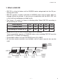
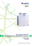
1. What is SAF-DX
•SAF-DX is a kind of indoor unit for KX(R)E6 series categorized into the OA processing unit series.
• SAF-DX consists of indoor controller of KX(R)E6 series and an indoor heat exchanger without any blower. It can be use in combination with the MHI’s SAF unit
or the total heat exchanger provided locally.
• The lineup is 5 models as shown in following table. Select SAF-DX according to
the processing air volume.
Model capacity
250
350
500
800
1000
Capacity code
22
28
36
56
71
Processing air volume (m3/h)
250
350
500
800
1000
• Mixed use of SAF-DX with KX(R)E6 indoor unit is available.
(Total connectable capacity of KX(R)E6 indoor units including SAF-DX must be
within 100% of outdoor unit capacity)
• Connectable outdoor unit are all KX(R)E6 series (5 to 48HP)
• All two-wire remote controller are available, and all center console also can be
used.
KXE6
KXRE6
FDT
SAF-DX
RC-E4
RC-E4
RC-E4
RC-E4
-
-
SL3N
#
'11•SAF-T-161
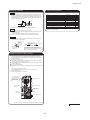
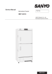
• SAF-DX is a kind of indoor unit for KX(R)E6 series without any blower and fan.
• The intake OA can be conditioned in cooling or heating at the heat exchanger section of SAF-DX by utilizing the blower function of MHI’s SAF unit or the total heat
exchanger provided locally.
FAN
OA
RA
SAF-DX
Total heat
exchanger
EA
SA
• The control of total heat exchanger must be interlocked with SAF-DX.
• Both return air temp. control and supply air temp. control are applicable. (Switching
the control method can be done with the Dip-SW on the control PCB.)
RA
OA
Total heat
exchanger
Return/fresh air
temp. sensor
SAF-DX
supply/fresh air
temp. sensor
SA
EA
SW7-3
interlock
ON
Control of total heat exchanger
OFF
must be interlock with SAF-DX
Switching between return/supply air temp. control
-
-
N:
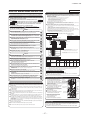
1RPLQDOKHDWLQJFDSDFLW\
3RZHUVRXUFH
&RRO
3RZHUFRQVXPSWLRQ
+HDW
&RRO
5XQQLQJFXUUHQW
+HDW
6RXQG3UHVVXUH/HYHO
([WHULRUGLPHQVLRQV
+HLJKW[:LGWK['HSWK
1HWZHLJKW
:
SAF-DX350E6
SAF-DX500E6
SAF-DX800E6
9ᨺ+]
9ᨺ+]
9ᨺ+]
9ᨺ+]
9ᨺ+]
SAF-DX1000E6
G%$
PP
NJ
/RXYHUILQLQQHUJURRYHGWXELQJ
/RXYHUILQLQQHUJURRYHGWXELQJ
/RXYHUILQLQQHUJURRYHGWXELQJ
/RXYHUILQLQQHUJURRYHGWXELQJ
/RXYHUILQLQQHUJURRYHGWXELQJ
(OHFWURQLF([SDQVLRQ9DOYH
(OHFWURQLF([SDQVLRQ9DOYH
(OHFWURQLF([SDQVLRQ9DOYH
(OHFWURQLF([SDQVLRQ9DOYH
(OHFWURQLF([SDQVLRQ9DOYH
$
5HIULJHUDQWHTXLSPHQW
+HDWH[FKDQJHU
5HIULJHUDQWFRQWURO
$LUKDQGOLQJHTXLSPHQW
)DQW\SH4
W\
0RWRU
SAF-DX250E6
:
6WDUWLQJPHWKRG
$LUIORZ6WDQGDUG
&0+
,QWHUQDO5HVLVWDQFH
3D
-
-
2XWVLGHDLULQWDNH
$LUILOWHU4
W\
6KRFNYLEUDWLRQDEVRUEHU
3RO\XUHWKDQHIRUP
3RO\XUHWKDQHIRUP
3RO\XUHWKDQHIRUP
3RO\XUHWKDQHIRUP
3RO\XUHWKDQHIRUP
2SHUDWLRQFRQWURO
5HPRWHFRQWUROVZLWFK
5HPRWHFRQWUROVZLWFK
5HPRWHFRQWUROVZLWFK
5HPRWHFRQWUROVZLWFK
5HPRWHFRQWUROVZLWFK
2SHUDWLRQVZLWFK
2SWLRQ5&(
2SWLRQ5&(
2SWLRQ5&(
2SWLRQ5&(
2SWLRQ5&(
5RRPWHPSHUDWXUHFRQWURO
7KHUPRVWDWE\HOHFWURQLFV
7KHUPRVWDWE\HOHFWURQLFV
7KHUPRVWDWE\HOHFWURQLFV
7KHUPRVWDWE\HOHFWURQLFV
7KHUPRVWDWE\HOHFWURQLFV
6DIHW\HTXLSPHQW
)URVWSURWHFWLRQWKHUPRVWDW
)URVWSURWHFWLRQWKHUPRVWDW
)URVWSURWHFWLRQWKHUPRVWDW
)URVWSURWHFWLRQWKHUPRVWDW
)URVWSURWHFWLRQWKHUPRVWDW
㪣㫀㫈㫌㫀㪻㩷㫃㫀㫅㪼㪑㩷㱢㪍㪅㪊㪌㩷㩿㪈㪆㪋㩹㪀
㪣㫀㫈㫌㫀㪻㩷㫃㫀㫅㪼㪑㩷㱢㪍㪅㪊㪌㩷㩿㪈㪆㪋㩹㪀
㪣㫀㫈㫌㫀㪻㩷㫃㫀㫅㪼㪑㩷㱢㪍㪅㪊㪌㩷㩿㪈㪆㪋㩹㪀
㪣㫀㫈㫌㫀㪻㩷㫃㫀㫅㪼㪑㩷㱢㪍㪅㪊㪌㩷㩿㪈㪆㪋㩹㪀
㪣㫀㫈㫌㫀㪻㩷㫃㫀㫅㪼㪑㩷㱢㪐㪅㪌㪉㩷㩿㪊㪆㪏㩹㪀
㪞㪸㫊㩷㫃㫀㫅㪼㪑㩷㱢㪐㪅㪌㪉㩷㩿㪊㪆㪏㩹㪀
㪞㪸㫊㩷㫃㫀㫅㪼㪑㩷㱢㪐㪅㪌㪉㩷㩿㪊㪆㪏㩹㪀
㪞㪸㫊㩷㫃㫀㫅㪼㪑㩷㱢㪈㪉㪅㪎㩷㩿㪈㪆㪉㩹㪀
㪞㪸㫊㩷㫃㫀㫅㪼㪑㩷㱢㪈㪉㪅㪎㩷㩿㪈㪆㪉㩹㪀
㪞㪸㫊㩷㫃㫀㫅㪼㪑㩷㱢㪈㪌㪅㪏㪏㩿㪌㪆㪏㩹㪀
)ODUHSLSLQJ
)ODUHSLSLQJ
)ODUHSLSLQJ
)ODUHSLSLQJ
)ODUHSLSLQJ
5HIULJHUDQW
5$
5$
5$
5$
5$
'UDLQXSNLW
2SWLRQ';$'8(
2SWLRQ';$'8(
2SWLRQ';$'8(
2SWLRQ';$'8(
2SWLRQ';$'8(
,QVXODWLRQQRLVHKHDW
,QVWDOODWLRQGDWD
5HIULJHUDQWSLSLQJVL]H
&RQQHFWLQJPHWKRG
'UDLQKRVH
,QVXODWLRQIRUSLSLQJ
$FFHVVRULHV
&RQQHFWDEOHZLWKᨒᨌ᧮᧬
&RQQHFWDEOHZLWKᨒᨌ᧮᧬
&RQQHFWDEOHZLWKᨒᨌ᧮᧬
&RQQHFWDEOHZLWKᨒᨌ᧮᧬
1HFHVVDU\ERWK/LTXLG*DVOLQH
1HFHVVDU\ERWK/LTXLG*DVOLQH
1HFHVVDU\ERWK/LTXLG*DVOLQH
1HFHVVDU\ERWK/LTXLG*DVOLQH
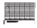
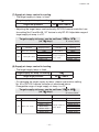
7KHGDWDDUHPHDVXUHGDWWKHIROORZLQJFRQGLWLRQV
$GDSWHGWRRoHS GLUHFWLYH
,QGRRUDLUWHPSHUDWXUH
2XWGRRUDLUWHPSHUDWXUH
6WDQGDUGV
,WHP
2SHUDWLRQ
'%
:%
:%
'%
ഒ
ഒ
ഒ
ഒ
&RROLQJ
,627
+HDWLQJ
ഒ
ഒ
ഒ
7KLVSDFNDJHGDLUFRQGLWLRQHULVPDQXIDFWXUHGDQGWHVWHGLQFRQIRUPLW\ZLWKWKHIROORZLQJVWDQGDUG
ᇫᇫ,62781,7$5<$,5&21',7,21(56
3RZHUFRQVXPSWLRQLQGLFDWHVWKDWRIFRQWUROFLUFXLWRQO\
ᨑVDJHOLPLWDWLRQRI6$)';FRQQHFWLRQZLWKWKH.;5(LQGRRUXQLW5HIHUWRSDJH
'11•SAF-T-161
PCH000Z360
1RWHV
&RQQHFWDEOHZLWKᨒᨌ᧮᧬
1HFHVVDU\ERWK/LTXLG*DVOLQH
2. Specifications
0RGHOV
1RPLQDOFRROLQJFDSDFLW\
0
φ1
5
160
340
170
Control box
19
362
□120
70
450
-
337
373
-
B
A
Remote controller
(Option)
(Suspension bolts pitch)
70
18
40
260
40
71 (Suspension bolts pitch)
Air supply duct
67
M10
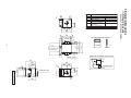
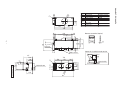
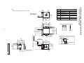
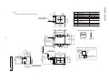
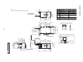
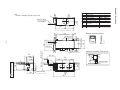
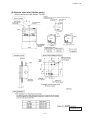
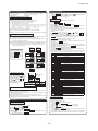
3. Exterior dimensions
170
Wiring hole for total enthalpy
heat exchanger
Hole for communication line
Suspension bolts
Models SAF-DX250E6, DX350E6
E
F
G
(1) Without Drain pump
C
Symbol
Contents
A Gas piping
φ9.52(3/8")
(Flare)
B Liquid piping
φ6.35(1/4")
(Flare)
C Drain piping
VP20
D Hole for power source line
64
200
170
□450
340
Inspection hole
'11•SAF-T-161
D
E
F
170
50
φ1
PCH000Z367
315
285
Space for installatin and service
160
264
67
27
G
Label,model name
220
Outdoor air duct
100
337
220
180
18
90
φ2
0
0
Symbol
Contents
A Gas piping
φ12.7(1/2")
(Flare)
B Liquid piping
φ6.35(1/4")
(Flare)
C Drain piping
VP20
D Hole for power source line
160
E
F
G
212.5
425
212.5
40
345
40
71 (Suspension bolts pitch)
67 Air supply duct
(Suspension bolts pitch)
19
18
70
Control box
□120
362
70
337
373
450
M10
Remote controller
(Option)
18
-
B
A
Wiring hole for total enthalpy
heat exchanger
Hole for communication line
Suspension bolts
Model SAF-DX500E6
C
64
90
100
212.5
160
264
315
285
Inspection hole
'11•SAF-T-161
220
D
E
F
00
φ2
PCH000Z366
Label,model name
200
425
67
27
G
212.5
Space for installatin and service
□450
337
220
180
Outdoor air duct
0
φ2
5
160
E
F
G
40
Control box
□120
19
18
70
450
-
337
373
-
B
A
M10
Remote controller
(Option)
362
Air supply duct
70
71
67
490
(Suspension bolts pitch)
18
40
570
250
(Suspension bolts pitch)
320
Wiring hole for total enthalpy
heat exchanger
Hole for communication line
Suspension bolts
Model SAF-DX800E6
C
Symbol
Contents
A Gas piping
φ12.7(1/2")
(Flare)
B Liquid piping
φ6.35(1/4")
(Flare)
C Drain piping
VP20
D Hole for power source line
64
90
200
570
250
0
682
'11•SAF-T-161
315
285
D
E
F
5
φ2
PCH000Z365
Label,model name
Inspection hole
160
264
67
27
G
320
□450
337
220
180
220
Space for installatin and service
100
Outdoor air duct
φ2
50
Symbol
Contents
A Gas piping
φ15.88(5/8")
(Flare)
B Liquid piping
φ9.52(3/8")
(Flare)
C Drain piping
VP20
D Hole for power source line
160
E
F
G
-
B
A
19
70
Control box
□120
362
Air supply duct
M10
Remote controller
(Option)
337
373
-
450
40
(Suspension bolts pitch)
71
67
630
(Suspension bolts pitch)
70
40
710
325
18
385
Wiring hole for total enthalpy
heat exchanger
Hole for communication line
Suspension bolts
Model SAF-DX1000E6
C
64
Outdoor air duct
190
160
264
Inspection hole
2-φ
200
D
E
F
822
'11•SAF-T-161
PCH000Z364
315
285
200
710
270
□450
250
67
27
G
Label,model name
220
Space for installatin and service
100
337
220
180
18
90
φ1
5
0
C2
160
Drain hose(Option)
Local installation
170
340
E
F
G
170
φ9.52(3/8")
(Flare)
φ6.35(1/4")
(Flare)
VP25 Notes(1)
VP20
M10
19
362
□120
18
(Max.Drain Lift)
57
D
E
F
100
200
340
170
□450
170
Inspection hole
160
264
315
285
295∼325
Space for installatin and service
'11•SAF-T-161
Label,model name
Outdoor air duct
50
φ1
PCH000Z372 A
220
90
G
600 or less
337
274
220
180
67
62
27
70
Control box
Hole for power source line
Wiring hole for total enthalpy
heat exchanger
Hole for communication line
Suspension bolts
(Suspension bolts pitch)
-
C1
B
A
Contents
Remote controller
(Option)
337
373
-
450
70
18
40
260
40
71 (Suspension bolts pitch)
Air supply duct
67
Gas piping
Liquid piping
Drain piping
Drain piping
Models SAF-DX250E6, DE350E6
Symbol
A
B
C1
C2
D
64
(2) With Drain pump (Option parts:DXA-DU-E)
Notes
(1)Please local arrange connected socket for VP25.
φ2
0
C2
Symbol
A
B
C1
C2
D
0
64
160
Drain hose(Option)
Local installation
212.5
425
E
F
G
212.5
40
345
40
71 (Suspension bolts pitch)
67 Air supply duct
Hole for power source line
Wiring hole for total enthalpy
heat exchanger
Hole for communication line
Suspension bolts
(Suspension bolts pitch)
φ12.7(1/2")
(Flare)
φ6.35(1/4")
(Flare)
VP25 Notes(1)
VP20
M10
19
18
100
200
212.5
□450
425
Inspection hole
160
264
315
285
212.5
57
600 or less
G
D
E
F
'11•SAF-T-161
Label,model name
Space for installatin and service
295∼325
00
φ2
PCH000Z371 A
220
Outdoor air duct
90
(Max.Drain Lift)
337
274
220
180
67
62
27
70
Control box
□120
362
70
18
-
450
Contents
Remote controller
(Option)
337
373
-
C1
B
A
Gas piping
Liquid piping
Drain piping
Drain piping
Model SAF-DX500E6
Notes
(1)Please local arrange connected socket for VP25.
Symbol
A
B
C1
C2
D
64
φ2
5
0
C2
160
Drain hose(Option)
Local installation
40
10 -
C1
B
A
φ12.7(1/2")
(Flare)
φ6.35(1/4")
(Flare)
VP25 Notes(1)
VP20
M10
Remote controller
(Option)
19
18
(Max.Drain Lift)
250
□450
570
57
320
200
100
295∼325
Inspection hole
682
'11•SAF-T-161
D
E
F
0
Label,model name
Space for installatin and service
160
264
315
285
Outdoor air duct
5
φ2
PCH000Z370 A
220
90
G
600 or less
337
274
220
180
67
62
27
70
Control box
□120
362
Air supply duct
337
373
-
450
490
(Suspension bolts pitch)
70
71
67
250
18
40
570
Contents
Hole for power source line
Wiring hole for total enthalpy
heat exchanger
Hole for communication line
Suspension bolts
(Suspension bolts pitch)
320
E
F
G
Gas piping
Liquid piping
Drain piping
Drain piping
Model SAF-DX800E6
Notes
(1)Please local arrange connected socket for VP25.
C2
Symbol
A
B
C1
C2
D
φ2
50
64
Drain hose(Option)
Local installation
160
E
F
G
11 -
C1
B
A
VP25 Notes(1)
VP20
M10
19
70
Control box
□120
362
Air supply duct
φ15.88(5/8")
(Flare)
φ9.52(3/8")
(Flare)
Remote controller
(Option)
337
373
-
450
40
Contents
Hole for power source line
Wiring hole for total enthalpy
heat exchanger
Hole for communication line
Suspension bolts
(Suspension bolts pitch)
71
67
630
(Suspension bolts pitch)
70
40
710
325
18
385
Gas piping
Liquid piping
Drain piping
Drain piping
Model SAF-DX1000E6
Notes
(1)Please local arrange connected socket for VP25.
100
190
Inspection hole
160
264
D
E
F
2-φ
200
Label,model name
200
710
270
□450
250
57
600 or less
67
62
315
285
18
(Max.Drain Lift)
G
Space for installatin and service
822
'11•SAF-T-161
PCH000Z369 A
220
Outdoor air duct
295∼325
27
337
274
220
180
90
'11•SAF-T-161
(3) Remote controller (Option parts)
• Wired remote controller (Model : RC-E4)
PJZ000Z274
-
12 -
Tr
CNN
F(3.15A)
WH
WH 1
CNW0
X6
RD
WH
RD
F(3.15A)
1
Y
RD 3
RD
Free cooling
I
1
CNH
BK
2
CNF
SW6
X3
24V
1
CNW2
WH
Y
X4
19V
CNW1
SW5
X2
X1
2
RD
RD
BR
BR
6
BK
BK
5
BK
4
BK
GR
3
BK
GR
2
BK
BK
1
BK
Control PCB
BK
BK
CNU
BL
Y/GN
Earth
Th I -AF
t°
220V-240V
RD
WH
N
Th I -A
t°
Connector for branching
controller of heat recovery
3-pipe systems
TB1
L
Th I -R3
t°
BK
2
RD
+12 1
CND
BL
2
Y
CNT3
SW1 SW2 LED・2
JSL1
5
Superlink(spare)
SW3 SW4 LED・3
CNK2
BK
SW7
6
※1
5 6
7
52X1
8
Heat exch(air)
operation
Humidifier
operation
Heat exch(air)
abnormal
F(0.16A)
CNR2
BL
TB3
1
Y
Y
M
1∼
DM
CNI2
WH
FS
51X1
5
1
3
1
BL
RD
WH
2
(Operation)
XR2 8 (Heating)
XR4
Thc
(Thermo ON)
(Inspection)
XR5(Remote operation input
:volt-free contact)
For heat recovery 3-pipe systems
XB1
XB3
XB2
XB4
X Y A B
Remote
controller
t°
4
5
7
RD
WH
CNT2 3
X Y
M
SM
CNK1
BK
CNA RD
1 2 3 4 5 6
CNB
WH
BL
RD
CNI
3
WH
Y
OR
BL
WH
RD
RD
TB2
CNR 1
RD
L
BR
9
M
WH
7
BK
<6>
5
UH H
WH
3 4
<5>
C
BR
XR2
3
WH
WH
5
<4>
CNM3 1
BR
13 -
1 2
<3>
8
WH
52X1
51X1
Y
5
<2>
Y
Y
-
<1>
3
Y
3
BL
+12 1
2
7
XR1
XR3
BL 4
Signal line
(Shielded cord)
Signal line
between indoor units
(20S)
(SVH)
(SVG)
(SVE)
SW5-2
SW6
SW7-1
SW7-2
SW7-3
SW7-4
TB1
TB2
TB3
Thc
Th I -A
Th I -AF
Th I -R1,2,3
Tr I
X1∼3,6
X4
XR2
52X1,51X1
■mark
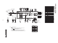
4. Electrical wiring
Power source line
between indoor units
220-240V∼ 50Hz
220V∼ 60Hz
Power source
Single-phase
Power
source
line
Th I -R2
t°
Connector
Drain motor
Fuse
Float switch
Live superlink terminal setting(for spare)
Indication lamp(Green-Normal operation)
Indication lamp(Red-Inspection)
Stepping motor(for electronic expansion valve)
Indoor unit address:tens place
Indoor unit address:ones place
Outdoor unit address:tens place
Outdoor unit address:ones place
Automatic adjustment/Fixed previous
version of Superlink protocol
Indoor unit address:hundreds place
Model capacity setting
Operation check,Drain motor test run
Reserved
Return/Supply air temp. control setting
Pressure setting
Terminal block(Power source)
(□mark)
Terminal block(□mark)
Terminal block(Signal line)
(□mark)
Thermistor(Remote controller)
Thermistor(Return air)
Thermistor(Service air)
Thermistor(Heat exchanger)
Transformer
Relay for FM
Relay for DM
Relay(DC12V)
Relay(AC200V)
Closed-end connector
Models All model
Th I -R1
t°
CNA∼Z
DM
F
FS
JSL1
LED・2
LED・3
SM
SW1
SW2
SW3
SW4
SW5-1
Option
'11•SAF-T-161
PCH000Z368 A
Notes 1. indicates wiring on site.
2. Use twin core cable(0.75∼1.25mm2)at signal line between indoor unit
and outdoor unit, and signal line between indoor units. 3. Terminal A B is signal terminal.(5volt)
4. Use twin core cable(0.3mm2)at remote controller line. (Refer to page 12)
of remote controller in case that the total length is more than 100m.
5. Do not put signal line and remote controller line alongside power source line.
Color Marks
Mark
Color
BK
Black
BL
Blue
BR
Brown
Gray
GR
Orange
OR
RD
Red
WH
White
Y
Yellow
Y/GN Yellow/Green
'11•SAF-T-161
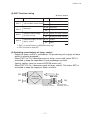
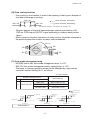
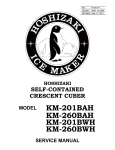
5. Internal resistance characteristics
100
90
80
70
Internal resistance [Pa]
60
50
40
SAF-DX1000E6
SAF-DX800E6
30
SAF-DX500E6
SAF-DX250E6,350E6
20
10
200
250 300 350 400
500
600
Air flow [m3/h]
-
14 -
800
1000 1200
(Refer to the front cover)
DX is
SAF-DX)
SAF-DX
DX is
-
15 3
3
'11•SAF-T-161
PCH000Z374
of the front cover)
of the front cover.)
3
6. Range of usage and limitations
(Refer to the front cover)
'11•SAF-T-161
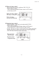
7. Operation control function by the indoor controller
(1) SAF-DX Control Section
Control box
Terminal block
for power cable *1)
*1)
The capacity of indoor
fan motor input is not
included.
SAF-DX
control PCB
Power line
Single phase
220-240V (50Hz)
Total heat exchanger
operation command
Return air temp. sensor
Supply air temp. sensor
Heat exchanger temp.
EEV coil.
sensor, RRT
Float switch.
Signal line
Remote controller line
(2) SAF-DX Control PCB
SW1-SW4: Address settings
CND
SW6: Capacity selection
SW7: Function setting
SW1-4 : Superlink address settings (indoor unit/outdoor unit).
SW6 : Capacity selection (no need to change).
SW7 : Function setting of SAF-DX. (See next page for details).
-
16 -
'11•SAF-T-161
(3) SW7 Function setting
䃨 factory default
SW
Function
SW7-1
Test run/drain motor check
SW7-2
Reserved
SW7-3
Switching return/supply
air temp. control
SW7-4
Automatic supply air temp. 䃨 Off Invalid
adjust. control
On
Valid
Setting
On/Off
䃨 Off Normal
On
Test run
䃨 Off Keep OFF
On
䃨 Off Ruturn air temp. control
On
Supply air temp. control
1. SW7-1 is same function for KX(R)E6 indoor unit
䋲. SW7-2 should be kept OFF.
(4) Switching return/supply air temp. control
・Supply air temp. control is available as OA processing unit (supply air temp.
sensor is already equipped.)
・When SW7-3 is Off, it become return air temp. control and indoor EEV is
controlled to keep the superheat of heat exchanger constant.
(factory setting, same as normal KX(R)E6 indoor unit)
・When SW7-3 is On, it become supply air temp. control. The indoor EEV is
controlled to keep the supply air temp. constant.
RA
SAF-DX
OA
Total heat
exchanger
SA
EA
return/fresh
air temp. sensor
-
17 -
supply/fresh
air temp. sensor
'11•SAF-T-161
(5) Return air temp. control
・Same control as normal air conditioner, RAC, PAC, KX...
・Thermo ON/OFF control :
Temp. difference between R/A temp. sensor (or R/C sensor)
and set temp. by R/C.
Return air temp. control
R/A temp. is set by R/C
Return air temp.
becomes Set R/A temp.
(6) Supply air temp. control
・Target S/A temp. is fixed and can be adjusted by RC-E3/4.
・Thermo ON/OFF control :
Temp. difference between R/A temp. sensor (or R/C sensor)
and set temp by R/C (same as return air temp. control)
・Cooling : Set return air temp. must be greater than Target supply temp.
Heating : Set return air temp. must be less than Target supply temp.
(If not, Set temp. becomes Target supply temp.)
Return air temp.
≒Set R/A temp.
Supply air temp.
≒Target S/A temp.
-
18 -
'11•SAF-T-161
(7) Supply air temp. control in cooling
・The target supply air temp. is fixed.
Target supply air temp. in cooling
Target supply air temp. in cooling
Target low pressure
Target low pressure
15㷄
15㷄
LP㻍0.65-0.76MPa
LP㻍0.65-0.76MPa
・Adjusting the target temp. can be done by RC-E3/4 remote controller function setting No.01 and No.08. “01” feature is only RC-E3. Adjustable range of
target supply air temp. is ±3℃.
Target supply air temp. can be set from 12㷄 to 18㷄.
to 18㷄.
Target supply air temp.
be set from 12㷄
(at 1㷄can
step)
䃨 Factory default
(at 1㷄 step)
䃨 Factory default
Indoor unit function
Indoor unit function
Function
Display on R/C
No.
No.
Function
01
㪘㫌㫋㫆㩷㪽㫀㫃㫋㪼㫉㩷㪺㫃㪼㪸㫅㫀㫅㪾
01
㪘㫌㫋㫆㩷㪽㫀㫃㫋㪼㫉㩷㪺㫃㪼㪸㫅㫀㫅㪾
08
08
㪟㪼㪸㫋㫀㫅㪾㩷㪪㪧㩷㫆㪽㪽㫊㪼㫋
㪟㪼㪸㫋㫀㫅㪾㩷㪪㪧㩷㫆㪽㪽㫊㪼㫋
Display
on R/C
䃨Invalid
Valid
Invalid
䃨
offset
䃨NOValid
Offset
+1.0
㷄
䃨NO offset
Offset
+2.0
Offset +1.0㷄㷄
Offset
Offset+3.0
+2.0㷄㷄
Offset +3.0 㷄
Actual meaning
FunctionActual meaning
Meaning
Function
㪪㫎㫀㫋㪺㪿㫀㫅㪾
㪧㫃㫌㫊㪆㪤㫀㫅㫌㫊
㪪㫎㫀㫋㪺㪿㫀㫅㪾
㪧㫃㫌㫊㪆㪤㫀㫅㫌㫊
㪫㪸㫉㪾㪼㫋㩷㫊㫌㫇㫇㫃㫐㩷㪸㫀㫉
㫋㪼㫄㫇㪅㩷㫆㪽㪽㫊㪼㫋㩷
㪫㪸㫉㪾㪼㫋㩷㫊㫌㫇㫇㫃㫐㩷㪸㫀㫉
㫋㪼㫄㫇㪅㩷㫆㪽㪽㫊㪼㫋㩷
Meaning
Plus
䃨
Minus
䃨Plus
offset
䃨NOMinus
Offset
1.0㷄
㫧
䃨NO offset
Offset
2.0
㷄㷄
Offset㫧㫧
1.0
Offset
3.0
㷄㷄
Offset㫧㫧2.0
Offset 㫧3.0㷄
(8) Supply air temp. control in heating
・The target supply temp. is fixed.
Target supply air temp. in heating
Target supply air temp. in heating
Target high pressure
Target high pressure
36㷄
36㷄
HP㻍2.75MPa
HP㻍2.75MPa
・For changing the target supply air temp., please use function setting No. 09 of RC-E3/4 remote controller as mentioned below.
Changeable range of target supply air temp. is ±4℃.
Target supply air temp. can be set from 32㷄 to 40㷄
㷄.
Target supply air temp.
be set from 32㷄 to 40㷄
㷄.
(at 1㷄can
step)
䃨 Factory default
(at 1㷄 step)
䃨 Factory default
No.
No.
09
09
Indoor unit function
Indoor unit function
Function
Display on R/C
Function
Display+2.0
on R/C
Offset
㷄
㪩㪼㫋㫌㫉㫅㩷㪘㫀㫉㩷㪫㪼㫄㫇㪅
㪩㪼㫋㫌㫉㫅㩷㪘㫀㫉㩷㪫㪼㫄㫇㪅
Offset+1.5
+2.0㷄
㷄
Offset
Offset+1.0
+1.5㷄
㷄
Offset
Offset
+1.0 㷄
No offset
䃨
offset
䃨No -1.0
Offset
㷄
Offset-1.5
-1.0㷄
㷄
Offset
Offset-2.0
-1.5㷄
㷄
Offset
Offset -2.0 㷄
-
Actual meaning
Actual meaning
Function
Meaning
Function
Meaning
Offset
+4.0 㷄
㪫㪸㫉㪾㪼㫋㩷㫊㫌㫇㫇㫃㫐㩷㪸㫀㫉
㪫㪸㫉㪾㪼㫋㩷㫊㫌㫇㫇㫃㫐㩷㪸㫀㫉
㫋㪼㫄㫇㪅㩷㫆㪽㪽㫊㪼㫋㩷
㫋㪼㫄㫇㪅㩷㫆㪽㪽㫊㪼㫋㩷
19 -
Offset+3.0
+4.0㷄
㷄
Offset
Offset+2.0
+3.0㷄
㷄
Offset
Offset
+2.0 㷄
No offset
䃨
offset
䃨No -2.0
Offset
㷄
Offset-3.0
-2.0㷄
㷄
Offset
Offset-4.0
-3.0㷄
㷄
Offset
Offset -4.0 㷄
'11•SAF-T-161
(9) Automatic supply air temp. adjust. control
・In case SW7-4 is ON, when the room temp. becomes the set temperature,
target pressure is changed automatically.
Cooling
Thermo OFF
Target low
pressure High
Set temp -1℃
Heating
Target low
pressure Standard
Set temp
Target high
pressure Standard
Thermo OFF
Set temp
Set temp +1℃
Controller checks return air temp. every 2mins and decides target pressure.
The purpose of this control is preventing from overcooling/overheating.
Application condition
・ System has only SAF units
・ Detect room temp. (Use Remote controller sensor or Remote sensor)
Example of automatic supply air temp. adjust. control in cooling
̪
̪
Inverter actual Hz
supply air temp.
Low pressure
Indoor heat exch.temp.
At the intersection of the solid line (mark ̪), since the room temp. gets closer to the
set temp., the target low pressure is adjusted to increase so that the inverter Hz is
decreased, and then indoor heat exch. temp. and supply air temp. are increased.
-
20 -
'11•SAF-T-161
(10) Free cooling function
・Free cooling is the function to control the opening of the by-pass damper of
total heat exchanger in cooling.
㪚㪥㪛㪑㩷㪦㪥
return air temp. increasing
return air temp. decreasing
㪚㪥㪛㪑㩷㪦㪝㪝
㪚㪥㪛㪑㩷㪦㪝㪝
10
12
16
18
return air temp.= Outdoor air temp.(͠)
㪚㪥㪛㪑㩷㪦㪥
return air temp. increasing
damper of the
total heat exchanger
be controlled by CnD.
・ By-pass
return air temp.can
decreasing
㪚㪥㪛㪑㩷㪦㪝㪝
㪚㪥㪛㪑㩷㪦㪝㪝
CND on10PCB
signal
according
return air temp.=
Outdoor
air temp.(͠)to outdoor temp(=return
12 outputs
16 18 ON/OFF
temp.).
・When using this function, the return air temp. sensor should be relocated to
the position where the outdoor air temp. can be detected.
Relocate
Relocate
OA
EA
Total
heatheat
Total
exchanger
exchanger
EA
RA
SAF-DX
RA
SAF-DX
OA
SA
SA
(11) Auto mode changeover temp
・KX(R)E6 indoor unit Auto mode changeover temp. is ±3℃.
・SAF-DX Auto mode changeover factory setting temp. is ±2℃.
・The temp. to change operation mode can be changed by using remote
controller function setting No.11 as follows.
䃨 factory default
Remote Controller function
No
11
Actual meaning
Display on R/C
Function
VENT LINK SET
䃨NO VENT
䃨Auto mode A ± 2͠
VENT LINK
Auto mode B ± 1.5͠
NO VENT LINK
Auto mode C ± 1͠
㪛㪼㪺㫉㪼㪸㫊㪼㩷㫋㪼㫄㫇㪅
㪠㫅㪺㫉㪼㪸㫊㪼㩷㫋㪼㫄㫇㪅
㪝㪸㫅㩷㫄㫆㪻㪼
㪝㪸㫅㩷㫄㫆㪻㪼
㪝㪸㫅㩷㫄㫆㪻㪼
㪟㪼㪸㫋㫀㫅㪾㩷㫄㫆㪻㪼
㪟㪼㪸㫋㫀㫅㪾㩷㫄㫆㪻㪼
㪟㪼㪸㫋㫀㫅㪾㩷㫄㫆㪻㪼
䋭䋲
䋭㪈
䋫㪈
䂥
㪪㪼㫋㩷㫇㫆㫀㫅㫋㩷㪫㫊㪀
Auto mode A
䋫䋲
䋨㷄䋩
㪚㫆㫆㫃㫀㫅㪾㩷㫄㫆㪻㪼
㪚㫆㫆㫃㫀㫅㪾㩷㫄㫆㪻㪼
㪚㫆㫆㫃㫀㫅㪾㩷㫄㫆㪻㪼
䋫㪇㪅㪌 䋫㪈㪅㪌
䂥
㪪㪼㫋㩷㫇㫆㫀㫅㫋㩷㩿㪫㫊㪀
䋭㪈㪅㪌 䋭㪇㪅㪌
Auto mode B
-
21 -
䋨㷄䋩
䋭㪈 䋭㪇㪅㪌
䋫㪇㪅㪌
䂥
㪪㪼㫋㩷㫇㫆㫀㫅㫋㩷㩿㪫㫊㪀
䋫㪈 䋨㷄䋩
Auto mode C
'11•SAF-T-161
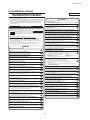
8. User’s manual
PSA012B751
Fresh Air DX Assembly (SAF-DX) Supplementary Information
This User’s manual addresses only a topic particular to this unit (more specifically, the
underlined section).
For any other contents, refer to the User’s manual attached to the outdoor unit.
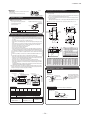
N HOW TO OPERATE
<WIRED REMOTE CONTROL>
Press
MODE button.
The range of operation mode is displayed according to the
model of indoor unit.
Fresh Air DX Assembly (SAF-DX), operation in dehumidifying
mode is not possible.
Setting to dehumidifying mode will perform operation in cooling
mode.
Every time the button is pressed, the display changes in the
following order dry © cool © fan © heat. (© auto)*
(The automatic operation can be selected in case of the heat
recovery system KXR only. The automatic operation cannot be
selected in case of heat pump system KX.)
• With auto operation,
heating and cooling is
automatically changed
depending on difference
between the setting
temperature and room
temperature.*
cooling operation
heating
operation
–3 (–2)
+3 (+2)
room setting
temperature *
( ) indicates the figure of SAF-DX.
* IN case of FDU-F
The setting temperature of the remote controller indicates
the outdoor temperature while operating thermostat
ON/OFF.
<WIRELESS REMOTE CONTROL>
OPERATION MODE select button (Dehumidifying operation is
prohibited for SAF-DX.)
Every time this button is pressed, Ndisplays switch as below
(AUTO)
(COOL)
(HEAT)
(FAN)
(DRY)
For the outdoor unit with Duct connected -High static pressure
outdoor air processing unit (FDU-F) and Fresh Air DX Assembly
(SAF-DX), operation in dehumidifying mode is not possible.
Setting to dehumidifying mode will perform operation in cooling
mode.
N HOW TO MAINTAIN
N Fresh Air DX Assembly (SAF-DX)
The air filter uses the filter of the total heat exchanger.
Follow the instructions in the User’s Manual for the total heat exchanger.
1
-
22 -
'11•SAF-T-161
9. Installation manual
PCH012D006
DUCT CONNECTED HIGH STATIC PRESSURE AIR
CONDITIONING UNIT INSTALLATION MANUAL
This manual is for the installation of an indoor unit.
For electrical wiring work (Indoor), refer to the electrical wiring work installation manual. For remote
controller installation, refer to the installation manual attached to a remote controller. For wireless kit
installation, refer to the installation manual attached to a wireless kit. For electrical wiring work
(Outdoor) and refrigerant pipe work installation for outdoor unit, refer to the installation manual
attached to an outdoor unit.
CAUTION
٨Perform earth wiring surely.
Do not connect the earth wiring to the gas pipe, water pipe, lightning rod and telephone earth wiring. Improper earth could
cause unit failure and electric shock due to a short circuit.
٨Earth leakage breaker must be installed.
If the earth leakage breaker is not installed, it can cause electric shocks.
٨Use the circuit breaker of correct capacity. Circuit breaker should be the one that disconnect all
poles under over current.
SAFETY PRECAUTIONS
Using the incorrect one could cause the system failure and fire.
٨Read the “SAFETY PRECAUTIONS” carefully first of all and then strictly follow it during the
installation work in order to protect yourself.
and CAUTION .
٨The precautionary items mentioned below are distinguished into two levels,
: Wrong installation would cause serious consequences such as injuries or death.
CAUTION : Wrong installation might cause serious consequences depending on circumstances.
Both mentions the important items to protect your health and safety so strictly follow them by
any means.
٨The meanings of “Marks” used here are as shown on the right:
Never do it under any circumstances.
٨Do not use any materials other than a fuse of correct capacity where a fuse should be used.
Connecting the circuit by wire or copper wire could cause unit failure and fire.
٨Do not install the indoor unit near the location where there is possibility of flammable gas leakages.
If the gas leaks and gathers around the unit, it could cause fire.
٨Do not install and use the unit where corrosive gas (such as sulfurous acid gas etc.) or flammable gas (such
as thinner, petroleum etc.) may be generated or accumulated, or volatile flammable substances are handled.
It could cause the corrosion of heat exchanger, breakage of plastic parts etc. And inflammable gas could cause fire.
٨Secure a space for installation, inspection and maintenance specified in the manual.
Always do it according to the instruction.
Insufficient space can result in accident such as personal injury due to falling from the installation place.
٨After completing the installation, do commissioning to confirm there are no abnormalities, and
explain to the customers about “SAFETY PRECAUTIONS”, correct operation method and
maintenance method (air filter cleaning, operation method and temperature setting method)
with user’s manual of this unit.
Ask your customers to keep this installation manual together with the user’s manual. Also, ask
them to hand over the user’s manual to the new user when the owner is changed.
٨Do not use the indoor unit at the place where water splashes such as laundry.
Indoor unit is not waterproof. It could cause electric shock and fire.
٨ Do not use the indoor unit for a special purpose such as food storage, cooling for precision
instrument, preservation of animals, plants, and a work of art.
It could cause the damage of the items.
٨ Do not install nor use the system near equipments which generate electromagnetic wave or high harmonics.
Equipments like inverter equipment, private power generator, high-frequency medical equipment, or telecommunication
equipment might influence the air conditioner and cause a malfunction and breakdown. Or the air conditioner might
influence medical equipments or telecommunication equipments, and obstruct their medical activity or cause jamming.
WARNING
٨ Do not install the remote controller at the direct sunlight.
٨Installation should be performed by the specialist.
It could cause breakdown or deformation of the remote controller.
If you install the unit by yourself, it may lead to serious trouble such as water leakage, electric shock, fire, and injury due to overturn
of the unit.
٨ Do not install the indoor unit at the place listed below.
· Places where flammable gas could leak.
· Places where carbon fiber, metal powder or any powder is floated.
· Place where the substances which affect the air conditioner are generated
such as sulfide gas, chloride gas, acid, alkali or ammonic atmospheres.
· Places exposed to oil mist or steam directly.
· On vehicles and ships
· Places where machinery which generates high harmonics is used.
٨Install the system correctly according to these installation manuals.
Improper installation may cause explosion, injury, water leakage, electric shock, and fire.
٨Checkthedensityreferedbythefoumula (accordancewithISO5149).
Ifthedensityexceedsthelimitdensity, pleaseconsultthe dealer andinstallatetheventilationsystem.
٨Use the genuine accessories and the specified parts for installation.
· Places where cosmetics or special sprays are
frequently used.
· Highly salted area such as beach.
· Heavy snow area
· Places where the system is affected by
smoke from a chimney.
· Altitude over 1000m
٨ Do not install the indoor unit in the locations listed below (Be sure to install the indoor unit
according to the installation manual for each model because each indoor unit has each limitation)
If parts unspecified by our company are used it could cause water leakage, electric shock, fire, and injury due to overturn of the unit.
٨Ventilate the working area well in case the refrigerant leaks during installation.
· Locations with any obstacles which can prevent inlet and outlet air of the unit
· Locations where vibration can be amplified due to insufficient strength of structure.
· Locations where the infrared receiver is exposed to the direct sunlight or the strong light beam. (in case of the
infrared specification unit)
· Locations where an equipment affected by high harmonics is placed. (TV set or radio receiver is placed within 5m)
· Locations where drainage cannot run off safely.
It can affect performance or function and etc..
If the refrigerant contacts the fire, toxic gas is produced.
٨Install the unit in a location that can hold heavy weight.
Improper installation may cause the unit to fall leading to accidents.
٨Install the unit properly in order to be able to withstand strong winds such as typhoons, and earthquakes.
Improper installation may cause the unit to fall leading to accidents.
٨ Do not put any valuables which will break down by getting wet under the air conditioner.
٨Do not mix air in to the cooling cycle on installation or removal of the air conditioner.
Condensation could drop when the relative humidity is higher than 80% or drain pipe is clogged, and it damages user’s belongings.
If air is mixed in, the pressure in the cooling cycle will rise abnormally and may cause explosion and injuries.
٨ Install the drain pipe to drain the water surely according to the installation manual.
٨Be sure to have the electrical wiring work done by qualified electrical installer, and use exclusive circuit.
Improper connection of the drain pipe may cause dropping water into room and damaging user’s belongings.
Power source with insufficient capacity and improper work can cause electric shock and fire.
٨ Be sure to perform air tightness test by pressurizing with nitrogen gas after completed refrigerant piping work.
If the density of refrigerant exceeds the limit in the event of refrigerant leakage in the small room, lack of oxygen can
occur, which can cause serious accidents.
٨Use specified wire for electrical wiring, fasten the wiring to the terminal securely, and hold the cable securely in
order not to apply unexpected stress on the terminal.
٨ For drain pipe installation, be sure to make descending slope of greater than 1/100, not to make traps,
and not to make air-bleeding.
Loose connections or hold could result in abnormal heat generation or fire.
٨Arrange the electrical wires in the control box properly to prevent them from rising. Fit the lid of the services
panel property.
Check if the drainage is correctly done during commissioning and ensure the space for inspection and maintenance.
٨ Ensure the insulation on the pipes for refrigeration circuit so as not to condense water.
Improper fitting may cause abnormal heat and fire.
Incomplete insulation could cause condensation and it would wet ceiling, floor, and any other valuables.
٨Check for refrigerant gas leakage after installation is completed.
٨ Pay extra attention, carrying the unit by hand.
If the refrigerant gas leaks into the house and comes in contact with a fan heater, a stove, or an oven, toxic gas is produced.
Carry the unit with 2 people if it is heavier than 20kg. Do not use the plastic straps but the grabbing place, moving the unit
by hand. Use protective gloves in order to avoid injury by the aluminum fin.
٨Use the specified pipe, flare nut, and tools for R410A.
٨ Make sure to dispose of the packaging material.
Using existing parts (R22) could cause the unit failure and serious accident due to explosion of the cooling cycle.
Leaving the materials may cause injury as metals like nail and woods are used in the package.
٨Tighten the flare nut according to the specified method by with torque wrench.
٨ Do not operate the system without the air filter.
If the flare nut were tightened with excess torque, it could cause burst and refrigerant leakage after a long period.
It may cause the breakdown of the system due to clogging of the heat exchanger.
٨Do not put the drainage pipe directly into drainage channels where poisonous gases such as sulfide gas can
occur.
٨ Do not touch any button with wet hands.
It could cause electric shock.
Poisonous gases will flow into the room through drainage pipe and seriously affect the user's health and safety. This can also
cause the corrosion of the indoor unit and a resultant unit failure or refrigerant leak.
٨ Do not touch the refrigerant piping with bare hands when in operation.
The pipe during operation would become very hot or cold according to the operating condition, and it could cause a burn or frostbite.
٨Connect the pipes for refrigeration circuit securely in installation work before compressor is operated.
٨ Do not clean up the air conditioner with water.
If the compressor is operated when the service valve is open without connecting the pipe, it could cause explosion and injuries due
to abnormal high pressure in the system.
It could cause electric shock.
٨ Do not turn off the power source immediately after stopping the operation.
٨Stop the compressor before removing the pipe after shutting the service valve on pump down work.
Be sure to wait for more than 5 minutes. Otherwise it could cause water leakage or breakdown.
If the pipe is removed when the compressor is in operation with the service valve open, air would be mixed in the refrigeration circuit
and it could cause explosion and injuries due to abnormal high pressure in the cooling cycle.
٨ Do not control the operation with the circuit breaker.
It could cause fire or water leakage. In addition, the fan may start operation unexpectedly and it may cause injury.
٨Only use prescribed optional parts. The installation must be carried out by the qualified installer.
If you install the system by yourself, it can cause serious trouble such as water leaks, electric shocks, fire.
٨Do not repair by yourself. And consult with the dealer about repair.
Improper repair may cause water leakage, electric shock or fire.
٨Consult the dealer or a specialist about removal of the air conditioner.
Improper installation may cause water leakage, electric shock or fire.
٨Turn off the power source during servicing or inspection work.
If the power is supplied during servicing or inspection work, it could cause electric shock and injury by the operating fan.
٨Shut off the power before electrical wiring work.
It could cause electric shock, unit failure and improper running.
-
23 -
'11•SAF-T-161
Control box
Important
Air outlet
Air outlet
Make sure to use the unit in combination with the total
heat exchanger.
Use the unit within the air flow range of ԙ.
Suction
ԚPreparation before installation
When the unit is installed,
this face becomes at the bottom.
ԘBefore installation
٨Install correctly according to the installation manual.
٨Confirm the following points:
Location of accessory (In the packing)
ޓ٤Unit type/Power supply specification
Documents
(Fixed with
ޓ٤Pipes/Wires/Small parts
adhesive tape.)
ޓ٤Accessory items
٨If suspension bolt becomes longer, do reinforcement of earthquake resistant.
ޓ٤For grid ceiling
ޓޓWhen the suspension bolt length is over 500mm, or the gap between the ceiling and roof
is over 700mm, apply earthquake resistant brace to the bolt.
٤In case the unit is hanged directly from the slab and is installed on the ceiling plane which
has enough strength.
ޓޓWhen suspension bolt length is over 1000mm, apply the earthquake resistant brace to the bolt.
٨Prepare four (4) sets of suspension bolt, nut and spring washer (M10) on site.
Suspension Bolt Location
Accessory
Accessory item
160
)
ct
O
L9
27
67
90
3 15
28 5
450
L2
270
L5
Exit duct
160
264
Code
A
B
C
D
E
F
G
L8
(D
uc
tO
.D
)
D
E
F
Bottom face of
hanging hardware)
L4
G
L1
Type
SAF-DX1000E6
SAF-DX800E6
SAF-DX500E6
SAF-DX350E6
SAF-DX250E6
L1
822
682
537
452
452
L2
710
570
425
340
340
L3
630
490
345
260
260
L4
250
320
212.5
170
170
L5
190
250
212.5
170
170
Item
Piping at refrigerant gas side
Piping at refrigerant liquid side
For natural draining
Power cable intake
Total heat exchanger wire intake
Communication cable intake
Hanging bolt
L6
L7
385
325
320
250
212. 5 212.5
170
170
170
170
L8
2-ø200
ø250
ø200
ø150
ø150
200
or more
Space for drain trap and
gradient of drain
[Hanging]
Hang the unit up.
Piping space
If the measurements between
the unit and the ceiling hole do
not match upon installation, it
may be adjusted with the long
holed installation tool.
Suspension bolt
Washer for M10
500
82
M10 nut
Unit
82
When the
conditions as
shown at left
cannot be met,
it may be
arranged as
shown at right.
Type
SAF-DXP10003
SAF-DXP8003
SAF-DXP5003
SAF-DXP3503
Spring washer for M10
100
Suction
(For service at both side and bottom faces)
A
870
730
585
500
Adjustment for horizontality
Air flow range
Air flow
range
(m3/h)
Resistance
in the unit
(Pa)
Lower limit
air flow
(m3/h)
Resistance
in the unit
(Pa)
Upper limit
air flow
(m3/h)
Resistance
in the unit
(Pa)
250
350
500
800
1000
25
66
66
66
66
200
280
400
640
800
38
45
45
45
45
300
420
600
960
1200
50
90
90
90
90
٤Either use a level vial, or adjust the level according to the method below.
٨Adjust so the bottom side of the unit will be leveled with the water surface as
illustrated below.
Pipe side
Pour water
Water
surface
Air conditions
0~5mm
Suction air temperature of indoor unit
Cooling
Heating
Upper limit 27˚C DB
Upper limit 27˚C DB
With outdoor temperature at 35˚C
Outdoor temperature lower than 20˚C WB
Upper limit 16.5˚C WB
With outdoor temperature at -5˚C
L9
ø250
ø250
ø200
ø150
ø150
ԛInstallation of indoor unit
Elevation is same as shown at left.
Access hole
(500×A)
400 or more
60
Air outlet
300 or more
100 or more 650 or more
Ceiling
220
180
Access hole Bottom
face 220
Plan view (Unit: mm)
Space required for installation and removal of duct
(Dimensions may be reduced at site as required.)
(Side service space)
A
337
Top
face
Installation
Elevation (Unit: mm)
Service space
L3
40
71
67
Control box
٨Make installation altitude over 2.5m.
Access hole
(450×450)
70
B
Space for installation and service
Air outlet
C
64
(D
u
Hanging bolt pitch
ԙSelection of installation location for the indoor unit
Slab
Exit duct
Suction duct
.D
For heat insulation of refrigerant pipe
ԘSelect the suitable areas to install the unit under approval of the user.
ޓAreas where the indoor unit can deliver hot and cold wind sufficiently. Suggest to the user
to use a circulator if the ceiling height is over 3m to avoid warm air being accumulated on
the ceiling.
Areas where there is enough space to install and service.
Areas where it can be drained properly. Areas where drain pipe descending slope can be
taken.
Areas where there is no obstruction of airflow on both air return grille and air supply port.
Areas where fire alarm will not be accidentally activated by the air conditioner.
Areas where the supply air does not short-circuit.
Areas where it is not influenced by draft air.
Areas not exposed to direct sunlight.
Areas where dew point is lower than around 28°C and relative humidity is lower than 80%.
This indoor unit is tested under the condition of JIS (Japan Industrial Standard) high humidity condition and confirmed there is no problem. However, there is some risk of condensation drop if the air conditioner is operated under the severer condition than mentioned
above.
If there is a possibility to use it under such a condition, attach additional insulation of 10 to
20mm thick for entire surface of indoor unit, refrigeration pipe and drain pipe.
Areas where TV and radio stays away more than 1m. (It could cause jamming and noise.)
Areas where any items which will be damaged by getting wet are not placed such as food,
table wares, server, or medical equipment under the unit.
Areas where there is no influence by the heat which cookware generates.
Areas where not exposed to oil mist, powder and/or steam directly such as above fryer.
Areas where lighting device such as fluorescent light or incandescent light doesn’t affect
the operation.
(A beam from lighting device sometimes affects the infrared receiver for the wireless remote
controller and the air conditioner might not work properly.) ԙCheck if the place where the air conditioner is installed can hold the weight of the unit. If it is
not able to hold, reinforce the structure with boards and beams strong enough to hold it. If the
strength is not enough, it could cause injury due to unit falling.
Plan view (Unit: mm)
18
40
1 pc.
※
SAF-DX250E6
SAF-DX350E6
SAF-DX500E6
SAF-DX800E6
SAF-DX1000E6
Suction duct
337
18
Type
L6
Hanging bolt pitch
Pipe insulation
Suction
Unit: mm
L7
362
373
Lower limit 10˚C DB
Outdoor temperature higher than -20˚C WB
Air temperature around
indoor unit
Vinyl hose
Let the pipe side be slightly sloped.
٤If the unit is not leveled, it may cause malfunctions or inoperation of the float switch.
Dew-point temperature
lower than 28˚C
For details of air conditions, refer to the technical data issued by us.
-
24 -
'11•SAF-T-161
ԞDrain pipe
ԜDuct Work
Caution
OA
٨Install the drain pipe according to the installation manual in order to drain properly.
Imperfection in draining may cause flood indoors and wetting the household goods, etc.
٨Do not put the drain pipe directly into the ditch where toxic gas such as sulfur, the other harmful and
inflammable gas is generated. Toxic gas would flow into the room and it would cause serious
damage to user’s health and safety (some poisoning or deficiency of oxygen). In addition, it may
cause corrosion of heat exchanger and bad smell.
٨Connect the pipe securely to avoid water leakage from the joint.
٨Insulate the pipe properly to avoid condensation drop.
٨Check if the water can flow out properly from both the drain outlet on the indoor unit and the end
of the drain pipe after installation.
٨Make sure to make descending slope of greater than 1/100 and do not make up-down bend and/or trap
in the midway. In addition, do not put air vent on the drain pipe. Check if water is drained out properly from
the pipe during commissioning. Also, keep sufficient space for inspection and maintenance.
RA
EA
SA
Humidifier
Ceiling
surface
Total heat exchanger
Suction inlet with humidifier
(with air filter)
Direct expansion
coil kit
Access hole
(450□)
Air outlet
ԘNo air filter is attached to the main unit of air conditioner. Assemble an air filter in the suction
grill for convenience of cleaning.
ԙSelect appropriate location and form for the air outlet to distribute air throughout the room.
Moreover, the air outlet should be able to adjust the air flow volume.
ԚAn access hole must be provided at the ceiling. It is indispensable to maintain electrical
equipment, motor and functional items, and to wash the heat exchanger.
ԛDuct must be heat-insulated to prevent dewing. Necessary thickness of insulator is 65 mm
(JIS A9501).
Work procedure
1. Make sure to insert the drain hose (the end mode of soft PVC) to the end of the step part of
drain socket.
Attach the hose clamp to the drain hose around 10mm from the end, and fasten the screw
within 5mm left to the nut.
ޓ٨Do not apply adhesives on this end.
ޓ٨Do not use acetone-based adhesives to connect to the drain socket.
ԝRefrigerant pipe
VP-25
(Prepare on site)
Caution
VP-20
(Prepare on site)
٨Use the new refrigerant pipe.
Pipe cover (big)
(For insulation) (Accessory)
ޓWhen re-using the existing pipe system for R22 or R407C, pay attention to the following items.
ޓChange the flare nuts with the attached ones (JIS category 2), and reprocess the flare parts.
ޓDo not use thin-walled pipes.
Drain socket
٨Use phosphorus deoxidized copper alloy seamless pipe (C1220T specified in JIS H3300) for refrigeration pipe installation.
ޓIn addition, make sure there is no damage both inside and outside of the pipe, and no harmful
substances such as sulfur, oxide, dust or a contaminant stuck on the pipes.
٨Do not use any refrigerant other than R410A.
Stage difflernce part
Joint for VP-20
(Prepare on site)
Unit
Drain hose
Drain socket
Drain hose
(Accessory)
Clamp (Accessory)
(No adhesive allowed)
Pipe cover (For insulation)
(Prepare on site)
Pipe cover (small)
(For insulation) (Accessory)
ޓUsing other refrigerant except R410A (R22 etc.) may degrade inside refrigeration oil. And air getting into
refrigeration circuit may cause over-pressure and resultant it may result in bursting, etc.
٨Store the copper pipes indoors and seal the both end of them until they are brazed in order to avoid any dust, dirt or
water getting into pipe. Otherwise it will cause degradation of refrigeration oil and compressor breakdown, etc.
٨Use special tools for R410 refrigerant.
Fasten the screw within 5 mm left to the nut.
Hose clamp
Drain socket
Drain hose
Piping work
Refrigerant pipe
250mm
(Section where attached
in a straight line)
Metal plate
When conducting piping work, make sure to allow the pipes
to be aligned in a straight line for at least 250 mm, as shown
in the left illustration. (This is necessary for the drain pump
to function)
2. Prepare a joint for connecting VP-20 pipe, adhere and connect the joint to the drain hose
(the end made of rigid PVC), and adhere and connect VP-20 pipe (prepare on site).
̪As for drain pipe, apply VP-20 made of rigid PVC which is on the market.
٨When installing drain pipe, use VP-20 for the pipe goes up the closest to the unit, and
VP-25 or higher number product for farther pipes.
٨Make sure that the adhesive will not get into the supplied drain hose.
It may cause the flexible part broken after the adhesive is dried up and gets rigid.
٨The flexible drain hose is intended to absorb a small difference at installation of the unit
or drain pipes. Intentional bending, expanding may cause the flexible hose broken and
water leakage.
Work procedure
1. Remove the flare nut and blind flanges on the pipe of the indoor unit.
̪Make sure to loosen the flare nut with holding the nut on pipe side with a spanner and giving torque
to the nut with another spanner in order to avoid unexpected stress to the copper pipe, and then
remove them.
(Gas may come out at this time, but it is not abnormal.)
٨Pay attention whether the flare nut pops out. (as the indoor unit is sometimes pressured.)
2. Make a flare on liquid pipe and gas pipe, and connect the refrigeration pipes on the indoor unit.
̪Bend the pipe with as big radius as possible and do not bend the pipe repeatedly. In addition,
do not twist and crush the pipes.
̪Do a flare connection as follows:
٨Make sure to loosen the flare nut with holding the nut on pipe side with a spanner and giving
torque to the nut with another spanner in order to avoid unexpected stress to the copper
pipe, and then remove them.
٨When fastening the flare nut, align the refrigeration pipe with the center of flare nut, screw
the nut for 3-4 times by hand and then tighten it by spanner with the specified torque
mentioned in the table below. Make sure to hold the pipe on the indoor unit securely by a
spanner when tightening the nut in order to avoid unexpected stress on the copper pipe.
3. Cover the flare connection part of the indoor unit with attached insulation material after a gas
leakage inspection, and tighten both ends with attached straps.
٨Make sure to insulate both gas pipes and liquid pipes completely.
̪Incomplete insulation may cause dew condensation or water dropping.
4. Refrigerant is charged in the outdoor unit.
As for the additional refrigerant charge for the indoor unit and piping, refer to the installation
manual attached to the outdoor unit.
3. Make sure to make descending slope of greater than 1/100 and do not make up-down bend
and/or trap in the midway.
٨Pay attention not to give stress on the pipe on the indoor unit side, and support and fix the
pipe as close place to the unit as possible when connecting the drain pipe.
٨Do not set up air vent.
1.5m~2m Supporting metal
SAF-DX800E6
SAF-DX500E6
SAF-DX350E6
SAF-DX250E6
Liquid pipe
Gas pipe
Liquid pipe
Gas pipe
Liquid pipe
Gas pipe
Liquid pipe
Gas pipe
Liquid pipe
Gas pipe
φ 9.52
φ 15.88
φ 6.35
φ 12.7
φ 6.35
φ 12.7
φ 6.35
φ9.52
φ 6.35
φ9.52
Flare connection
Flare connection
Flare connection
Flare connection
Flare connection
Flare connection
Flare connection
Flare connection
Flare connection
Flare connection
Strap (Accessory)
No bump
Air vent
Trapped air will
generate noises.
No trap
Not touching the water
Insulation material
Descending slope greater than 1/100
٨When sharing a drain pipe for more than
one unit, lay the main pipe 100mm
below the drain outlet of the unit. In
addition, select VP-30 or bigger size for
main drain pipe.
Type
SAF-DX1000E6
10mm
Pipe cover (Accessory)
The thickness of insulation should be 20mm or more.
-
As wide as possible
(about100mm)
VP-30 or bigger
Descending slope greater than 1/100
4. Insulate the drain pipe.
٨Be sure to insulate the drain socket and rigid PVC pipe installed indoors otherwise it may
cause dew condensation and water leakage.
̪After drainage test implementation, cover the drain socket part with pipe cover (small size), then
use the pipe cover (big size) to cover the pipe cover (small size), clamps and part of the drain
hose, and fix and wrap it with tapes to wrap and make joint part gapless.
25 -
'11•SAF-T-161
ԞDrain pipe (continued)
ԠCheck list after installation
Drain up
٨Check the following items after all installation work completed.
٨The position for drain pipe outlet can be raised up to 600mm above the ceiling. Use elbows for
installation to avoid obstacles inside ceiling. If the horizontal drain pipe is too long before vertical pipe,
the backflow of water will increase when the unit is stopped, and it may cause overflow of water from the
drain pan on the indoor unit. In order to avoid overflow, keep the horizontal pipe length and offset of the
pipe within the limit shown in the figure below.
600
Maximum local
drain up dimension
290~325mm
Drain hose
Check if
Expected trouble
The indoor and outdoor units are fixed securely?
Falling, vibration, noise
Inspection for leakage is done?
Insufficient capacity
Insulation work is properly done?
Water leakage
Does the air flow falls within the range of ?
It cannot cool or warm
Water is drained properly?
Water leakage
Check
Supply voltage is same as mentioned in the model name plate? PCB burnt out, not working at all
Right overhead
Joint for VP20 (local procurement)
Otherwise, the construction point makes it same as drain pipe construction.
There is mis-wiring or mis-connection of piping?
PCB burnt out, not working at all
Earth wiring is connected properly?
Electric shock
Cable size comply with specified size?
PCB burnt out, not working at all
Any obstacle blocks airflow on air inlet and outlet?
Insufficient capacity
٨After completing the check, test-run the unit according to the procedure described in the
Outdoor Unit Installation Manual.
Drain test
1. Conduct a drain test after completion of the electrical work.
2. During the trail, make sure that drain flows properly through the piping and that no water
leaks from connections.
3. In case of a new building, conduct the test before it is furnished with the ceiling.
4. Be sure to conduct this test even when the unit is installed in the heating season.
Procedures
1. Supply about 1000 cc of water to the unit through the air outlet by using a feed water pump.
2. Check the drain while cooling operation.
Insert water supply hose
for 50mm to
supply water.
(Insert hose facing
toward bottom.)
Remove grommet
Make sure to Install
it back after test.
Attached drain hose clamp
Pour water into a convex joint
Drain
Main
piping
unit
Drain situation can be checked with transparent socket.
If the electrical work has not been completed, connect a convex
joint in the drain pipe connection to provide a water inlet.
Then, check if water leaks from the piping system and that
drain flows through the drain pipe normally.
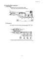
ԟWiring-out position and wiring connection
٨Electrical installation work must be performed according to the installation manual by an
electrical installation service provider qualified by a power provider of the country, and be
executed according to the technical standards and other regulations applicable to electrical
installation in the country.
Be sure to use an exclusive circuit.
٨Use specified cord, fasten the wiring to the terminal securely, and hold the cord securely in
order not to apply unexpected stress on the terminal.
٨Do not put both power source line and signal line on the same route. It may cause miscommunication and malfunction.
٨Be sure to do D type earth work.
٨For the details of electrical wiring work, see attached instruction manual for electrical wiring
work.
1. Remove a lid of the control box (2 screws).
2. Hold each wiring inside the unit and fasten them to terminal block securely.
3. Fix the wiring with clamps.
4. Install the removed parts back to original place.
3
Indoor unit power cable.
Communication
terminal block
Total heat exchanger cable
Band for driving
electric power cable
Super Link cable
X Y A B
Total heat exchanger
terminal block
1 2 3 4 5 6
1
2
Power supply terminal block
Do not connect the power
supply for the total heat
exchanger to the power
supply terminal block.
Band for light electric cable
Remote control cable
For further details, refer to the attached Electric Wiring Work Manual (see next page).
-
PCH012D006
26 -
'11•SAF-T-161
ELECTRIC WIRING WORK INSTRUCTION
Electrical wiring work must be performed by an electrician qualified by a local power provider according to
the electrical installation technical standards and interior wiring regulations applicable to the installation site.
Security instructions
٨ Read the “SAFETY PRECAUTIONS” carefully first of all and then strictly follow it during the
installation work in order to protect yourself.
٨ The precautionary items mentioned below are distinguished into two levels,
and CAUTION .
: Wrong installation would cause serious consequences such as injuries or death.
CAUTION : Wrong installation might cause serious consequences depending on circumstances.
Both mentions the important items to protect your health and safety so strictly follow
them by any means.
٨ The meanings of “Marks” used here are as shown on the right:
Never do it under any circumstances.
Always do it according to the instruction.
٨ Accord with following items. Otherwise, there will be the risks of electric shock and
fire caused by overheating or short circuit.
WARNING
٨Be sure to have the electrical wiring work done by qualified electrical installer,
and use exclusive circuit.
Power source with insufficient capacity and improper work can cause electric shock and fire.
PCH012D007
ԘPower supply – Wire connection between the indoor/outdoor unit and the total heat exchanger (continued)
٨Electrical wiring work must be performed by an electlician an qualified by a local power
provider. These wiring specifications are determined on the assumption that the following
instructions are observed:
Ԙ Do not use cords other than copper ones.
Do not use any supply line lighter than one specified in parentheses for each type below.
-braided cord (code designation 60245 IEC 51), if allowed in the relevant part 2;
-ordinary tough rubber sheathed cord (code designation 60245 IEC 53);
-flat twin tinsel cord (code designation 60227 IEC 41);
-ordinary polyvinyl chloride sheathed cord (code designation 60227 IEC 53);
ԙ Provide a separate power outlet for each outdoor or indoor unit.
Ԛ All indoor units grouped in one system must have power source that can be turned on or off simultaneously.
ԛ Pay extra attention so as not to confuse signal line and power source line connection, because an error in their connection can be
burn all the boards at once.
٨Connection of the line ("Between indoor and outdoor unit", Earth and Remote controller)
Ԙ Remove lid of control box before connect the above lines, and connect the lines to terminal block according to number pointed on
label of terminal block.
In addition, pay enough attention to confirm the number to lines, because there is electrical polarity except earth line.
Furthermore, connect earth line to earth position of terminal block of power source.
ԙ Install earth leakage breaker on power source line. In addition, select the type of breaker for inverter circuit as earth leakage breaker.
Ԛ If the function of selected earth leakage breaker is only for earth-fault protection, hand switch (switch itself and type "B" fuse) or circuit
breaker is required in series with the earth leakage breaker.
ԛ Install isolator or disconnect switch on the power supply wiring in accordance with the local codes and regulations.
The isolator should be set in the box with key to prevent touching by another person when servicing.
Cabling system diagram (Outdoor/indoor unit connection procedure)
٨Use specified wire for electrical wiring, fasten the wiring to the terminal securely,
and hold the cable securely in order not to apply unexpected stress on the terminal.
㿈 㿉
㪙
䂾
Earth leakage breaker
٨Arrange the electrical wires in the control box properly to prevent them from
rising. Fit the lid of the services panel property.
Specification of each line
Power source line
2.0~3.5mm2
Signal line (Shielded cord) 0.75~1.25mm2
Remote controller line
0.3~1.25mm2
Outdoor unit
Power source
Loose connections or hold could result in abnormal heat generation or fire.
Signal line (between indoor
and outdoor units)
Circuit breaker
Use shielded cord for a signal line and connect “earth
(signal line)” at all the indoor units and outdoor units.
Improper fitting may cause abnormal heat and fire.
٨Use the genuine optional parts. And installation should be performed by a specialist.
If you install the unit by yourself, it could cause water leakage, electric shock and fire.
㿓㩷
٨Do not repair by yourself. And consult with the dealer about repair.
㿕㩷
Improper repair may cause water leakage, electric shock or fire.
㩷 㿉
㿈
㩷 Indoor unit1
㿟㩷 㿠
㪰 Remote
䂾
controller line
Earth
٨Consult the dealer or a specialist about removal of the air conditioner.
Improper installation may cause water leakage, electric shock or fire.
٨Turn off the power source during servicing or inspection work.
㿓
㩷
㿕
㩷 㿉
㿈㩷
Indoor unit2
Signal line
(between indoor unit)
㿟㩷 㿠
Remote
controller line
Earth
㿟 㩷㿠
㿟 㩷㿠
Remote controller
㩷
Remote controller
㩷
٨Perform earth wiring surely.
Indoor unit
Do not connect the earth wiring to the gas pipe, water pipe, lightning rod and telephone earth wiring.
Improper earth could cause unit failure and electric shock due to a short circuit.
٨Make sure to connect wires so that the total heat exchanger is operated
synchronized with the operation of SAF.
Do not operate from the remote controller of total heat exchanger.
TB2
6
5
AC200V
XR1
1
CAUTION
2
4
It could cause electric shock, unit failure and improper running.
3
٨Shut off the power before electrical wiring work.
52X1
If the power is supplied during servicing or inspection work, it could cause electric shock and injury by
the operating fan.
51X1
Wire connection to total heat exchanger
Error output
External operation input
Humidifier
٨For details, refer to the installation manual and the instruction manual of
total heat exchanger.
External operation input
Total heat exchanger
Total heat exchanger
Power source line specification
٨Earth leakage breaker must be installed.
Wiring specification
If the earth leakage breaker is not installed, it can cause electric shocks.
٨Make sure to install earth leakage breaker on power source line.
(countermeasure thing to high harmonics.)
Unit type
Absence of breaker could cause electric shock.
Earth leakage
breaker
SAF-DX250E6
350E6
500E6 15A 30mA 0.1sec
800E6
1000E6
٨Use the circuit breaker of correct capacity. Circuit breaker should be the one
that disconnect all poles under over current.
Using the incorrect one could cause the system failure and fire.
٨Do not use any materials other than a fuse of correct capacity where a fuse
should be used.
Circuit breaker
Overcurrent
protector rated
capacity
Switch
breaker
30A
15A
Wiring size
Power
source
line
Wire
length
Signal line
2
2.0mm 2000m
0.75~2
×2
1.25mm ×2
Remote
controller
line
2
0.3mm
×2cores
Earth
line
2
2.0mm
Note (1) The cord distances are calculated with a voltage drop of 2%. If the distance should exceed the
above data, review the cord thickness to use in accordance with your extension cord regulations.
(2) When total extension of remote controller line is more than 100m, change the size of cord
according to "Ԛ Remote Control, Wiring and functions".
Connecting the circuit by wire or copper wire could cause unit failure and fire.
٨Use power source line of correct capacity.
Using incorrect capacity one could cause electric leak, abnormal heat generation and fire.
In case of Heat recovery 3-pipe systems
٨Do not mingle solid cord and stranded cord on power source and signal side
terminal block.
Branching controller of heat recovery 3-pipe systems wiring
In addition, do not mingle difference capacity solid or stranded cord.
Inappropriate cord setting could cause loosing screw on terminal block, bad electrical contact, smoke and fire.
٨When this unit is used as a "Heat Recovery 3-pipe Systems", refer to the installation
manual of a branching controller (option).
٨Do not turn off the power source immediately after stopping the operation.
Be sure to wait for more than 5 minutes. Otherwise it could cause water leakage or breakdown.
٨Install an over-current and earth leakage breaker (threshold current: 30mA) specified for each
unit without fail.
٨ Provide a dedicated branching circuit and never share a branching circuit with other
equipment. If shared, disconnection at the circuit breaker may occur, which can cause
secondary damage.
٨Set earth of D-type.
٨Connection of a cable beyond 3.5 mm 2 is not permitted. When cables of over 5.5 mm 2 are in
use, provide a dedicated pull box to take a branch to an indoor unit.
٨Keep "remote controller line" and "power source line" away from each other on constructing of
unit outside.
٨Run the lines (power source, remote controller and "between indoor and outdoor unit") upper
ceiling through iron pipe or other tube protection to avoid the damage by mouse and so on.
٨Do not add cord in the middle of line (of indoor power source, remote controller and signal) route
on outside of unit. If connecting point is flooded, it could cause problem as for electric or
communication.
(In the case that it is necessary to set connecting point on the signal line way, perform
thorough waterproof measurement.)
٨Do not connect the power source line [220V/240V/380V/415V] to signal side terminal block.
Otherwise, it could cause failure.
٨Screw the line to terminal block without any looseness, certainly.
٨Do not turn on the switch of power source, before all of line work is done.
1. Remove a lid of the control box (2 screws).
2. Hold each wiring inside the unit and fasten
them to terminal block securely.
3. Fix the wiring with clamps.
4. Install the removed parts back to original place.
2
Indoor unit
power cable.
1
ԘPower supply – Wire connection between the indoor/outdoor unit and the total heat exchanger
TB1
1 2 3 4 5 6
٨Electrical installation work must be performed
according to the installation manual by an
Power supply
electrical installation service provider qualified terminal block
Do not connect the
by a power provider of the country, and be
power supply for the
executed according to the technical standards total heat exchanger
to the power supply
and other regulations applicable to electrical
terminal block.
installation in the country.
Be sure to use an exclusive circuit.
٨Use specified cord, fasten the wiring to the terminal
securely, and hold the cord securely in order not to Total heat exchanger
terminal block
apply unexpected stress on the terminal.
٨Do not put both power source line and signal line
on the same route. It may cause miscommunication and malfunction.
٨Be sure to do D type earth work.
Communication
٨For the details of electrical wiring work, see attached
terminal block
instruction manual for electrical wiring work.
TB2
Total heat
exchanger
cable
Band for
driving
electric
power cable
Super Link cable
X Y A B
It could cause fire or water leakage. In addition, the fan may start operation unexpectedly and it may
cause injury.
3
ԙWiring-out position and wiring connection
٨Do not control the operation with the circuit breaker.
Band for
light electric
cable
TB2
Remote control cable
For further details, refer to the attached
Electric Wiring Work Manual (PCH012D005).
ԚAddress setting
Address setting is done by (1) Manual address setting or (2) Automatic address setting.
In the case of (2) "Automatic address setting", it is possible to change address setting by wired
remote controller after once complete setting.
As for details of setting procedure, refer to instructions attached to the outdoor unit for details.
-
27 -
'11•SAF-T-161
ԛRemote Control, Wiring and functions
ԜTrial operation (continued)
٨Do not install it on the following places.
2. Ending a cooling test run.
Pressing the
button, the
(TEMP) button or
(MODE) button will end a
cooling test run. (Cooling test run will end after 30 minutes pass.)
“
” shown on the screen will go off.
(1) Place exposed to direct sunlight
(2) Places near heat devices
(3) High humidity places
(4) Hot surface or cold surface enough to generate condensation
(5) Place exposed to oil mist or steam directly.
(6) Uneven surface
Installation and wiring of remote controller
Checking operation data
ԘInstall remote controller referring to the attached manual.
ԙWiring of remote controller should use 0.3mm2 x2 core wires or cables.
The insulation thickness is 1mm or more. (on-site configuration)
ԚMaximum prolongation of remote control wiring is 600 m.
Operation data can be checked with remote control unit operation.
1. Press the
button.
The display change “
”
2. Press the
(SET) button while “
” is displayed.
When only one indoor unit is connected to remote controller, “
” is displayed
(blinking indication during data loading).
Next, operation data of the indoor unit will be displayed. Skip to step 7.
4. When plural indoor units is connected, the smallest address number of indoor unit among all
connected indoor unit is displayed.
[Example]:
“
” (blinking 1 seconds)
“
” blinking.
5. Select the indoor unit number you would like to have data displayed with the
button.
6. Determine the indoor unit number with the
(SET) button.
(The indoor unit number changes from blinking indication to continuous indication)
“
” (The address of selected indoor unit is blinking for 2 seconds.)
If the prolongation is over 100m, change to the size below.
2
But, wiring in the remote controller case should be under 0.5mm . Change the wire size outside of the case according to
wire connecting. Waterproof treatment is necessary at the wire connecting section. Be careful about contact failure.
100-200m ...................0.5mm2×2 core
Under 400m.....................1.25mm2 × 2 core
Under 300m................0.75mm2 × 2 core
Under 500m.....................2.0mm2 × 2 core
ԛAvoid using multi-core cables to prevent malfunction.
ԜKeep remote controller line away from earth (frame or any metal of building).
ԝMake sure to connect remote controller line to the remote controller and terminal block of indoor unit. (No polarity)
Control plural indoor units by a single remote controller
ԘA remote controller can control plural indoor units (up to 16)
In above setting, all plural indoor units will operate under same mode and temperature setting.
ԙConnect all indoor units with 2 core remote controller line for group control.
ԚUse the function of manual address setting to set the indoor and outdoor address number.
“
” (A blinking indication appears while data loaded.)
Next, the operation data of the indoor unit is indicated.
7. Upon operation of the
button, the current operation data is displayed in order from
data number 01.
The items displayed are in the following table
̪Depending on models, the items that do not have corresponding data are not displayed.
button, which allows you to
8. To display the data of a different indoor unit, press the
go back to the indoor unit selection screen.
9. Pressing the
button will stop displaying data.
Pressing the
(RESET) button during remote control unit operation will undo your last
operation and allow you to go back to the previous screen.
٧If two (2) remote controllers are connected to one (1) inside unit, only the master controller is available
for trial operation and confirmation of operation data. (The slave remote controller is not available.)
٤Do not forget to set the number for the outdoor units.
ԛAs shown in the following figure, the remote control can be used to control multiple outdoor units.
ԜOne remote control is able to perform group control for multiple units (maximum 16 units).
٤Use the rotary SW1 and SW2 provided on the indoor unit PCB (Printed circuit board) to set unique remote control
communication address avoiding duplication.
After a unit is energized, it is possible
to display an indoor unit address by
pressing AIR CON NO button on
the remote control unit.
Press the
or
button to make
sure that all indoor units connected
are displayed in order.
Outdoor unit
No.01 㩷
Outdoor unit㩷
No.02 㩷
㿈 㿉
㿈㩷 㿉㩷
Indoor unit 㩷 㿈 㿉
Outdoor No.01 㩷
Indoor No.01 㩷 㿟 㿠
Indoor unit 㩷 㿈 㿉
Outdoor No.02 㩷
Indoor No.04 㩷 㿟 㿠
Indoor unit 㩷 㿈 㿉
Outdoor No.01
Indoor No.02 㿟 㿠
Indoor unit 㩷 㿈 㿉
Outdoor No.02 㩷
Indoor No.05㩷 㿟 㿠
01
02
03
04
05
06
07
08
09
10
11
12
21
22
23
24
25
26
27
28
29
30
31
32
33
34
35
36
37
38
39
Indoor unit 㩷 㿈 㿉
Outdoor No.02 㩷
Indoor No.06㩷 㿟 㿠
Indoor unit 㩷 㿈 㿉
Outdoor No.01 㩷
Indoor No.03㩷 㿟 㿠
㿟 㩷㿠
Number
Remote controller line
(No polarity)
Action time㩷
Confirming method of indoor units
㩷
When indoor unit address number is displayed on
remote controller, pushing the
(MODE)
button to make the indoor unit with that number
blow air (Display example:"
").
Push the
(MODE) button again to stop the
operation.
However, this operation is invalid on the
air-conditioning running.
Indoor unit
㿟㩷 㿠㩷
Remote controller line
(No polarity)
㿟㩷 㿠㩷
㿟㩷 㿠㩷
Action time
SW1” Master”
Action time
SW1” Slave”
Switch
Setting
Master
Wired remote controller: SW1
Wireless kit: SW1-2
Slave
Contents
Master remote
controller
Slave remote
controller
Master/slave setting when more than one remote control unit are used
A maximum of two remote control units can be connected to one indoor unit (or one group of indoor units.)
Latest "function setting" is superior than previous one.
Acceptable combination is "two (2) wired remote controllers", "one (1) wired remote controller and one (1)
wireless kit" or "two (2) wireless kits".
Set SW1 to "Slave" for the slave remote control unit. It was factory set to "Master" for shipment.
Note:The setting "Remote control unit sensor enabled" is only selectable with the master remote control unit
in the position where you want to check room temperature.
(Operation Mode)
(Set Temperature)
(Return Air Temperature)
(Remote Controller Thermistor Temperature)
(Indoor Unit Heat Exchanger Thermistor / U Bend)
(Indoor Unit Heat Exchanger Thermistor /Capillary)
(Indoor Unit Heat Exchanger Thermistor /Gas Header)
(Indoor Unit Fan Speed)
(Frequency Requirements)
(Response Frequency)
(Pulse of Indoor Unit Expansion Valve)
(Total Running Hours of The Indoor Unit)
(Outdoor Air Temperature)
(Outdoor Unit Heat Exchanger Thermistor)
(Outdoor Unit Heat Exchanger Thermistor)
(Compressor Frequency)
(High Pressure)
(Low Pressure)
(Discharge Pipe Temperature)
(Comp Bottom Temperature)
(Current)
(Target Super Heat)
(Super Heat)
(Discharge Pipe Super Heat)
(Protection State No. of The Compressor)
(Outdoor Unit Fan Speed)
(63H1 On/Off)
(Defrost Control On/Off)
(Total Running Hours of The Compressor)
(Pulse of The Outdoor Unit Expansion Valve EEVC)
(Pulse of The Outdoor Unit Expansion Valve EEVH)
̪Depending on outdoor unit model, there are data not shown.
Trail operation of drain pump
Drain pump operation from remote control unit is possible. Operate a remote control unit by
following the steps described below.
1. To start a forced drain pump operation.
ԘPress the TEST button for three seconds or longer.
The display will change “
”
ԙPress the
button once and cause “
” to be displayed.
ԚWhen the
(SET) button is pressed, a drain pump operation will start.
Display: “
”
2. To cancel a drain pump operation.
ԘIf either
(SET) or
button is pressed, a forced drain pump operation will
stop. The air conditioning system will become OFF.
ԜTrial operation
The method of trial cooling operation
Operate the remote control unit as follows.
1. Starting a cooling test run.
ԘStart the system by pressing the
button.
ԙSelect “ (Cool)” with the
(MODE) button.
ԚPress the TEST button for 3 seconds or longer.
The screen display will switch to: “ ”
ԛWhen the
(SET) button is pressed while “ run will start.
The screen display will switch to “
”.
Data Item
” is indicated, a cooling test
٧If two (2) remote controllers are connected to one (1) inside unit, only the master controller is available
for trial operation and confirmation of operation data. (The slave remote controller is not available.)
-
28 -
'11•SAF-T-161
ԝFunction Setting by Remote Controller
The functional setting
The initial function setting for typical using is performed automatically for a remote control unit and
an indoor unit by the door unit connected, when remote controller and inside unit are connected.
As long as they are used in a typical manner, there wiil be no need to change the initial settings.
If you would like to change the initial setting marked “ ”, set your desired setting as for the
selected item.
The procedure of functional setting is shown as the following diagram.
As for detail of setting, refer to the installation manual of remote controller.
[Flow of function setting]
Start
: While indoor unit do not operate, press “
” (SET) and “
” (MODE) button for
3 seconds at the same time.
Finalize : Press “
” (SET) button.
Reset : Press “
” (RESET) button.
Select : Press
button.
End
: Press
button.
It is possible to finish above setting on the way, and unfinished change of setting is unavailable.
“ ” : Initial settings
“ ” : Automatic criterion
As for detail, refer to the installation manual of remote controller.
During air-conditioner stopping push
(SET) +
(MODE) button
simultaneously for 3 seconds
Consult the technical data etc. for each control details
Only when plural indoor units are connected
Indoor No. selection
Function
(Note3)
setting
02
(Indoor unit function)
(Remote controller function)
Function
setting
01
Record and save the
setting
(Note2) This is used to change the minimum aperture of expansion
valve during heating.
When you use at 50Hz area
When you use at 60Hz area
02
03
03
Temperature setting button is not working
04
If to change re-set with other indoor
unit, push AIRCON NO.
button, and indoor selection indication
(for example: I/U 000) is set back.
The filter sign is indicated after running for 180 hours.
The filter sign is indicated after running for 600 hours.
The filter sign is indicated after running for 1000 hours.
The filter sign is indicated after running for 1000 hours,
then it will be stopped by compulsion after 24 hours.
04
Mode button is not working
This function is not used. Do not change the setting.
05
On/Off button is not working
05
This function is not used. Do not change the setting.
06
This function is not used. Do not change the setting.
07
06
07
Make permission/prohibition control of function be in effect.
08
With the VRF series, it is used to stop all indoor units connected with
the same outdoor unit immediately.
When stop signal is inputed from remote on-off terminal "CNT-6",
all indoor units are stopped immediately.
Timer button is not working
09
Remote thermistor is not working.
Remote thermistor is working.
Remote thermistor is working, and to be set for producing +3.0°C increase in temperature.
Remote thermistor is working, and to be set for producing +2.0°C increase in temperature.
Remote thermistor is working, and to be set for producing +1.0°C increase in temperature.
Remote thermistor is working, and to be set for producing -1.0°C increase in temperature.
Remote thermistor is working, and to be set for producing -2.0°C increase in temperature.
Remote thermistor is working, and to be set for producing -3.0°C increase in temperature.
(Note2)
08
(Note2)
09
10
11
10
When heating thermostat is off, to be operated with low air flow.
When heating thermostat is off, to be operated with set air flow.
(Note1)
When heating thermostat is off, to be operated intermittently.
When heating thermostat is off, the fan stops.
When the remote thermistor is working, "FAN OFF" is set automatically.
Do not set when the indoor unit's thermistor is working.
12
If you change the range of set temperature, the indication of set temperature will vary
following the control.If you change the range of set temperature, the indication of set
temperature will not vary following the control, and keep the set temperature.
11
Change of indoor heat exchanger temperature to start frost prevention control.
12
Working only with the single split series.
To control frost prevention, the indoor fan tap is raised.
13
This function is not used. Do not change the setting.
13
14
Drain pump is on during cooling and dry.
Drain pump is on during cooling, dry and heating.
Drain pump is on during cooling, dry, heating and fan.
Drain pump is on during cooling, dry and fan.
This function is not used. Do not change the setting.
15
14
After cooling is stopped, the fan does not perform extra operation.
After cooling is stopped, the fan perform extra operation for half an hour.
After cooling is stopped, the fan perform extra operation for an hour.
After cooling is stopped, the fan perform extra operation for six hours.
This function is not used. Do not change the setting.
16
If you input into the indoor printed circuit board CNT from outside, the indoor device will
be operated independently following the input from outside.
If you input into indoor printed circuit board CNT from outside, All units which share the
same one remote control network work following the input from outside.
15
After heating is stopped or heating thermostat is off, the fan does not perform extra operation.
After heating is stopped or heating thermostat is off,the fan perform extra operation for half an hour.
After heating is stopped or heating thermostat is off,the fan perform extra operation for two hours.
After heating is stopped or heating thermostat is off, the fan perform extra operation for six hours.
17
18
In normal working indication, indoor unit temperature is indicated instead of airflow.
(Only the master remote control can be indicated. )
16
During heating is stopped or heating thermostat is off, the fan perform intermittent operation
for five minutes after twenty minutes' off with low airflow.
During heating is stopped or heating thermostat is off, the fan perform intermittent operation
for five minutes after five minutes' off with low airflow.
Heating preparation indication should not be indicated.
19
Temperature indication is by degree C
Temperature indication is by degree F
17 External device control
Pressure control – Standard
Pressure control – Selectable
ON/OFF button
(finished)
-
29 -
By setting of SW7-4 (Note3)
'11•SAF-T-161
ԝFunction Setting by Remote Controller
Note 1
Auto operation control
Note 2
Outlet temperature control
Note 3
Pressure control OFF
•If the remote control operation switch is set to the “Auto”, the “Cooling”,
Blower” and “Heating” are selected automatically.
•Selecting temperature is changed with the remote control function setting –
11: Ventilation setting.
Cooling
•Outlet temperature control is effective when SW7-3 is set to ON.
•Outlet temperature setting values are as listed below depending on the pressure
control selection
Pressure control is selectable with SW7-4.
•If it is set at OFF (factory default), the remote control function is set.
17: Selection is made by the external adjuster control
Pressure control selection
During cooling
During heating
Blower
-1
Setting value (Ts)
+1
Remote control function
Auto cleaning
Heating room
temperature
correction
+2 (˚C)
Ventilation setting: When there is no ventilation connection
Ventilation setting
No ventilation connection
Interlocked ventilation
Ventilation not interlocked
External adjuster control
25°C
24°C
•Outlet temperature can be changed by the remote control functions “01: Auto cleaning”,
“08: Heating room temperature correction” and “09: Suction temperature correction”.
Heating
-2
Standard control
15°C
36°C
Cooling selection
+2.0 deg
+1.5 deg
+1.0 deg
Blower selection
+1.0 deg
+0.5 deg
+0.5 deg
See above figure
Suction
temperature
correction
Display
Valid/�Invalid
�No correction
/+1.0/+2.0
/+3.0 °C
Temperature correction
Remark
Minus/�Plus Used to correct outlet temperature during cooling.
�No correction Outlet temperature during cooling is
/+1.0/+2.0
corrected
/+3.0 °C
Outlet temperature during heating is
-2.0/-1.5/-1.0
-4.0/-3.0/-2.0
�No correction
�No correction
corrected
/+1.0/+1.5/+2.0 °C /+2.0/+3.0/+4.0 °C
Note. Remote controller RC-D4 has no auto cleaning selection. (No display)
This means that there is no minus correction.
�Default setting
Remote controller display Standard pressure control Pressure control selection
Pressure control
Standard control
External adjuster control
The external adjuster control increases the outlet air
temperature during cooling or decreases during heating.
•If it is at ON, the pressure control is turned ON or OFF automatically.
Pressure is selected automatically with the setting value (Ts) of remote control
and the suction temperature (or the remote control sensor temperature when
the remote control sensor is effective).
External adjuster control
Thermostat OFF
Standard control
-1 ˚C Setting value (Ts)
During cooling
Ԟ Control mode switching
٨The control content of indoor units can be switched in following way. (
Switch No.
SW1
SW2
SW3
SW4
SW5㧙1
control content
Indoor unit address (tens place)
Indoor unit address (ones place)
Outdoor unit address (tens place)
Outdoor unit address (ones place)
OFF (Use always at OFF.)
Old and new Super Links are judged automatically.
Indoor unit address (hundreds place)
SW5㧙2
is the default setting)
Switch No.
SW6㧙1 ~ 4
SW7㧙1
SW7㧙2
SW7㧙3
SW7㧙4
control content
Model capacity setting
ON Operation check, Drain motor test run
OFF Normal operation
OFF Spare
OFF (Suction)/ON (Outlet) temperature control
OFF (Pressure control manual selection) /ON (Auto selection)
ԟ Function of CNT connector of indoor printed circuit board
Note
Indoor units control box
Butt splice
Red
Black
Yellow
Blue
Brown
Orange
+12
CNT
(Blue 6P)
(Application coverage
0.75㨪1.25mm2)
White
Black
Yellow
Blue
Brown
Orange
Orange
Remote start/stop kit
Printed circuit board
Note (1): Do not use the length over 2 meter
٨XR1 to XR4 are DC 12 V relays. (Omron LY2F or equivalent)
٨XR5 is a DC 12, 24 or 100 V relay. (Omron MY2F or equivalent)
٨CNT connector (Site side) – Maker, model
Connector: Molex 5264-06
Terminal: Molex 5263T
٨Remote start/stop and monitoring kit is provided as an optional product.
٨If it is necessary to connect the signal wire of the shunt current
controller for the Cooling/Heating Free Multi, connect the wire to
CNT or CNT2 according to the installation manual attached to the
shunt current controller.
٨XR2 (heating output) has already been assembled.
This is used to interlock the operation of the humidifier of total
heat exchanger.
When the remote start/stop and monitoring kit is used, connect the
output from the kit (common output 2) to the terminal [3] or [4].
Common
Output
Output
Output
Output
Input
power
Remote start / stop button or timer point
٨Function
Output 1:
Operation output (there is output when unit is in operation.)
Output 2:
Heating output (there is output when operation MODE is HEATING.)
Output 3:
Thermo ON output
Output 4:
Inspection output (there is out put when unit is stopped by error.)
Input 5:
Factory set
Local set
XR5 OFF
ON UNIT ON
XR5 ON
OFF UNIT OFF
XR5 OFF
ON Receiving pulse signal, "ON/OFF"
is reversed.
Refer to instruction manuals of "Branching controller", when the indoor unit is
connected to "Heat recovery 3-pipe systems".
Ԡ Control of total heat exchanger bypass damper during heating and cooling
Suction temperature up
Suction temperature down
CnD:ON
CnD:OFF
10
CnD:OFF
12
16
18
Suction temperature (ºC)
٨Suction temperature is used to control (ON/OFF) the
bypass damper of total heat exchanger.
٨Relay output: DC 12 V relay (Omron Y2F or equivalent)
-
30 -
Standard control
External adjuster control
Thermostat OFF
Setting value (Ts) +1 ˚C
During heating
'11•SAF-T-161
ԡ Troubleshooting
The operation data is saved when the situation of abnormal operation happen,
and the data can be confirmed by remote controller.
[Operating procedure]
1. Press the
button.
The display change “
”
Error code of indoor unit
Display on
remote
controller
Off
2. Once, press the
button, and the display change “
”.
3. Press the
(SET) button and abnormal operation data mode is started.
E1
4. When only one indoor unit is connected to remote controller, following is
displayed.
E2
ԘThe case that there is history of abnormal operation.
Error code and “
” is displayed.
E3
[Example]: [E8] (ERROR CODE)
“
” is displayed (blinking indication during data loading).
E5
Next, the abnormal operation data of the indoor unit will be displayed.
E6
Skip to step 7.
E7
E9
ԙThe case that there is not history of abnormal operation.
E10
“
” is displayed for 3 seconds and this mode is closed.
E11
5. When plural indoor units is connected, following is displayed.
ԘThe case that there is history of abnormal operation.
Error code and the smallest address number of indoor unit among all
E12
connected indoor unit is displayed.
[Example]: [E8] (ERROR CODE)
“
” blinking
E15
ԙThe case that there is not history of abnormal operation.
E16
Only address number is displayed.
E18
6. Select the indoor unit number you would like to have data displayed with the
E19
button.
E28
7. Determine the indoor unit number with the
(SET) button.
Over E30
E63
[Example]: [E8] (ERROR CODE)
“
” (The address of selected indoor unit is blinking for 2 seconds.)
LED on indoor circuit board
Content
red (checking) green (normal)
Continuous blinking
Off
Normal
Off
Fault on power, indoor power off or lack phase
Off
Off
Not sure
Continuous Fault on the transmission between indoor
blinking
circuit board and remote control
Not sure
Indoor computer abnormal
Duplication of indoor address No. (can only be detected during operation)
blinking once Continuous blinking Excess number of remote controllers (can only be detected during operation)
Outdoor power off or lack phase
blinking twice Continuous blinking There is no corresponding outdoor unit address.
blinking twice Continuous blinking
blinking once Continuous blinking
blinking once Continuous blinking
blinking once Continuous blinking
Continuous blinking
Off
Continuous blinking
Off
blinking once
blinking once
blinking once
blinking once
blinking once
Off
Off
Off
Fault on outdoor-indoor transmission
Indoor heat exchange sensor interrupted or short-circuit
Indoor air inhaling sensor broken or short-circuit
Float SW actions (only with FS), total heat exchanger error
Excess number of remote controller connections
The master indoor unit is not set properly.
Indoor unit address SW
Super link
Indoor No.
Outdoor No.
49
Continuous blinking New specification 001㨪127
0㨪47
48㧘49
Old specification
48㧘49
0㨪47
Continuous blinking Broken wire or short-circuit on indoor outlet air temperature sensor
Continuous blinking Fan motor abnormal
Continuous blinking The address configuration fault for master-slave indoor units.
Continuous blinking Configuration fault on running checking model
Continuous blinking Remote controller sensor interrupted
Continuous blinking Outdoor unit checking (outdoor circuit board LED checking)
Continuous blinking Emergency stop.
[E8] “
” (A blinking indication appears while data loaded.)
Next, the abnormal operation data is indicated.
If the indoor unit doing normal operation is selected, “
” is displayed for 3 seconds and address of indoor unit is displayed.
8. By the
button, the abnormal operation data is displayed.
Displayed data item is based on Ԝ Trial operation ̪Depending on models, the items that do not have corresponding data are not displayed.
9. To display the data of a different indoor unit, press the AIR CON No. button, which allows you to go back to the indoor unit slection screen.
10.Pressing the
button will stop displaying data.
Pressing the
(RESET) button during remote control unit operation will undo your last operation and allow you to go back to the previous screen.
٧If two (2) remote controllers are connected to one (1) inside unit, only the master controller is available for trial operation and confirmation of operation
data. (The slave remote controller is not available.)
PCH012D007
-
31 -
'11•SAF-T-161
10. Application example
(1) Example 1
Exampleofof
combination
Example
thethe
combination
with with
SAF-DX
Total
heatheat
exchanger
SAF-DXand
and
Total
exchanger
OA
OA
KX(R)E6
KX(R)E6
Total heat
exchanger
Total heat
exchanger
EA
Refrigerant piping
SAF-DX
Refrigerant piping
SAF-DX
EA
Remote
controller
RA
RC-E4
Remote
controller
Indoor
RC-E4
FDT
FDT
FDT
RA
SA
FDT
FDT
FDT
SA
RC-E4
Remote
controller
RC-E4
Indoor
Remote
controller
(2) Example 2
Example of combination with
Example of combination with multiple SAF-DXs
Example of combination
with
multiple SAF-DXs
multiple SAF-DXs
RA
Total heat
exchanger
Total heat with big RA
fan
exchanger
EATotal heat capacity
㹢SA’(=return air)
RA
with big fan
exchanger㹢SA’(=return air)
capacity
OA
OA
OA
EA
EA
with big fan
capacity
㹢SA’(=returnSAF-DX
air)
SAF-DX
RemoteSAF-DX
controller
SAF-DX
SAF-DX
SAF-DX
RC-E4
SA
SA
SA
SAF-DX
SAF-DX with
SAF-DX
In case of controlling multiple SAF-DXs in combination
a total heat
RC-E4
SA interlock
SA all by using
SA one remote controller.
exchanger with big fan capacity,
Remote
In case of controlling multiple SAF-DXs
in combination with a total heat
controller
exchanger with big fan capacity, interlock
all by using one remote controller.
Remote
controller
RC-E4
SA
SA
SA
In case of controlling multiple SAF-DXs in combination with a total heat
exchanger with big fan capacity, interlock all by using one remote controller.
-
32 -
VRF INVERTER MULTI-SYSTEM AIR CONDITIONERS
Air-Conditioning & Refrigeration Systems
16-5, Konan 2-chome, Minato-ku, Tokyo, Japan
Fax : (03) 6716-5926
Because of our policy of continuous improvement, we reserve the right to make changes in all specifications without notice.
c Copyright MITSUBISHI HEAVY INDUSTRIES.LTD