Transcript
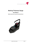
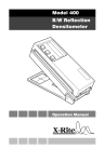
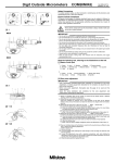
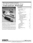
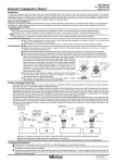
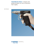
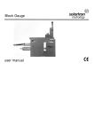
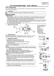
User’s Manual No.99MAG019B1 Series No.7•547 Bench Gage (Dial Type/Digital Type) 8. Attaching Bezel Clamp (Dial Type) Introduction Read this User’s Manual thoroughly before using the gage. After reading, retain it close at hand for future reference. Indicates a potentially hazardous situation which, if not avoided, may result in minor or moderate injury or property damage. 2. On Various Types of Notes I M P O R TAN T An important note provides information essential to the completion of a task. An important note is a type of precaution, which if neglected could result in a loss of data, decreased accuracy or instrument malfunction/failure. A note emphasizes or supplements important points of the main text. NOTE 3. Operating Environment I M P O R TAN T Use the gage in an environment with a temperature of 0 to 40㷄 and a relative humidity of 30 to 70%. Avoid sudden changes in temperature. Condensation may negatively affect the performance of the gage. Use the gage in a place with minimal exposure to dust, oil and oil mist. Use the gage in a place out of direct sunlight. 4. Name of each part Indicator Lifting lever Hex screw Bezel Limit hand Bezel clamp Short hand Long hand Contact point Anvil Measuring table Spindle Base Support plate *The appearance of a gage varies with the model. 5. Specifications Code No. 7060 547-064 547-066S Measuring Range (Individual Indicator) 0 to 23 mm (0 to 10 mm) 0 to 25 mm (0 to 12 mm) 0 to 1” / 0 to 25 mm (0 to .5” / 0 to 12 mm) Accuracy Indicator Graduation Contact point I 6.3 flat ±15 ȝm 2046SB 0.01 mm ±20 ȝm 543-400BS (ID-C1012XBS) 0.01 mm ±.001” 543-402BS (ID-C1012EXBS) .0005” /0.01 mm Diameter Measuring Table Flatness Stroke Anvil Stroke I 20 5 ȝm 10 mm 13 mm I 6.3 flat contact point I 20 5 ȝm 10 mm 13 mm .25”DIA flat contact point I 20 5 ȝm 10 mm .5” contact point 6. Notes on Use I M P O R TAN T Do not suddenly activate the spindle or apply an excessive horizontal load. Be sure to check the accuracy of gage if it has been dropped or otherwise subjected to shock. Ensure that the spindle and hands operate smoothly. Also check that the digital display is working properly. Ensure that the contact point and screw are not loose. Regularly check and adjust the reference point when using the gage in a place subject to temperature variation. A resin spacer is in the sliding part of a lifting lever. This spacer supports the movement of the lifting lever so that it should not be removed. 7. Attaching and Removing Limit Hand (Dial Type) Separate the limit hand before attaching it. ޛAttachmentޜ Limit hand ޛRemovalޜ dovetail groove (2)䋺Fix with clamp screw. Clamp bracket 㩿㪈㪀㩷 N o t e Take note that the clamp may loosen or fall off under vibration. 9. Attaching and Removing the Lifting Lever 䇴Attachment䇵 (1)䋺Lift the spindle and fit the forked end of the lifting lever to the spindle stop under the spacer. (2)䋺Fit the lifting lever into the dovetail groove and fix in position by pushing down in the direction of the arrow. 㩿㪉㪀㩷 㩿㪈㪀㩷 䇴Removal䇵 (1)'䋺Push the finger rest up in the direction of the arrow and remove the lifting lever. 㩿㪈㪀㩾㩷 Dovetail groove 10. Instructions for Use 1) Wipe the contact point and the measuring surface of the anvil to remove any dust. 2) Adjust the height of the measuring table and fix it using hex screws. 3) Adjust the position of the anvil and fix it using hex screws. 4) Adjust the support plate, place the gage on an angle and fix it using hex screws. Make sure that the gage is on a suitable angle so that the indicated value can be easily read. 5) Set the reference point. Set the anvil measuring surface or master gage (gauge block, etc.) as the reference surface. Use the lifting lever and release to move the contact point up and down several times. Check that the graduation value when the contact point touches the reference surface is stable. 䊶 Dial type gage ··········· Adjust the long hand so that it points to the zero graduation mark by rotating the bezel. 䊶 Digital type gage ········· Press the ZERO/ABS button. (This is useful when the master gage is set as the reference surface because the measurement value can be automatically read by using the PRESET function. See the Digimatic Indicator User’s Manual for details of the PRESET function.) Use the lifting lever and release again to check that the reference point has not shifted. 6) Measure the workpiece. Use the lifting lever and release to slowly bring the contact point into contact with the workpiece. Repeat this several times and read the value after checking that the graduation value is stable. NOTE If a master gage is used to set zero, the measured dimension will be the sum of the indicated value and the master gage dimension. (It can not be applied when using the PRESET function.) 䇶Reference䇷Tolerance judgment It is possible to judge whether the workpiece dimensions are within the tolerance range by comparing the workpiece dimensions using the master gage dimensions as a reference. 䊶 Dial type gage············· Set the tolerance by attaching a limit hand to the positions of the upper and lower limit values. Judge whether the workpiece dimensions are within the tolerance range by determining whether the long hand points within the allowable range indicated by the limit hands when the workpiece is measured. Be aware of the value indicated by the short hand to avoid misreading one rotation of the long hand. 䊶 Digital type gage ········· Set the tolerance by using the tolerance setting function. Judge whether the workpiece dimensions are within the tolerance range via the symbol that is displayed when the workpiece is measured. (See the Digimatic Indicator User’s Manual for details of the tolerance setting function.) 11. Maintenance and Repairs I M P O R TAN T 䊶 When carrying the gage, be sure to hold the frame so that you do not drop the unit. 䊶 Remove dirt or dust from the sliding surface of the spindle using a dry cloth or a cloth on which a small amount of alcohol has been applied. 䊶 Remove dirt or dust on the bezel or digital display surface using a soft dry cloth or a cloth on which a neutral detergent has been applied. Do not use substances other than a neutral detergent to clean the bezel or digital display surface. 㩿㪉㪀㩷 䊶 Apply an anti-rust oil containing a small amount of anti-rusting agent to the measuring table before storing the gage. 㩿㪈㪀㩷 Take care not to injure yourself when separating the limit 㪚㪸㫌㫋㫀㫆㫅㩷 hand or handling the separated parts. Clamp screw Clamping plate (1)䋺Insert clamp bracket in the 1. Safety Precautions Caution 㩿㪉㪀㩷 䇴Attachment䇵 䊶 The performance deterioration of this gage differs greatly depending on the usage conditions. Customers are therefore advised to Bezel (1)䋺Attach the limit hand to the bezel. (2)䋺Push the limit hand all the way until it clicks. establish in-house standards that take into consideration the actual usage frequency, environment, and method, and perform 㩿㪈㪀㩾㩷 (1)' 䋺 To remove the limit hand push it up in the direction of the arrow. regular maintenance checks on the gage based on these standards. 䊶 Mitutoyo does not guarantee the performance of this gage if repair or disassembly has been performed by other than Mitutoyo.