1
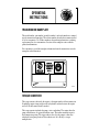
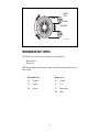
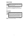
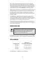
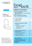
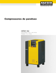
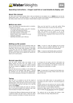
Operator’s Manual Allison Cycling Transmissions CRT 3000, CRT 5000, CRT 7000 OM1355EN MT4108EN OM1355EN Operator’s Manual Allison Cycling Transmissions CRT 3321 CRT 3331 CRT 3531 CRT 3630 CRT 5530 CRT 5630 CRT 5631 CRT 5633 CRT 5643 CRT 7033 DECEMBER 2002 Allison Transmission, Inc. P.O. Box 894 Indianapolis, Indiana 46206-0894 www.allisontransmission.com Printed in U.S.A. i Copyright © 2007 Allison Transmission, Inc. WARNINGS, CAUTIONS, AND NOTES IT IS YOUR RESPONSIBILITY to be completely familiar with the warnings and cautions described in this handbook. It is, however, important to understand that these warnings and cautions are not exhaustive. Allison Transmission could not possibly know, evaluate, and advise the service trade of all conceivable ways in which service might be done or of the possible hazardous consequences of each way. Consequently, Allison Transmission has not undertaken any such broad evaluation. Accordingly, ANYONE WHO USES A SERVICE PROCEDURE OR TOOL WHICH IS NOT RECOMMENDED BY ALLISON TRANSMISSION MUST first be thoroughly satisfied that neither personal safety nor equipment safety will be jeopardized by the service methods selected. Proper service and repair is important to the safe, reliable operation of the equipment. The service procedures recommended by Allison Transmission and described in this handbook are effective methods for performing service operations. Some of these service operations require the use of tools specially designed for the purpose. The special tools should be used when and as recommended. Three types of headings are used in this manual to attract your attention. These warnings and cautions advise of specific methods or actions that can result in personal injury, damage to the equipment, or cause the equipment to become unsafe. WARNING: A warning is used when an operating procedure, practice, etc., if not correctly followed, could result in personal injury or loss of life. CAUTION: A caution is used when an operating procedure, practice, etc., if not strictly observed, could result in damage to or destruction of equipment. NOTE: A note is used when an operating procedure, practice, etc., is essential to highlight. TRADEMARK INFORMATION DEXRON® is a registered trademark of General Motors Corporation. Biobor® JF is the registered trademark for a biological inhibitor manufactured by U.S. Borax and Chemical Corporation. TranSynd™ is a trademark of Castrol Limited. ii TABLE OF CONTENTS Page INTRODUCTION CRT 3000 Series Transmissions . . . . . . . . . . . . . . . . . . . . . . . . . . . . . . . . . . . .1 Inside the CRT 3000 Series . . . . . . . . . . . . . . . . . . . . . . . . . . . . . . . . . . . . . . . .3 CRT 5530–5630 Series Transmissions . . . . . . . . . . . . . . . . . . . . . . . . . . . . . . .4 Inside the CRT 5633 Series . . . . . . . . . . . . . . . . . . . . . . . . . . . . . . . . . . . . . . . .6 CRT 5643 Series Transmissions . . . . . . . . . . . . . . . . . . . . . . . . . . . . . . . . . . . .7 Inside the CRT 5643 Series . . . . . . . . . . . . . . . . . . . . . . . . . . . . . . . . . . . . . . . .9 CRT 7000 Series Transmissions . . . . . . . . . . . . . . . . . . . . . . . . . . . . . . . . . . .10 Inside the CRT 7000 Series . . . . . . . . . . . . . . . . . . . . . . . . . . . . . . . . . . . . . . .12 OPERATING INSTRUCTIONS Transmission Nameplate . . . . . . . . . . . . . . . . . . . . . . . . . . . . . . . . . . . . . . . . .13 Torque Converter. . . . . . . . . . . . . . . . . . . . . . . . . . . . . . . . . . . . . . . . . . . . . . .13 Transmission Shift Levers . . . . . . . . . . . . . . . . . . . . . . . . . . . . . . . . . . . . . . . .14 Starting Engine . . . . . . . . . . . . . . . . . . . . . . . . . . . . . . . . . . . . . . . . . . . . . . . .15 Operating In Cold Weather . . . . . . . . . . . . . . . . . . . . . . . . . . . . . . . . . . . . . . .15 Pressures, Temperatures . . . . . . . . . . . . . . . . . . . . . . . . . . . . . . . . . . . . . . . . .15 Speed Limitations When Shifting . . . . . . . . . . . . . . . . . . . . . . . . . . . . . . . . . .16 Changing Direction of Travel . . . . . . . . . . . . . . . . . . . . . . . . . . . . . . . . . . . . .16 Inching Control . . . . . . . . . . . . . . . . . . . . . . . . . . . . . . . . . . . . . . . . . . . . . . . .17 Clutch Cutoff Control . . . . . . . . . . . . . . . . . . . . . . . . . . . . . . . . . . . . . . . . . . .17 Power Takeoff Operation . . . . . . . . . . . . . . . . . . . . . . . . . . . . . . . . . . . . . . . .17 Towing or Pushing. . . . . . . . . . . . . . . . . . . . . . . . . . . . . . . . . . . . . . . . . . . . . .18 Parking Brake . . . . . . . . . . . . . . . . . . . . . . . . . . . . . . . . . . . . . . . . . . . . . . . . .18 CARE AND MAINTENANCE Periodic Inspections. . . . . . . . . . . . . . . . . . . . . . . . . . . . . . . . . . . . . . . . . . . . .19 Daily Prestart Checks . . . . . . . . . . . . . . . . . . . . . . . . . . . . . . . . . . . . . . . . . . .19 Importance of Proper Fluid Level . . . . . . . . . . . . . . . . . . . . . . . . . . . . . . . . . .20 Cold Fluid Level Check (With Add and Full Check Ports). . . . . . . . . . . . . . .20 Cold Fluid Level Check (One Check Port) . . . . . . . . . . . . . . . . . . . . . . . . . . .21 Hot Fluid Level Check (With Add and Full Check Ports) . . . . . . . . . . . . . . .21 Hot Fluid Level Check (One Check Port) . . . . . . . . . . . . . . . . . . . . . . . . . . . .22 Fluid Recommendations . . . . . . . . . . . . . . . . . . . . . . . . . . . . . . . . . . . . . . . . .22 Fluid and Filter Change . . . . . . . . . . . . . . . . . . . . . . . . . . . . . . . . . . . . . . . . . .22 Keeping Fluid Clean . . . . . . . . . . . . . . . . . . . . . . . . . . . . . . . . . . . . . . . . . . . .23 iii Refill Capacities. . . . . . . . . . . . . . . . . . . . . . . . . . . . . . . . . . . . . . . . . . . . . . . .23 Care of Breather. . . . . . . . . . . . . . . . . . . . . . . . . . . . . . . . . . . . . . . . . . . . . . . .24 Control Linkage Adjustment . . . . . . . . . . . . . . . . . . . . . . . . . . . . . . . . . . . . . .24 Parking Brake Adjustment. . . . . . . . . . . . . . . . . . . . . . . . . . . . . . . . . . . . . . . .24 Prevent Major Problems . . . . . . . . . . . . . . . . . . . . . . . . . . . . . . . . . . . . . . . . .24 Troubleshooting. . . . . . . . . . . . . . . . . . . . . . . . . . . . . . . . . . . . . . . . . . . . . . . .25 Preservation and Storage . . . . . . . . . . . . . . . . . . . . . . . . . . . . . . . . . . . . . . . . .27 CUSTOMER SERVICE Owner Assistance . . . . . . . . . . . . . . . . . . . . . . . . . . . . . . . . . . . . . . . . . . . . . .29 Service Literature. . . . . . . . . . . . . . . . . . . . . . . . . . . . . . . . . . . . . . . . . . . . . . .31 Allison Transmission Distributors. . . . . . . . . . . . . . . . . . . . . . . . . . . . . . . . . .32 Allison Transmission Regional Offices. . . . . . . . . . . . . . . . . . . . . . . . . . . . . .35 Technical Assistance Center . . . . . . . . . . . . . . . . . . . . . . . . . . . . . . . . . . . . . .36 iv EADING ED GE E L TH INTRODUCTION OF TEC H N OLOGY V01963 CRT 3000 SERIES TRANSMISSIONS CRT 3331-3 Matched to engines in the 70–185 horsepower (52–139 kW) class, reversing transmissions provide every desirable feature for cycling operations. Rugged and compact, these units contain all the transmission elements in a single package. This package contains a torque converter, a forward and reverse planetary gear set, and either one or two range planetary gear sets, depending on the model. Hydraulically actuated clutches provide smooth, fast, full-power shifting in each range and a smooth transition between forward and reverse operation. 1 CRT 3531-1 Optional features include: • Remote mount or direct engine mount • Flex disk or grease ring drive • Clutch cutoff control valve • Inching control valve • Steer pump drive • Speedometer drive • Governor drive • Remote transmission mounted oil filter • Remote or direct mount oil cooler • Parking brake • Front output disconnect • Heavy duty front output shaft • Choice of popular flanges • Remote mount sump • Power takeoff • Choice of torque converter ratios • Straight-through or dropbox models • Remote torsional dampening coupling. 2 INSIDE THE CRT 3000 SERIES Inside the CRT 3000 Series The torque converter includes a pump, stator, and turbine. It functions as a torque multiplier or as a fluid coupling, depending upon load and operating conditions. The planetary gear train, in all models except CRT 3321, consists of a forward planetary gear set, a reverse planetary gear set, and two range planetary gear sets. These planetaries are combined with five clutches to provide three forward ranges and three reverse ranges. The CRT 3321 has a forward planetary gear set, a reverse planetary gear set, and one range planetary gear set. These are combined with four clutches to provide two forward ranges and two reverse ranges. The operator controls the application of the clutches by moving the directional control lever and range control lever. Some models of the CRT 3000 Series are equipped with a transfer case (dropbox) which places the transmission output on a lower level than the input. This permits a forward output as well as a rear output. A front output disconnect is available. A single integral hydraulic system serves the torque converter and range gearing. Oil for all hydraulic operations is supplied from the same integral sump and is returned to it. 3 CRT 5530–5630 SERIES TRANSMISSIONS These transmissions set the standard for reliability and high work output. Allison Transmission CRTs are reversing transmissions that provide: • • • • • • Full-power crowd and bucket loading ability Continuous, sensitive feel of the road Hydraulic clutch cutoff Smooth handling of off-balance loads Positive positioning for load spotting Faster reversing. Matched with engines in the 175–430 horsepower (130–320 kW) class these rugged and complete units contain all transmission components in one compact package. This package consists of a torque converter for a powerful starting torque, a forward and reverse planetary gear set, and two range planetary gear sets. Hydraulically actuated clutches provide smooth, fast, full-power shifting in each of the three 4 forward ranges and three reverse ranges, and smooth transition between forward and reverse operation. Optional features include: • • • • • • • • • Remote mount or direct engine mount Parking brake Remote or transmission mounted oil filter Speedometer drive Choice of popular flanges Power takeoff Implement pump drive Clutch cutoff valve (air or hydraulic) Choice of torque converter ratio. 5 INSIDE THE CRT 5633 SERIES The torque converter includes a pump, stator, and turbine. It functions as a torque multiplier or fluid coupling, depending upon load and operating conditions. The planetary gear train consists of four constant mesh planetary gear sets. The front set is forward set, followed by reverse, high-range, and intermediate-range set. These planetaries are combined with five clutches to provide three forward ranges and three reverse ranges. The operator controls the application of the clutches by moving the directional control lever and range control lever. The transmission output is a transfer case (dropbox) which places the output on a lower level than the input. This permits both a front and rear output. A parking brake mounted on the rear output is available as an option. A single integral hydraulic system serves the torque converter and range gearing. Oil for all hydraulic operations is supplied from the same integral sump and is returned to it. 6 CRT 5643 SERIES TRANSMISSIONS These transmissions set the standard for reliability and high work output. Allison Transmission CRTs are reversing transmissions that provide: • • • • • • Full-power crowd and bucket loading ability Continuous, sensitive feel of the road Hydraulic clutch cutoff Smooth handling of off-balance loads Positive positioning for load spotting Faster reversing. Matched with engines in the 175–430 horsepower (130–320 kW) class these rugged and complete units contain all transmission components in one compact package. This package consists of a torque converter for powerful starting torque, a forward 7 and reverse planetary gear set, and two range planetary gear sets. Hydraulically actuated clutches provide smooth, fast, full-power shifting in each of the three forward ranges and three reverse ranges, and smooth transition between forward and reverse operation. Optional features include: • • • • • • • • Remote or transmission mounted oil filter Speedometer drive Choice of popular flanges Power takeoff Implement pump drive Clutch cutoff valve (air or hydraulic) Parking brake Choice of torque converter ratio. 8 INSIDE THE CRT 5643 SERIES The torque converter includes a pump, stator, and turbine. It functions as a torque multiplier or as a fluid coupling, depending upon load and operating conditions. The planetary gear train consists of four constant mesh planetary gear sets. The front set is the forward set, followed by reverse, high-range, and intermediate-range sets. These planetaries are combined with five clutches to provide three forward ranges and three reverse ranges. The operator controls the application of the clutches by moving the directional control lever and range control lever. The transmission output is a transfer case (dropbox) which places the output on a lower level than the input. This permits both a forward and rear output A single integral hydraulic system serves the torque converter and range gearing. Oil for all hydraulic operations is supplied from the same integral sump and is returned to it. 9 CRT 7000 SERIES TRANSMISSIONS CRT 7033 Applications for these transmissions are as varied as the number of cycling vehicles and vocations. They are designed to meet extreme duty and long life requirements in applications such as: • • • • • • • • Wheel loaders Forklift trucks Compactors Motor graders Specialized mining equipment Rubber-tire tractors Log loaders Similar cycling applications. Smooth shifting at full power while changing direction of travel in low-range is the direct benefit of the soft shift feature built into these reversing transmissions. 10 Other features are: • • • • • • Full-power crowd and bucket loading ability Sensitive feel of the load Hydraulic clutch cutoff Smooth handling of off-balance loads Positive positioning for load spotting Fast reversing. Matched with engines in the 320–440 horsepower (239–328 kW) class, these rugged and complete units contain all transmission components in one package. This package consists of a three-element, single stage torque converter for a powerful starting torque, a forward and reverse planetary gear set, and two range planetary gear set. Hydraulically actuated clutches provide smooth, fast, full-power shifting in each of the three forward ranges and three reverse ranges, and smooth transition between forward and reverse operation. Optional features include: • • • • • • • • • Remote mount or direct engine mount Parking brake Remote or transmission mounted oil filter Speedometer drive Choice of popular flanges Power takeoff Implement pump drive Clutch cutoff valve (air or hydraulic) Choice of torque converter ratio. 11 INSIDE THE CRT 7000 SERIES The torque converter includes a pump, stator, and turbine. It functions as a torque multiplier or as a fluid coupling, depending upon load and operating conditions. The planetary gear train consists of four constant mesh planetary gear sets. The front set is the forward set, followed by reverse, high-range, and intermediate-range sets. These planetaries are combined with five clutches to provide three forward ranges and three reverse ranges. The operator controls the application of the clutches by moving the directional control lever and range control lever. All models of the CRT 7000 Series are equipped with a transfer case (dropbox) which places the transmission output on a lower level than the input. This permits a front output as well as a rear output. A single integral hydraulic system serves the torque converter and range gearing. Oil for all hydraulic operations is supplied from the same integral sump and is returned to it 12 EADING ED GE E L TH OPERATING INSTRUCTIONS OF TEC H N OLOGY V01963 TRANSMISSION NAMEPLATE The model number, part number (assembly number), and serial number are stamped into the transmission nameplate. These three numbers describe the transmission and all of its components. Use all three numbers when seeking information or ordering replacement parts for a transmission. Location of the nameplate varies with the particular transmission. For convenience, record the nameplate information from the transmission onto the nameplate in the illustration. D AGR ICULTURA L OF AM E ERI CA UNITE DA ILE AEROSPAC WORKERS OB UAW 933 ENT OM IM EM UT SERIAL NO. AN PL DIVISION OF GENERAL MOTORS CORPORATION INDIANAPOLIS INDIANA PART NO. MODEL NO. V02779 TORQUE CONVERTER The torque converter, driven by the engine, is the input member of the transmission. It multiplies engine torque and provides an hydraulic cushion between the engine and load. No disconnect clutch is needed. The torque converter includes the pump, stator, and turbine. The engine drives the pump, which throws oil against the turbine vanes. The turbine transmits torque to the transmission gearing. The stator redirects the oil to the pump in a direction which will assist pump rotation. This redirection of oil is the key to torque multiplication. 13 VORTEX FLOW TURBINE CULAR FLOW CIR PUMP STATOR V07942.00.00 TRANSMISSION SHIFT LEVERS Two shift levers are used to control operation of the transmission: • Direction lever • Range lever. The following shift patterns show the sequence of the shift levers for directional and range control. Directional Lever Range Lever F Forward N Neutral N Neutral L Low R Reverse I Intermediate H High 14 STARTING ENGINE Place the range selector lever in the neutral position before starting the engine. If the transmission is equipped with a neutral start switch, the switch will prevent the engine from starting unless the range selector lever is in neutral. If the starter will not operate in neutral or will operate in any range other than neutral, report this to maintenance personnel immediately. OPERATING IN COLD WEATHER Type C4 fluids are recommended for use in off-highway applications. When ambient temperature is below the minimum fluid temperature and the transmission is cold, preheat is required. If auxiliary heating equipment is available, preheat the fluid to the minimum temperature. If auxiliary heating equipment is not available, run the engine for at least 20 minutes with the transmission in NEUTRAL before operating in a forward or reverse range. Failure to observe the minimum fluid temperature can result in erratic shift patterns or reduced transmission life. Select the fluid viscosity best suited to the ambient temperature conditions in the operating area listed in Table 1, or refer to the most recent version of SIL 13-TR-90. Table 1. Transmission Fluid Recommendations Minimum Operating Temperature SAE Viscosity Grade* or Fluid Type Degrees (C) Degrees (F) 0W-20 (Arctic Oil) or TranSynd –30 –22 DEXRON-III –25 –13 10W –20 –4 15W-40 –15 5 SAE 30 0 32 SAE 40 10 50 * SAE “W” designation means winter weight based on cold temperature properties. PRESSURES, TEMPERATURES Check transmissions pressure and temperature gauges frequently to determine if readings are within normal operating range. Normal operating range is 180–250ºF (82–121ºC). Fluid temperature should not exceed 275ºF (135ºC). If fluid temperature reaches this limit, stop the vehicle, shift into Neutral, and increase engine speed to 1200–1500 rpm. Fluid temperature should return to normal operating range before continuing operation of the vehicle. 15 If high fluid temperature persists, stop the engine and have the overheating condition investigated by maintenance personnel. CAUTION: The engine should never be operated for more than 30 seconds at full throttle with the transmission in gear and the vehicle not moving. Prolonged operation of this type will cause excessively high transmission fluid temperature which could be detrimental to the transmission. The transmission fluid pressure gauge indicates clutch apply pressure. The needle will very with transmission shifting and speeds, but should return to normal at normal engine operating speeds. Shut off the engine if the pressure remains abnormal. Have maintenance personnel investigate abnormal fluid pressure. SPEED LIMITATIONS WHEN SHIFTING The transmission may be upshifted or downshifted at full throttle. However, a downshift MUST NOT be made if the vehicle speed exceeds maximum speed normally attainable in the next lower range. Downshifting at excessive speed will overspeed the engine. There is no speed limitation on upshifting. CHANGING DIRECTION OF TRAVEL CRT 3000 Series To shift from forward to reverse or reverse to forward, close the throttle and brake to a slow (creeping) speed. Then move the directional lever to the opposite direction. Reopen the throttle when the vehicle begins to move in the opposite direction. CRT 5000-7000 Series These transmissions have an unique feature which allows them to be shifted from forward to reverse or reverse to forward at full throttle and full speed in low range. To shift from forward to reverse or reverse to forward when in low range, just move the directional lever in the opposite direction. Clutch engagement will be automatically trimmed to provide a smooth transition to the opposite direction. To shift from forward to reverse or reverse to forward while operating in intermediate- or high-range, close the throttle and brake to a slow (creeping) speed. Then move the directional lever to the opposite direction. Reopen the throttle when the vehicle begins to move in the opposite direction. 16 INCHING CONTROL Some transmissions are equipped with an inching control feature. This is a valve which is controlled by the operator separately from the range selector and directional selector. This valve is manipulated by the operator to accurately control the application of main pressure to the forward or reverse clutch. Thus, the operator has a feel of the load pickup and precise “inching” of the load. CLUTCH CUTOFF CONTROL Some transmissions are equipped with a clutch cutoff or “declutch” device. This control eliminates the need to shift to NEUTRAL when full engine power is needed to drive accessory equipment, such as a bucket. The device is actuated when the operator fully applies the service brakes. After the brake pedal passes through the first portion of the stroke (some linkages have a detent), the clutches are completely released. When the brake pedal is released, the clutches are reapplied. Some installations are equipped with an ON/OFF switch which allows the operator to lock out the clutch cutoff: • When “roading” the vehicle over long distances • When inching the vehicle forward or backward in tight quarters • Whenever the clutch cutoff is not wanted with each brake application. POWER TAKEOFF OPERATION All transmissions have provisions for a power takeoff (PTO) at the front of the transmission. The PTO is engine driven and rotates whenever the engine is running. In most applications, the PTO is continuous and drives an hydraulic pump which supplies hydraulic pressure for various accessories. In addition to the engine driven PTO, the CRT 5600 Series may also have a PTO driven by the transmission output. This allows the operator to operate the PTO in either low-, intermediate-, or high-range as well as forward or reverse. A mechanical disconnect allows the operator to engage or disengage the PTO. The transmission output PTO will not operate when: • • • • The rear disconnect is in the OFF position The range selector lever is in NEUTRAL The directional lever is in NEUTRAL The clutch cutoff is in the ON position and the service brakes are applied. 17 TOWING OR PUSHING CAUTION: Failure to lift the driving wheels off the road, disconnect the driveline, or remove the axle shafts before pushing or towing can cause serious transmission damage. Before towing the vehicle, be sure to lift the drive wheels off the ground or disconnect the driveline to avoid damage to the transmission. Because of the design of the hydraulic system, the engine CANNOT be started by towing or pushing the vehicle. PARKING BRAKE WARNING: Take the following precautions so that unexpected and possible sudden vehicle movement is avoided. Whenever it becomes necessary to leave the vehicle, even momentarily, while the engine is in operation, place the transmission shift selector in N (Neutral) (or for special pumping operations, disconnect drive to the wheels), set the parking brake and/or emergency brakes, and chock the wheels. Since there is no “park” position in the shift pattern, the parking brake MUST BE APPLIED to hold the vehicle when it is unattended. 18 EADING ED GE E L TH CARE AND MAINTENANCE OF TEC H N OLOGY V01963 PERIODIC INSPECTIONS WARNING: If you leave the vehicle and the engine is running, the vehicle can move suddenly and you or others could be injured. If you must leave the engine running, do not leave the vehicle until you: • Put the transmission in N (Neutral) • Apply the parking brake and emergency brakes and make sure they are properly engaged • Chock the wheels and take any other steps necessary to keep the vehicle from moving. Scheduled maintenance is necessary on an Allison Powershift transmission. Careful attention should be given to all control linkage and fluid level. For easier inspection, keep the transmission clean. Make periodic inspections for: • Loose bolts • Leaking fluid line • Wet split lines. DAILY PRESTART CHECKS Control Linkages Check the transmission shift control linkage and directional linkage to be sure the linkages are free and selector levers are properly positioned. The shift lever should position freely in all ranges. Inspect the linkages for: • • • • • • Binding Wear Cracks Breaks Defective cotter pins An accumulation of grease or dirt. 19 Fluid Level Checks CAUTION: DO NOT start the engine until the presence of sufficient transmission fluid has been confirmed. • Before starting the engine, perform a cold fluid level check. This is to be sure that the transmission contains a sufficient quantity of fluid to lubricate and operate the transmission until it is warmed up. • Perform a hot fluid level check when the transmission reaches normal operating temperature. • Some transmissions may be equipped with either a petcock or a plug for checking the fluid level. Some models have only one petcock or plug while other models have two. On transmissions with two petcocks or plugs, the lower one is the ADD level and the upper one is the FULL level. IMPORTANCE OF PROPER FLUID LEVEL CAUTION: Low or high fluid level can cause overheating and irregular shift patterns. These conditions can damage the transmission if not corrected. Maintaining the proper fluid level is very important. Transmission fluid cools, lubricates, and transmits power. If the fluid level is too low, the torque converter and clutches will not get a proper fluid supply. If the fluid level is too high, the fluid will become aerated and cause overheating. COLD FLUID LEVEL CHECK (WITH ADD AND FULL CHECK PORTS) Before starting the engine do all of the following: • Open the ADD (lower port) petcock or remove the plug. If fluid flows from the ADD port, the transmission has sufficient fluid to permit starting the engine. If the fluid level is below the ADD port, add fluid until it flows from the port. Close the petcock or replace the plug. • Open the FULL (upper port) petcock or remove the plug. If fluid flows from the FULL port, allow the excess to drain. Then close the petcock or replace the plug. When the transmission reaches normal operating temperature, perform a hot fluid level check. 20 COLD FLUID LEVEL CHECK (ONE CHECK PORT) Before starting the engine, open the check port petcock or remove the plug. Do one of the following: • If the fluid level is below the check port, add fluid until it flows from the port. • If fluid flows from the port, allow the excess to drain. Close the petcock or replace the plug. When the transmission reaches normal operating temperature, perform a hot fluid level check. HOT FLUID LEVEL CHECK (WITH ADD AND FULL CHECK PORTS) CAUTION: The transmission must not be operated for extended periods of time until a Hot Check has verified proper fluid level. Transmission damage can result from extended operation at improper fluid level conditions. CAUTION: An accurate fluid level check cannot be made unless the engine is idling (500–800 rpm) in N (Neutral), the transmission fluid is at the proper temperature, and the vehicle is on a level surface. To perform a hot fluid level check, the transmission MUST BE at normal operating temperature, the transmission MUST BE in NEUTRAL, and the engine MUST BE running at 500–800 rpm. Do all of the following: • Open the FULL (upper port) petcock or remove the plug. If fluid flows from the FULL port, observe the type of flow. If it is aerated or flows freely in a full stream, allow the fluid to drain down to the FULL port. Then close the petcock or replace the plug. • If fluid does not flow from the FULL port, open the ADD (lower port) petcock or remove the plug. If fluid flows from the ADD port, the level is satisfactory. If no fluid flows from the ADD port, add fluid to bring the level to the FULL port opening. Close all petcocks or replace all plugs. 21 HOT FLUID LEVEL CHECK (ONE CHECK PORT) To perform a hot fluid level check, the transmission MUST BE at normal operating temperature, the transmission MUST BE in NEUTRAL, and the engine MUST BE running at 500–800 rpm. Do all of the following: • Open the petcock or remove the plug from the fluid level check port. If the fluid level is below the check port, add fluid until it flows from the port. • If fluid flows from the port, observe the type of flow. If it is aerated or flows freely in a full stream, allow the fluid to drain down to the check port. • Close the petcock or replace the plug. FLUID RECOMMENDATIONS CAUTION: Disregarding minimum fluid temperature limits can result in transmission malfunction or reduced transmission life. Hydraulic fluids used in the transmission have an important effect on transmission reliability. Type C4 fluids are recommended for use in off-highway applications. When ambient temperature is below the temperature listed for a specific viscosity and the transmission is cold, preheating is required before full operation of the transmission. Select the fluid viscosity listed in Table 1 best suited to the ambient temperature conditions in the operating area or refer to the most recent version of SIL 13-TR-90. FLUID AND FILTER CHANGE CAUTION: Do not use containers or fillers for transmission fluid that have been used for any antifreeze solution. Antifreeze and coolant solutions contain ethylene glycol which, if introduced into the transmission, can cause the clutch plates to fail. CAUTION: Transmission fluid and filter change frequency is determined by the severity of transmission service. More frequent changes may be necessary than recommended in the general guidelines when operating conditions create high levels of contamination or overheating. The fluid should be changed every 1200 hours of operation or sooner depending on operating conditions. Also, the fluid must be changed whenever there are traces of 22 dirt or evidence of high temperature indicated by discoloration or strong odor. Remove and clean the screen in the sump with mineral spirits at each fluid change. Metal particles in the fluid (except for the minute particles normally trapped in the oil filter) indicate damage has occurred in the transmission. When these particles are found in the filter, report the condition immediately to maintenance personnel. The filter elements should be replaced at each fluid change and at 600-hour intervals between fluid changes or more frequently if necessary to avoid filter bypass. The filter shells should be cleaned. New gaskets and sealrings must be used when replacing filter elements. After installation, check the filters for fluid leakage while the engine is running. At each fluid change, examine the fluid which is drained for evidence of dirt or water. A normal amount of condensation will emulsify in the fluid during operation of the transmission. However, if there is evidence of water or engine coolant in the fluid, immediately report the condition to maintenance personnel. The fluid and filter change interval should be adjusted to meet the requirements of local conditions. Environmental conditions, severity of duty cycle, etc. may dictate a longer or shorter change interval. KEEPING FLUID CLEAN CAUTION: Do not use containers or fillers for transmission fluid that have been used for any antifreeze solution. Antifreeze and coolant solutions contain ethylene glycol which, if introduced into the transmission, can cause the clutch plates to fail. It is absolutely necessary that the fluid put into the transmission is clean. Fluid must be handled in clean containers to prevent foreign material from entering the system. REFILL CAPACITIES Transmission Series Refill Capacity (less external circuits and filters) CRT 3000 5.5 US gal (20.8 liters) CRT 5000 11.25 US gal (42.6 liters) CRT 7000 11.25 US gal (42.6 liters) After refilling, make a cold fluid check and a hot fluid check. 23 CARE OF BREATHER Keep the breather clean at all times. Check and clean the breather regularly and as frequently as necessary, depending on the operating conditions. A badly corroded or plugged breather restricts proper breathing and causes a buildup of condensation and subsequent fluid deterioration. CONTROL LINKAGE ADJUSTMENT Control linkages must be adjusted so that the operator’s control is positioned to exactly match the detent position of the selector valve on the transmission. Adjust the linkage so that it can be freely connected without moving either the valve or the operator’s control. Then operate the range selector lever, the directional selector lever, and the output disconnect (if applicable) through each position. Make adjustments, as necessary, to be sure that each selector lever seats in each position of the operator’s control. Then inspect the control linkage for binding, wear, or breaks. PARKING BRAKE ADJUSTMENT The internal, expanding shoe-type parking brake is mounted on the rear of the transmission housing at the output. Adjust the parking brake as follows: • Using two 0.010 inch (0.25 mm) feeler gauges, simultaneously insert each one between the adjusting ends of each shoe and the drum. Adjust the brake shoes by inserting a screwdriver or brake adjusting tool into a hole at the end of the brake shoes. The star wheel should be rotated until the two feeler gauges are held snugly between the adjusting ends of the shoes and the brake drum. • When properly adjusted, brake linkage should be able to be freely connected to or disconnected from the apply lever on the brake without actually moving the brake. Fully release the hand lever before starting the adjustment. Remove all slack from the linkage but be sure the linkage can be freely removed when the adjustment has been completed. PREVENT MAJOR PROBLEMS Minor problems can be kept from becoming major problems if maintenance personnel are notified when these conditions occur: • • • • Overheating Shifting feels odd Transmission leaks fluid Unusual sounds 24 TROUBLESHOOTING Investigate unusual conditions immediately to protect the life of the transmission. The following chart lists the possible causes of and remedies for unusual transmission conditions. As indicated in the chart, the engine and transmission must be considered as single package. Cause Remedy A LOW CLUTCH-APPLY PRESSURE (transmission fluid pressure gauge) 1. Low fluid level 1. Add fluid to correct level 2. Clogged oil strainer 2. Clean strainer 3. Clogged oil filter 3. Replace filter element 4. Inching control linkage not fully retracted 4. Check, adjust linkage 5. Air leak at intake side of oil pump 5. Check pump mounting bolts 6. External fluid leakage 6. Tighten bolts or replace gaskets 7. Brake hydraulic (or air) pressure 7. Check brake residual pressure (brakes released); check brakes for full release 8. Internal failure 8. Overhaul transmission or rebuild subassembly B OVERHEATING 1. High fluid level 1. Restore proper fluid level 2. Clutch failed 2. Rebuild transmission 3. Vehicle overloaded 3. Reduce load 4. Low clutch-apply pressure 4. Refer to A 5. Engine water overheated 5. Correct engine overheat 6. Cooler fluid or water line kinked or clogged 6. Clean or replace line C AERATED (foaming) FLUID 1. Incorrect type of fluid used 1. Change fluid, use proper type 2. High fluid level 2. Restore proper fluid level 3. Low fluid level 3. Restore proper fluid level 4. Air entering suction side of oil pump 4. Check oil pump bolts and gaskets 5. Air entering at clutch cutoff valve (air actuated) 5. Check plug seal and sealring of valve 25 Cause Remedy D VEHICLE WILL NOT TRAVEL 1. Low clutch-apply pressure 1. Refer to A 2. Selector linkage broken or disconnected 2. Repair or correct linkage 3. Internal mechanical failure 3. Overhaul transmission E VEHICLE TRAVELS IN NEUTRAL WHEN ENGINE IS ACCELERATED 1. Selector linkage out of adjustment 1. Adjust linkage 2. Clutch won’t release 2. Overhaul transmission F VEHICLE LACKS POWER AND ACCELERATION AT LOW SPEED 1. Low clutch-apply pressure 1. Refer to A 2. Low converter-out pressure 2. Refer to A 3. Low engine power 3. Check engine: refer to engine service manual 4. Aerated fluid 4. Refer to C G CLUTCH CUTOFF VALVE INEFFECTIVE 1. Valve or plug sticking 1. Rebuild control valve body assembly 2. Brake-apply hydraulic pressure incorrect 2. Check pressure at control valve; limit 130–200 psi (897–1378 kPa) 3. Brake-apply air pressure not reaching air cylinder 3. Check at air cylinder: 35 lb (156 N) force required to stroke valve 4. Plunger sticking in air cylinder 4. Check operation of air cylinder 5. Air entering at valve (air actuated) 5. Check operation of air cylinder (seals) 26 PRESERVATION AND STORAGE Storage, New Transmission (before installation) New transmissions are tested with preservative fluid and drained before shipment. The residual fluid remaining in the transmission provides adequate protection to safely store the transmission for up to one year without further treatment (stored inside in conditions of normal climate and with all shipping plugs installed). Preservation Methods When the transmission is to be stored or remain inactive for an extended period (one or more years), specific preservation methods are recommended to prevent damage due to rust, corrosion, and organic growth in the fluid. The following preservation methods are presented for storage with or without transmission fluid: • Storage, One Year—Without Transmission Fluid 1. Drain the fluid 2. Spray two ounces (60 milliliters) VCl #10 through the filltube 3. Seal all openings and the breather with moisture-proof tape 4. Coat all exposed, unpainted surfaces with preservative grease, such as petrolatum 5. If additional storage time is required, repeat the preceding steps at yearly intervals • Storage, One Year—With Transmission Fluid (normally installed in equipment) 1. Drain the fluid and replace the oil filter elements NOTE: When calculating the amount of Biobor JF required, use the total volume of the system, not just the quantity required to fill the transmission. Include the external lines, filters, and cooler. 2. Fill the transmission to operating level with a mixture of one part VCl #10 (or equivalent) to 30 parts Type C4 transmission fluid. Add 1/4 teaspoon of Biobor JF (or equivalent) for each gallon (0.1 ml/liter) of fluid in system. 3. Run the engine for approximately five minutes at 1500 rpm with the transmission in NEUTRAL. Operate the equipment. Make sure the transmission is shifted through all ranges and lockup. 27 4. Continue running the engine at 1500 rpm with the transmission in NEUTRAL until normal operating temperature is reached. CAUTION: If the equipment does not have a converter-out temperature gauge, do not stall the converter. 5. Because normal operating temperature is less than 225°F (107°C), shift the transmission to the highest forward range and stall the converter. When the converter-out temperature reaches 225°F (107°C), stop the engine. Do not exceed 225°F (107°C). 6. As soon as the transmission is cool enough to touch, seal all openings and the breather with moisture-proof tape. 7. Coat all exposed, unpainted surfaces with preservative grease, such as petrolatum MIL-C-11796, Class 2. 8. If additional storage time is required, repeat Steps 1–7 at yearly intervals. It is not necessary to drain the transmission each year, just add the VCl #10 and Biobor JF (or equivalent). Restoring Transmission to Service 1. Remove all tape from openings and breather 2. Wash off all external grease with mineral spirits 3. If transmission is new, drain the residual preservative fluid. Fill the transmission to the proper level with type C4 transmission fluid. 4. If the transmission was prepared for storage without fluid, drain the residual fluid and replace the oil filter elements. Fill the transmission to the proper level with type C4 transmission fluid. 5. If the transmission was prepared for storage with fluid, it is not necessary to drain and refill the transmission with new transmission fluid. Check for proper fluid level. Add or drain the transmission fluid as required to obtain the proper level. Refer to the Cold Fluid Level Check and Hot Fluid Level Check procedures. 28 EADING ED GE E L TH CUSTOMER SERVICE OF TEC H N OLOGY V01963 OWNER ASSISTANCE The satisfaction and goodwill of the owners of an Allison transmissions are of primary concern to Allison Transmission Division (ATD), its distributors, and their dealers. As an owner of an Allison transmission, you have service locations through the world that are eager to meet your parts and service needs with: • • • • • Expert service by trained personnel Emergency service 24 hours a day in many areas Complete parts support Sales teams to help determine your power requirements Product information and liturature Normally, any situation that arises in connection with the sale, operation, or service of your transmission will be handled by the distributor or dealer in your area (check either the local yellow pages or www.allisontransmission.com website for the Allison Transmission service outlet nearest you). Refer to the Worldwide Sales and Service Directory (SA2229EN) for the current listing of Allison Transmission authorized distributors and service dealers. This directory is available from SGI, Inc. We recognize, however, that despite the best intentions of everyone concerned, misunderstandings may occur. To further assure complete satisfaction, we have developed the following three-step procedure to be followed in the event you have a problem that has not been handled satisfactorily. Step One—Discuss the problem with a member of management from the distributorship or dealership. Frequently, complaints are the result of a breakdown in communication and can quickly be resolved by a member of management. If you have already discussed the problem with the Sales or Service manager, contact the General Manager. All ATD dealers are associated with an ATD distributor. If the problem originates with a dealer, explain the matter to a management member of the distributorship with whom the dealer has his service agreement. The dealer will provide his ATD distributor’s name, address, and telephone number on request. 29 Step Two—When it appears the problem cannot be resolved readily at the distributorship level without additional assistance, contact the Allison Transmission Regional Office responsible for the local distributorship. You will be assisted by a member of the Regional Service Manager’s staff, depending on the nature of your problem. For prompt assistance, please have the following information available: • Name and location of authorized distributor or dealer • Type and make of equipment • Transmission model number, serial number, and assembly number (if applicable). This data is available on the nameplate. • Transmission delivery date and accumulated miles and or hours of operation • Nature of problem • Chronological summary of unit’s history. Step Three—If you contact a regional office and you are still not satisfied, present the entire matter to the home office by writing to the following address or calling the telephone number below: Manager, Warranty Administration–PF9 Allison Transmission P O Box 894 Indianapolis, In 46206-0894 1-800-524-2303 The inclusion of all pertinent information will assist the Home Office in expediting the matter. If an additional review by the Home Office of all the facts involved indicates that some further action can be taken, the Regional Office will be advised. When contacting the Regional or Home Office, please keep in mind that ultimately the problem will likely be resolved at the distributorship or dealership utilizing their facilities, equipment, and personnel. Therefore, it is suggested the above steps be followed in sequence when experiencing a problem. Your purchase of an Allison Transmission product is greatly appreciated, and it is our sincere desire to assure complete satisfaction. 30 SERVICE LITERATURE Additional service literature is available for the owner who takes pride in his equipment. These books provide fully illustrated instructions for the maintenance, service, overhaul, and parts support of your transmission. To be sure that you get maximum performance and service life from your unit, you may order publications from: SGI, Inc. Attn: Allison Literature Fulfillment Desk 8350 Allison Avenue Indianapolis, IN 46268 TOLL FREE: 888-666-5799 INTERNATIONAL: 317-471-4995 Transmission Series Service Manual Parts Catalog CRT 3321, 3331 SM1073EN PC1244EN CRT 3531 SM1104EN PC1244EN CRT 3630 SM1104EN PC1244EN CRT 5530 — SA1076EN CRT 5630, 5631 SA1083EN SA1076EN CRT 5633, 5643 SA1547EN SA1559EN CRT 7033 SA2010EN SA2011EN 31 ALLISON TRANSMISSION DISTRIBUTORS EASTERN REGION Atlantic Detroit Diesel-Allison, LLC 180 Route 17 South Lodi, NJ 07644 201-489-5800 Penn Detroit Diesel-Allison, Inc. 8330 State Road Philadelphia, PA 19136-2986 215-335-0500 Covington Detroit Diesel-Allison 8015 Piedmont Triad Parkway Greensboro, NC 27409 336-292-9240 Western Branch Diesel, Inc. 3504 Shipwright Street Portsmouth, VA 23703 757-484-6230 Johnson & Towers, Inc. 2021 Briggs Road Mount Laurel, NJ 08054 856-234-6990 Williams Detroit Diesel-Allison Southeast, Inc. 2849 Moreland Avenue, S.E. Atlanta, GA 30315-0037 404-366-1070 New England Detroit Diesel-Allison, Inc. 90 Bay State Road Wakefield, MA 01880-1095 781-246-1810 32 CENTRAL REGION Caribe Detroit Diesel-Allison Division of GT Corporation Ceramic Ind. Park, Campo Rico Ave., Block C Carolina, Puerto Rico 00982 787-750-5000 Inland Diesel, Inc. 13015 West Custer Avenue Butler, WI 53007-0916 262-781-7100 Central Detroit Diesel-Allison, Inc. 9200 Liberty Drive Liberty, MO 64068 816-781-8070 Interstate Detroit Diesel 2501 East 80th Street Minneapolis, MN 55425 612-854-5511 Clarke Detroit Diesel-Allison, Inc. 3133 East Kemper Road Cincinnati, OH 45241 513-771-2200 Inland Detroit Diesel-Allison, Inc. 210 Alexandra Way Carol Stream, IL 60195 630-871-1111 Florida Detroit Diesel-Allison, Inc. 5105 Bowden Road Jacksonville, FL 32216 904-737-7330 Williams Detroit Diesel-Allison Midwest, Inc. 1176 Industrial Parkway, North Brunswick, OH 44212-2342 330-225-7751 SOUTHWESTERN REGION Detroit Diesel-Allison De Mexico S.A. De C.V. Av. Ejercito Nacional #843 Colonia Granada, Mexico D.F. C.P. 11520 525-901-3057 United Engines, Inc. 5555 West Reno Avenue Oklahoma City, OK 73127 405-947-3321 Stewart & Stevenson Power, Inc. 5840 Dahlia Street Commerce City, CO 80022 303-287-7441 Stewart & Stevenson Services, Inc. 2707 North Loop West Houston, TX 77008 713-868-7700 33 WESTERN REGION Pacific Detroit Diesel-Allison Company 7215 South 228th Street Kent, WA 98032 253-854-0505 Valley Detroit Diesel-Allison, Inc. 425 South Hacienda Boulevard City of Industry, CA 91745-1123 626-333-1243 Sierra Detroit Diesel-Allison, Inc. 1755 Adams Avenue San Leandro, CA 94577-1001 510-635-8991 Williams Detroit Diesel-Allison Southwest, Inc. 2602 S. 19th Avenue Phoenix, AZ 85009 602-257-0561 Smith Detroit Diesel-Allison, Inc. 250 West 3900 South Salt Lake City, UT 84107 801-262-2631 CANADIAN REGION Detroit Diesel-Allison British Columbia Ltd. 9300 - 192nd Street Surrey, British Columbia V4N 3R8 604-888-1211 Midwest Detroit Diesel-Allison Ltd. 1460 Waverley Street Winnipeg, Manitoba R3T OP6 204-452-8244 Detroit Diesel-Allison Canada East (Div. of Integrated Power Systems Corp.) 2997 Rue Watt Ste. Foy, Quebec G1X 3W1 418-651-5371 Waterous Detroit Diesel-Allison (Div. of Integrated Power Systems Corp) 10025 - 51 Avenue Edmonton, Alberta T6E OA8 780-437-3550 Harper Detroit Diesel Ltd. 10 Diesel Drive Toronto, Ontario M8W 2T8 416-259-3281 34 ALLISON TRANSMISSION REGIONAL OFFICES EASTERN REGION WESTERN REGION 19 Oaklynn Drive P. O. Box 400 Columbus, NJ 08022-0400 609-298-2541 39465 Paseo Padre Parkway Suite 2400 Fremont, CA 94538 510-498-5208 CENTRAL REGION CANADIAN REGION P. O. Box 894, Speed Code PF06 Indianapolis, IN 46206 317-242-2327 P. O. Box 5160, Station A London, Ontario N6A 4N5 519-452-5256 SOUTHWESTERN REGION EUROPE, MIDDLE EAST, SOUTH AFRICA Phone: 936-321-4248 Fax: 936-321-4278 Allison Transmission-Europe B.V. Baanhoek 188 3361 GN Sliedrecht The Netherlands tel 31-78-6422-100 fax 31-78-6152-587 telex 28311 JAPAN SOUTH AMERICA Asian GM Allison Japan Ltd.-AGMA Sumitomo Fudosan Hibiya Bldg. aF 2-8-6, Nishi Shinbashi 2-Chome Minato-Ku, Tokyo 105-0003 Japan tel 81-3-3506-2230 fax 81-3-3506-2260 Allison Transmission Division GM do Brazil Ltda. Rua Agostinho Togneri 57-J. Jurubatuba-Santo Amaro Sao Paulo, S.P. Brazil CEP 04690-090 tel 55-11-5632-1628 fax 55-11-5631-6962 SINGAPORE KOREA Allison Transmission Division-GMODC 15 Benoi Sector Jurong Town Singapore 629849 tel 65-267-1600 fax 65-265-1650 telex 33590GMRPDC Allison Transmission Division General Motors Korea Chongkundang Bldg. 6th Floor, 368 Chungiungro, 3-ka, Seodaemun-ku Seoul, 120-013, Korea tel 82-2-362-0223 fax 82-2-362-0227 35 TECHNICAL ASSISTANCE CENTER The Technical Assistance Center (TAC) responds to customer needs on a timely basis when normal channels of communications are not available. The TAC line is manned from 8:00 am to 7:00 pm (local time). For off hours and times when all TAC lines are busy, telephone answering equipment will provide the opportunity for the caller to leave a name and phone number for a prompt return call or call back on the next business day. As a reminder, the TAC line is not intended to bypass the normal channels of communication, but rather to provide direct factory assistance when normal contacts are unavailable. Therefore, you are urged to use the three-step procedure outlined under Owner Assistance before using the TAC line. Allison Transmission Technical Assistance Center Telephone number is: 1-800-252-5283 36 OM1355EN 200212 www.allisontransmission.com Printed in USA 200212