1
Section 1 General Information
1.3 Functional Description
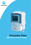
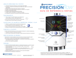
The Precision Flow® warms and humidifies a flow of breathing gas for delivery by nasal
cannula at flows from 1 to 40 lpm. The unit incorporates an electronic blender and flow
sensors that allow the oxygen percentage and total gas flow to be set independently
The Precision Flow® consists of two parts:
Main unit
• The main unit which contains all the electrical and electronic components including
the electronic blender and flow controllers, and sensors to monitor the disposable
water path.
• Flows of oxygen and air or heliox are regulated by proportional solenoid valves in
the gas metering manifold. The flows of oxygen and air or heliox are measured by
two mass flow sensors in the flow control manifold. Lookup
tables stored in the processor convert A-D units to flow in liters per minute. For any
setting of flow and oxygen percentage, the operating software calculates the target
flows for oxygen and air or heliox. The proportional solenoid valves are then
adjusted until the measured flow for each gas equals the target flow. The system
continually monitors the flows and makes small adjustments to the solenoid valves
as necessary to maintain the target flows. As a check on the mixing and metering
system, an oxygen cell continually reads a sample of the mixed gas. Alarms occur if
either flow cannot be adjusted to the target flow, if a mass flow sensor is out of
range, or if there is a discrepancy between the oxygen setting and the oxygen cell
reading.
• Firmware running in the main unit uses sensors to monitor gas pressure, water level
and water temperature, and air leaks in the water circuit (bubble detector). Alarms are
displayed if any parameters are outside the normal range. Other indicators include
backup battery charge, and the type of cartridge installed. See Mode Diagram for a
description of the firmware states and transitions.
• An internal battery backup will maintain the set flow and oxygen blend for at least
15 minutes without AC power. However, the circulating pump and heater will stop.
The battery is designed for temporary power loss, and is not intended for transport.
Disposable patient circuit
• The disposable patient circuit is comprised of the disposable water path, vapor
transfer cartridge and delivery tube. Conditions in the circulating water and gas
streams are sensed remotely via the interface between the main unit and the
disposable water path.
• Vapor transfer cartridge. In the cartridge blended gas passes through the lumens of
hundreds of parallel hollow fibers made of a specially developed polymer. Warm
water circulates around the fibers and diffuses as vapor through the fiber material
into the gas stream flowing through each fiber. There is no direct contact between
the water and gas streams. The gas stream leaves the cartridge essentially
saturated with vapor at the set temperature.
Note: Use only approved cartridges from Vapotherm Inc.
• Patient delivery tube. The warmed humidified gas passes through the center of a
triple-lumen heated delivery tube. The center lumen is surrounded by two outer
lumens carrying warmed water to maintain the temperature of the inner
lumen and to minimize rain-out. A proprietary short nasal cannula is connected to
the end of the delivery tube and passes the humidified breathing gas to the patient’s
nares.
1- 2
Technical Service Manual
3004005 Rev J