1
40MAQ / 38MAQ
High- Wall Ductless Split System
Sizes 09 to 30
Service Manual
TABLE OF CONTENTS
PAGE
SAFETY CONSIDERATIONS . . . . . . . . . . . . . . . . . . . . . . . . . 1
INTRODUCTION . . . . . . . . . . . . . . . . . . . . . . . . . . . . . . . . . . . 1
MODEL / SERIAL NUMBER NOMENCLATURE . . . . . . . . . 2
STANDARD FEATURES AND ACCESSORIES . . . . . . . . . . . 3
SPECIFICATIONS (HEAT PUMP ONLY UNITS) MAQ . . . . . 4
DIMENSIONS - INDOOR . . . . . . . . . . . . . . . . . . . . . . . . . . . . 5
DIMENSIONS - OUTDOOR . . . . . . . . . . . . . . . . . . . . . . . . . . 6
CLEARANCES - INDOOR . . . . . . . . . . . . . . . . . . . . . . . . . . . 9
CLEARANCES - OUTDOOR . . . . . . . . . . . . . . . . . . . . . . . . . 9
WIRING . . . . . . . . . . . . . . . . . . . . . . . . . . . . . . . . . . . . . . . . . . 10
CONNECTION DIAGRAMS . . . . . . . . . . . . . . . . . . . . . . . . . 11
WIRING DIAGRAMS . . . . . . . . . . . . . . . . . . . . . . . . . . . . . . . 12
FAN AND MOTOR SPECIFICATIONS . . . . . . . . . . . . . . . . . 17
SOUND DATA SPECIFICATION . . . . . . . . . . . . . . . . . . . . . . 17
REFRIGERATION CYCLE DIAGRAM . . . . . . . . . . . . . . . . . 21
REFRIGERANT LINES . . . . . . . . . . . . . . . . . . . . . . . . . . . . . 21
SYSTEM EVACUATION AND CHARGING . . . . . . . . . . . . . 22
CONTROL SYSTEM . . . . . . . . . . . . . . . . . . . . . . . . . . . . . . . 24
SEQUENCE OF OPERATION . . . . . . . . . . . . . . . . . . . . . . . . 25
MODES OF OPERATION . . . . . . . . . . . . . . . . . . . . . . . . . . . . 25
TROUBLESHOOTING . . . . . . . . . . . . . . . . . . . . . . . . . . . . . . 29
APPENDIX . . . . . . . . . . . . . . . . . . . . . . . . . . . . . . . . . . . . . . . 61
These words are used with the safety- alert symbol. DANGER
identifies the most serious hazards which will result in severe
personal injury or death. WARNING signifies hazards which could
result in personal injury or death. CAUTION is used to identify
unsafe practices which may result in minor personal injury or
product and property damage. NOTE is used to highlight
suggestions which will result in enhanced installation, reliability, or
operation.
WARNING
!
ELECTRICAL SHOCK HAZARD
Failure to follow this warning could result in personal
injury or death.
Before installing, modifying, or servicing system, main
electrical disconnect switch must be in the OFF
position. There may be more than 1 disconnect switch.
Lock out and tag switch with a suitable warning label.
!
EXPLOSION HAZARD
Failure to follow this warning could
result in death, serious personal injury,
and/or property damage.
Never use air or gases containing
oxygen for leak testing or operating
refrigerant compressors. Pressurized
mixtures of air or gases containing
oxygen can lead to an explosion.
SAFETY CONSIDERATIONS
Installing, starting up, and servicing air- conditioning equipment
can be hazardous due to system pressures, electrical components,
and equipment location (roofs, elevated structures, etc.).
Only trained, qualified installers and service mechanics should
install, start- up, and service this equipment.
Untrained personnel can perform basic maintenance functions such
as cleaning coils. All other operations should be performed by
trained service personnel.
When working on the equipment, observe precautions in the
literature and on tags, stickers, and labels attached to the
equipment.
Follow all safety codes. Wear safety glasses and work gloves. Keep
quenching cloth and fire extinguisher nearby when brazing. Use
care in handling, rigging, and setting bulky equipment.
Read this manual thoroughly and follow all warnings or cautions
included in literature and attached to the unit. Consult local building
codes and National Electrical Code (NEC) for special requirements.
Recognize safety information. This is the safety- alert symbol !! .
When you see this symbol on the unit and in instructions or manuals,
be alert to the potential for personal injury. Understand these signal
words: DANGER, WARNING, and CAUTION.
WARNING
!
CAUTION
EQUIPMENT DAMAGE HAZARD
Failure to follow this caution may result in equipment
damage or improper operation.
Do not bury more than 36 in. (914 mm) of refrigerant pipe
in the ground. If any section of pipe is buried, there must be
a 6 in. (152 mm) vertical rise to the valve connections on
the outdoor units. If more than the recommended length is
buried, refrigerant may migrate to the cooler buried section
during extended periods of system shutdown. This causes
refrigerant slugging and could possibly damage the
compressor at start- up.
INTRODUCTION
This Service Manual provides the necessary information to service,
repair, and maintain the 38- 40MA family of Puron air conditioners
and heat pumps. Section 2 of this manual has an appendix with data
required to perform troubleshooting. Use the Table of Contents to
locate a desired topic.
MODEL / SERIAL NUMBER NOMENCLATURES
Size
9
12
9
12
18
24
30
Voltage
Outdoor Model
38MAQB09---1
38MAQB12---1
38MAQB09---3
38MAQB12---3
38MAQB18---3
38MAQB24---3
38MAQB30---3
115/l/60
208-230/l/60
40
MA
Q
B
09
B
- -
Indoor Model
40MAQB09B--1
40MAQB12B--1
40MAQB09B--3
40MAQB12B--3
40MAQB18B--3
40MAQB24B--3
40MAQB30B--3
3
1 = 115/I/60
3 = 208 - 230 - 1 - 60Hz
40 = INDOOR UNIT
38 = OUTDOOR UNIT
NOT USED
MA =MODEL
UNIT TYPE
SYSTEM TYPE
Q = HEAT PUMP
B = HIGH - WALL
- = OUTDOOR
MAXIMUM NUMBER OF FAN COIL UNITS THAT
CAN BE CONNECTED TO THE OUTDOOR UNIT
B = 1:1
NOMINAL CAPACITY
09 - 3/4TON
12 - 1TON
18 - 1- 1/2TONS
24 - 2TONS
30 - 2- 1/2TONS
01
15
V
Week of Manufacture
10001
Sequential Serial Number
V = ALL MODELS
Year of Manufacture
Use of the AHRI Certified
TM Mark indicates a
manufacturer’s
participation in the
program For verification
of certification for individual
products, go to
www.ahridirectory.org.
2
STANDARD FEATURES AND ACCESSORIES
Ease Of Installation
Mounting Brackets
Low Voltage Controls
Comfort Features
Microprocessor Controls
Wired Remote Control
Wireless Remote Control
Automatic Horizontal Air Sweep
Air Direction Control
Auto Restart Function
Cold Blow Protection On Heat Pumps
Freeze Protection Mode On Heat Pumps
Turbo Mode
Silence Mode
Auto Changeover On Heat Pumps
Follow Me
Energy Saving Features
Sleep Mode
Stop/Start Timer
46° F Heating Mode (Heating Setback)
Safety And Reliability
3 Minute Time Delay For Compressor
Over Current Protection For Compressor
Indoor Coil Freeze Protection
Indoor Coil High Temp Protection in Heating Mode
Condenser High Temp Protection in Cooling Mode
Ease Of Service And Maintenance
Cleanable Filters
Diagnostics
Liquid Line Pressure Taps
Application Flexibility
Condensate Pumps
Crankcase Heater
Legend
S Standard
A Accessory
S
S
S
A
S
S
S
S
S
S
S
S
S
S
S
S
S
S
S
S
S
S
S
S
S
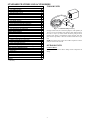
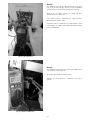
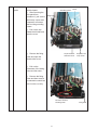
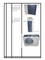
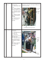
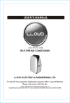
INDOOR UNITS
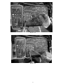
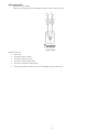
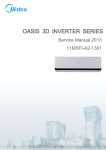
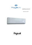
Fig. 1 – Condensate Pump Accessory
On high wall fan coils, the condensate pump has a lift capability of
12 ft (3.6 m) on the discharge side with the pump mounted in the
fan coil or 6 ft (1.8 m) on the suction side if the pump is remote
mounted. The pump is recommended when adequate drain line
pitch cannot be provided, or when the condensate must move up to
exit.
NOTE: An external 115v power source will be required to run the
pump on unit sizes 9k and 12k.
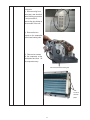
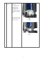
OUTDOOR UNITS
Crankcase Heater
Standard on all unit sizes. Heater clamps around compressor oil
stump.
A
S
3
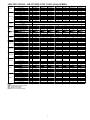
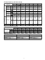
SPECIFICATIONS - HEAT PUMP ONLY UNITS (MAQ SERIES)
System
Performance
Controls
Operating
Range
Piping
Refrigerant
Refrigerant
Outdoor Coil
Indoor Coil
Compressor
Electrical
Outdoor
Indoor
Size
9
12
9
12
18
24
30
Outdoor Model
38MAQB09---1
38MAQB12---1
38MAQB09---3
38MAQB12---3
38MAQB18---3
38MAQB24---3
38MAQB30---3
Indoor Model
40MAQB09B--1 40MAQB12B--1 40MAQB09B--3 40MAQB12B--3 40MAQB18B--3 40MAQB24B--3
40MAQB30B--3
Energy Star
YES
YES
YES
YES
YES
YES
NO
Cooling Rated Capacity
Btu/h
9,000
12,000
9,000
12,000
17,500
23,000
30,000
Cooling Cap. Range Min - Max
Btu/h
3500~11000
4000~13000
3500~11000
4000~13000
4500~18000
5500~23500
8000~30500
SEER
23.5
21.5
23.5
21.5
19.5
20.0
16.5
EER
14.5
13
14.5
13
12.5
12.5
9.5
Heating Rated Capacity
Btu/h
10,000
12,000
10,000
12,000
18,000
25,000
32,000
Heating Cap. Range Min - Max
Btu/h
4,500~11,500
5,000~13,500
4,500~11,500
5,000~13,500
5,500~19,000
6,000~26,000
9,000~34,000
HSPF
10.0
10.0
10.0
10.0
9.6
10.0
9.6
COP
W/W
3.36
3.22
3.66
3.36
3.36
3.22
2.92
Wireless Remote Controller (°F/°C
Standard
Convertible)
Wired Remote Controller (°F/°C Convertible)
Optional
Cooling Outdoor DB Min - Max
°F
4~122
4~122
4~122
4~122
4~122
4~122
4~122
Heating Outdoor DB Min - Max
°F
4~86
4~86
4~86
4~86
4~86
4~86
4~86
Cooling Indoor DB Min -Max
°F
63~90
63~90
63~90
63~90
63~90
63~90
63~90
Heating Indoor DB Min -Max
°F
32~86
32~86
32~86
32~86
32~86
32~86
32~86
Total Piping Length
Ft.
82
82
82
82
98
98
164
Piping Lift*
Ft.
32
32
32
32
65
65
82
Pipe Connection Size - Liquid
In.
1/4
1/4
1/4
1/4
1/4
3/8
3/8
Pipe Connection Size - Suction
In.
3/8
1/2
3/8
1/2
1/2
5/8
5/8
Type
R410A
Design Pressure
PSIG
550
550
550
550
550
550
550
Metering Device
EEV
EEV
EEV
EEV
EEV
Capillary Tube
Capillary Tube
Charge
Lb.
2.76
2.76
2.76
2.76
4.19
5.18
6.62
Face Area
Sq. Ft.
9.2
9.2
9.2
9.2
16.0
21.1
17.2
No. Rows
2
2
2
2
2
3
3
Fins per inch
21
21
21
21
18
18
17
Circuits
4
4
4
4
6
8
6
Face Area (sq. ft.)
Sq. Ft.
2.2
2.2
2.2
2.2
2.6
3.7
3.7
No. Rows
2
2
2
2
2
3
3
Fins per inch
20
20
20
20
20
18
18
Circuits
3
3
3
3
4
7
7
Type
Hermetic Rotary DC Inverter Compressor
Model
ASM98D1UFZA ASM108D1UFZA ASM98D1UFZA ASM108D1UFZA ASM135D23UFZ DA250S2C-30MT TNB306FPGMC-L
Oil Type
VG74
VG74
VG74
VG74
VG74
VG74
FV50S
Oil Charge
Fl. Oz.
12.5
12.5
12.5
12.5
15.2
27.7
36.2
Rated Current
RLA
5.3
5.7
5.3
5.7
7.3
8.8
13.5
V/Ph/H
Voltage, Phase, Cycle
115-1-60
115-1-60
208/230-1-60
208/230-1-60
208/230-1-60
208/230-1-60
208/230-1-60
z
Power Supply
Indoor unit powered from outdoor unit
MCA
A.
15
15
15
15
15
15
20
MOCP - Fuse Rating
A.
20
20
15
15
20
25
30
Unit Width
In.
31.9
31.9
.9
31.9
33.3
37.2
37.2
Unit Height
In.
22.0
22.0
.0
22.0
.6
31.9
31.9
Unit Depth
In.
12.2
12.2
.2
12.2
.6
15.6
15.6
Net Weight
Lbs.
82.5
82.5
82.5
82.5
102.5
137.6
157.6
Airflow
CFM
1200
1200
1200
1200
1390
2130
2130
Sound Pressure
dB(A)
56
56
56
56
59
60
63
Unit Width
In.
32.9
32.9
32.9
32.9
39.0
46.7
46.7
Unit Height
In.
11.0
11.0
11.0
11.0
12.4
13.4
13.4
Unit Depth
In.
7.8
7.8
7.8
7.8
8.6
10.2
10.2
Net Weight
Lbs.
19.2
19.2
19.2
19.2
26.5
40.1
40.1
Number of Fan Speeds
4
4
4
4
4
4
4
Airflow (lowest to highest)
CFM 210/290/360/380 210/300/360/380 210/290/360/380 210/300/360/380 310/450/650/680 520/620/780/870 520/620/780/870
Sound Pressure (lowest to highest) dB(A)
27/34/42
27/34/42
27/34/42
27/34/42
33/40/46
39/45/50
39/45/50
Air throw Data
Ft.
23
23
23
23
30
36
36
Legend
SEER - Seasonal Energy Efficiency Ratio
EER - Energy Efficiency Ratio
MCA - Minimum Circuit Amps
MOCP - Max. Over-Current Protection
4
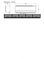
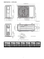
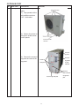
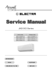
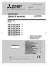
DIMENSIONS - INDOOR
Fig. 2 – Indoor units
Unit Size
W in (mm)
D in (mm)
H in (mm)
9K/12K
32.9 (835)
7.8 (198)
11.0 (280)
19.2 (8.7)
18K
39.0 (990)
8.6 (218)
12.4 (315)
26.5 (12.0)
24K/30K
46.7 (1186)
10.2 (258)
13.4 (343)
40.8 (18.5)
5
Operating Weight lb (kg)
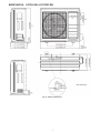
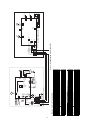
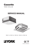
DIMENSIONS - OUTDOOR
Fig. 3 – Outdoor Unit Sizes 09 and 12
Operating
Weight lb (kg)
Model
W in (mm)
D1 in (mm)
H in (mm)
W1 in (mm)
D1 in (mm)
9K/12K
32.0 (810)
12.2 (310)
22.0 (558)
20.9 (530)
11.4 (290)
82.5 (37.4)
18K
33.2 (845)
13.2 (335)
27.6 (700)
22.1 (560)
13.2 (335)
102.5 (46.5)
24K
37.2 (945)
15.9 (405)
31.9 (810)
25.2 (640)
15.9 (405)
137.6 (62.4)
30K
37.2 (945)
15.9 (405)
31.9 (810)
25.2 (640)
15.9 (405)
157.6 (71.5)
6
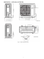
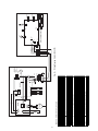
DIMENSIONS - OUTDOOR (CONTINUED)
Fig. 4 – Outdoor Units Size 18
7
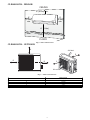
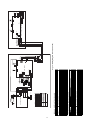
DIMENSIONS - OUTDOOR (CONTINUED)
Fig. 5 – Outdoor Units Size 24 and 30
8
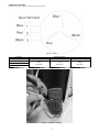
CLEARANCES - INDOOR
CEILING
6" (0.15m) min.
5"
(0.13m)
min.
5"
(0.13m)
min.
6' (1.8m)
FLOOR
Fig. 6 – Indoor Unit Clearance
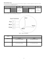
CLEARANCES - OUTDOOR
A
Air-inlet
E
D
B
C
Air-outlet
Fig. 7 – Outdoor Unit Clearance
Minimum Value
in. (mm)
24 (609)
24 (609)
24 (609)
4 (101)
4 (101)
UNIT
A
B
C
D
E
9
ELECTRICAL DATA
UNIT
SIZE
9K
12K
OPER. VOLTAGE
MAX / MIN*
127 / 104
COMPRESSOR
V/PH/HZ
115/1/60
RLA
5.3
5.7
OUTDOOR FAN
INDOOR FAN
MCA
MAX FUSE
CB AMP
20
15
20
V/PH/HZ
FLA
HP
W
V/PH/HZ
FLA
HP
W
115/1/60
0.14
0.053
40
115/1/60
0.17
0.027
9K
5.3
0.42
0.053
40
0.07
0.027
20
15
12K
5.70
0.42
0.053
40
0.07
0.027
20
15
0.95
0.067
50
0.17
0.077
58
15
20
24K
8.8
0.47
0.16
120
0.23
0.080
60
15
25
30K
13.5
1.21
0.16
120
0.23
0.080
60
20
30
18K
253 / 187
208-230/1/60
7.3
208-230/1/60
208-230/1/60
15
*Permissible limits of the voltage range at which the unit will operate satisfactorily.
LEGEND
FLA - Full Load Amps
MCA - Minimum Circuit Amps
RLA - Rated Load Amps
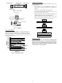
WIRING
Recommended Connection Method for Power and
Communication Wiring (To minimize communication wiring
interference)
Power Wiring:
The main power is supplied to the outdoor unit. The field supplied
connecting cable from the outdoor unit to indoor unit consists of
three (3) wires and provides the power for the indoor unit. Two
wires are high voltage AC power and one is a ground wire.
Consult your local building codes and the NEC (National
Electrical Code) or CEC (Canadian Electrical Code) for special
requirements.
All wires must be sized per NEC or CEC and local codes. Use
Electrical Data table MCA (minimum circuit amps) and MOCP
(maximum over current protection) to correctly size the wires and
the disconnect fuse or breakers respectively.
Per caution note, only copper conductors with a minimum 300 volt
rating and 2/64- inch thick insulation must be used.
Communication Wiring:
A separate shielded copper conductor only, with a minimum 300
volt rating and 2/64- inch thick insulation, must be used as the
communication wire from the outdoor unit to the indoor unit.
To minimize voltage drop of the control wire, the factory
recommendation is 14/3 wire with a ground. In special instances,
where there is high electrical interferences, use a separate 16ga
shielded wire to ensure proper communication.
The main power is supplied to the outdoor unit. The field supplied
connecting cable from the outdoor unit to indoor unit consists of four
(4) wires and provides the power and communication signals for the
indoor unit. Two conductors are for power wiring (L1/L2, or L/N),
one is a ground wire, and one is a DC communication wire.
Consult your local building codes and the NEC (National
Electrical Code) or CEC (Canadian Electrical Code) for special
requirements. All power wires must be sized per NEC or CEC and
local codes. Use Electrical Data table MCA (minimum circuit
amps) and MOCP (maximum over current protection) to correctly
size the wires and the disconnect fuse or breakers respectively.
Per caution note, only copper conductors with a minimum 300 volt
rating and 2/64- inch thick insulation must be used.
!
CAUTION
EQUIPMENT DAMAGE HAZARD
Failure to follow this caution may result in equipment
damage or improper operation.
S Wires should be sized based on NEC and local codes.
S Use copper conductors only with a minimum 300 volt
rating and 2/64 inch thick insulation.
!
CAUTION
EQUIPMENT DAMAGE HAZARD
Failure to follow this caution may result in equipment
damage or improper operation.
S Be sure to comply with local codes while running wire
from indoor unit to outdoor unit.
S Every wire must be connected firmly. Loose wiring
may cause terminal to overheat or result in unit
malfunction. A fire hazard may also exist. Therefore, be
sure all wiring is tightly connected.
S No wire should be allowed to touch refrigerant tubing
compressor or any moving parts.
S Disconnecting means must be provided and shall be
located within sight and readily accessible from the air
conditioner.
S Connecting cable with conduit shall be routed through
hole in the conduit panel.
10
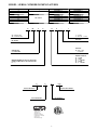
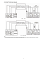
CONNECTION DIAGRAMS
Fig. 8 – 115V
Fig. 9 – 208- 230V
Notes:
1. Do not use thermostat wire for any connection between indoor and outdoor units.
2. All connections between indoor and outdoor units must be as shown. The connections are sensitive to polarity and will result in a fault code.
11
12
BLACK
RED
BLUE
CODE
CN1
CN15
CN16
CN19
CN31,CN33
CN32,CN34
CN26,CN28
CN4
CN5
CN6
CN7
CN8,CN9
CN36,CN37
N-B
UV W
RED
CN9
5($&725
RED
CN8
4
N-A
RY3
',6&+$5*(6(1625
CN15
+($7(;&+$1*(56(1625
%/$&.
INPUT or OUTPUT VALUE
Power Voltage :AC 115V
Power Voltage :AC115V
Relative to the N terminal voltage:DC 24V
Maximum voltage:DC5V
Indoor fan interface,Maximum voltage:DC310V
Stepper motor interface,Maximum voltage between the lines:DC12V
Ground
Room temperature sensor interface,maximum voltage:DC5V
Pipe temperature sensor interface,maximum voltage:DC5V
Display interface,maximum voltage between the lines:DC5V
PART NAME
Output:Pin5&6(12V) Pin1-Pin4:Pulse waveform,(0-12V)
Input:Pin1-Pin2(0-1.8V)
Input: Pin1,Pin3 ,Pin4,Pin5(0-1.8V)
Output:Pin1-Pin5(0-115V High voltage)
Output:115VAC High voltage
Output:115 VAC High voltage
Output:115 VAC for 4-way control
Input:115 VAC High voltage
Input:115 VAC High voltage
Connection to the earth
Output: Connection of the high voltage
Output: High voltage
Output: High voltage
Output: High voltage
Output: Pulse(0-320VDC)
OUTDOOR UNIT CONTROL BOARD
L_IN
CN11
CN16
CN15
CN4
CN5
P_1
CN8
CN9
CN10A
&$3$&,725
BLACK BLACK
L-A(CN37) L-B(CN36)
N-B
BLUE
CS
L2
0$,1
3&%
CN16
$0%,(176(1625
:+,7(
U
V
W 287'225
287'225:,5,1*',$*5$0
Y/G
&2035(6625
U
V
W
CN1
6(5)
EXPANSIVE VALVE
INDOOR UNIT CONTROL BOARD
Indoor Unit
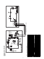
WIRING DIAGRAMS
287'225
)$1
5
CN10(CN19)
CN6
Y/G
BROWN
BLUE
CN4
CN5
1
6
/
Y/G
1
5('
%/8(
L N S
OUTDOOR UNIT
JX1
INDOOR UNIT
Y/G
RED
BLUE(BLACK)
YELLOW
Fig. 10 – Wiring Diagram Sizes 09- 12 (115V)
Power Input
Y/G
N
L
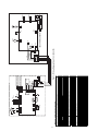
Dashed frame
parts only for heat
pump model.
HEATER, CRANKCASE
HEATER, CRANKCASE
L N S GND
/
:$<
YELLOW
BLACK
RED
BLACK
RED
CN7
CN26
CN28
CN34
CN33
CN32
CN31
CN16
N
CN2
P_1
INDOOR WIRING DIAGRAM
6
CN11
L-IN
CN4
5
M
,1)$1
6:,1*02725
8(7)
&1$
&1
CN5
M
&1
&1
',63/$<%2$5'
&1
&1
Wire Contoller
OPTIONAL
Wi-Fi
Contoller
OPTIONAL
3,3(7(03(5$785(6(1625
52207(03(5$785(6(1625
13
BLUE
BLACK
WHITE
WHITE
CN7
AMBIENT SENSOR
INPUT or OUTPUT VALUE
Output:Pin5&6(12V) Pin1-Pin4:Pulse waveform,(0-12V)
Input:Pin3-4 (3.3V) Pin2(0V),Pin1,Pin5(0-3.3V)
Input:Pin1 (3.3V) Pin2(0-3.3V)
Output: 230VAC High voltage
Output: Connection of the high voltage
Input:230VAC High voltage
Input:230 VAC High voltage
Connection to the earth
Output: Connection of the high voltage
Output: High voltage for 4-way control
Output: Pulse(0-320VDC) for DC FAN
Output: Pulse(0-320VDC) for COMPRESSOR
CN31
CN21
CN22
CN37
CN9-1,CN32-1
CN1
CN2
CN3
CN16
CN26,CN27
CN7
U V W
OUTDOOR UNIT CONTROL BOARD
Maximum voltage:DC5V
Indoor fan interface,Maximum voltage:DC310V
Stepper motor interface,Maximum voltage between the lines:DC12V
Ground
Room temperature sensor interface,maximum voltage:DC5V
Pipe temperature sensor interface,maximum voltage:DC5V
Display interface,maximum voltage between the lines:DC5V
Y/G
CN2
CN1
CN16
CN26
CN27
CN33
CN15
CN4
CN5
P_1
CN8
CN9
CN10A
CN3
CN31
INPUT or OUTPUT VALUE
Power Voltage :AC 230V
Power Voltage :AC230V
Relative to the N terminal voltage:DC 24V
DC-FAN
CN21
(/(&7521,&
(;3$16,9(
9$/9(
&21'(16(5
7(03(5$785(6(1625
L_IN
CN11
CN16
INDOOR UNIT CONTROL BOARD
REACTOR
CN32-1
CN22
DISCHARGE SENSOR
CN9-1
CN28 CN29 CN30
RED
COMPRESSOR
S
Y/G
L1 L2
RED
BLUE
YELLOW
L1 L2 S GND
L1 L2
BROWN
%/8(
RED
BLUE(BLACK)
YELLOW
CN11
N
L-IN
CN2
L1L2 S
OUTDOOR UNIT
JX1
INDOOR UNIT
Fig. 11 – Wiring Diagram Sizes 09- 12 (208- 230V)
Power Input
Y/G
L2
L1
Y/G
CN16
INDOOR WIRING DIAGRAM
6
CN4
HEATER, CRANKCASE
OPTIONAL:
:$<
5
M
,1)$1
HEATER, CRANKCASE
:$<
8(7)
&1$
&1
P_1
6:,1*02725
&1
&1
',63/$<%2$5'
CN5
M
&1
&1
Wire Contoller
OPTIONAL
Wi-Fi
Contoller
OPTIONAL
3,3( 7(03(5$785( 6(1625
52207(03(5$785(6(1625
14
RED
Y/G
BLUE
/ /
Y/G
CN6 CN6-1
/ / 6 / /
YELLOW
BLACK
CN8
CN7
CN2
CN3
CN4
&1 +($7
CN414
3
TEMPERATURE SENSOR
Maximum voltage:DC5V
Indoor fan interface,Maximum voltage:DC310V
Stepper motor interface,Maximum voltage between the lines:DC12V
Ground
Room temperature sensor interface,maximum voltage:DC5V
Pipe temperature sensor interface,maximum voltage:DC5V
Display interface,maximum voltage between the lines:DC5V
INPUT or OUTPUT VALUE
Input: 230V High voltage
Output: Connection of the high voltage
Output: High voltage for 4-way control
Output: 230V High voltage for HEATER
Output: Pulse(0-320V) for DC FAN
Output: Connection of the high voltage
Output: Pulse(0-320V) for compressor
Input:Pin1 (5V) Pin2(0-5V)
Input:Pin3-4 (5V) Pin2(0V),Pin1,Pin5(0-5V)
Output:Pin5&6(12V) Pin1-Pin4:Pulse waveform,(0-12V)
CN7、 CN8
CN2
CN3、 CN4
CN11、 CN16
CN5
CN12、 CN13
U V W
CN10
CN1
CN18
OUTDOOR UNIT CONTROL BOARD
CN13
BLACK
CN10
U
V
BLACK W
RED
BLUE
CN12
BLACK
RED
BLUE
Y/G
L1 L2 S
OUTDOOR UNIT
JX1
INDOOR UNIT
Y/G
RED
BLUE(BLACK)
YELLOW
Fig. 12 – Wiring Diagram Size 18 (208- 230V)
COMPRESSOR
U
5($&725
BLUE
BLUE
W V
1
2
3
&21'(16(5
',6&+$5*(6(1625
OUTDOORAMBIENT 7(03(5$785(6(1625
WHITE
CN1
CN14
CN15
CN4
CN5
P_1
CN8
CN9
CN10A
ELECTRONIC
EXPANSIVE
VALVE
6
CN18
OUTDOOR
MAIN
PCB
RY1
L-OUT
INPUT or OUTPUT VALUE
Power Voltage :AC 230V
Power Voltage :AC230V
Relative to the N terminal voltage:DC 24V
CN15
L_IN
CN11
CN16
INDOOR UNIT CONTROL BOARD
72,1'22581,7 32:(56833/<
Y/G
RED
HEATER 2
HEATER 1
4-WAY
OUT DOOR
FAN
CN16
N
CN2
INDOOR WIRING DIAGRAM
6
CN11
L-IN
CN4
5
M
,1)$1
8(7)
&1$
&1
P_1
CN5
M
&1
&1
',63/$<%2$5'
6:,1*02725
&1
&1
Wire Contoller
OPTIONAL
Wi-Fi
Contoller
OPTIONAL
3,3( 7(03(5$785( 6(1625
52207(03(5$785(6(1625
15
%/8(
%/8(
9
85
%/$&.
:&
:
<*
&2035(6625
96
%/8( 5('
8
&1 &1
,30%2$5'
&1
&1
5('
Display interface,maximum voltage between the lines:DC5V
INPUT or OUTPUT VALUE
Power Voltage :AC 230V
Power Voltage :AC230V
Relative to the N terminal voltage:DC 24V
Maximum voltage:DC5V
Maximum output voltage :AC230V
Indoor fan interface,Maximum voltage:DC310V
Stepper motor interface,Maximum voltage between the lines:DC12V
Ground
Room temperature sensor interface,maximum voltage:DC5V
Pipe temperature sensor interface,maximum voltage:DC5V
Display interface,maximum voltage between the lines:DC5V
Stepper motor interface (optional),maximum voltage between the lines:DC12V
L_IN
CN11
CN16
CN15
CN6
CN4
CN5
P_1
CN8
CN9
CN10A
CN14
OUTDOOR UNIT CONTROL BOARD
Y/G
Y/G
0$,1%2$5'
+($7
+($7
:$<
&1 &1 &1 &1 &1 &1
5<
&20
L-OUT
CN10A
%/8(
21
INPUT or OUTPUT VALUE
Power Voltage :AC 230V
Power Voltage :AC230V
Relative to the N terminal voltage:DC 24V
Maximum voltage:DC5V
Indoor fan interface,Maximum voltage:DC310V
Stepper motor interface,Maximum voltage between the lines:DC12V
Ground
Room temperature sensor interface,maximum voltage:DC5V
Pipe temperature sensor interface,maximum voltage:DC5V
2
1287
L_IN
CN11
CN16
CN15
CN4
CN5
P_1
CN8
CN9
INDOOR UNIT CONTROL BOARD
5($&725
&1
&1
a a
&1 :$<
& 1
&7
+($7(5
&1
RED
BL ACK
YELLOW
/ / 6 / /
BLACK
RED
BLUE(BLACK)
YELLOW
CN11
N
L-IN
CN2
M
,1)$1
OUTDOOR UNIT
JX1
INDOOR UNIT
Fig. 13 – Wiring Diagram Size 24 (208- 230V)
L1L2 S
Y/G
CN16
INDOOR WIRING DIAGRAM
6
CN4
1,1 S
&1 CN10
/ / S / /
RED
/,1
&1
'&)$1
5
',6&+$5*(6(1625
287'225$0%,(17
7 7(03(5$785(6(1625
7 &21'(16(5
7(03(5$785(6(1625
72,1'22581,7 32:(56833/<
*1'
3
&1
&1
5('
+($7(5
&1
&1
&1
%/8(
8(7)
&1$
&1
P_1
CN5
M
&1
&1
',63/$<%2$5'
6:,1*02725
&1
&1
Wire Contoller
OPTIONAL
Wi-Fi
Contoller
OPTIONAL
3,3( 7(03(5$785( 6(1625
52207(03(5$785(6(1625
U
T3
16
BLACK
RED
INPUT or OUTPUT VALUE
CN52
CN53
CN51
CN54
U
V
W
7
SV
L-PRO
T4
H-PRO
T3
HEAT2
Output: Pulse(0-380V) for compressor
U V W
INPUT or OUTPUT VALUE
Input: 230V High voltage
Output: Connection of the high voltage
Output: Pulse(0-320V) for DC FAN
Input:Pin1 (5V) Pin2(0-5V)
Output: High voltage for 4-way control
Output: 230V High voltage for HEATER1
Output: 230V High voltage for HEATER2
Input:Pin3-4 (5V) Pin2(0V),Pin1,Pin5(0-5V)
Input:Pin1~3 (0V) Pin2~4(0-5V)
Output: Connection of the high voltage
CN1、 CN2
S
CN11、 CN12
CN33
CN3、 CN22
CN4、 CN40
CN10、 CN44
CN8
CN9
CN51 CN52
7
The electric heating
belt of chassis
The electric heating
belt of compressor
HEAT1
WAY1
Power Voltage :AC 230V
Power Voltage :AC230V
Relative to the N terminal voltage:DC 24V
Maximum voltage:DC5V
Indoor fan interface,Maximum voltage:DC310V
Stepper motor interface,Maximum voltage between the lines:DC12V
Ground
Room temperature sensor interface,maximum voltage:DC5V
Pipe temperature sensor interface,maximum voltage:DC5V
Display interface,maximum voltage between the lines:DC5V
OUTDOOR UNIT CONTROL BOARD
L_IN
CN11
CN16
CN15
CN4
CN5
P_1
CN8
CN9
CN10A
INDOOR UNIT CONTROL BOARD
OUTDOOR AMBIENT
TEMPERATURE SENSOR
EXHAUST
TEMPERATURE SENSOR
CONDENSER
TEMPERATURE SENSOR
TP
T4
PFC INDUCTOR
4-WAY VALVE
SV
HIGH PRESSURE SWITCH
LOW PRESSURE SWITCH
L-PRO
H-PRO
L
CRANKCASE HEATING
FM1
HEAT
COMPRESSOR
COMP
OUTDOOR DC FAN
PART NAME
CODE
YELLOW
BLUE
BLUE
BLUE
RED
BLACK
CN10
CN4
CN3
CN9
YELLOW
L
BLUE
RED
BLACK
CN19
DRIVER BOARD
Y/G
W
COMP V
CN55
CN8
CN7
CN33
TP
CN5
S
L1 L2
5('
%/$&.
<(//2:
%/$&.
/ L2
5('
Y/G
RED
BLACK
YELLOW
<* 72,1'22581,7 32:(56833/<
-;,
P-1
CN1
CN2
S
CN11
L1L2 S
OUTDOOR UNIT
JX1
INDOOR UNIT
Y/G
RED
BLUE(BLACK)
YELLOW
Fig. 14 – Wiring Diagram Size 30 (208- 230V)
CN6
CN12
FM1
Applicable to the units
adopting DC motor only
Y/G
MAIN BOARD
RED
BLACK
CN44
CN40
CN22
L-IN
CN16
N
CN2
INDOOR WIRING DIAGRAM
6
CN11
CN4
5
M
,1)$1
8(7)
&1$
&1
P_1
CN5
M
&1
&1
',63/$<%2$5'
6:,1*02725
&1
&1
Wire Contoller
OPTIONAL
Wi-Fi
Contoller
OPTIONAL
3,3( 7(03(5$785( 6(1625
52207(03(5$785(6(1625
FAN AND MOTOR SPECIFICATIONS
9K
(115V)
Indoor fan motor
Outdoor fan
Indoor fan
System size
9K
(208-230 V)
12K
(208-230 V)
18K
(208-230 V)
24K
(208-230 V)
30K
(208-230 V)
material
AS
AS
AS
AS
AS
AS
AS
Type
GL-98*655-N
GL-98*655-N
GL-98*655-N
GL-98*655-N
GL-107.5*760-IN
GL-118*895-IN
GL-118*895-IN
Diameter
inch
98
98
98
98
107.5
118
118
Height
inch
655
655
655
655
760
895
895
material
AS
AS
AS
AS
AS
AS
AS
Type
ZL-421*117*8-3K
ZL-421*117*8-3K
ZL-421*117*8-3K
ZL-421*117*8-3K
ZL-460*180*10-3N
ZL-560*139*12-3KN
ZL-560*139*12-3KN
560
Diameter
inch
421
421
421
421
460
560
Height
inch
117
117
117
117
180
139
139
WZDK20-38M
DC
3
0.17
WZDK20-38M
DC
3
0.17
WZDK20-38G
DC
3
0.07
WZDK20-38G
DC
3
0.07
WZDK58-38G
DC
3
0.17
WZDK60-38G
DC
3
0.23
WZDK60-38G
DC
3
0.23
Model
Type
Phase
FLA
Insulation
class
Safe
class
Input
Output
Range of
current
Rated
current
Rated HP
Speed
Outdoor fan motor
12K
(115V)
Rated
RPM
Max.
input
Model
Phase
FLA
Type
Insulation
class
Safe
class
Input
Output
Range of
current
Rated
current
Rated HP
Speed
Rated
RPM
Max.
input
E
E
E
E
E
E
E
IPX0
IPX0
IPX0
IPX0
IPX0
IPX0
IPX0
W
W
25
20
25
20
22
20
22
20
52
58
72
60
72
60
Amps
0.17±10%
0.17±10%
0.07±10%
0.07±10%
0.17±10%
0.23±10%
0.23±10%
Amps
0.17
0.17
0.07
0.07
0.17
0.23
0.23
HP
rev/m
in
rev/m
in
0.027
0.027
0.027
0.027
0.077
1300/1170/900/700
1300/1170/900/700
1300/1170/900/700
1300/1170/900/700
1300/1170/900/700
0.08
1250/1200/1100/90
0
1350
1350
1350
1350
1350
W
0.08
250/1200/1100/900
1350
1350
25
25
22
22
52
72
72
WZDK40-38G-1
3
0.14
DC
WZDK40-38G-1
3
0.14
DC
WZDK40-38G-W-1
3
0.42
DC
WZDK40-38G-W-1
3
0.42
DC
ZKFN-50-8-2
3
0.95
DC
WZDK120-38G-1
3
0.47
DC
WZDK120-38G-W
3
1.21
DC
E
E
E
E
E
E
E
IPX0
IPX0
IPX0
IPX0
IPX0
IPX0
IPX0
W
W
42
40
42
40
46
40
46
40
116
50
145
120
150
120
Amps
0.14±10%
0.14±10%
0.42±10%
0.42±10%
0.95±10%
0.47±10%
1.21±10%
Amps
0.14
0.14
0.42
0.42
0.95
0.47
1.21
HP
rev/m
in
rev/m
in
0.053
0.053
0.053
0.053
0.067
0.16
0.16
800/700/600
800/700/600
800/700/600
800/700/600
800/700/600
850/750/700
850/800/750
900
900
900
900
900
1050
1050
42
42
46
46
116
145
150
W
SOUND DATA SPECIFICATION
System Size
9K
12K
(115V)
(115V)
9K
12K
18K
24K
30K
(208-230V) (208-230V) (208-230V) (208-230V) (208-230V)
Indoor Sound Pressure cooling mode (at different
speeds)
dBa
42/34/27
42/34/27
42/34/27
42/34/27
46.5/40/33
50/45/39
50/45/39
Indoor Sound Pressure heating mode (at different
speeds)
dBa
40/33/26
41/34/27
40/33/26
41/34/27
45/39/32
47/44/38
47/44/38
Outdoor sound pressure level
dBa
55.5
56
55.5
56
59
60
63
17
ENVIRONMENTAL SPECIFICATIONS
9K
(115V)
Non-operating
environment
Operating
Range
System size
12K
(115V)
Cooling
4-122
(-20-50)
63-90
(17-32)
59-84
(15-29)
Heating
4-86
(-20-30)
4-77
(-20-25)
32-86
(0-30)
9K
(208-230V)
12K
(208-230V)
18K
(208-230V)
24K
(208-230V)
30K
(208-230V)
4-122
(-20-50)
63-90
(17-32)
59-84
(15-29)
4-122
(-20-50)
63-90
(17-32)
59-84
(15-29)
4-122
(-20-50)
63-90
(17-32)
59-84
(15-29)
4-122
(-20-50)
63-90
(17-32)
59-84
(15-29)
4-122
(-20-50)
63-90
(17-32)
59-84
(15-29)
4-86
(-20-30)
4-77
(-20-25)
4-86
(-20-30)
4-77
(-20-25)
4-86
(-20-30)
4-77
(-20-25)
4-86
(-20-30)
4-77
(-20-25)
4-86
(-20-30)
4-77
(-20-25)
32-86 (0-30)
32-86 (0-30)
32-86 (0-30)
32-86 (0-30)
32-86 (0-30)
Outdoor Min Max DB
Indoor Min Max DB
Indoor Min Max WB
°F
(°C)
°F
(°C)
°F
(°C)
4-122
(-20-50)
63-90
(17-32)
59-84
(15-29)
Outdoor DB
Min – Max
Outdoor WB
Min – Max
Indoor DB Min
–Max
°F
(°C)
°F
(°C)
°F
(°C)
4-86
(-20-30)
4-77
(-20-25)
32-86
(0-30)
°F
32-86
(0-30)
32-86
(0-30)
32-86
(0-30)
32-86
(0-30)
32-86
(0-30)
32-86
(0-30)
32-86
(0-30)
(°C)
32-86
(0-30)
32-86
(0-30)
32-86
(0-30)
32-86
(0-30)
32-86
(0-30)
32-86
(0-30)
32-86
(0-30)
%
%
0-80 %
0-80 %
0-80 %
0-80 %
0-80 %
0-80 %
0-80 %
0-80 %
0-80 %
0-80 %
0-80 %
0-80 %
0-80 %
0-80 %
12K
(208-230V)
380
360
300
210
1200
18K
(208-230V)
680
650
450
310
1390
Temperature
range (DB)
Operation Humidity
Ambient Humidity
AIRFLOW SPECIFICATIONS
System size
Turbo
High
Medium
Low
Indoor (CFM)
Outdoor (CFM)
9K
(115V)
380
360
290
210
1200
12K
(115V)
380
360
300
210
1200
9K
(208-230V)
380
360
290
210
1200
24K
(208-230V)
870
780
620
520
2130
30K
(208-230V)
870
780
620
520
2130
AIR THROW DATA
Unit Capacity
Max. Approximate Air Throw ft. (m)
Approximate Air Throw ft.(m) range
9K,12K
23 (7)
11 (3.5) ~ 23 (7)
18K
30 (9)
13 (4) ~ 30 (9)
24K
36 (11)
16 (5) ~ 36 (11)
30K
36 (11)
16 (5) ~ 36 (11)
18
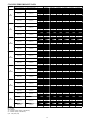
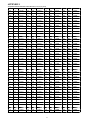
COOLING PERFORMANCE DATA
Model
Indoor Conditions DB
Cooling
Indoor Conditions WB
69.8F(21C)
59F(15C)
75.2F(24C)
62.6F(17C)
80.6F(27C)
66.2F(19C)
89.6F(32C)
73.4F(23C)
69.8F(21C)
59F(15C)
75.2F(24C)
62.6F(17C)
80.6F(27C)
66.2F(19C)
89.6F(32C)
73.4F(23C)
69.8F(21C)
59F(15C)
75.2F(24C)
62.6F(17C)
80.6F(27C)
66.2F(19C)
89.6F(32C)
73.4F(23C)
69.8F(21C)
59F(15C)
75.2F(24C)
62.6F(17C)
80.6F(27C)
66.2F(19C)
89.6F(32C)
73.4F(23C)
69.8F(21C)
59F(15C)
75.2F(24C)
62.6F(17C)
80.6F(27C)
66.2F(19C)
89.6F(32C)
73.4F(23C)
69.8F(21C)
59F(15C)
75.2F(24C)
62.6F(17C)
80.6F(27C)
66.2F(19C)
89.6F(32C)
73.4F(23C)
69.8F(21C)
59F(15C)
75.2F(24C)
62.6F(17C)
80.6F(27C)
66.2F(19C)
89.6F(32C)
73.4F(23C)
09
(115V)
12
(115V)
09
(208-230V)
12
(208-230V)
18
(208-230V)
24
(208-230V)
30
(208-230V)
TC
SC
Input
TC
SC
Input
TC
SC
Input
TC
SC
Input
TC
SC
Input
TC
SC
Input
TC
SC
Input
TC
SC
Input
TC
SC
Input
TC
SC
Input
TC
SC
Input
TC
SC
Input
TC
SC
Input
TC
SC
Input
TC
SC
Input
TC
SC
Input
TC
SC
Input
TC
SC
Input
TC
SC
Input
TC
SC
Input
TC
SC
Input
TC
SC
Input
TC
SC
Input
TC
SC
Input
TC
SC
Input
TC
SC
Input
TC
SC
Input
TC
SC
Input
77F(25C)
7.43
6.68
0.35
7.78
3.58
0.35
8.21
7.39
0.35
8.41
3.68
0.36
8.21
7.06
0.38
8.42
7.28
0.57
8.81
7.49
0.39
9.01
7.7
0.4
7.41
6.64
0.35
7.76
3.58
0.35
8.21
7.39
0.35
8.41
3.68
0.36
8.21
7.06
0.38
8.42
7.28
0.57
8.81
7.49
0.39
9.01
7.7
0.4
12.58
8.34
0.58
13.48
8.85
0.57
14.43
9.59
0.57
14.7
9.08
0.6
19.5
15.15
1.2
20.01
15.25
1.2
20.54
15.35
1.21
20.61
15.58
1.22
27.33
19.4
2.28
29.41
19.95
2.31
31.57
20.55
2.35
32.6
20.9
2.42
LEGEND
DB - Dry Bulb
WB - Wet Bulb
TC - Total Net Cooling Capacity (1000 Btu/hour)
SC - Sensible Capacity (1000 Btu/hour)
Input - Total power (kW)
19
86F(30C)
7.83
6.69
0.54
9.14
8.11
0.54
9.22
5.88
0.75
9.72
5.76
0.56
11.75
9.05
0.8
11.84
8.69
0.94
11.95
8.32
0.75
12.15
8.53
0.97
7.82
6.69
0.54
9.16
8.11
0.54
9.22
5.88
0.75
9.72
5.76
0.56
11.75
9.05
0.8
11.84
8.69
0.94
11.95
8.32
0.75
12.15
8.53
0.97
15.24
10.3
0.93
16.41
10.94
0.93
18.04
11.95
0.94
19.03
11.72
0.97
20.69
15.61
1.88
21.21
15.71
1.87
21.75
15.81
1.86
22.94
16.04
1.87
27.43
19.48
3.29
30.01
20.47
3.32
32.68
21.52
3.35
33.71
21.87
3.42
Outdoor conditions (DB)
95F(35C)
104F(40C)
9.74
8.38
8.18
7.37
0.81
0.8
9.89
8.65
6.27
5.52
0.81
0.8
10.41
9.27
8.22
7.79
0.82
0.81
11.59
10.22
6.9
6.2
0.83
0.82
11.42
9
8.68
7.38
1.04
0.87
12.01
9.35
8.66
7.62
1.25
1.27
12.23
9.69
8.63
7.85
1.06
0.89
12.43
9.89
8.84
8.06
1.3
1.34
9.73
8.34
8.18
7.37
0.81
0.8
9.89
8.62
6.27
5.52
0.81
0.8
10.41
9.27
8.22
7.79
0.82
0.81
11.59
10.22
6.9
6.2
0.83
0.82
11.42
9
8.68
7.38
1.04
0.87
12.01
9.35
8.66
7.62
1.25
1.27
12.23
9.69
8.63
7.85
1.06
0.89
12.43
9.89
8.84
8.06
1.3
1.34
16.25
11.04
10.6
7.93
1.53
1.2
16.66
12.3
11.35
8.62
1.56
1.22
18.37
13.35
12.37
9.28
1.59
1.24
20.18
15.36
12.5
9.69
1.62
1.27
21.43
18.05
15.49
14.23
2.29
2.14
22.31
18.51
15.59
14.33
2.3
2.21
23.21
18.98
15.69
14.43
2.31
2.26
24.4
21.84
15.92
14.66
2.34
2.33
27.51
22.77
19.56
17.21
3.63
3.11
29.82
24.53
20.07
17.73
3.68
3.17
32.21
26.37
20.65
18.3
3.74
3.23
33.24
27.4
21
18.65
3.81
3.3
113F(45C)
6.11
4.36
0.75
6.92
4.85
0.75
7.32
5.11
0.75
8.82
5.55
0.76
7.85
6.42
0.82
8.32
6.53
0.98
8.87
6.64
0.85
9.07
6.85
0.92
6.12
4.36
0.75
6.92
4.85
0.75
7.32
5.11
0.75
8.82
5.55
0.76
7.85
6.42
0.82
8.32
6.53
0.98
8.87
6.64
0.85
9.07
6.85
0.92
8.32
6.18
1.42
9.43
6.87
1.45
9.97
7.23
1.48
12.02
7.85
1.51
14.27
10.03
1.9
15.08
10.13
2.14
15.91
10.23
2.16
19.17
10.46
2.32
18.29
16.32
2.35
20.71
17.24
2.41
23.2
18.21
2.47
24.23
18.56
2.54
122F(50C)
5.11
3.74
0.75
5.83
4.29
0.75
6
4.37
0.75
7.51
5
0.77
6.68
5.58
0.81
7.34
5.81
0.94
7.95
6.04
0.82
8.15
6.25
0.85
5.1
3.74
0.75
5.83
4.29
0.75
6
4.37
0.75
7.51
5
0.77
6.68
5.58
0.81
7.34
5.81
0.94
7.95
6.04
0.82
8.15
6.25
0.85
6.78
5.16
1.32
7.74
5.91
1.35
7.96
6.02
1.38
9.97
6.89
1.41
13.32
8.78
1.86
13.3
8.88
1.92
13.3
8.98
1.93
16.66
9.21
1.96
17.32
15.28
2.25
18.24
16.29
2.31
19.21
17.35
2.38
20.24
17.7
2.45
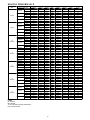
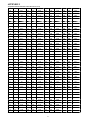
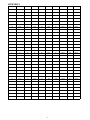
HEATING PERFORMANCE
Model
Heating
Outdoor conditions (DB)
Indoor Conditions DB
59F(15C)
64.4F(18C)
09(115V)
69F(20.5C)
71.6F(22C)
59F(15C)
64.4F(18C)
12(115V)
69F(20.5C)
71.6F(22C)
59F(15C)
64.4F(18C)
09
(208-230V)
69F(20.5C)
71.6F(22C)
59F(15C)
64.4F(18C)
12
(208-230V)
69F(20.5C)
71.6F(22C)
59F(15C)
64.4F(18C)
18
(208-230V)
69F(20.5C)
71.6F(22C)
59F(15C)
64.4F(18C)
24
(208-230V)
69F(20.5C)
71.6F(22C)
59F(15C)
64.4F(18C)
30
(208-230V)
69F(20.5C)
71.6F(22C)
53.6F(12C)
44.6F(7C)
39.2F(4C)
32F(0C)
24.8F(-4C)
19.4F(-7C)
17F(-8C)
5F(-15C)
TH
11.2
11.1
10.89
10.65
9.87
9.11
8.27
6.71
Input
0.73
0.79
1.04
1.01
0.96
0.9
0.84
0.8
TH
11.1
10.8
10.65
10.54
9.63
8.84
8.01
5.46
Input
0.78
0.8
1.08
1.03
0.98
0.94
0.9
0.82
TH
10.8
10.6
10.48
10.32
9.43
8.55
7.95
4.29
Input
0.8
0.81
1.11
1.05
1
0.98
0.96
0.84
TH
10.6
10.3
10.21
10.11
9.23
8.41
7.89
4.11
Input
0.82
0.83
1.15
1.07
1.02
1.02
0.92
0.86
TH
11.8
12.7
12.42
11.32
10.4
9.54
8.9
5.75
Input
0.79
1.01
1.05
1.1
1.02
1
0.98
0.83
TH
12.1
12.7
12.32
11.34
10.32
9.32
8.81
6.14
Input
0.83
1.37
1.4
1.26
1.22
1.27
1.01
0.91
TH
12.3
12.6
12.12
11.32
10.21
9.12
8.43
6.49
Input
0.83
1.1
1.12
1.19
1.19
1.25
1.03
0.98
TH
11.1
12.4
12.01
11.21
10.01
9.02
8.21
6.01
Input
0.85
1.15
1.16
1.21
1.23
1.31
1.05
1
TH
23.2
20.5
19.42
17.56
16.52
14.28
12.08
9.39
Input
1.58
1.49
1.48
1.58
1.46
1.4
1.35
1.21
TH
22.4
20.1
18.66
16.89
16.05
13.94
12.06
9.16
Input
1.62
1.55
1.55
1.61
1.52
1.45
1.4
1.29
TH
21.7
19.7
17.93
16.26
15.62
13.62
12.07
8.95
Input
1.67
1.62
1.63
1.65
1.58
1.5
1.45
1.38
TH
21
19
17.23
15.56
14.92
12.92
11.37
8.25
Input
1.72
1.67
1.68
1.7
1.63
1.55
1.5
1.43
TH
28.6
27.8
25.85
23.56
23.42
23.22
23.16
18.93
Input
2
2.25
2.24
2.21
2.2
2.23
2.24
2.17
TH
27.6
27.6
24.52
23.54
23.4
22.52
20.45
17.45
Input
2.24
2.45
2.35
2.35
2.32
2.23
2.21
2.16
TH
29.1
29.3
26.75
24.63
22.98
21.85
19.61
16.38
Input
2.39
2.74
2.64
2.58
2.42
2.25
2.2
2.18
TH
26.9
27.5
24.21
23.41
22.54
21.67
19.54
16.24
Input
2
2.25
2.24
2.21
2.2
2.23
2.24
2.17
TH
43
41.2
37.52
34.65
32.32
30.65
28.84
20.51
Input
3.79
3.99
3.69
3.43
3.2
2.96
2.82
2.61
TH
39.6
39.9
36.55
33.84
30.95
28.58
26.47
19.96
Input
3.35
4.23
3.85
3.65
3.24
3.11
3.04
2.76
TH
36.3
38.6
35.62
33.07
29.62
26.54
24.13
19.43
Input
3.45
4.46
4.01
3.9
3.31
3.2
3.16
2.89
TH
32.9
35.2
32.22
29.67
26.22
23.14
20.73
16.03
Input
3.68
4.69
4.24
4.13
3.54
3.43
3.39
3.12
LEGEND
DB - Dry Bulb
WB - Wet Bulb
TH - Total Net Heating Capacity (1000 Btu/hour)
Input - Total Power (kW)
20
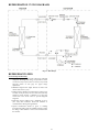
REFRIGERATION CYCLE DIAGRAMS
Fig. 15 – Heat Pumps
REFRIGERANT LINES
General refrigerant line sizing:
1 The outdoor units are shipped with a full charge of R410A
refrigerant. All charges, line sizing, and capacities are based
on runs of 25 ft (7.6 m). For runs over 25 ft (7.6 m), consult
long- line section on this page for proper charge
adjustments.
2 Minimum refrigerant line length between the indoor and
outdoor units is 10 ft. (3 m).
3 Refrigerant lines should not be buried in the ground. If it is
necessary to bury the lines, not more than 36- in (914 mm)
should be buried. Provide a minimum 6- in (152 mm)
vertical rise to the service valves to prevent refrigerant
migration.
4 Both lines must be insulated. Use a minimum of 1/2- in.
(12.7 mm) thick insulation. Closed- cell insulation is
recommended in all long- line applications.
5 Special consideration should be given to isolating
interconnecting tubing from the building structure. Isolate
the tubing so that vibration or noise is not transmitted into
the structure.
21
IMPORTANT: Both refrigerant lines must be insulated separately.
S
The following maximum lengths are allowed:
ft (m)
ft (m)
ft (m)
32(10)
32(10)
32(10)
32(10)
65(20)
65(20)
82(25)
ft (m)
26(8)
26 (8)
26(8)
26(8)
26(8)
26(8)
26(8)
ft (m)
82(25)
82 (25)
82(25)
82(25)
98(30)
98(30)
164(50)
Oz/ft
(g/m)
0.16(15)
0.16 (15)
0.16(15)
0.16(15)
0.16(15)
0.32(30)
0.32(30)
3/8 (9.52)
1/2 (12.7)
3/8 (9.52)
1/2 (12.7)
1/2 (12.7)
5/8 (16)
5/8 (16)
1/4 in
6.35
1/4 in
6.35
1/4 in
6.35
1/4 in
6.35
1/4 in
6.35
3/8 in
9.52
3/8 in
9.52
R410A
R410A
R410A
R410A
R410A
R410A
R410A
2.76(1.25)
2.76 (1.25)
2.76(1.25)
2.76(1.25)
4.19(1.90)
5.18(2.35)
6.62(3.00)
System size
Refrigerant
Piping
Min. Piping Length
Standard Piping Length
Max. outdoor-indoor
height difference
Max. Piping Length with
no additional refrigerant
charge
Max. Piping Length
Additional refrigerant
charge (between
Standard – Max piping
length)
Gas Pipe (size connection type)
Liquid Pipe (size connection type)
in
(mm)
in
(mm)
Refrigerant Type
Heat Pump Models
Charge Amount
REFIGERANT LINE LENGHTS ft. (m)
12K
9K
12K
(115V)
(208-230 V)
(208-230 V)
10 (3)
10 (3)
10 (3)
25 (7.5)
25 (7.5)
25 (7.5)
9K
(115V)
10 (3)
25 (7.5)
Lbs
(kg)
S
S
Above charge is for piping runs up to 25 ft. (7.6 m).
S
The outdoor unit (Sizes 09 - 18) has an electronic
expansion valve to manage the refrigerant flow of the
connected fan coil. Sizes 24 and 30 have capillary tube
metering devices in the outdoor unit.
For piping runs greater than 25 ft. (7.6 m), add
refrigerant up to the allowable length as specified below.
1 No change in line sizing is required.
2 Add refrigerant per table below.
9
12
18
24
30
Min
Max
Additional Charge, oz/ft.
ft (m)
10 - 25
>25 - 82
>82 - 164
(3 - 8)
(8 - 25)
(25 - 50)
82
10
98
164
None
0.16
0.32
30K
(208-230 V)
10 (3)
25 (7.5)
SYSTEM EVACUATION AND
CHARGING
!
CAUTION
UNIT DAMAGE HAZARD
Never use the system compressor as a vacuum pump.
ADDITIONAL CHARGE TABLE
Unit
Size
24K
(208-230 V)
10 (3)
25 (7.5)
Failure to follow this caution may result in equipment
damage or improper operation.
Long Line Applications,:
Total Line
Length ft
18K
(208-230 V)
10 (3)
25 (7.5)
0.32
3 Reduction in capacity due to long lines can be calculated
from the chart below.
Refrigerant tubes and indoor coil should be evacuated using the
recommended deep vacuum method of 500 microns. Always break
a vacuum with dry nitrogen.
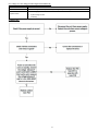
SYSTEM VACUUM AND CHARGE
Using Vacuum Pump
1 Completely tighten all flare nuts and connect manifold gage
charge hose to a charge port of the low side service valve.
(See Fig. 16.)
2 Connect charge hose to vacuum pump.
3 Fully open the low side of manifold gage. (See Fig. 17)
4 Start vacuum pump
5 Evacuate using the triple evacuation method.
6 After evacuation is complete, fully close the low side of
manifold gage and stop operation of vacuum pump.
7 The factory charge contained in the outdoor unit is good for
up to 25 ft. (8 m) of line length. For refrigerant lines longer
than 25 ft (8 m), add refrigerant as specified in the
ADDITIONAL REFRIGERANT CHARGE table in this
document.
8 Disconnect charge hose from charge connection of the low
side service valve.
9 Fully open service valves B and A.
10 Securely tighten caps of service valves.
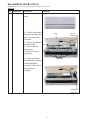
22
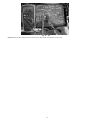
Indoor Unit
Refrigerant
Outdoor Unit
A
Low Side
B
High Side
C
D
Service Valve
Fig. 16 – Service Valve
Manifold Gage
500 microns
Low side valve
High side valve
Charge hose
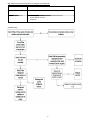
Triple Evacuation Method
The triple evacuation method should be used. Refer to Fig. 19 and
proceed as follows:
1 Pump system down to 500 MICRONS of mercury and
allow pump to continue operating for an additional 15
minutes.
2 Close service valves and shut off vacuum pump.
3 Connect a nitrogen cylinder and regulator to system and
open until system pressure is 2 psig.
4 Close service valve and allow system to stand for 10
minutes. During this time, dry nitrogen will be able to
diffuse throughout the system absorbing moisture.
5 Repeat this procedure as indicated in Fig. 19. System will
then be free of any contaminants and water vapor.
EVACUATE
Charge hose
BREAK VACUUM WITH DRY NITROGEN
Vacuum pump
WAIT
EVACUATE
Low side valve
BREAK VACUUM WITH DRY NITROGEN
Fig. 17 – Manifold
WAIT
Deep Vacuum Method
The deep vacuum method requires a vacuum pump capable of
pulling a vacuum of 500 microns and a vacuum gage capable of
accurately measuring this vacuum depth. The deep vacuum method
is the most positive way of assuring a system is free of air and
liquid water. (See Fig. 18)
EVACUATE
CHECK FOR TIGHT, DRY SYSTEM
(IF IT HOLDS DEEP VACUUM)
RELEASE CHARGE INTO SYSTEM
Fig. 19 – Triple Evacuation Method
5000
4500
4000
3500
3000
2500
2000
1500
1000
500
MICRONS
LEAK IN
SYSTEM
VACUUM TIGHT
TOO WET
Final Tubing Check
IMPORTANT: Check to be certain factory tubing on both
indoor and outdoor unit has not shifted during shipment.
Ensure tubes are not rubbing against each other or any sheet
metal. Pay close attention to feeder tubes, making sure wire ties
on feeder tubes are secure and tight.
TIGHT
DRY SYSTEM
0
1
2
3 4
5
MINUTES
6
7
Fig. 18 – Deep Vacuum Graph
23
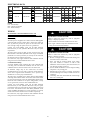
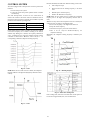
CONTROL SYSTEM
I3COOL, I2COOL, I1COOL mean different running current value.
The unit is equipped with a microprocessor control to perform two
functions:
1 Provide safety for the system
2 Control the system and provide optimum levels of comfort
and efficiency
The main microprocessor is located on the control board of
outdoor unit. Outdoor and indoor units have thermistors used to
monitor the system operation to maintain the unit within acceptable
parameters and control the operating mode.
Indoor fan speed
Maximum frequency
High speed/turbo function
No limit
Silent mode
Fixed
If users switch on AC by remote controller, the compressor will run
at the Fmax frequency for 7 minutes according to the outdoor
ambient temp. During the 7 minutes, the frequency limitation is
active. 7 minutes later, the compressor running frequency will be
controlled as shown below. While the zones of A, B, C… are
corresponding to different compressor running frequency.
S
S
Off: Compressor stops.
S
S
Hold: Keep the current frequency.
Decrease: Decrease the running frequency to the lower
level.
Resume: No limitation for frequency.
NOTE: When AC is in “hold” zone for 3 minutes, the compressor
frequency rises to the higher level. (Frequency increases twice at
most).
When T1- Ts stays in the same temperature zone for 3 minutes, the
compressor runs according to the following rules:
1 Increase the frequency to the higher level until F10.
2 Keep the current frequency.
3 Decrease the frequency to the lower level until F1.
4 Run at F1 for 1h.(if T1- Ts- T>42.8_F(6_C), the
compressor will stop).
Meanwhile, the compressor running frequency is limited by the
current.
Fig. 20 – Zones
NOTE: When AC is in “hold” zone for 3 minutes, the compressor
frequency will rise to the higher level.(frequency will increase twice
at most).
Fig. 22 – Running frequency
Fig. 23 – Indoor fan running rules
In the cooling mode, indoor fan runs all the time and the speed can
be selected as high, medium, low, auto and silent mode.
Fig. 21 – Zones
24
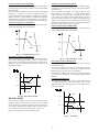
Evaporator Temperature Protection
The evaporator temperature protection function acts as follows:
— If the evaporator coil temperature (T2) is lower than
32_F (0_C), the compressor will stop and restarts once
—
Fig. 24 – Condenser temperature protection
T2 ≥ 41_F (5_C).
T2<32_F(0_C), the compressor will stop and restart
when T2≥41_F (5_C).
—
32_F(0_C)≤ T2<39.2_F(4_C), the compressor
frequency will be limited and decreased to the lower
level.
—
39.2_F (4_C)≤T2≤44.6_F(7_C), the compressor will
keep the current frequency.
T2>44.6_F(7_C), the compressor frequency will not be
limited.
—
—
If 32_F ≤ T2 <39_F (0_C ≤T2 <4_C), the compressor
frequency will be limited and decreased to a lower level.
—
Now, if 39_F ≤T2 <45_F (4_C ≤T2 <7_C), the
compressor continue running at the current frequency.
If T2>45_F (7_C), the compressor frequency will not be
limited, and operation is normal.
—
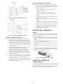
SEQUENCE OF OPERATION
Interface
Fig. 25 – Condenser temperature protection
Condenser temperature protection
The condenser temperature protection function acts as follows:
— If the condenser coil temperature (T3) is between 131_F
and 140_F (55C_<T3<60_C), the compressor frequency
will decrease to a lower level until it reaches the lowest
value, F1. It then runs at this F1 frequency. Once
T3<129_F (54_C), the compressor will continue running
at the current frequency.
— Condenser temperature protection (131_F(55_C ))<T3
<140_F(60_C)). The compressor frequency will
decrease to the lower lever until to F1 and then runs at
F1. If T3<129.2_F(54_C)), the compressor will keep
running at the current frequency. T3<125.6_F(52_C)),
the compressor will not limit the frequency and resume
to the former frequency.
— When the coil temperature reaches a value lower than
126_F (52_C), the compressor will not limit the
frequency and resumes to the required frequency.
— If T3>140_F (60_C) for 5 seconds, the compressor will
stop and restart once the coil temperature reaches a value
lower than 126_F (52_C).
A wireless remote control, supplied with the unit, is the interface
between the fan coil and the user. The wireless remote control has
the following characteristics:
S Capable of displaying _C and _F with _F being the default
setting. To change the default setting, refer to the Owner’s
Manual.
S The remote control setpoint range is from 62_F (17_C) to
86_F (30_C) in increments of 1_F (1_C).
S The wireless remote control has an operating range of 25 ft.
(7.62 m).
S The same remote control can be used to control more than one
unit.
S If the remote control is lost, damaged, or the batteries are
exhausted, the system can be operated by using the manual button
(forced Auto) located under the front panel.
Manual Button
AUTO/COOL
Fig. 26 – Manual Button Location on Unit
MODES OF OPERATION
COOLING MODE
In this mode, the system cools and dries the room air with the fan
running continuously, either at a selected fan speed or Auto fan
speed. The fan runs even when the compressor cycles off. This
feature enhances room comfort and efficiency of the system.
25
Compressor Operation in Cooling Mode:
In cooling mode, the maximum operation frequency (Fmax) of the
compressor, after it starts running, depends on the outdoor ambient
temperature (T4).
Once the system starts running, the compressor will run at the Fmax
frequency for 7 minutes at a specific T4. During this time, the
frequency limitation is active, therefore the compressor will continue
running even if the set point condition is satisfied. The compressor
running frequency will then be controlled based on the difference
between the room temperature and the temperature set point (T1- Ts).
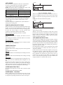
Outdoor Fan Operation in Cooling Mode:
When in cooling mode, the outdoor fan motor cycles based on the
outdoor ambient temperature as shown below:
Compressor Operation in Heating Mode
In heating mode, the maximum operation frequency (Fmax) of the
compressor, after it starts running, depends on the outdoor ambient
temperature (T4).
Once the system starts running, the compressor will run at the
Fmax frequency for 7 minutes at a specific outdoor ambient
temperature (T4). During this time, the frequency limitation is
active, therefore the compressor will continue running even if the
set point condition is satisfied. The compressor running frequency
will then be controlled based on the difference between the room
temperature, the temperature set point, and a temperature difference
that takes a default value of 32_F (T1- Ts- ΔT).
Outdoor Fan Operation in Heating Mode
When in heating mode, the outdoor fan motor cycles based on the
outdoor ambient temperature as shown below:
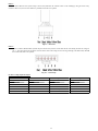
°F
°F
High
72
63
Low
68
Low
59
High
Fig. 27 – Outdoor Fan Motor Cycles
Indoor Fan Operation in Cooling Mode:
When in cooling mode, the indoor fan runs continuously either at
the chosen set speed (high, medium, or low), or in Auto mode,
where the speed is determined by the microprocessor based on the
difference between the room temperature and the temperature set
point as shown below:
4
High
3
Medium
1.5
Fig. 29 – Indoor Fan Motor Cycles
Indoor Fan Operation in Heating Mode
In heating mode, the indoor fan runs depending on the evaporator
coil temperature (T2).
If the set point conditions are satisfied and the compressor stops,
the indoor fan will be forced to run for two minutes with breeze.
During this period, the anti- cold- wind is disabled.
If the machine is running at the rated capacity test mode, the indoor
fan will run at the rated speed and the anti- cold- wind function is
disabled.
Auto Mode in Heating Mode
In heating mode, when the fan speed is set to Auto, the fan will run
at a speed determined by the microprocessor based on the
difference between the room temperature and the temperature set
point as shown below:
1
Low
Low
Fig. 28 – Indoor Fan Operation
2.5
HEATING MODE
2
In this mode, the system heats the room air with the indoor fan
running at either the selected speed or on Auto. As in the cooling
mode, the indoor fan will run continuously unless interrupted by
the cold blow algorithm. This algorithm will not allow the fan to
run if the indoor coil temperature drops below a preset value.
Defrost is controlled by the on- board microprocessor.
Medium
1.5
1
High
Fig. 30 – Auto Mode
26
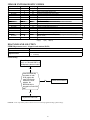
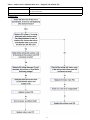
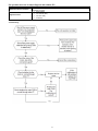
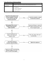
Defrost
Defrost on heat pump units is controlled by the microprocessor and
is initiated if either of the following conditions occur:
1 If the outdoor temperature, T4>32_F 0_C):
— The outdoor coil temperature (T3) has been lower than
37F (3 ) for about 40 minutes. During that time, the coil
temperature is lower than TCDI for more than 3 minutes.
2 If the outdoor temperature, T4<32_F 0_C):
— If the conditions described above are met, the program
judges if the evaporator coil temperature (T2) has
decreased more than 41F (5 ). When the evaporator
coil temperature has decreased more than 41F (5 ), the
defrost mode starts.
3 At any value of outdoor ambient temperature (T4):
— If the machine runs with a condenser coil temperature lower
than 37F (3 ) for more than 120 minutes and the outdoor
coil temperature (T3) has been lower than (TCDI+39F) for
more than 3 minutes, the machine enters the defrost mode.
Where: TCDI = - - 7C = 19.4F
Indoor fan running rules
Indoor fan speed can be set as high, medium, low, silent mode or
auto grade. During all the fan speeds, the anti- cold- wind function
is preferential. If the compressor stops caused by the room
temperature rising, the indoor fan will run at super breeze. When
the compressor is running, the indoor fan is controlled.
Outdoor fan running rules
In cooling mode the outdoor fan runs according to Fig 31.
Fig. 31 – Outdoor fan running rules
Condition of defrosting:
- - - - T4<32_F(0_C),
When the unit is running and the following two items are satisfied,
the unit starts defrosting. The units run with T3<37.4_F(3_C) for
40 minutes and T3 keeps lower than TCDI_F for more than 3
minutes. The units run with T3<37.4_F(3_C) for 80 minutes and
T3 keeps lower than TCDI 35.6_F(2_C) for more than 3 minutes.
- - - - T4 < 32_F(0_C).
If the 1st condition and 2nd condition items are satisfied, then the
program judges if T2 has decreased more than 41_F(2_C). When
T2 has decreased more than 41_F(2_C) enter the defrosting mode.
No matter what value T4 is, if the machine runs with T3
<37.4_F(3_C) for more than 120 minutes and T3 keeps lower than
TCDI+39.2_F(4_C) for more than 3 minutes, the machine will enter
defrosting mode no matter if T2 drops more than 41_F(5_C) or not.
Condition of ending defrosting:
If any one of the following items is satisfied, the defrosting will
finish and the machine will turn to normal heating mode.
- - - - T3 rises to be higher than TCDE 1_F
- - - - T3 keeps to be higher than TCDE 4_F for 80 seconds.
- - - - The machine has run for 10 minutes in defrosting mode.
Defrosting action:
Fig. 32 – 9k,12k, 18k, 24k, 30k models
XX=60s
Fig. 33 – 9k,12k, 18k, 24k, 30k models
Evaporator coil temperature protection
- - - - T2> TEH2_F, the compressor running frequency decreases to
the lower level and runs for 20s. When the frequency decreases to
F2 and the T2 is still over TEH 2_F for 3 minutes, the compressor
stops.
27
AUTO MODE
Set point
In the Auto mode, the temperature can be set to values between
62~86F (17~30 ). In this mode, the machine will choose
cooling, heating or fan- only mode according to ΔT.
NOTE: ΔT =T1- Ts, where T1 represents the indoor room
temperature and Ts represents the set temperature.
ΔT=T1- Ts
ΔT>2F
Running mode
Cooling
- 1<ΔT≤2F
Fan- only
Heating
ΔT≤- 2F
Indoor fan will run at an automatic fan speed for each running mode.
The louver will also operate depending in relevant mode taking place.
If the machine switches mode between heating and cooling, the
compressor will stop for 15 minutes and then choose a mode
according to ΔT.
If a new set temperature is commanded, the system will choose a
running mode according to ΔT.
FORCED OPERATION FUNCTION
When the machine is off, pressing the manual button will carry the
machine to forced auto mode. Pressing the button once again,
within 5 seconds, the machine will turn into forced cooling mode.
In forced auto, forced cooling or any other operation mode,
pressing the manual button will turn off the machine.
When in this mode, all general protections are available.
Forced cooling mode:
The compressor runs at F2 frequency and indoor fan runs as
breeze.
After running for 30 minutes, the machine will turn to auto mode
with a 75_F (24℃) set temperature.
Forced auto mode:
The action of forced auto mode is the same as normal auto mode
with a 75_F (24_C) set temperature.
TIMER FUNCTION
Timing range is 24 hours.
The timer function will not change the system’s current operation
mode.
The setting time is relative time.
Timer on
The machine will turn on automatically when reaching the set time.
Timer off
The machine will turn off automatically when reaching the setting
time.
Timer on/off
The machine will turn on automatically when reaching the set “on”
time, and then turn off automatically when reaching the set “off”
time.
The timer function will not change the AC current operation mode.
Suppose AC is off now, it will not start up first after setting the
“timer off” function. And when reaching the setting time, the timer
LED will turn off and the AC running mode will not change.
1.8°F (1°C)
1.8°F (1°C)
1
2
Time (hour)
Fig. 34 – Sleep Mode - Heating
When in heating mode, the set temperature decreases 1.8_F (1_C)
(down to a minimum 62_F (17_C)) every one hour. Two hours
later the set temperature stops rising and indoor fan is fixed at low
speed.
NOTE: Anti-cold wind function has the priority.
Set point
1.8°F (1°C)
1.8°F (1°C)
1
2
Time (hour)
Timer setting is available.
When the user uses timer off function in sleep mode (or sleep
function in timer off mode), if the timing is less than 7 hours, sleep
function will be cancelled when reaching the setting time. If the
timing is more than 7 hours, the machine will not stop until it
reaches the set time in sleep mode.
AUTO-RESTART FUNCTION
The indoor unit is equipped with auto-restart function, which is
carried out through an auto-restart module. In case of a sudden
power failure, the module memorizes the setting conditions present
previous to the power failure. The unit will automatically resume to
the previous operation settings (not including swing function) 3
minutes after the power returns.
If the memorization condition is forced cooling mode, the unit will
run in cooling mode for 30 minutes and turn to auto mode at a
75_F (24_C) set temp.
If unit is off before power off and unit is required to start up now,
the compressor will have 1 minute delay when power on. Other
conditions, the compressor will have 3 minutes delay when restarts.
If the equipment was off before the power went off, and it is
required to start up after this power failure, the compressor will
have a 1 minute delay when powering on. In other conditions, the
compressor will have a 3 minutes delay at re-start.
SLEEP MODE FUNCTION
Operation time in sleep mode is 7 hours. After 7 hours the system
turns off.
Operation process in sleep mode is as follow:
SLEEP MODE - COOLING
When in cooling mode, the set temperature rises 1.8_F (1_C) (up
to a maximum 86_F (30_C)) every one hour. Two hours later the
set temperature stops rising and indoor fan is fixed at low speed.
28
Follow me
1 If the indoor PCB receives the signal which results from
pressing the FOLLOW ME button on remote controller, the
buzzer will emit a sound and this indicates the follow me
function is initiated. But when the indoor PCB receives
signal which sent from remote controller every 3 minutes,
the buzzer will not respond. When the unit is running with
follow me function, the PCB will control the unit according
to the temperature from follow me signal, and the
temperature collection function of room temperature sensor
will be shielded, but the error detective function of room
temperature sensor will be still valid.
2 When the follow me function is available, the PCB will
control the unit according to the room temperature from the
remote controller and the setting temperature.
3 The PCB will take action to the mode change information
from remote controller signal, but it will not affected by the
setting temperature.
4 When the unit is running with follow me function, if the
PCB does not receive any signal from remote controller for
7 minutes or pressing FOLLOW ME button again, the
follow me function will be turned off automatically, and the
temperature will control the unit according to the room
temperature detected from its own room temperature sensor
and setting temperature.
Self Clean
For heat pump models which are provided with this function, after
running in cooling or drying mode, if the user press “Self Clean”
button on remote controller, indoor unit runs in fan only mode for
13 minutes, then low heat operation and finally in fan only again.
This function can keep the inside of indoor unit dry and prevent
breeding of mold.
Refrigerant Leakage Detection
With this new technology, the display area will show “EC” when
the outdoor unit detects refrigerant leakage. This feature is only
available in the cooling mode for 1 to 1 systems.
T2: indoor coil temp. Tcool: sample temp. of T2 when the
compressor starts. During the first 5 minutes after compressor’s
start, if the situation that T2 < Tcool- 3.6_ F does not last for 4
seconds continuously, the system will record suspected refrigerant
leakage once, and the compressor will stop.
If the above case happened three times continuously, the system
will judge refrigerant leakage. Indoor unit will indicate error code
“EC” and the unit will turn off automatically.
Refrigerant leakage count will reset under following situation:
During the first 5 minutes after compressor’s start, the situation that
T2 < Tcool- 3.6_ F lasts for 4 seconds continuously.
Evaporator anti- freeze protection in cooling mode.
Non- cooling mode.
Louver Position Memory Function
When starting the unit again after shutting down, its louver will
restore to the angle originally set by the user, but the precondition
is that the angle must be within the allowable range, if it exceeds, it
will memorize the maximum angle of the louver. During operation,
if the power fails the louver will restore to the default angle.
46_F (8_C) Heating (heating setback)
In heating operation, the preset temperature of the air conditioner
can be as low as 46_F, which keeps the room temperature steady at
46_F and prevents household pipes from freezing when the house
is unoccupied for a long time in severe cold weather.
Silence operation
Press the “silence” button on remote controller to initiate
SILENCE function. When the Silence function is activated, the
compressor running frequency will keep lower than F2 and the
indoor unit will supply faint breeze, which will reduce the noise to
the lowest level and create a quiet and comfortable room for you.
TROUBLESHOOTING
This section provides the required flow charts to troubleshoot
problems that may arise.
NOTE: Information required in the diagnoses can be found
either on the wiring diagrams or in the appendix.
Required Tools:
The following tools are needed when diagnosing the units:
S Digital multimeter
S Screw drivers (Phillips and straight head)
S Needle- nose pliers
S Refigeration gauges
Recommended Steps
1 Refer to the diagnostic hierarchy charts below and
determine the problem at hand.
2 Go to the chart listed in the diagnostic hierarchy and follow
the steps in the chart for the selected problem.
For the ease of service, the systems are equipped with diagnostic
code display LED’s on both the indoor and outdoor units. The
outdoor diagnostic display is on the outdoor unit board and is
limited to very few errors. The indoor diagnostic display is a
combination of flashing LED’s on the display panel on the front of
the unit. If possible always check the diagnostic codes displayed on
the indoor unit first.
The diagnostic codes for the indoor and outdoor units are listed in
the appendix.
Problems may occur that are not covered by a diagnostic code, but
are covered by the diagnostic flow charts. These problems will be
typical air conditioning mechanical or electrical issues that can be
corrected using standard air conditioning repair techniques.
For problems requiring measurements at the control boards, note
the following:
1 Always disconnect the main power.
2 When possible check the outdoor board first.
3 Start by removing the outdoor unit top cover.
4 Reconnect the main power
5 Probe the outdoor board inputs and outputs with a digital
multi- meter referring to the wiring diagrams.
6 Connect the red probe to hot signal and the black probe to
the ground or negative.
7 Note that some of the DC voltage signals are pulsating
voltages for signal. this pulse should be rapidly moving at
all times when there is a signal present.
8 If it is necessary to check the indoor unit board you must
start by disconnecting the main power.
9 Next remove the front cover of the unit and then control
box cover.
10 Carefully remove the indoor board from the control box,
place it face up on a plastic surface (not metal).
11 Reconnect the main power and repeat steps 5,6, and 7.
12 Disconnect main power before reinstalling board to avoid
shock hazard and board damage.
29
INDOOR UNIT DIAGNOSTIC GUIDES
Operation lamp
1 time
2 times
3 times
4 times
5 times
6 times
7 times
2 times
3 times
4 times
5 times
6 times
1 times
2 times
Timer lamp
X
Display
E0
LED STATUS
Indoor unit EEPROM parameter error
X
E1
Indoor / outdoor units communication error
X
E2
Zero-crossing signal detection error
X
E3
Indoor fan speed has been out of control
X
E4
Indoor room temperature sensor T1 open circuit or short circuit
X
E5
Evaporator coil temperature sensor T2 open circuit or short circuit
X
EC
Refrigerant leakage detection
O
F1
Outdoor ambient temperature sensor T4 open circuit or short circuit
O
F2
Condenser coil temperature sensor T3 open circuit or short circuit
O
F3
Compressor discharge temperature sensor T5 open circuit or short circuit
O
F4
Outdoor unit EEPROM parameter error
O
F5
Outdoor fan speed has been out of control
P0
IPM malfunction or IGBT over-strong current protection
P1
3 times
P2
5 times
P4
Over voltage or over low voltage protection
High temperature protection of compressor top diagnosis and solution (only for
9k,12k models)
Inverter compressor drive error
O(light)
X(off)
(flash)
DIAGNOSIS AND SOLUTION
EEPROM parameter error - diagnosis and solution (E0/F4)
Error Code
Malfunction decision conditions
Supposed Causes
E0/F4
Indoor or outdoor PCB main chip does not receive feedback from EEPROM chip.
S
S
Installation mistake
PCB faulty
Trouble shooting:
Shut off the power supply and
turn it on 5 seconds later. Is it
still displaying the error code?
Yes
If the EEPROM chip
is welded on main
PCB, replace the
main PCB directly.
Otherwise, check
whether the
EEPROM chip is
plugged into main PCB
well.
No
Correct the connection.
Yes
Replace the main PCB.
EEPROM: a read- only memory whose contents can be erased and reprogrammed using a pulsed voltage.
30
Indoor / outdoor unit’s communication error - diagnosis and solution (E1)
Error Code
E1
Malfunction decision conditions
Indoor unit does not receive feedback from outdoor unit in 110 seconds, and this condition occurs
four times continuously.
Supposed Causes
Indoor and outdoor unit communications fault
Troubleshooting:
31
Remark
Use a multimeter to test the DC voltage between the L2 port and S
ports of the outdoor unit. (Fig. 35) The red pin of multimeter
connects with the L2 port while the black pin is for the S port.
When the AC is running normally, the voltage will move
alternatively between - 50V to 50V.
If the outdoor unit has a malfunction, the voltage will move
alternatively with a positive value.
If the indoor unit has a malfunction, the voltage will be a certain
value. Example: 10- 13VDC small fluctuating amounts indicates
indoor unit malfunction.
Fig. 35 – DC voltage test
Remark
Use a multimeter to test the resistance of the reactor which does not
connect with the capacitor (Fig. 36).
The normal values should be around zero ohm.
Otherwise, the reactor must has a malfunction and must be
replaced.
Fig. 36 – Reactor resistance test
32
Zero crossing detection error diagnosis and solution (E2)
Error Code
E2
Malfunction
decision conditions
When PCB does not receive zero crossing
signal feedback for 4 minutes or the zero
crossing signal interval is abnormal
Supposed
Causes
S
S
Connection mistake
PCB faulty
Troubleshooting:
33
Fan speed has been out of control diagnosis and solution (E3)
Error Code
Malfunction decision conditions
Supposed Causes
E3
When the indoor fan speed is too slow (300 RPM) for a certain time, the unit will stop and the LED
will display the failure.
S Wiring mistake
S
S
S
Fan assembly faulty
Fan motor faulty
PCB faulty
Troubleshooting:
34
Index 1:
Indoor or outdoor DC fan motor (control chip is in fan motor) Measure the resistance value of each winding by using the tester. If any
resistance value is zero, the fan motor must have problems and needs to be replaced.
Fig. 37 – Fan motor
Index 2:
1 Indoor or Outdoor DC Fan Motor (control chip is in the fan motor). Power on and when the unit is in standby, measure the voltage of
pin- 1 - pin3, pin4- pin3 in the fan motor connector. If the value of the voltage is not in the range showing in the table below, the PCB
has an issue and needs to be replaced.
Fig. 38 – Control chip
DC motor voltage input and output
No.
1
Color
Red
Signal
Vs/Vm
Voltage
280V- 380V
2
---
---
---
3
Black
GND
OV
4
White
Vcc
14- 14.5V
5
Yellow
Vsp
0~5.6V
6
Blue
FG
14- 17.5V
35
2 Outdoor DC Fan Motor (control chip is in the outdoor PCB)
Fig. 39 – Outdoor DC Fan Motor
No.
1
2
3
4
5
Color
Orange
Grey
White
Pink
Black
Signal
Hu
Hv
Hw
Vcc
GND
Color
Red
Blue
Yellow
Signal
W
V
U
1 Release the UVW connector. Measure the resistance of U- V, U- W, V- W. If the resistance is not equal to each other, the fan motor has
an issue and needs to be replaced. Otherwise, proceed to step 2.
2 Power on and when the unit is in standby, measure the voltage of pin 4- 5 in the feedback signal connector. If the value is not 5V,
change the PCB. Otherwise proceed to step 3.
3 Rotate the fan by hand, measure the voltage of pin 1- 5, pin 2- 5, and pin 3- 5 in the feedback signal connector. If any voltage is not
positive voltage fluctuation, the fan motor has an issue and must be replaced.
36
Open circuit or short circuit of temperature sensor diagnosis and solution (E5)
Error Code
E5
Malfunction decision conditions
If the sampling voltage is lower than 0.06V or higher than 4.94V, the LED will display the failure.
Supposed Causes
S
S
Wiring mistake
Sensor faulty
Troubleshooting:
37
Fig. 40 – Test
38
Refrigerant Leakage Detection Diagnosis and Solution (EC)
Error Code
EC
Malfunction decision conditions
Define the evaporator coil temp.T2 of the compressor just starts running as Tcool. In the beginning 5
minutes after the compressor starts up, if T2 <Tcool-35.6°F(Tcool-2°C) does not keep continuous 4
seconds and this situation happens 3 times, the display area will show “EC” and AC will turn off.
Supposed caused
S
S
S
T2 sensor faulty
Indoor PCB faulty
System problems, such as leakage or blocking
Troubleshooting
39
IPM malfunction or IGBT over- strong current protection diagnosis and solution (PO)
Error Code
PO
Malfunction decision conditions When the voltage signal that IPM sends to the compressor drive chip is abnormal, the LED display will show
“PO” and the AC will turn off.
Supposed causes
S
S
S
S
S
Wiring mistake
IPM malfunction
Outdoor fan assembly faulty
Compressor malfunction
Outdoor PCB faulty
NOTE: In figures 41- 46 the following is observed:
S
S
S
U,V,W references compressor connection point
P references input voltage
N references output voltage
40
Fig. 41 – P- U
Fig. 42 – P- V
41
Fig. 43 – P- W
Fig. 44 – N- U
42
Fig. 45 – N- V
Fig. 46 – N- W
43
Over voltage or too low voltage protection diagnosis and solution (P1)
Error Code
P1
Malfunction decision conditions An abnormal voltage rise or drop is detected by checking the specified voltage detection circuit.
Supposed causes
S
S
S
Power supply problems
System leakage or block
PCB faulty
Troubleshooting:
44
Fig. 47 – Test
NOTE: Measure the DC voltage between the P and N ports. The normal value should be around 310V.
45
High temperature protection of compressor top diagnosis and solution (P2)
Error Code
P2
Malfunction decision conditions If the sampling voltage is not 5V, the LED will display the failure.
Supposed causes
S
S
S
Power supply problems
System leakage or block
PCB faulty
Troubleshooting
46
Inverter compressor drive error diagnosis and solution(P4)
Error Code
P4
Malfunction decision conditions An abnormal inverter compressor drive is detected by a special detection circuit, including communication
signal detection, voltage detection, compressor rotation speed signal detection and so on.
Supposed causes
S
S
S
S
S
Wiring mistake
IPM malfunction
Outdoor fan assembly fault
Compressor malfunction
Outdoor PCB faulty
47
Main parks check
1 Temperature sensor checking
Disconnect the temperature sensor from PCB, measure the resistance value with a tester.
Fig. 48 – Tester
Temperature sensors.
S Room temp.
S
S
S
S
S
(T1) sensor, Indoor coil temp.
(T2) sensor, Outdoor coil temp.
(T3) sensor, Outdoor ambient temp.
(T4) sensor, Compressor discharge temp.
(T5) sensor. Measure the resistance value of each winding by using the multi- meter.
48
Compressor checking
Measure the resistance value of each winding by using the tester.
Fig. 49 – Tester
Terminal
Resistance Value
Terminal one
Blue - Red
Blue - Black
Red - Blue
Terminal two
Terminal three
0.8Ω
1.77Ω
0.55Ω
(68°F/20°C)
(68°F/20°C)
(68°F/20°C)
Fig. 50 – Compressor checking
49
IPM continuity check
Turn off the power, let the large capacity electrolytic capacitors discharge completely, and dismount the IPM. Use a digital tester to measure
the resistance between P and UVWN; UVW and N.
Normal resistance
value
Digital tester
(+)Red
P
(-)Black
(+)Red
N
U
U
∞
V
(Several MΩ)
Normal resistance
value
Digital tester
V
W
W
(-)Black
∞
N
(Several MΩ)
(+)Red
Indoor AC Fan Motor
Measure the resistance value of each winding by using the tester.
Fig. 51 – Indoor AC Fan Motor
Resistance Value
Terminal
Black - Red
White ‐ Black
100.5Ω±8%
(20°C /68°F) (Brand: Weiling)
100Ω±8%
(20°C /68°F) (Brand: Dayang)
64.5Ω±8%
68.5Ω±8%
(20°C /68°F) (Brand: Weiling)
(20°C /68°F) (Brand: Dayang)
50
DISASSEMBLY INSTRUCTIONS
NOTE: This part is for reference only and the photos may differ from your unit.
Indoor unit
No.
Parts name
Procedures
Remarks
1
Front panel
How to remove the front
panel.
Overview:
1) Pull the bottom side of
the panel and release the
clips. Then remove the
front panel.
2) Remove the filter and
horizontal louver.
3) Remove the four
fixing screws.
4) Remove the cover
(one screw).
Panel
One screw
fixing the cover
Clip
Clip
Filter
5) Lift the panel frame
and release the connector
of display assembly.
’
connectors. Then remove
the panel frame
assembly.
Four screws
Connector for
display ass’y
51
2
Electrical
parts
How to remove the
electrical parts.
1) After removing the
front panel from
procedure 1, pull out the
room temp. sensor and
evaporator coil sensor.
Remove the grounding
screws.
2) Pull out the clip
toward the left side and
open the cover.
Room temp.
Grounding screws
sensor
Swing motor
3) Remove the fixing
screw and open the
electrical box cover.
.
Clip for electronic
Evaporator coil
control box cover
temp. sensor
4) Pull out the
connectors of the swing
motor and fan motor .
5) Remove the fixing
screw and then remove
the electronic control box
and air outlet assembly.
Fan motor connector
and swing motor
52
Fixing screw
3
Evaporator
How to remove the
evaporator.
1) After removing front
panel ass’y and electrical
parts following procedure
1 and procedure 2,
remove the pipe holder at
the rear side of the unit.
2) Remove the two
screws on the evaporator
at the base bearing side.
3) Remove two screws
on the evaporator at the
fixed plates and then lift
the evaporator ass’y.
Two screws at the base bearing side
Two
screws at
the fixed
plates
53
4
Fan and
motor
How to remove the fan
and motor.
1) After remove the
evaporator ass’y
following procedure 1,
procedure 2 and
procedure 3, remove the
three screws fixing the
cover
2) Remove the screw
fixing the motor and then
pull out the motor.
Three screws
One screw
54
OUTDOOR UNIT
No.
Part name
Procedures
1
Panel plate
How to remove the panel
plate.
1) Stop operation of the
air conditioner and turn
“OFF” the breaker.
Remarks
2) Refer to the photos on
the right to locate screws
on the panels.
Screw of
top panel
3) Remove the screws of
top panel and remove the
top panel.
Screws of
Screws of
big handle
front panel
on right
side plate.
Screws of
water connector
on right side
Screw of right side plate
plate
55
Screw of
the top
4) Remove the screws of
the front panel, including
the fixing screws of motor
holder and then remove
the front panel.
panel
Screws of right rear plate
5) Remove the screws of
the right side plate and
remove the right side
plate.
Screw of
top panel
Screws of front panel
56
2
Fan ass’y
How. to remove the fan
assembly
Electronic control box
Fan ass’y
1) After removing the
panel plate following
procedure 1, remove the
hex nut fixing the fan and
then remove the fan.
Reactor
Compressor and liquid-gas separator
Nut fixing the fan
2) Unfix the hooks and
then open the electronic
control box cover.
57
Fan motor connector
3) Disconnect the
connector for fan motor
from the electronic control
board.
4) Remove the four
fixing screws of the fan
motor.
5) Then remove the fan
motor.
3
Electrical
parts
Four
screws
How to remove the
electrical parts.
1) After finish work of
item 1 and item 2, remove
the three connectors for
the compressor and
electrical heaters.
Reactor connector
Compressor
connector and
2) Release the
connector of the reactor.
electrical heater
connector
Two blue wires of four way valve
58
3) Pull out the two blue
wires connected with the
four way valve.
4) Pull out connectors of
the compressor top temp.
sensor, condenser coil
temp. sensor(T3),outdoor
ambient temp. sensor(T4)
and discharge temp.
sensor(T5).
Four connectors of temp. sensors.
5) Remove the ground
wires .
6) Remove the power
supply wires(L1,L2,S).
7) Then remove the
electronic control box.
59
4
Four-way
valve
How to remove the
four-way valve.
1) Perform work of item
1,2,3.
2) Recover refrigerant
from the refrigerant circuit.
3) Remove the screw of
the coil and then remove
the coil.
4) Detach the welded
parts of four-way valve
and pipe.
5) Then the four-way
valve ass’y can be
removed
The picture of four-way valve may be different from
the one on your side.
Four-way
valve
Welded
parts
Coil of four-way valve, fixing by one screw.
5
Compressor
How to remove the
compressor.
1) After performing work
of item 1,2,3.
2) Remove the
discharge pipe and suction
pipe with a torch.
3) Remove the hex nuts
and washers fixing the
compressor on bottom
plate.
4) Lift the compressor
from the base pan
assembly.
Discharge
pipe and
suction
pipe
Nuts of
compress
60
APPENDIX 1
Temperature Sensor Resistance Value Table for T1, T2, T3, T4 (°C--K)
°C
°F
K Ohm
°C
°F
K Ohm
°C
°F
K Ohm
°C
°F
K Ohm
‐20
-4
115.266
20
68
12.6431
60
140
2.35774
100
212
0.62973
‐19
-2
108.146
21
70
12.0561
61
142
2.27249
101
214
0.61148
‐18
0
101.517
22
72
11.5
62
144
2.19073
102
216
0.59386
‐17
1
96.3423
23
73
10.9731
63
145
2.11241
103
217
0.57683
‐16
3
89.5865
24
75
10.4736
64
147
2.03732
104
219
0.56038
‐15
5
84.219
25
77
65
149
1.96532
105
221
0.54448
‐14
7
79.311
26
79
9.55074
66
151
1.89627
106
223
0.52912
‐13
9
74.536
27
81
9.12445
67
153
1.83003
107
225
0.51426
‐12
10
70.1698
28
82
8.71983
68
154
1.76647
108
226
0.49989
‐11
12
66.0898
29
84
8.33566
69
156
1.70547
109
228
0.486
‐10
14
62.2756
30
86
7.97078
70
158
1.64691
110
230
0.47256
-9
16
58.7079
31
88
7.62411
71
160
1.59068
111
232
0.45957
-8
18
56.3694
32
90
7.29464
72
162
1.53668
112
234
0.44699
-7
19
52.2438
33
91
6.98142
73
163
1.48481
113
235
0.43482
-6
21
49.3161
34
93
6.68355
74
165
1.43498
114
237
0.42304
-5
23
46.5725
35
95
6.40021
75
167
1.38703
115
239
0.41164
-4
25
36
97
6.13059
76
169
1.34105
116
241
0.4006
-3
27
41.5878
37
99
5.87359
77
171
1.29078
117
243
0.38991
-2
28
39.8239
38
100
5.62961
78
172
1.25423
118
244
0.37956
-1
30
37.1988
39
102
5.39689
79
174
1.2133
119
246
0.36954
0
32
35.2024
40
104
5.17519
80
176
1.17393
120
248
0.35982
1
34
33.3269
41
106
4.96392
81
178
1.13604
121
250
0.35042
2
36
31.5635
42
108
4.76253
82
180
1.09958
122
252
0.3413
3
37
29.9058
43
109
4.5705
83
181
1.06448
123
253
0.33246
4
39
28.3459
44
111
4.38736
84
183
1.03069
124
255
0.3239
5
41
26.8778
45
113
4.21263
85
185
0.99815
125
257
0.31559
6
43
25.4954
46
115
4.04589
86
187
0.96681
126
259
0.30754
7
45
24.1932
47
117
3.88673
87
189
0.93662
127
261
0.29974
8
46
22.5662
48
118
3.73476
88
190
0.90753
128
262
0.29216
9
48
21.8094
49
120
3.58962
89
192
0.8795
129
264
0.28482
10
50
20.7184
50
122
3.45097
90
194
0.85248
130
266
0.2777
11
52
19.6891
51
124
3.31847
91
196
0.82643
131
268
0.27078
12
54
18.7177
52
126
3.19183
92
198
0.80132
132
270
0.26408
13
55
17.8005
53
127
3.07075
93
199
0.77709
133
271
0.25757
14
57
16.9341
54
129
2.95896
94
201
0.75373
134
273
0.25125
15
59
16.1156
55
131
2.84421
95
203
0.73119
135
275
0.24512
16
61
15.3418
56
133
2.73823
96
205
0.70944
136
277
0.23916
17
63
14.6181
57
135
2.63682
97
207
0.68844
137
279
0.23338
18
64
13.918
58
136
2.53973
98
208
0.66818
138
280
0.22776
19
66
13.2631
59
138
2.44677
99
210
0.64862
139
282
0.22231
44
10
61
APPENDIX 2
Temperature Sensor Resistance Value Table for T5 (°C--K)
°C
°F
K Ohm
°C
°F
K Ohm
°C
°F
K Ohm
°C
°F
K Ohm
-20
-4
542.7
20
68
68.66
60
140
13.59
100
212
3.702
-19
-2
511.9
21
70
65.62
61
142
13.11
101
214
3.595
-18
0
483
22
72
62.73
62
144
12.65
102
216
3.492
-17
1
455.9
23
73
59.98
63
145
12.21
103
217
3.392
-16
3
430.5
24
75
57.37
64
147
11.79
104
219
3.296
-15
5
406.7
25
77
54.89
65
149
11.38
105
221
3.203
-14
7
384.3
26
79
52.53
66
151
10.99
106
223
3.113
-13
9
363.3
27
81
50.28
67
153
10.61
107
225
3.025
-12
10
343.6
28
82
48.14
68
154
10.25
108
226
2.941
-11
12
325.1
29
84
46.11
69
156
9.902
109
228
2.86
-10
14
307.7
30
86
44.17
70
158
9.569
110
230
2.781
-9
16
291.3
31
88
42.33
71
160
9.248
111
232
2.704
-8
18
275.9
32
90
40.57
72
162
8.94
112
234
2.63
-7
19
261.4
33
91
38.89
73
163
8.643
113
235
2.559
-6
21
247.8
34
93
37.3
74
165
8.358
114
237
2.489
-5
23
234.9
35
95
35.78
75
167
8.084
115
239
2.422
-4
25
222.8
36
97
34.32
76
169
7.82
116
241
2.357
-3
27
211.4
37
99
32.94
77
171
7.566
117
243
2.294
-2
28
200.7
38
100
31.62
78
172
7.321
118
244
2.233
-1
30
190.5
39
102
30.36
79
174
7.086
119
246
2.174
0
32
180.9
40
104
29.15
80
176
6.859
120
248
2.117
1
34
171.9
41
106
28
81
178
6.641
121
250
2.061
2
36
163.3
42
108
26.9
82
180
6.43
122
252
2.007
3
37
155.2
43
109
25.86
83
181
6.228
123
253
1.955
4
39
147.6
44
111
24.85
84
183
6.033
124
255
1.905
5
41
140.4
45
113
23.89
85
185
5.844
125
257
1.856
6
43
133.5
46
115
22.89
86
187
5.663
126
259
1.808
7
45
127.1
47
117
22.1
87
189
5.488
127
261
1.762
8
46
121
48
118
21.26
88
190
5.32
128
262
1.717
9
48
115.2
49
120
20.46
89
192
5.157
129
264
1.674
10
50
109.8
50
122
19.69
90
194
5
130
266
1.632
11
52
104.6
51
124
18.96
91
196
4.849
12
54
99.69
52
126
18.26
92
198
4.703
13
55
95.05
53
127
17.58
93
199
4.562
14
57
90.66
54
129
16.94
94
201
4.426
15
59
86.49
55
131
16.32
95
203
4.294
16
61
82.54
56
133
15.73
96
205
4.167
17
63
78.79
57
135
15.16
97
207
4.045
18
64
75.24
58
136
14.62
98
208
3.927
19
66
71.86
59
138
14.09
99
210
3.812
62
APPENDIX 3
°C
°F
°C
°F
°C
°F
°C
°F
°C
°F
-5
23
21
69.8
51
123.8
82
179.6
113
235.4
-4
24.8
22
71.6
52
125.6
83
181.4
114
237.2
-3
26.6
23
73.4
53
127.4
84
183.2
115
239
-2
28.4
24
75.2
54
129.2
85
185
116
240.8
-1
30.2
25
77
55
131
86
186.8
117
242.6
0
32
25.5
77.9
56
132.8
87
188.6
118
244.4
0.5
32.9
26
78.8
57
134.6
88
190.4
119
246.2
1
33.8
27
80.6
58
136.4
89
192.2
120
248
1.5
34.7
28
82.4
59
138.2
90
194
121
249.8
2
35.6
29
84.2
60
140
91
195.8
122
251.6
2.5
36.5
30
86
61
141.8
92
197.6
123
253.4
3
37.4
31
87.8
62
143.6
93
199.4
124
255.2
3.5
38.3
32
89.6
63
145.4
94
201.2
125
257
4
39.2
33
91.4
64
147.2
95
203
126
258.8
4.5
40.1
34
93.2
65
149
96
204.8
127
260.6
5
41
35
95
66
150.8
97
206.6
128
262.4
6
42.8
36
96.8
67
152.6
98
208.4
129
264.2
7
44.6
37
98.6
68
154.4
99
210.2
130
266
8
46.4
38
100.4
69
156.2
100
212
131
267.8
9
48.2
39
102.2
70
158
101
213.8
132
269.6
10
50
40
104
71
159.8
102
215.6
133
271.4
11
51.8
41
105.8
72
161.6
103
217.4
134
273.2
12
53.6
42
107.6
73
163.4
104
219.2
135
275
13
55.4
43
109.4
74
165.2
105
221
136
276.8
14
57.2
44
111.2
75
167
106
222.8
137
278.6
15
59
45
113
76
168.8
107
224.6
138
280.4
16
60.8
46
114.8
77
170.6
108
226.4
139
282.2
17
62.6
47
116.6
78
172.4
109
228.2
140
284
18
64.4
48
118.4
79
174.2
110
230
141
285.8
19
66.2
49
120.2
80
176
111
231.8
142
287.6
20
68
50
122
81
177.8
112
233.6
143
289.4
63
Copyright 2015 Carrier Corp. S 7310 W. Morris St. S Indianapolis, IN 46231
Edition Date: 04/15
Manufacturer reserves the right to change, at any time, specifications and designs without notice and without obligations.
64
Catalog No.38- 40MAQ- 01SM
Replaces: NEW