1
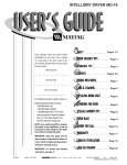
Table of Contents
President’s Letter
0.0 Table of Contents
1.0 Introduction
1.1 Owner’s Record and Details
1.2 Hull Identification Number
1.3 Responsibility of your Dealer
1.4 Responsibility of the Owner
2.0 Commissioning
3.0 Warranty
3.1 Limited Warranty Agreement
4.0 Plan Approval
5.0 Pacific Seacraft 34 Specifications
6.0 General Information
6.1 Labels/Warning on Craft
6.2 Negligence
7.0 Construction
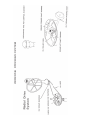
8.0 General Arrangements
8.1 Interior Plan
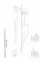
8.2 Profile
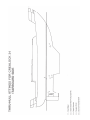
8.3 Lifting Plan
9.0 Propulsion Systems
9.1 Engine/Propellers
9.2 Sails - Weight/Size
9.3 Mast Stepping and Tuning
9.4 Rigging Specifications
10.0 Systems and Circuits
10.1 Fuel
10.2 Exhaust
10.3 Steering
10.4 Thru-Hull Fittings
10.5 Gas
10.6 Electrical
10.7 Bilge
10.8 Plumbing
10.9 Ventilation
11.0 Specific Manuals
1 2 . 0 Hull and Deck Maintenance
12.1 General Care
12.2 Maintenance Below Water Line
12.3 Maintenance Above Water Line
12.4 Deck Hardware
12.5 Sail Maintenance
12.6 Gel Coat Repairs
12.7 Mast Touch Up Repair Procedure
12.8 Interior Maintenance
12.9 Seasonal Decommissioning
12.10 Maintenance Log
13.0 Environmental Considerations
13.1 Pollution Regulations
13.2 Marine Sanitation Devices
13.3 Discharge of Sewage
13.4 Exclusive Great Lakes Use
14.0 Additional Information
14.1 Safety Guiedlines set out by USCG
14.2 Useful Addresses
1
2
7
23
30
31
32
37
42
46
55
90
91
108
109
1.0 Introduction
This manual has been compiled in acccordance with the guidelines set out by ISO (International Standards Organization)
to help you to operate your yacht with safety and pleasure. It contains details of the yacht, the equipment fitted and
supplied, its systems and information on its operation and maintenance. Please read this manual carefully, and
familiarize yourself with the yacht before operation.
It is important that the maintenance schedules listed in this manual are carried out. Insufficient maintenance can
jeopardize one or more warranties accompanying the vessel.
It is Pacific Seacrafts’ policy to continually improve and modify our products. For this reason, you may find that
your Pacific Seacraft has different details or equipment than shown in this manual. In each case, the new details or
equipment have been carefully evaluated to determine that they are consistent with Pacific Seacrafts’ commitment to
excellence.
If this is your first yacht, (or you are changing to a type of yacht you are not familiar with), for your own
protection and safety, please ensure that you obtain both handling and operating experience before “assuming
command” of the yacht. Your dealer, national sailing federation, or yacht club will be pleased to advise you of
local sailing schools or competent instructors.
Pacific Seacraft has made every effort to be accurate, we accept no responsibility for damage arising from
misunderstanding of, or omission from, the contents of this manual. Also, we do not accept or be held liable for any
personal injuries or damage occurring as a result of misuse of, or badly maintained equipment.
Since we are a US boat building manufacturer we will presume US Coast Guard regulations apply to your
situation. International or local authorities may have different laws and codes.
We hope this manual and accompanying accessory manuals will answer any questions which may arise regarding the
operation and maintenance of your vessel. If you need further guidance, do not hesitate to contact your Pacific
Seacraft dealer or Pacific Seacraft directly. (See Useful Addresses). The addresses of all companies refered to in this
owners manual are found in section 14.2, titled “Useful Addresses”. Pacific Seacraft wishes you many happy and safe
nautical miles sailing and we look forward to being of service to you in the future.
PLEASE KEEP THIS OWNERS MANUAL IN A SECURE PLACE ON BOARD YOUR YACHT.
1.1 Owner’s Record & Details
Owner’s Name: ___________________________
Dealer Name: ____________
Address: ________________________________
Salesperson: ______________________________
Address: _________________________________
Telephone No. (Work): ______________________
Telephone No. (Work): ________________________
(Home): _____________________
(Home): _____________________
Boat Name: _______________________________
Delivery
Date: ___________________________
USCG Hull I.D.No.(H.I.N.): _________________
CommissioningYard: _______________________
Registration No: __________________________
Address: _________________________________
(State or Country)
Port of Registry: __________________________
Telephone No: ____________________________
Hull/No: _________________________________
Fax No: _________________________________
Engine Model: ___________________________
Contact Person: ___________________________
Engine Key No:___________________________
In the event of emergency, contact:
Engine Serial No: _________________________
Name:___________________________________
Block Serial No: _________________________
Address: ________________________________
Transmission Serial No: _____________________
________________________________________
Sail
No: _________________________________
Spar No: (at gooseneck) ____________________
Telephone No: ___________________________
Fax No:_______________________________
It is important to fill out the owner’s record in full, and keep it with this owners manual in a secure
and accessible place.
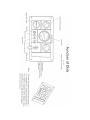
1.2 Hull Identification Number
Your Pacific Seacraft is identified by a hull identification number (HIN) molded into the gel coat at the top starboard corner
of the transom in accordance with US Coast Guard regulations. On canoe stern boats the HIN is located to starboard of the
centerline on the canoe stern body. Please identify your model and hull number when contacting your dealer or Pacific
Seacraft for any reason.
The first three letters of the HIN identify the builder with the code “PCS” The next two numbers identify the model (eg.
34), the next three numbers are the hull number of your yacht (eg. 146), and the letter and last three digits identify the
year manufacture was started and model year.
For Example:
Example PCS34146K989 November 1989, a 1989 model.
Pacific Seacraft Crealock 34 hull #146 started
Builders Code Model Hull No Month & Year Model Year
PCS
34
146
K9
89
Key to Month of Manufacture
Jan -
A
Jul
-
G
Feb -
B
Aug
-
H
Mar -
C
Sep
-
I
Apr -
D
Oct
-
J
May - E
Nov
-
K
Jun -
Dec
-
L
F
It is illegal for anyone (manufacturer, dealer, distributor, or customer) to alter or remove a HIN once it is affixed.
1 . 3 Responsibility
esponsibility of Your Dealer
All Pacific Seacraft yachts are sold through authorized Pacific Seacraft dealers. Dealers have been selected to represent
the company on the basis of their knowledge of yachts and their ability to provide you with the service you deserve.
They are experts in their profession who are committed to provide you with a high level of service and attention.
Your Pacific Seacraft dealer is responsible for the following procedures connected with the purchase and
commissioning of your yacht. Commissioning costs and transportation are normally not included in the price of
your new boat, but are paid by the owner through an arrangement with the dealer. The dealer’s responsibilities
include the following:
•
Preparing a detailed specification list for your yacht, including options, colors and
upholstery selections at time of ordering.
Inspecting the yacht on delivery for loss and damage in transit, and the processing of all claims against the
transport company. Should you notice any additional loss or damage you must notify your dealer within 30
days of arrival, The carrier, the dealer and Pacific Seacraft cannot honor claims for loss or damage in transit
beyond 30 days.
•
Inspecting the packing boxes that come with the yacht to assure that all items are
received in accordance with the Pacific Seacraft packing list.
•
Commissioning the yacht in accordance with the Pacific Seacraft Commissioning
Checklist. The dealer must check and initial each item on the list, and review it
with you.
•
Activating and checking all systems under the conditions of actual usage.
•
Stepping the spars, installing and tuning all rigging.
•
Instructing you on the safe operation of your yacht and all its systems.
•
Familiarizing you with the Pacific Seacraft 24/120 Warranty.
•
Completing the owner’s registration card.
Providing all necessary service under the terms of the Limited Warranty on your yacht, including the
processing of all claims with Pacific Seacraft.
Please contact Pacific Seacraft customer service or sales department if you have any questions regarding the dealer
responsibility.
1.4 Responsibility
esponsibility of the Owner
The following is a partial list of items that are the responsibility of the Owner for the safe operation of your
yacht. However, this must be considered only a partial list of the safety obligations of the owner to be used as a
guideline. Consult your local US Coast Guard office for additional information on the safe operation of your
yacht, (under Useful Addresses).
•
Complete the Warranty Registration form and return it to Pacific Seacraft
promptly.
•
Advise Pacific Seacraft of any change of address, or a change of ownership, to assist
us in maintaining an accurate list of owners for possible future mailings regarding
safety information about your yacht.
•
Confirm that all items outlined in Section 1.3, that are the Responsibility of the
Dealer, are completed by your dealer. If your yacht is delivered to a location other
than the official address or commissioning yard of your Pacific Seacraft dealer, it
becomes your sole responsibility to supervise the commissioning of your yacht, and
to assure that ail the items listed as the Responsibility of the Dealer are completed
by competent professional marine service personnel.
•
Operate your yacht in accordance with instructions provided in all sections of this
Owner’s Manual, the individual supplier instruction manuals provided, and all
applicable US Coast Guard and other regulations.
•
Supervise the maintenance of your yacht by competent marine service personnel in
accordance with all instructions provided in this Owner’s Manual and the individual
supplier instruction manuals.
•
Supply and maintain all safety equipment on board as required by law by the US
Coast Guard and International Offshore Racing Council for your size yacht and the
nature of your voyage, or intended use of your yacht.
•
Under the Safe Boating Regulations, additional equipment might be required by the
US Coast Guard or other local agencies as applicable to your cruising area.
2.0 Commissioning
PACIFIC SEACRAFT DEALER’S COMMISIONING CHECKLIST
BOAT MODEL: ______________________
HULL I.D.#: ______________________
DATE RECEIVED: ______________________
DEALER’S NAME: ______________________
ADDRESS: ______________________
PHONE #: ______________________
FAX#: ______________________
ORIGINAL OWNERS NAME: ______________________
ADDRESS: ______________________
PHONE #: ______________________
FAX#: ______________________
PRE DELIVERY INSPECTION
(Before the yacht is off loaded)
To check the following areas for any type of damage with
reference to the Bill of Laiding * All damaged areas must be photographed.
___________ 1. Hull
___________ 2. Rudder
___________ 3. Propeller
___________ 4. Deck
___________ 5. Deck Hardware
Dealer Int: ______________
Truck Driver Int: ___________
* NOTIFY PACIFIC SEACRAFT 1MMEDIATLY.
Comments
PRE-DEPARTURE CHECKLIST
Initial
#
Desription
Date Comments
1.
File float plan (this can be very informal,
with a dock neighbor, ie. “I’m going out in
the bay for a couple of hours”; or more
formal with the harbor master or yacht
club for longer trips) Let someone know
where your going and how long you expect
to be gone.
2.
Check that necessary thru-hull seacocks are
open. (ie. scruppers,cockpit drains, engine
intake, etc.)
3.
Check batteries for charge and that the
battery selector switch is in the “both”
position.
4.
Check that USCG required safety gear is
aboard and ready.
5.
Verify that levels of fuel and fresh water are
sufficient for your trips.
6.
Verify engine and transmission fluid levels
are at proper levels.
7.
Verify all lights are working.
8.
Prepair running rigging and check for
dragging lines.
9.
Remove sail covers and prepare sails to be
hoisted, (keep sails furled until out of the
slip or mooring.)
10.
Turn dockside power off before
disconnecting from boat. Verify all dockside electrical and or telephone cables are
free from boat and secured.
PRE-DEPARTURE CHECKLIST CONTINUED
Initial
#
Description
Date Comments
11.
Start and warm up engine while secured to dock.
12.
Check water is being pumped thru engine exhaust
13.
After engine is warmed and boat is still
secured to dock, engage transmission while
throttle is at idle to verify linkage is OK,
Do this forward and reverse. Return s
transmission to neutral.
14.
Remove and secure dock lines and safely
depart from dock.
Additional Comments
SEATRIAL
Initial
#
Description
Date Comments
1.
Power with 2 or 3 others out to where
you can maneuver the boat and verify
proper operation under way.
2.
Locate and fit emergency tiller and
become familiar with its operation.
Be sure you can fit it quickly in an
emergency.
3.
Go through all systems on boat and
verify proper operation under way.
4.
Hoist working sails and proceed with
checking sailing charactaristics of the
boat.
5.
Check mast tune and do final
adjustments as necessary, or make
notes and complete when safely ashore.
6.
Pin all turnbuckles when practical,
secure shrouds to spreader tips and
install chafe protection over cotter
pins and spreader tips.
,,
7.
After seatrial and final mast tune,
recheck shaft and coupling alignment.
Realign as necessary.
Additional Comments
PLUMBING
Initial
#
Description
Date Comments
1.
2.
a.
b.
c.
d.
e.
f.
g.
h.
i.
j.
k.
l.
3.
Fill water tanks.
Check plumbing:
Check hoses for kinks
Check hose clamps (do not over tighten)
Bleed pressure water system
Check shower operation
Check head sink & galley sink
Freshwater foot pump
Saltwater foot pump
Bilge pump
Shower sump pump
Ice box drain
Filler hose attachments
Vent hoses
Check head operation
Additional comments
PROPANE SYSTEM
Initial
Description
Date Comment
1.
Check stove operation burners and oven.
2.
Inventory all parts.
3.
Tank holds pressure and securley mounted.
4.
Solenoid functioning correctly.
5.
Check hose connections.
STEERING
1.
Steering cables interface with compass and other instruments.
2.
All fasteners are tight.
3.
Cables aligned, tensioned properly and locked.
4.
Brake engages properly.
5.
Emergency steering system fits and works.
FINAL CLEANING
1.
Interior.
2.
Bilges free from debris.
3.
Exterior.
SAFETY EQUIPMENT ON BOARD
Life jackets
No:
Type:
Throwable floatation devices
Fire extinguishers
No:
Horn
Flares
No:
Fenders with lines
Type:
No:
Docklines
Anchor
Type:
Rode line size and length:
Chain size and length:
If no safety equipment is provided it is the responsibility of the commisioning dealer to supply the necessary equipment for
the seatrial.
UPON ARRIVAL OF BOAT
Dealer Int #
Description/Item
Date Comments
1. Inspect boat on trailer for any visible damage
2. Unwrap & Inspect mast and boom for any
visible damage.
3. Take photographs of any suspected damage.
4. Unload boat from trailer.
5. Wash dirt and road tar from boat to facilitate
visual inspection.
6. Inventory rigging and parts boxes? Advise PSC
IMMEDIATELY of any shortage
7.
Do a thorough visual inspection of boat and
verify optional equipment has been installed
and boat was built according to sales order
(Attachment “A”). Advise PSC IMMEDIATLY
of any discrepancies.
Additional comments
PRIOR TO LAUNCHING
Int
#
Description
Date
Comment
1. Install mast pulpits and bow pulpit if
required.
2. Install lifelines according to lables on
each lifeline
3. Verify that all thru-hull valves are
closed and that the knotmeter tranducer (if ordered) is
installed
4. Visually inspect outside of boat to
verify boat is ready for launching
N
5. Check that propeller is installed and
prop-zinc is secure
6. Check for zinc on bottom gudgeon.
( not applicable on Flickas and Ericsons.)
7. Touch up any bottom paint areas (pads,
bottom of keel, etc.) not previously
painted
8. Check prop nut and cotter key. Mark
shaft for vertical.
9. Install wheel and mark rudder centerline with tape.
10. Install accessoring wire in mast.
11. Install spreaders and Shrouds.
12. Check mast electrical system.
13. Check power strip.
14. Pull Halyard in mast & protect tails
from dirt.
LAUNCHING
Initial
#
Descrition
Date Comments
1.
As soon as the boat is in the water,
check all thru-hulls for leaks and
valve operation. See owners manuel
for operation of thru-hulls.
2.
Tighten all hose clamps related to
both ends of the thru hull hoses.
3.
Move boat without starting engine ^
(tow or by hand) to continue
inspection and commisioning.
Additional Comments
ENGINE SYSTEMS
Intial
#
Descrition
Date
1.
Locate and review engine owners manuel before
proceeding.
2.
Check oil level in engine and transmission.
3.
Check oil discharge notice in place in engine
compartment.
4.
Check coolant level in expansion tank
5.
Check all controls for smooth operation.
6.
Check engine/shaft alignment. Realign if
necessary. (Coupling faces should be within
.002” all the way around edges.)
7.
Open engine cooling intake thru-hulls.
8
Add minimum fuel.
9.
Check thru-hulls exhaust to insure water is being
pumped through cooling system. If not/Turn
engine off Immediatly (refer to engine owners
manuel.) Continueally check
Oil pressure, Temperature readings, and ammeter readings.
10.
Start engine according to instruction in engine
manuel (Attachment “B”). Allow engine to run
for one hour to insure no air is trapped in system.
11
Check packing gland. Gland should be dry with
transmission in neutral and should drip approximatly 6 to 10 drips per
minute when transmission is in gear. Adjust as required. Do not over tighten.
12..
After shutting down engine, Check all belts for correct tension.
13.
Check all engine hoses for leaks or abrasions.
14.
Check hot water system with engine running
(allow 20 minutes for water to heat up.)
ATTACHMENT “B” ENGINE STARTING PROCEDURE
1. Verify that fuel intake valve at the tank is open.
2. Verify that the engine cooling water seacock is open.
3. Turn battery selector switch to “Both” batteries.
4. Verify that the transmission is in neutral.
5. Advance throttle slightlty.
6. Tum the starter switch to the on position.
7. Press the start switch. The engine should start. Adjust throttle position to a fast idle while engine warms up.
ELECTRICAL
Initial
#
Description
Date Comment
1.
Check 12 Volt DC system for proper
operation. Turn battery control
switch to a single battery. Turn off
all breakers at electrical panel. Turn
on all breakers, one at a time, and
check each circuit for proper
operation. Turn control switch to
each battery and repeat this process.
Check battery leads are tight & battery
straps are secure.
2.
Check 110 Volt AC system for
operation. Plug shore power cord
into boat (llOVolt AC). Be sure power
is turned off at the dock before power
cords are plugged into boat to avoid
any electrical shocks. After power
cords are plugged in, turn the power
on at the dock. Check for power at
boat’s llOVolt AC outlets. By plugging
in an applience or tester.
Additional Comments
MAST AND RIGGING
(Further guidance can be found in owners manuel)
Initial
#
Description
1.
Inventory rigging against packing list
attached to the rigging box.
2.
Remove the protective wrap from
the mast and boom.
3.
Inspect for any concealed damage.
Advise PSC IMMEDIATLY of any
discrepancies.
4.
Install halyards and secure to mast.
5.
Install top end of each stay to mast.
Be sure to pin each fitting securely
and tape with rigging tape to
prevent cotter pins from snagging
on sails or halyards.
6.
Run shroud stays over spreader
tips and secure temporarily.
7.
Install turnbuckels on boat and pin
loosely. Make sure tumbuckles are
extended fully for maximum
adjustment to each.
8.
Use crane or hoist to step mast.
Attach lower end of each stay to the
tumbuckles installed earlier. Tighten
only enough to support mast. Do
not tune mast until hoist has been
disconnected, (slide mast boot on to
mast if keel stepped mast.
Date Comments
MAST AND RIGGING CONTINUED
(Further guidance can be found in owners manuel)
Initial
#
Description
Date Comments
9. Install boom on mast. Attach boom lift
10. Install mainsheet blocks and run sheet. Attach topping lift & traveler control lines.
11. Static tune the mast, (Final tuning will be done during sea trials.)
12. Fit mainsail to boom and run reefing lines and other sail controls.
13. Fit headstay, run sheets, if calm wind and safe, hoist and check fit of sail. Repeat for mainsail and any other
sails in boats inventory.
14. Fit roller furling system & check for correct use.
If conditions allow.
Additional Comments
3.0 Warranty
Each Pacific Seacraft yacht is covered by the Limited Warranty detailed in the following pages. Your yacht was carefully
inspected at numerous stages of construction by our skilled Quality Engineering experts, but occasionally a situation may
occur that requires attention under this Limited Warranty. Before proceeding with any warranty related work, you should
carefully read the enclosed copy of your warranty and the guidelines listed below:
•
Complete the enclosed Warranty Registration form within 15 days of delivery of
your yacht to validate your warranty.
•
Should warranty related work be required on your yacht, first contact your Pacific
Seacraft dealer. He is a knowledgeable professional who is familiar with your boat,
and knows the most efficient way to complete the necessary work. Your Pacific
Seacraft dealer will contact Pacific Seacraft for authorization to proceed with the
work, and for detailed instructions to correct the situation in the most expeditious
and satisfactory manner.
•
If it is not reasonably possible to return your yacht to your own Pacific Seacraft dealer for warranty work, then make
every effort to take your yacht to another authorized Pacific Seacraft dealer or service yard. If this is not possible,
contact the Pacific Seacraft Customer Service Department to request authorization to have the work performed at
another location.
•
Authorization must be granted by Pacific Seacraft before any work is carried out for this warranty to be valid. This
applies to both authorized and non authorized yards.
•
Any claim for payment under this Limited Warranty must be fully documented, with details of all materials and labor
used including quantities, hours and rates. Pacific Seacraft agrees to make full payment for work covered by this Limited
Warranty on the basis of reasonable hours for the work actually performed and at prevailing rates in the area for
materials and labor.
Pacific Seacraft
Corporation
24/120 LIMITED WARRANTY AGREEMENT
EFFECTIVE JUNE 1, 1997
Pacific Seacraft Corporation
1301 East Orangethorpe Avenue
Fullerton, CA 92831 (714) 879-1610 or FAX (714) 879-5454
Pacific Seacraft Corporation
24/120 Limited Warranty Agreement
Pacific Seacraft Corporation (“Builder”) offers to the
original purchaser (herein after referred to as “Purchaser”) the following warranty program designed to help protect your
investment.
Builder expressly warrants to the first purchaser (“Purchaser”) that any new sailboat or power boat (“vessel”) it manufactures
and sells is to be free from defects in workmanship and materials (except as hereinafter provided) for a period of twentyfour (24) months under normal use for which it was intended, provided it has been properly operated. No implied warranty
of merchantability or fitness for a particular purpose shall apply except during the twenty-four (24) month period of this
limited warranty. SOME STATES DO NOT ALLOW LIMITATIONS ON HOW LONG AN IMPLIED WARRANTY LASTS,
THEREFORE THE AB OVE LIMITATIONS MAY NOT APPLY TO YOU.
1. Express Warranty.
Builder warrants to the Purchaser that it will repair or replace any part manufactured by it which is proven to Builder’s satisfaction
to be defective by reason of faulty workmanship or material for a period of twenty-four (24) months. Builder will also, within the
same period, reimburse the Purchaser for the labor costs involved in the removal of the defective part and the reinstallation of
the repaired or replaced part, provided that the labor cost will be based on an amount agreed to by Builder. The twenty-four (24)
month warranty period will commence from the date of the sale to the Purchaser. Parts furnished by Builder but not manufactured
by Builder, will carry only the warranty of the manufacturer and are not included in Builder’s warranty. Transportation charges
and duties for the return and replacement of parts shall be borne by the Purchaser. Purchaser waives all time requirements
for the return of the defective parts being considered in accordance with this express warranty. This warranty shall apply to
consumer sales only and is not transferable to any other purchaser other than the Purchaser. This warranty shall not apply to
vessels that are used for charter service, for commercial use, or for any illegal activity.
2. Blister Warranty.
Builder will reimburse the Purchaser the direct repair
costs to repair any gclcoat damage below the water-line caused by osmotic blisters for a period often (10) years according to
the following schedule: Yearsone through three (1-3) will be reimbursed at one-hundred percent (100%). Years four through
ten (4-10) the reimbursement will be prorated at 12.5% per year for the remaining seven (7) years. No repairs will be paid for
after ten (10) years. This warranty is only binding if no submerged surface has been abraided, gouged, or otherwise invaded to
the extent that it reduces the thickness of the vinylester “skin coat” first laminate of the hull skin. It is the responsibility of the
Purchaser to maintain the integrity of this layer to the original factory specifications over the warranty period, otherwise this
blister warranty will become void. This blister warranty does not extend to the condition, effectiveness, or durability of any
topically applied coatings such as anti-fouling bottom paint or epoxy coatings. Gelcoat damage is not covered by this warranty
if it has been subjected to impact, sanding, sandblasting or other types of abrasives including chemical etchants either applied
or environmental. Costs associated with hauling, washing, blocking, painting and storage are considered as incidental and are
not covered by this warranty.
3. Notice.
Purchaser must notify Pacific Seacraft Corporation at 1301 East Orangethorpe Avenue, Fullerton. California 92831, or it’s
selling Distributor by certified mail, return receipt requested, of a breach of warranty within thirty (30) days after the discovery
thereof, but no later than the end of the warranty period, otherwise such claims shall be deemed waived. No allowance will be
granted for any repairs or alterations made by Purchaser without Builder’s prior written consent. The Purchaser is required to
provide written notice to Builder and allow Builder the opportunity to cure any breach before commencing a civil action.
4. Compliance of Safety Code.
Due to the worldwide distribution of Pacific Seacraft vessels, Builder cannot and does not warrant its vessels and parts to
meet the requirements of specific safety codes of any state, municipality or other jurisdictions. Purchaser is advised to
consult with government regulatory agencies in respect to
Effective date 6/1/97
Purchaser’s risk and liability resulting from use thereof.
5. Alteration an/or Addition.
This warranty shall not apply to any installed additions or painted coatings applied to the vessel outside of Builder’s manufacturing
facility, or shall not apply to any Pacific Seacraft vessel, or parts thereof, which have been repaired or altered outside of Pacific
Seacraft’s plant or have been subjected to misuse, negligence or accident, or have not been operated in accordance with Pacific
Seacraft’s or manufacturer’s printed instructions.
6. Disclaimer.
Pacific Seacraft’s written warranty is exclusive and in lieu of all other warranties, whether oral or written, express or implied.
7. Special Damages.
PACIFIC SEACRAFT IS NOT RESPONSIBLE FOR ANY INCIDENTAL, SPECIAL OR CONSEQUENTIAL DAMAGES
RESULTING FROM AN Y BREACH OF THIS WRITTEN WARRANTY. Builder shall not be liable for any loss or damage
resulting, directly or indirectly, from the use or loss of use of the vessel. Without limiting the generality of the foregoing this
exclusion from liability embraces the damages for which the Purchaser may be liable to another person, damages to property,
injury to or death to any persons, loss of use, loss of time, loss of income, storage costs, inconvenience or commercial loss.
Builder’s liability, if any, for the vessel furnished under this warranty shall in no event exceed the cost of correcting defects in
the vessel as herein provided and upon the expiration of this warranty any such liability shall terminate.
8. Agent and Representative.
Builder neither assumes nor authorizes any person to assume for it any liability in connection with the sale or use of the Pacific
Seacraft vessel thereof, and there are no oral and written agreements or warranties collateral to or affecting this agreement.
9. Paints, Finishes and Maintenance.
The warranty hereinabove set forth shall not be deemed to cover any paints, varnishes, gelcoats (except as noted in 2. Blister
Warranty) or chromium
plated finishings, furnishings, or metal because they
are affected by climatic, environmental and use conditions beyond the control of the Builder. It is the Purchaser’s responsibility
to provide an adequate maintenance program to protect the fabric of the boat.
10. Product Improvement.
Builder reserves the right to revise, change or modify the design or construction of its vessels and any part thereof without being
obligated to incorporate said revisions, changes or modifications in vessels manufactured prior to the date of said revisions,
changes and modifications.
11. Representation and Affirmation.
Any description of the goods contained in the sales materials is for the sole purpose of identifying them, it is not part of the
basis of the bargain, and does not constitute a warranty that the goods will conform to that description. The use of any sample
or model is for illustrative purposes only, it is not part of the basis of the bargain, and it is not to be construed as a warranty
that the goods will conform to the sample or model. No affirmation of fact or promise made by Builder, whether or not in the
sales contract, will constitute a warranty that the vessel will conform to the affirmation or promise, except that Builder does
expressly warrant that the new vessel sold under the sales contract is to be free from defect in workmanship and materials for
twenty-four (24) months under normal use for which it was intended, provided it has been properly operated.
12. Time to Bring Action.
This warranty shall be governed by the laws of the State of California. Any action for breach of any warranty must be
commenced within one (1) year after the cause of action has occurred and shall be brought in a state or federal court of
competent jurisdiction located in the County of Orange, California.
13. Warranty Registration Certificate.
It is the Purchaser’s responsibility to complete the warranty registration certificate and return it to the Builder within ten (10)
days after the sale of the boat. The certificate establishes the date of purchase by the Purchaser for the warranty service period
to take effect.
Pacific Seacraft
Corporation
Limited Warranty Registration Certificate
Name of Owner ______________________________________________________
Street Address _______________________________________________________________
City/State/Zip ______________________________________________________________
Home Phone ______________________
Office Phone ______________________
USCG Hull ID Number _________________________________
Engine Serial Number __________________________________
Transmission Serial Number ______________________________
Date of Sale _____________________________
Selling Distributor __________________________________________________________
Boat Name____________________________________________
I hereby acknowledge receipt of the Pacific Seacraft Corporation 24/120 Limited Warranty Agreement and I agree
to abide by the terms, provisions, conditions and limitations contained herein.
=.
Signature of Owner ____________________________________ Dated _____________________
Copy 1 to be retained by the owner
Copy 2 to be returned to Pacific Seacraft Corporation
4.0
PLAN APPROVAL
Pacific Seacraft has submitted their constructional blueprints to the American Bureau of Shipping for their approval
in accordance with the requirements of the Guide for Building and Classing Offshore Racing Yachts (1986)
which were set out by the American Bureau of Shipping. The plans were approved on 26th March 1992.
The plans submitted were:
Construction Section and Laminate Schedules
Construction Plan Profile
Rudder Construction
Gudgeon Casting
Steering System Installation
Joiner Section
Deck Core Arrangement
Thru-hull Installation
Further plans were submitted and although the American Bureau Of Shipping had no specific requirments covering
the submitted plans, they were reviewed and approved.
Further plans submitted were:
Chainplates
Forestay Fitting
AMERICAN BUREAU OF SHIPPING
ABS PID NO.
YACHT:
BUILDER:
ADDRESS:
BUILDER’S STATEMENT
DATE:
THIS IS TO CERTIFY THAT THE UNDERSIGNED IS DULY AUTHORIZED TO DECLARE ON
BEHALF OF THE BUILDER OF THE ABOVE NAMED YACHT, AND;
THAT THE BUILDER DURING CONSTRUCTION HAS HAD ACCESS TO THE FOLLOWING
ABS APPROVED AND AMENDED PLANS AND DOCUMENTS:
PLANTITLE
PLAN NUMBERS
1.
2.
3.
4.
5.
6.
7.
8.
9.
10.
THAT IT IS VERIFIED THAT THE YACHT HAS BEEN CONSTRUCTED BY THE BUILDER,
STRICTLY IN ACCORDANCE WITH THESE ABOVE LISTED PLANS AND DOCUMENTS,
AMENDED, WHERE APPLICABLE.
DATE:
SIGNED; TTILE:
4.0 Plan Approval
AMERICAN BUREAU OF SHIPPING
CERTIFICATE OF HULL SCANTLING PLAN APPROVAL
This is to CERTIFY that the design scantlings of the hull structure of:
YACHT NAME:
(3)
SAIL NO.:
(2)
OWNER:
(3)
ABS REVIEW NO.
(4)
DESIGNER:
(5)
DESIGN NO.
(6)
BUILDER:
(7)
HULL NO.
(8)
as shown on the ABS approved plans and documents, have been reviewed and found to be in compliance
with ABS Guide for Building and Classing Offshore Racing Yachts, and that ABS has received the
Builders’ or ABS Surveyors’ statements that this boat was built in accordance with the ABS approved
plans.
ABS CERTIFICATE NO.:
(9)
G. M. Ashe (10)
Director of Engineering By Direction
Group Head/Date
ABS OFFICE:
(11)
Items (1), (2), (3), (5), (6), (7), and (8) are to be completed by designer then submitted to ABS for
completion, after approval of plans and receipt of Builder’s Statement.
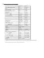
5.0 Pacific Seacraft 34 Specifications
Imperial
Metric
LOA (including Bow Sprit)
34’ 1”
10.39m
LWL
26’ 2.5”
8.00m
Beam Maximum
10’
3.00m
Mast Height Above Water*
44’ 3”
13.48m
Head Room
6’ 3”
1.90m
Sail Area - Sloop
534 sq. ft.
49.60m2
- Cutter
649 sq. ft.
60.29m2
Sail Measurements
I=40.33’
12.29m
P=34.40’
10.49m
J=14.50’
4.42m
E=14.00’
4.27m
Displacement
13,200 lbs.
5,987 kg
Lead Ballast
4,800 lbs.
2,177 kg
Draft - Standard Keel
4’ 11”
1.50m
- Shoal Keel
4’ 1”
1.24m
Wetted Surface Area (for antifouling) 300 sq. ft.
27.88m2
Engine
Yanmar Diesel
Horsepower
38hp
Voltage
12 VDC
110VAC
Batteries
(2) Deep Cycle Marine 86Ah
Tank Capacities (Approximate)
Fuel - Standard
32 gal.
121.12 liters
- Shoal
27 gal.
102.20 liters
Fresh Water - Bow
36 gal.
136.26 liters
- Stern
39 gal.
147.62 liters
Holding
16 gal.
72.73 liters
Designer
W.I.B. Crealock
* Measured from the waterline to the top of the mast, it does not take into account other appendages
Note: All specifications are subject to change without notice.
6.0 General Information
6.1 Labels/Warning
els/Warning on Craft
The following labels and warnings are located on the relevant parts of your boat. They are there as reminders for the
safe operation of your boat. Each crew member should know the relevance of each label.
Location of Labels
1. Cockpit locker near battery charger
2. Reverse side of the electric panel
3. Propane locker
4. Near intake valve in the head compartment
5. On the swim ladder
6. Near the water heater (PSC 34 only)
7. Cockpit engine hatch and engine cabin cover.
8. In locker near manual bilge pump
1.
2.
3.
4.
5.
6.
7.
8.
9.
6.2 Negligence
LAW ENFORCEMENT
This section is intended only as an overview of some key laws and is by no means complete or comprehensive.
It is your responsibility to familiarize yourself with local laws.
A vessel underway, when hailed by a Coast Guard vessel is required to heave to, or maneuver in such a manner
that permits a boarding officer to come aboard.
Other Federal, State and local law enforcement officials may board and examine your
vessel, whether it is numbered, unnumbered or documented.
The Coast Guard may impose a civil penalty of up to $1,000 for failure to:
• comply with numbering requirements;
• comply with equipment requirements;
• report a boating accident (see Safety Section); or
• comply with other federal regulations.
Failure to comply with the unified Inland Rules of the Road (Inland Navigation Rules Act of 1980) can result in
a civil penalty of up to $5,000. It is compulsory to have this book on board if the vessel is over 12 meters or
39 feet. However, you are advised to have this book as part of the boats’ library. This is obtainable from:
The Superintendent of Documents
US Government Printing Office
Washington, DC 20402
Tel: (202) 783-3238
Stock Number: 050-012-002053
“Inland Rules of the Road”
Improper use of a radiotelephone is a criminal offense. The use of obscene, indecent or profane language during
radio communications is punishable by a $10,000 fine, imprisonment for two years or both. Other penalties exist
for misuse of a radio, such as improper use of Channel 16 VHF-FM.
Channel 16 is a calling and distress channel. It is not to be used for conversation or radio checks. Such
traffic should be conducted on an authorized working channel.
OPERATING A VESSEL WHILE INTOXICATED became a specific federal offense effective January 13,
1988. The final rule sets standards for determining when an individual is intoxicated. The BAC (Blood Alcohol
Content) is .10% (.08% in Utah) for operators of recreational vessels being used only for pleasure. Violators are
subject to civil penalty not exceeding $1,000 or criminal penalty not to exceed $5,000, 1 year imprisonment, or
both.
NEGLIGENT OPERATION of a vessel which endangers lives and property is prohibited by law. The Coast
Guard may impose a civil penalty for negligent operation. GROSSLY NEGLIGENT OPERATION is a criminal
offense and an operator may be fined up to $5,000, imprisoned for one year, or both. Some examples of actions that
may constitute negligent or grossly negligent operation are:
• Operating a boat in a swimming area.
• Operating a boat while under the influence of alcohol or drugs.
• Excessive speed in the vicinity of other boats or in dangerous waters.
For further information, consult the “United States Coast Guard Information Pack”.
7.0 CONSTRUCTION
A successful ocean voyaging yacht must gracefully blend structural integrity, comfort and performance. Pacific
Seacraft has these attributes in abundance, unique in the world of series production boat building.
The designer and builder alike have worked closely together as a team to develop and manufacture a yacht which has
the ability of transversing oceans the world over.
There are a number of unique features within the construction of a Pacific Seacraft yacht which are consistant with
its quality.
Some of these features are highlighted as follows:
LAMINATES
Structural laminations in all Pacific Seacraft yachts are carefully hand cut and layed up entirely by hand. Each area
is squeeged to remove all excess resin and air pockets keeping the weight down and most efficently producing the
proper glass to resin ratio for maximum strength.
HULL
The hull is laid up in a one piece mold. The outer skin starts with the gel coat color being applied by a mechanical
spray system. For superior blister resistance the gel coat is backed up by a layer of mat laminated in
vinylester resin. The vinylester resin is evenly distributed to achieve a very resin rich mix for excellent
fillament saturation and then squeeged. This proven outer skin application is crucial to the prevention of
osnotic blisters. The hull is constructed of alternate plies of mat and roving, the roving giving directional strength
fore and aft, and athwartship, and the mat giving strength through thickness. The polyester resin ties this
reinforcement matrix together into a solid and rigid laminate. Additional laminates in specific areas eg.
chainplate attachments, keel and hull centerline are applied to further reinforce and enhance rigidity and
strength in high load areas.
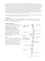
KEEL
The keel is a one piece solid lead casting, poured in a ceramic mold to close tolerances. Stainless steel bolts are
cast into the lead. These bolts extend through the hull, and are secured by stainless steel nuts and backing plates. A
customised template for each
hull ensures an accurate fit.
The joint between the keel
and the hull is filled with
epoxy to ensure a waterproof
and precise joint. The bolts,
backing plates and nuts are
bedded in the same epoxy
compound within the keel stub.
The patented Scheel keel
design allows performance
and stability comparable to
the standard keels but with
significantly less draft. What
is gained is the ability to sail
into waters which are off
limits to deeper draft boats,
thus providing greater range
of cruising grounds
RUDDER & SKEG
The rudder and skeg construction is one of the most critical (and overlooked) yet vu nerable parts of a cruising
yacht. The rudder is constructed to be self-supporting, it is further supported by the skeg which is reinforced with
a molded-in structural steel plate. The skeg and rudder are connected at the lower end by a massive manganese
bronze gudgeon.
HULL LINER
After the hull is released from the mold the interior hull liner is installed. Pacific Seacraft has been one of
the leaders within the industry for pioneering this type of construction technology. A unitized hull liner gives
the hull a tremendous amount of support and structural rigidity to resist the torsion moments imposed by the
natural workings of the yacht in a seaway.
Semi circular plywood bulkhead ribs are bonded into the vertical underbody plane of the liner, so that it has
maximum structural transverse and longitudinal support attachment to the hull. Being of a predominantly
sandwich construction, for superior strength, it is liberally bonded to the hull skin with fiberglass mat and roving
tape. This glass to glass bond is far superior than glass to plywood counterparts. All areas of the bilges including
the hull, floor timber, cabin sole, etc. are all glass and therefore resistant to rot and are maintenance free.
The hull liner also incorporats integrally designed features such as the engine beds, water and holding tanks,
points of attachment for mechanical systems, shower pan and cold storage compartments. The ice box insulation
is pre-formed prior to liner being installed into the hull giving superior insulation properties. All storage
compartments incorporated by the hull liner are fully self contained to prevent articles from becoming lost. The
hull liner affords a surface which is easy to keep clean especially at foot level.
The interior of all storage compartments are gel coated to seal moisture out of the laminate from within the
boat. This will help the owner to keep bilges and storage lockers clean.
BULKHEADS
Ail bulkheads are tightly hand fitted to the hull and bonded with fiberglass mat and woven rovings. Where
applicable the bulkheads are thru-bolted to the deck beams to ensure a solid structural support of uncomprimise
stiffness. Cornered edges and trim are sold teak.
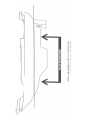
HULL TO DECK JOINT
The vital hull to deck joint is engineered
with an overlapping double flange bedded
high tensile polyurethane adhesive compound
and through fastened with stainless
steel machine screws. This is finally
capped with a teak caprail which is also
thru fastened. The resulting bulwark ‘box’
section formed, dramatically affords superior
structural rig dity in this often overlooked
area. This type of join, while expensive
and difficult to achieve, is one of the most
watertight connections available in current
production technology.
DECK
The deck is laid up in a similar way to the hull in
a one piece mold which incorporates a moldednon-skid pattern. Using the same glass fiber
reinforcement, it incorporates a balsa core for
additional stiffness and insulation.
Plywood
used in areas of pa-ticularly high compressive
stress such as the winch mounts and cockpit sole.
in
in
is
DECK FITTINGS
All deck fittings are thru-bolted onto backing plates and liberally sealed with a plyable poyurathane sealent to prevent
leakage. The backing plate on the underside of the deck provides a firm foundation to withstand the loading that may
be exerted on the fitting. Lifeline stanchions are thru-bo!ted with backing plates to the vertical bulwarks to
prevent water from seeping through the bolt holes. Backing plates help spread the load over a greater surface area
and also make it easier to remove hardware for maintenance. Chainplates are thru-bolted to the hull providing the
widest possible base for mast support and directing the loads straight to the hull. The companionway has been
designed in conjunction with the seahood to eliminate the effects of driving rain and spray from entering the cabin
by a series of baffles and scuppers integrally molded in the deck. The companionway is strengthened and protected
from flooding by having a high bulwark which divides the cockpit from the cabin. A large engine hatch located in the
cockpit sole provides additional access to engine, transmission and stuffing box. The removable hatch has easy grip
lifting handles and is secured with four bronze knurled knobs onto a solid neoprene gasket to ensure a water tight seal.
CANOE STERN
Some of the yachts in the Pacific Seacraft range have the famous canoe stern. There is no magic shape of a stern though
the stern is more important than the bow in determining motion. One should always look at a stern as a potential
bow, since the natural tendency of a boat is to present its rump to the seas if left to its own devices. The very
attractive look of the canoe stren enhances the lines of the yacht.
JOINERY WORK
Pacific Seacraft operates its own woodworking mill and performs all joinery work on-site. This gives the
company a high degree of control over these operations which are ultimately reflected in the workmanship and
quality.
SEA VALVES OR SEACOCKS
All sea valves used below the waterline have an Underwriter’s Laboratory approval rating. The seacock
is not only screwed to the stem of the thru hull fitting but it is additionally triple-thru bolted to the hull. To
prevent leakage, the sea valve is mounted on a resin dipped plywood compression washer and sealed against the
inside hull surface.
FUEL TANKS
Fuel tanks are all aluminium and positioned within the keel well giving superior balance properties. An inspection
plate affords clear access for easy draining and cleaning. The tanks have been designed so that they can be easily
removed from the boat through the companionway hatch, should repair become necessary.
MECHANICAL AND ELECTRICAL SYSTEMS
All mechanical systems are installed in a specially devoted work area prior to the placement of the yacht’s
joinery. This allows easy positioning of the systems which ult mately leads to clear and free access for the
owner. Hose and wire runs are adequately supported, color coded and marked for easy identification.
Copper electrical wiring used throughout the boat is marine rated, vinyl covered and tinned. Piping as applicable
in the fuel system is in accordance with the USCG approval rating. Where wire harnesses and hosing pass through a
bulkhead adequate protection affDrded by a rubber grommet prevents chaffing from vibration.
PLUMBING
The freshwater system is fed from two (Crealock 44 is fitted with three) built in water tanks. These run through
separate electrical water pumps in the head(s) and galley to provide water pressure. Fresh water heaters are standard
on all Pacific Seacraft yachts. Foot pumps are installed in the head(s) and gallay to conserve water and electricity.
The head shower pan has a drain that can discharge grey water overboard via an electric sump pump. Ail head and
galley sinks drain grey water overboard. The head plumbing allows discharge of black water into the holding
tank or, when applicable, directly overboard.
HARDWARE
Pacific Seacraft endevours to select the most reliable hardware available. In addition to function, design and
maintenance, sevice and repair are factored into the installation of the equipment. Years of boats sailing around
the world have determined the most appropriate hardware selection.
Pacific Seacraft continually strives to seek perfection and excellence in the constructional attributes of the
boats. The company is always seeking different approaches in improving the product. Many improvements have
originated from owners like yourself and we welcome your suggestions and ideas.
8.0 General Arrangements
8.1 Sail Plan
8.2 Side Profiles & Deck Layout
9.0 PROPULSION SYSTEMS
9.1 ENGINE
Pacific Seacraft has considered a number of factors in choosing the most suitable diesel engine for each boat we
manufacture.
1. The performance and reliability of the engine
2. The ease of spare parts availability
3. Reliable service center network
4. Immediate warranty action
5. Accessibility of changeable parts, eg. filter, oil, etc.
The Pacific Seacraft 34 is fitted with a Yanmar 3JH2E 4-stroke; three cylinder 38 h.p. diesel engine. It
incorporates a fully enclosed freshwater cooling system with a heat exchanger. The transmission is a
constant mesh gear with a multiple disc clutch and has a ratio of 2.14 to 1.
The Yanmar manual which accompanies this owners manual gives an in-depth look at all aspects of care and
maintenance of your engine. The Yanmar manual is easy to follow and we strongly advise you to read it carefully as
it provides an in-depth understanding of the engine and has a troubleshooting guide.
Once you have read the Yanmar manual, the following is a general guide which will act as a quick reference. If you
have any questions please phone your Yanmar dealer/service center for assistance. (See operators manual for
addresses and phone numbers -servicing agents).
BEFORE STARTING A NEW ENGINE
•
•
•
•
•
•
•
Locate the cooling system and fuel system and note the location of shut off valves. Turn both valves to
open position. (Refer to the schematic diagram in the Thru Hull section 10.4).
Shift gear to neutral position.
Check engine fluid levels. Freshwater coolant system may need to be purged of air. (If required refer to
engine bleeding instructions in this section).
Check that electrical terminals are secure, particularly at starter motor and battery.
Check for loose or missing bolts and nuts in engine pan.
Check for loose or disconnected piping and hoses, raw water uptake, exhaust discharge, and fuel
hoses.
Check belt tensions - refer to the Yanmar manual.
STARTING OPERATIONS.
• Open the engine sea water cooling intake valve, {see thru hull diagram section 10.4)
• Check raw water strainer for unobstructed flow.
• Check that there are no tools or other articles near rotating parts of the engine.
Turn on the battery switch to engine start position “1”.
• Set the gear shift to neutral position.
• Set the fuel lever/throttle to half speed.
• Check surrounding waters for swimmers, boaters and floating debris.
• Turn engine key to the “ON” position. The alarm buzzer will sound and the red warning lights will come
on.
• Push the “START” button.
• When engine has started, the alarm lights and buzzer will go off. The buzzer will sound and the relevant
light will come on if:
– There is low oil pressure.
– Coolant water temperature is too high.
– Battery is not charging.
NOTE: IF THE LIGHTS OR BUZZER STAY ON IMMEDIATELY STOP THE ENGINE AND
TURN KEY TO OFF, THEN TROUBLESHOOT.
AREAS TO CHECK AFTER ENGINE IS STARTED
• All alarm buzzers and lights are off.
• Cooling water is being discharged from exhaust outlet.
• No leakage from oil, water, fuel or exhaust systems. Check in engine compartment and bilges.
• Warm up the engine for 5 minutes with no load (neutral) to allow oil to spread all the way to the main
bearings and other moving parts. {For breaking-in, idle the engine at low speed for 15-20 minutes).
If the warm up operation is normal, engage the gear and begin operation.
Do not run the engine above 2500 RPM for the first 50 hours of operation.
Always set the battery switch and main switch to “ON” position during operation. The diodes of the alternator
will be damaged if the switch is turned to the “OFF” position during engine operation. Turning the switch between
“1”, “ALL” and “2” will not damage alternator diodes. We advise Battery 1 be used as the engine starting battery
and Battery 2 the “house” battery.
TO STOP THE ENGINE
•
•
•
•
•
•
•
Place in neutral.
Always run engine at idle for about 5 minutes before shutting down.
Failure to do so will result in a rapid fall of engine temperature and may damage the engine
gaskets.
Pull “Stop” cable until the engine shuts down. Alarms and lights will turn on.
Turn engine key to off. Alarms and lights will turn off.
Turn engine battery switch to the “OFF” position, if leaving the boat.
The automatic bilge is wired directly to the bilge.
ROUTINE MAINTENANCE
For the engine to have long-term high performance and reliability here are a few suggestions for you
to follow. If you feel unable to carry out any of these recommendations, then contact your Yanmar service
center. The Yanmar engine manual explains the following in more detail:
•
•
•
•
•
•
•
•
•
•
•
•
Use recommended lubrication oil and change oil regularly. Since engine oil is mixed with air and exposed
to high temperatures, it will oxidize and its properties will gradually change. It is extremely important to the
performance of your engine that the lubrication oil and oil filter are changed at the following intervals:
– After the first 20 hours of operation.
– After the second 30 hours of operation.
– Every 100 hours thereafter.
Check transmission oil level each time before the boat is used.
Always top off the fuel tank whenever possible, to prevent water condensation inside the tank, particularly if
the boat is to be unused for a period of time. Do not rely on the water separator. (For further information see
Fuel Systems).
Check Racor water separator regularly and drain as necessary. (Filter should be replaced at least once a year).
Check the fuel valve on the tank and the secondary fuel filter (engine). The fuel valve may be used to shut off
the fuel supply, in the event of a fuel line rupture.
Check the operation of the fuel pump by listening for a discernable “clicking” sound as the fuel is being
pumped to the engine. If there is no clicking check its fuse.
Check the engine mountings, particularly the studs and rubber blocks.
Check the coupling bolts on the shaft.
Check the stuffing box clamps and adjust shaft packing gland nut as necessary to
achieve a drop rate of at least six drips per minute.
The boat hull will assume its own shape when it is launched and operated in the water. It is therefore
important to check the engine alignment once a year or each time the boat is dry stored. Do not operate the
engine if you believe the shaft alignment is incorrect as this will cause excessive wear on the cutlass bearing.
Contact your Pacific Seacraft dealer if an out of alignment condition exists.
Check throttle shift, stop cable, and every connection. Oil the control handle shaft
bearings with #30 motor oil. Use a good grade of Teflon spray with an extended
nozzle for the pedestal end of the engine control push/pull cables. At the engine,
clean off the control cable metal ends and spray with Teflon grease. This will
increase cable life and make operation easier. Engine cables are subjected to high
heat from the transmission, and salty bilge water, both very hard on moving parts.
If any cable becomes stiff, replace.
Note: Lubricate all connecting pivot pins.
Every 250 hours of operation, disassemble the air intake and remove the element, inspect and clean with
detergent.
NOTE: ENGINE WARRANTY WILL BE INVALID IF MANUAL PERIODIC CHECKS AND
MAINTENANCE RECOMMENDATIONS ARE NOT FOLLOWED.
COMMON CAUSES OF ENGINE MALFUNCTION
•
•
•
Engine Overheating
If the engine temperature gauge starts to rise over the critical mark, you must immediately stop the engine.
Check the fresh water radiator level, once the engine temperature has cooled using extreme caution. Refill as
necessary. Determine where the leakage occurred. If the radiator water level appears normal, restart the
engine and check the exhaust for normal amounts of discharge water. If not enough water is being discharged,
either:
– the seawater intake valve is closed;
– the seawater intake strainer is clogged;
– the seawater circulating pump is faulty; or
– an air blockage has occurred in the fresh water engine system. (See instruction sheet).
– If none of the above consult a Yanmar dealer or service center.
Low Oil Level
If the engine oil level alarm sounds, stop the engine immediately and check the oil level. Add oil as necessary
and check for leaks. Abnormal consumption of oil could indicate a serious mechanical problem which should be
attended to immediately.
Fuel Starvations
– Fuel pump not functioning.
– Air leak into fuel pick up line.
– Fuel tank empty.
– Dirty or plugged fuel filters.
ENGINE BLEEDING INSTRUCTIONS
•
•
•
•
•
•
•
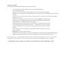
Follow the diagram (Typical Fuel System).
Locate HEX head bolts with “phillips” screw slots in head of bolt - one located on top
of fuel filter housing and one located on fuel injection pump.
Loosen the “phillips” head bolt on fuel filter housing two turns.
Operate the manual handle on the engine mounted mechanical fuel “feed” pump until
a solid stream of fuel flows from the “phillips” head bolt. Tighten bolt.
While still operating the manual pump, loosen “phillips” head bolt two turns located
on fuel injection pump until a solid stream of fuel flows from the “phillips” bolt.
Tighten bolt.
Using a 17mm wrench loosen nut on each fuel injection line at the fuel injection
nozzle. Do this one at a time until a solid stream of fuel flows from each nut.
Tighten each nut.
Fuel system should now be free of air.
For further troubleshooting, consult your Yanmar engine service manual which accompanies this manual.
Propeller and Shaft Specifications
Boat Model
Flicka
Dana 24
Pacific Seacraft 31
Pacific Seacraft 34
Pacific Seacraft 37
Pacific Seacraft 44
2-Blade
12” x 11”
15” x 12”
16” x 12”
17” x 12”
18” x 14”
21” x 13”
Note: Pkg flax size 3/16”
Cutlass Bearings are 1” x 1-3/8” x 4”
3-Blade
12” x 9”
14” x 10”
15” x 10”
17” x 10”
18” x 12”
20” x 12”
Shaft Length/Diameter
36” x 1”
27” x 1”
66” x 1”
36” x 1”
44-1/2” x 1”
Aqua-Drive Jack Shaft
(1-1/2” x )
9.2 Sail Weight/Size - Pacific Seacraft 34
Main with 2 Rows Reef Points
Fully Battened Mainsail
Working Jib (85%)
Yankee
100% Jib w/ Reef
120% Genoa
130% Radial Roller Furling Genoa
140% Genoa
140% Reachor/Drifter
Staysail w/ Reef Points
Storm Jib
Storm Trysail
Cruising Spinnaker
Oz.
7.1
7.1
7.1
7.1
7.1
6.3
4.1
5.6
3.6
7.1
7.9
7.9
1.5
Sq. Ft.
241
241
177
211
322
350
379
409
409
115
59
66
895
9.3 MAST STEPPING AND TUNING
DOCKSIDE STEPPING AND TUNING OPERATION
Stepping and rigging the mast are part of the commissioning procedure. This guideline is included to give you a
basic understanding of what is involved. Your local boatyard and/or dealer should have trained professionals to
carry out this procedure. It is important for the owner to understand and be able to perform this operation.
PREPARATION BEFORE LIFTING
Before the mast is stepped it is important to check all electrical fittings (lights, antennae, cables, etc.) for
proper operation, also check the operation of halyards and clean all blocks with fresh water. It is easier to carry
out adjustments with the mast in a horizontal position, rather than swinging about in a boatswain chair with the
mast in the vertical . Check that all connections are tight and sealed with tape. Make sure the shrouds are free so
they are not caught by the lifting gear when they need to be secured. Be careful not to scratch the mast during this
operation.
LIFTING
Using a yard crane step the mast butt on the mast step and position vertically
Once the mast is stepped, secure the shrouds until the slack has been taken out of them.
TUNING IN COLUM
The first step is to set the mast straight on the athwartships axis. Using the main halyard as a plumb line
measurer, adjust the upper shrouds to get the mast directly over the center line. Check this by taking the halyard
out to each rail, and if the mast is plumbed the halyard will reach the same point on the rail on each side.
HEADSTAY / BACKSTAY
Tighten the headstay turnbuckle until the mast is vertical and then tension the backstay until it is firm. Do not put
any rake into the mast.
Insert cotter keys in all holes in the turnbuckles screws to lock them into position so that they will not back
off from vibration. It is good practice to wrap the turnbuckles with electrical tape to secure the cotter keys and
prevent damage to the sails. Note: Do a light wrap until final sail tuning is completed(see next page).
UPPERS
Before tightening the upper shrouds, check the fore and aft axis, look up between the masthead and the deck for any
bend, and adjust by using the lower shrouds. At this point the headstay and backstay should only be tight enough to
remove most of the slack and stabilize the mast, they should not be tight.
Tighten the upper shrouds equally by counting the turns on each turnbuckle. Adjust the lower shrouds equally
to control any athwartship bowing tendency. Using a wrench, tighten the upper shrouds until the turnbuckles feel
firm. Do not overtighten, this could damage the turnbuckle threads and lead to rigging failure.
LOWERS
Tightening the lower shrouds is next. Do not tighten to the same degree as the uppers. They are shorter than the
uppers, thus will not stretch as much. If over tightened they have a tendency to pull the mast aft of the center or
up to weather, this is a common error. This condition may give the impression that the upper shrouds are too loose
when they are not.
SPAR TUNING UNDER SAIL
Ideally tune your rigging in a breeze of between 12-14 knots. Beat hard on the wind on both tacks and sail “full”
to load up the rig. Sight the mainsail track for visual straightness. If the mast appears to take on an ‘S’ curve,
make a note on what to loosen/tighten then tack and adjust while shroud is “soft” on leeward side, adjust the
weather shroud accordingly. To adjust any turnbuckle, make sure the turnbuckle you want to adjust is on the
leeward side. (Tightening a turnbuckle while under tension on the windward side will lead to damage of the
turnbuckle thread). It might only take 2 or 3 turns on any single turnbuckle. Return to the original tack and check
the adjustment. Change tacks and repeat the performance. Tack a number of times to check your final tuning.
The fore and aft lowers should be adjusted to remove any bends in the fore and aft direction.
Remember to replace cotter pins in the turnbuckle screw, bending and taping them to ensure they will not snag
sheets, sails or crew.
You will notice that in heavier weather the leeward upper and lower shrouds become slack, this is normal.
Tuning a mast is not a one time exercise. It is important to regularly check every piece of standing rigging for
correct tuning and inspect for corrosion.
PRE-SEASON MAST AND STANDING RIGGING CHECK
• Check masthead light, clean terminals and spray with a water repellant.
• Check antennae and other electronic sensors.
• Check upper terminals and tangs. Make sure that blocks and sheaves are free and lubricated. We recommend
using a dry lubricant.
• Check headsail roller reefing gear - Is the halyard swivel free to rotate?
• Check shroud mast terminals for alignment and cracking.
• Check shroud mast tangs and keyholes for damage.
• Check spreader roots for compression failure.
• Check mast track for smooth running and secure fastenings.
• Check spreader tips for dihedral, (the slight angle above the horizontal). It is best to have the spreader angle
bisect the angle of the upper shroud passed over it. Cover inboard and outboard ends to protect sails. Make
sure shrouds are firmly secured in place on spreader tip ends.
• Inspect mast walls for pitting, chafe from ropes and halyards, impact damage and electrolytic corrosion.
• Inspect gooseneck fitting and lubricate.
• Inspect operation of all fittings and service as necessary.
• Inspect all winches and re-lube at least once a year or as necessary.
• Check condition of mast boot and inspect for leaks.
• Check turnbuckles for alignment, cracking and kinking.
• Check chainplates above and below decks for lifting and other signs of movement or damage.
• Check all halyards for chafe especially at masthead sheaves. We recomend you pull them using messangers and
soak in fresh water.
9 . 4 RIGGING SPECIFICATIONS FOR THE PACIFIC SEACRAFT 34
Standard Rigging
Headstay
Pin-Pin
41’ 1-1/4”
Size
1/4”
End Fitting
ME-TTB
Backstay
43’ 5”
1/4”
ME-TTB
Uppers
Forward Lowers
Aft Lowers
Running Backstay
39’ 5”
20’ 1-3/4”
20’ 3”
34’
1/4”
1/4”
1/4”
5/32” VC
ME-TTB
ME-TTB
ME-TTB
NE
Running Rigging
Length
Type
Size
Ends
PSYB
PSYB
YB
YB
YB
7/16”
7/16”
1/2”
1/2”
3/8”
HBSK-BE
SnS-BE
ES-BE
BE-BE
BE-BE
YB
3/8”
BE-BE
YB
5/16”
ES-BE
Main Halyard
80’
Jib Halyard
81’
Main Sheet
63’
Jib Sheet
52’
Reef 1
45’
Comment: Reef 1 cut at 30’ and 15’
Reef 2
66’
Comment: Reef 2 cut at 40’ and 26’
Traveller
14’
Cutter Option
Forestay
27’ 10”
1/4”
TF-TTB
Running Backstay
22’
3/16”
NP-NP
Staysail Halyard
53’
PSYB
7/16”
ES-BE
Staysail Sheet
36’
YB
3/8”
BE-BE
Running Backstay
36’
7/16”
ES-BE
Comment: For single hander package, add 16’ to halyard and reef 1 add downhaul 60’ 5/16” SnS-BE
Legend
ME
TTB
NE
TF
PSYB
YB
HS
SnS
ES
BE
VC
HBSK
Marine Eye
Toggle Turnbuckle
Nicro Press Thimble Eye
Toggle Fork
Pre-Stretched Yacht Braid
Yacht Braid
Halyard Shackle
Snap Shackle
Eye Splice
Burned End
Vinyl Covered SS Wire
Headboard Shackle
Note: All specifications are subject to change
The boat will resonate and vibrate at a certain “critical” RPM. Slightly increase or decrease the RPM to reduce this
resonance.
Monitor temperature gauge and oil pressure on a regular basis.
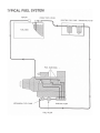
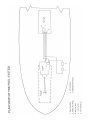
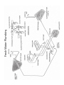
10.1 Fuel
uel System
The best maintenance and single most important precaution you can do for your diesel engine is ensure that you do
not have dirty fuel, secondly make sure all water and fuel lines are absolutely airtight.
To prevent dirt contamination in the tank, the fuel pick-up tube is positioned a short distance from the bottom of
the tank, thus allowing sediments to settle. It is advisable to clean out the fuel tank annually.
Use the fuel system diagram, be sure to understand and identify the pump, filter and all the fuel lines.
Tank Cleaning Operation
• Drain the fuel tank by disconnecting the fuel feed from the fuel pump to the engine. Connect the
same diameter hose (USCG approved) to the fuel pump leading to a large fuel container (preferably 5
gallons). Turn ignition on. This will operate the fuel pump. Do not ‘turn’ the engine over.
Once the fuel has stopped running turn ignition off. Only perform this operation when the tank is
almost empty and proceed with caution.
• Once drained, unscrew inspection hatch on the tank and use a cloth to remove the small amount of
fuel sediment remaining in the tank. Any inaccessible area can be reached by a ‘wick stick’ available
at most marine stores.
• Dispose of fuel sediment in an approved location. It is a US federal offense and liable to a heavy fine to
throw it overboard. (See Environmental Considerations section 13.0).
General System Maintenance Antifungal
• We advise the addition of an antifungal agent to the fuel tank which can be purchased from any
marine retail store. This also helps by emulsifying small amounts of water within the fuel. Be
careful to read the instructions before application.
Water Condensation
• Condensation build-up happens in all fuel tanks. It is important to check the water separator each time
the engine is used. Excessive water in the separator will allow water to pass into the injector system,
causing irrepairable damage. We would advise that the tank should be topped off when possible to
reduce condensation from occurring.
Air Lock
• The exclusion of air from the system is imperative. The fuel lines are USCG approved hoses
secured with corrosion resistant hose clamps. These should be checked on a regular basis.
• The complete fuel line from the pick-up tube in the tank to the engine injectors must be
completely airtight, or air will be induced and create an air lock which will cause the engine to stop
due to fuel starvation. It is always a good practice not to put sail covers on until the yacht is
docked/moored, just in case of engine malfunction.
Bleeding of Fuel Lines
• The bleeding procedures can be found in the Yanmar Manual. (Follow the diagram provided). A set of
tools should be easily accessible in the event of an air lock, and ideally the bleeding operation should be
able to be performed by more than one crew member.
Fuel Filters
• The Racor fuel filter is located adjacent to the mechanical fuel pump. (See plan veiw of fuel system
diagram). The fuel bowl of the filter should be periodically checked, removing any dust and
water deposits from the bottom of the trap. The filter needs to be renewed every 300 engine hours or
as conditions warrant. The secondary filter on the engine needs to be replaced in accordance with the
Yanmar operators manual.
Fueling Procedures
The following safety precautions should be followed at all times:
•
•
•
•
•
•
•
•
•
•
Secure the boat to the dock with the use of bow, stern and spring lines.
Close all hatches and ports.
Shut off all electrical equipment at the battery switch, including the bilge pump.
Wipe the fuel fill cap clean with a cloth and unscrew, being careful not to introduce dirt or water into
the tank.
Place the fuel fill nozzle into fill pipe ensuring contact to neutralize any static build-up that
might cause a spark.
Fill slowly and remember not to overfill as marine fuel expands with temperature.
Keep an eye on the total gallons on the fuel pump. An indication of the tank having
reached capacity is a feedback sound from the fill hose.
After fueling, replace fuel cap and wipe off any spillage. Go below decks to check for
fuel in the bilges and accumulation of fumes. If either fumes or fuel are present
correct the situation before proceeding by opening all hatches and ports to ventilate
the boat.
In the event of a serious spillage, stop fueling immediately, replace fuel cap and
notify attendant.
DO NOT fuel during electrical storms.
In remote areas, check quality of fuel before filling tanks. Do this by filling a small transparent glass
bottle or cup and check for particles and water. Contaminated fuel tanks are difficult to clean.
NOTE: Due to the “V” shaped bottom section of the fuel tank the fuel gauge will give an inaccurate
reading. You will appear to use very little fuel at first, then it will appear to go very quickly.
NEVER HAVE ANY LIT OBJECTS- LAMPS, CIGARETTES ETC WHEN HANDLING FUEL
10.2 Exhaust System
The exhaust system has been designed for easy access and inspection of the whole system.
Caution
We advise all operators of the vessel to familiarize themselves with the function of the exhaust system. In the
event of any exhaust gases being detected in the cabin or locker compartments, stop the engine when safe to do so and
immediately ventilate the area, by opening all hatches and ports.
THE ACCUMULATION OF CARBON MONOXIDE GASES CAN BE LETHAL.
To fully understand this system follow the diagram which accompanies this section. All connections are double
clamped to produce a secure seal for both water and gas.
The engine cooling raw water is discharged into the exhaust loop where it mixes with the exhaust gases. It is then
passed through a wire reinforced hose to the water lock muffler, which is located at the lowest point of the
system. The muffler is a plastic container and its function is to hold the water present in the exhaust system, acting
as an effective silencer. From the muffler it is pushed up over the high point (loop) of the system by the exhaust
gas pressure and out of the exhaust outlet. The system is looped to prevent seawater from flowing back into the
system in unfavorable weather conditions.
The muffler can be drained by its drain cock. It is important that after prolonged cranking {10 seconds)
you must drain the muffler. Cranking introduces water into the system and it accumulates in the muffler and is
not forced out until the engine turns over and “fires” up as usual. This drain cock is also used in the Seasonal
Decommissioning. (See Seasonal Decommissioning, section 12.9).
The antisiphon device is located at the top of the loop that leads from the engine heat exchanger and back into the
exhaust loop. This device prevents syiphoning of the raw water through the intake valve when the engine is stopped.
It is important to check the antisiphon valve on a regular basis. DO NOT over tighten the screw piece because
distortion of the rubber valve inside will affect the workability of the device. Clean the valve on a regular basis
using fresh water to remove the build-up of salt deposits. Spare valves are available directly from your dealer
or Pacific Seacraft.
10.3 Pedestal System Steering
The owner and crew should be thoroughly familiar with the operation and maintenance of all the steering system
equipment and engine controls. If the steering system makes any strange noises, binds or reacts differently than it has
done previously, you must find the cause immediately and correct the problem.
Maintenance
To maintain the moving parts in the top of the pedestal, it is necessary to remove the compass and its cylinder. For
proper alignment when re-installing the compass, we recommend placing three or four lengths of tape to over lap
on the pedestal and compass. Slit the tape before removing compass, align the strips of tape when re-installing the
compass for visual realignment. Your compass must then be checked out for accuracy by a qualified compass
installation mechanic.
Lubrication of needle bearings should be done by squeezing Edson Teflon Lubricant into the holes located on top of
the bearing housings inside the pedestal bowl. Spin the wheel when squeezing the lubricant in order to make sure
the entire bearing is serviced. Winch grease or water pump grease can be used as an alternative, but don’t let the
bearings run dry. Do not over grease as it will run onto the brake pads. Oil the chain with #30 weight motor oil.
Do not grease chain as it does not penetrate the links.
Inspect the condition of the quadrant wire, and lubricate it on a regular basis. Edson recommends placing about five
layers of tissue paper on the palm of your hand, squirt oil (general household type) on the tissues and lightly
oil the wire. This will lubricate the strands and will also “flag” a broken or hooked strand by tearing off a small
section of tissue. If you do have wire break, replace the wire immediately. (Caution: Wire splinters can cause
painful cuts). Replace the wire after 5 years. If still good, keep the old wire on board as a spare.
Security of the Quadrant Stops
The steering system is provided with stops to prevent excessive rudder travel. It is important that the system is not
forced against these stops, otherwise serious damage can occur.
See decommissioning section 12.9 for:
• Waterproof axle grease in gudgeon.
• Zinc teardrop inspection and renewal.
• Protecting rudder from direct sunlight.
• Check packing gland, grease and change flax every haul out.
Steering Wire Tension
To check for proper wire tension, lock the wheel in position by using the pedestal brake. Wire tension is best when
you cannot move the quadrant or drive wheel by hand with the wheel locked in place. Over tightening will greatly
reduce the sensitivity of the system.
Screws, nuts, bolts, as well as clevis and cotter pins that are part of the steering system, engine controls or
pedestal accessories, must be checked regularly for tightness and wear. Failure to inspect all steering parts, engine
controls and pedestal accessories may cause loss of control or failure of the engine or steering system.
Emergency Tiller
All Pacific Seacraft boats have an emergency tiller. Owner and crew must be familiar with its
location and operation. An emergency tiller drill is just as important as a man-overboard
drill. The location of the emergency tiller is the responsibility of the owner. We recommend the tiller to
be secured by quick release clips in a location which is readily accessible at all times and known to all on board.
In the event the emergency tiller is to be used, remove the cover plate located directly above the rudder and slot
the emergency tiller in place. We strongly recommend you practice this drill so it can be performed quickly in an
actual emergency.
General Use
On a new boat and at least once a year, inspect the steering system when under a strong load. On a calm day and
under power, with an observer watching from below, put the wheel hard over at full throttle. The maintenance
man should watch carefully for all pars of the system bending, distorting, creaking, or giving any indication of
failing if placed under a heavy load for a period of time. If something does fail or needs adjusting, return to the dock
for immediate repair.
It might be advisable to mark the rudder centerline position of the wheel with tape, this will be helpful when
leaving the dock, etc.
When leaving your boat at her mooring or slip, make sure that your wheel is braked
(tiller models tied off).
NEVER LEAVE THE STEERING SYSTEM TO FREE WHEEL. WHEN DOCKED OR
ANCHORED
1 0 . 4 Thru
hru Hull Fittings
Apart from the depth sounder and knot meter, all thru hull fittings on or below the waterline are secured by
seacocks.
The seacocks are an important safety device since they are the only way to stop the flow of water into the hull in
the event of a hose/pipe failure.
All thru hull flanges and seacocks are solid bronze. They have all undergone stringent testing by the manufacturers
and the seacocks are listed by Underwriters Laboratories approval rating.
They are fitted with sealrd wood compression washers, which are maintenance-free. Heavy duty hoses are used
and secured by two stainless steel hose clamps at each connection.
Pacific Seacraft strongly recommends each owner to form a thru-hull boarding and departing checklist
procedure to follow every time the vessel is used.
It is important to remember before starting the engine to make sure that the engine cooling intake seacock is
open. If not, this will result in serious damage to the engine.
A further point to note is the importance to close the head seacock when not in use, or while the owner is asleep
or off the vessel. This is due to the fact that the head bowl is on the similar level to the water line; thus if leakage
occurs flooding will result!
It is always good practice to open and close all seacocks on a regular basis to minimize corrosion thus lessening
the chance of jamming, If the vessel is left unattended in the water all seacocks should be left closed, except the
cockpit and deck drains which should be left open so no exterior water will accumulate.
It is imperative that all seacocks are maintained on a regular basis. This includes:
• Checking that all hose clamps are tight and free from corrosion.
• Checking that all seacock assemblies are firm (not sloppy or over tight)before launching.
• The full movement of the seacock arm should be no more and no less than 90 degrees plus the movement
should be firm to operate.
For the Seasonal Decommissioning Process - See Seasonal Decommissioning section 12.9.
THRU HULL SPECIFICATIONS
To help you maintain and understand the workings of the plumbing systems, study the side profile of the yacht and the
thru hull diagram.
Pacific Seacraft has made a conscious effort to keep the valves and hoses in an accessible area so that inspection and
maintenance can be carried out with relative ease.
The following information and diagrams will enable you to understand the layout and maintenance of the system:
Head Compartment
Sink Discharge
Head Intake
Head Discharge
Shower Discharge
Valve Size
3/4” Seacock
3/4” Seacock
1-1/2” Seacock
3/4” Valve
Hose Size/Type
3/4” Hardwall Hose
3/4” Hardwall Hose
1-1/2” Hardwall Hose
3/4” Hardwall Hose
Galley Area
Sink Intake
Sink Discharge
Electric Bilge
Deck Drain
Manifold 1/2”
1-1/4” Seacock
3/4” Valve
1-1/4” Thru Hull
1/2” Clear Hose
1-1/2” Hardwall Hose
3/4” Hardwall Hose
1-1/2” Hardwall Hose
Cockpit Compartment
Cockpit Drain
Exhaust Discharge
Manual Bilge Pump
1-1/4” Seacock
1-1/2” Thru Hull
1-1/4” Seacock
1-1/2” Hardwall Hose
1-5/8” Hardwall Hose
1-1/2” Hardwall Hose
All seacocks are labelled for your clarification
on the boat.
10.5 Gas System
The propane tank is located in a specially designed propane locker in the stern which is independently ventilated from
the rest of the boat. It is important not to stow any other equipment in the propane locker.
Note: Propane is heavier than air, thus will ‘sink’ to the bottom of its enclosed compartment. Propane does
not have an “odor”, you cannot smell it if it leaks. With this in mind, never store gas bottles in any cabin
compartment other than the propane locker.
Your propane cylinder has been certified according to Department of Transportation (DOT) and American
Society of Mechanical Engineers (ASME) regulations. Never attempt to modify the cylinders, and if you suspect
the cylinders to be faulty discard and replace.
Parts to be Identified
A cylinder supply valve is located on top of the propane cylinder to shut off the supply of gas to the system. A
pressure gauge is located on top of the cylinder to measure the amount of gas remaining in the cylinder.
The pressure regulator is located at the cylinder and is pre-set and must not be adjusted.
The solenoid shut off valve is located in the propane compartment. It electrically shuts off the flow of gas to
the appliances. This valve is operated from the remote panel in the cabin adjacent to the stove, which in turn is
powered by a circuit breaker mounted on the main switch panel. The breaker must be in the “ON” position
for the valve to operate.
CAUTION
THIS SYSTEM IS DESIGNED FOR USE WITH
LIQUEFIED PETROLEUM GAS (LPG) ONLY. DO NOT
CONNECT COMPRESSED NATURAL GAS (CNG)TO THIS SYSTEM
•
•
•
•
•
•
Keep the cylinder valve closed when boat is unattended. Close this valve immediately in any emergency.
When on board, both cylinder and solenoid valves should be closed when appliances are not in use.
Be sure all propane appliance valves are closed before opening cylinder and solenoid shut off valves.
Test for system leakage each time the cylinder supply valve is opened for appliance use. We suggest the
following method:
– Close all propane appliance valves.
– Switch solenoid shut off valve to the “ON” position.
– Open, then close cylinder supply valve.
– Observe pressure gauge at the regulating device and see that it remains constant for not less than five
minutes before any appliance is used.
Test system for leakage if boat has been unattended for a period of time and after any emergency in
accordance with paragraph above. Repeat the test for a multi-cylinder system.
NEVER USE FLAME TO CHECK FOR LEAKS!
To check for propane leaks, apply a soap solution over the suspected area and check for bubbles.
Test for correct solenoid operation by listening for a discernable click when the switch is turned on. If
malfunction is detected contact your dealer or Pacific Seacraft.
If a leak is detected:
• Turn off all electrical power including the auto bilge pump.
• Disconnect shore power.
• Turn the solenoid remote panel to the “OFF” position.
Check all lines for rupture and seek professional assistance.
DO NOT USE A PROPANE APPLIANCE WITHOUT ADEQUATE VENTILATION IN THE BOAT. KEEP
PORTS AND HATCHES OPEN TO ALLOW A CONSTANT FLOW OF AIR. CARBON MONOXIDE IS GIVEN
OFF AS A PRODUCT OF COMBUSTION WHICH CAN CAUSE ASPHYXIATION.
10.6 Electrical Systems
The electrical system of your boat can be divided up as follows:
• 12 volt DC System
• 110 volt AC System
• Lightning Ground (optional)
• Single Side Band Ground (optional)
• Galvanic Corrosion Protection
CAUTION: YOU SHOULD USE EXTREME CAUTION WHEN WORKING WITH EITHER
SYSTEM SINCE WORKING WITH ELECTRICITY CAN BE HAZARDOUS.
12 VOLT DC SYSTEM
A 12 volt DC electrical system is utilized throughout the boat. This provides power for lighting, pumps and
various accessories.
Central to this system is the boat’s electrical panel. Installed on the panel is a DC voltmeter to record battery
voltage. A ‘battery status’ switch on the panel allows the voltage to be checked from each individual battery
bank. Also fitted is an ampmeter which indicates the draw of electrical energy from the batteries to the various
electrical circuits which are ‘open’. The magnitude of the amp flow is directly proportional to the rate of battery
discharge. A low voltage reading of 11.6 volts or below on the voltmeter indicates that the batteries require
recharging either through the battery charger or engine alternator.
Individual electrical circuits are switched ‘on’ and ‘off by operating the circuit breakers. Each breaker
serves to protect the circuit in the event of an overload condition or short. If an overload situation occurs and
the breaker trips the malfunction must be diagnosed before operating the circuit again, otherwise serious damage to
the circuit and device can occur. Each breaker is labelled according to the circuit it operates. The amperage
rating for the breaker is marked on the breaker housing. Each circuit is identified by a specific wire color (see code
chart) for ease of traceability throughout the boat.
Pacific Seacraft has elected to use AGM (Absorbed Glass Mat) batteries for ease of maintenance and operation.
They have superior discharging and recharging properties compared to the ‘lead acid1 type. Your gel cell
batteries will require little maintenance and should last many years, but you should be warned that they are
very sensitive to overcharging. The battery charger selection switch should never be set higher than position
number three when recharging the batteries, otherwise irreversible damage will occur. (Please refer to the
Manufacturer’s manual).
BATTERY SWITCH SETTINGS
The 12 volt electrical system is switched ‘On’ and ‘Off through the main battery switch, which is located near the
main electrical panel and has four positions.
It is standard practice to designate the batteries into separate “Banks” (groups). The following battery switch
positions are most commonly used:
• Battery switch position “1” selects the engine and generator start batteries.
• Battery switch position “2” domestic or “house” batteries. These are the batteries used to operate the
electrical appliances on your yacht.
• Battery switch position “All” used for recharging both banks.
• Battery switch position “Off” all banks are isolated, no power for engine start or domestic.
If the cabin lights start to dim, this is an indication of a low battery charge on that bank. Or, if the battery charge
falls below 11.0 volts then the bank needs to be brought back up to charge. Batteries can be brought back upto
charge by running the engine or plugging into the 110 volt AC shore power to operate the battery charger.
Do not run down the charge of the second battery bank without making provision to bring the first bank up to full
charge, otherwise you will run the risk of having insufficient battery charge to start the engine.
Do not turn the battery switch to the ‘Off position while the engine is running, it will cause
serious damage to alternator.
Battery recharging is accomplished automatically by the engine alternator. The charging current is directed to the
battery banks via the starting motor cable to the main battery switch. The switch allows you to direct the charge
to ‘Battery 1”, ‘Battery 2’, or ‘Both’. Operating the ‘battery status’ switch on the panel will indicate when a full
charge has been achieved, usually 13.5 volts.
Accessories such as navigation instruments, stereo, radars, sat.nav.,etc can be added to the electrical panel and 12
volt DC system. This is accomplished by connecting the equipment to the fused bus bar and ground strip located
behind the panel. This bar in turn is powered by the circuit breaker labelled “NAVCOM”.
Maintenance of the 12 volt DC System is relatively straight forward and should consist of the following:
• Check that battery cables are connected tight and terminals are clean on the batteries.
• Check connections behind the electrical panel for corrosion and tightness. Periodic application of a
water repellant spray or silicone is all that is required.
• Check all ground connections particularly on the engine and ground strip behind the electrical panel.
• Check the starter solenoid connections to be sure they have not loosened up.
110 VOLT AC SYSTEM
The 110 volt AC shore power system is functional only when the boat is plugged into a dockside receptacle, via a
shore power cord (except generator models). The system has been designed for a single phase, 30 amp, 125
volt service. No other type of service must be connected. If in doubt, consult with the dockmaster or
marine office.
Central to the AC system is the electrical panel. A voltmeter records the condition of the line voltage from the
dock receptacle, and an ampmeter indicates the amps being drawn by 110 volt equipment on board the yacht. The
individual circuit breakers are protected by a 30 amp master breaker. A reverse polarity light is located adjacent
to the master breaker. If the master breaker should trip, or the red polarity light indicates, the system must
be shut down immediately and the malfunction diagnosed by a qualified electrician before switching the AC system
back on again. A reverse polarity situation is usually traceable to a faulty shore base power supply or a faulty
appliance. A tripped breaker indicates a direct short on board the boat. The individual circuit breakers are tagged
and protect the circuits against load malfunction.
The 110 volt AC System is ‘grounded’ through the shore power receptacle(s). Never plug your shore power
cable into a dockside electrical service that is not ‘grounded’. If in doubt, ask. The boats’ outlet circuit is
further protected by a Ground Fault Circuit Interupter (GFCI). This GFCI looks like a regular outlet, but has
reset buttons. The GFCI will sense any stray currents and will immediately shut the circuit(s) down. To
reactivate the circuit(s) the GFCI needs to be reset after the malfunction has been determined. Know where
the GFCI is located so you can reset it if it is tripped.(Please refer to the manufacturer’s operating and testing
instructions).
Care and good judgement must be exercised in operating any 110 volt device in the vicinity of water, otherwise
serious consequences can result.
CAUTION
The outlet receptacle in the head is the weatherproof type with hinged covers. The covers
should be kept closed when not in use. Under no circumstances should the covers be open when
the shower is in use.
The water heater has an electrical heating element installed. Do not operate the water heater without
water in the water heater tank or serious damage to the electrical heating element will occur.
An automatic onboard battery charger has been installed (optional on some models) to maintain the batteries at
full charge. On leaving the boat for any length of time the charger selection switch should be set no higher than
position number three, otherwise battery damage can result.
Troubleshooting the 110 volt AC System should be handled by a qualified marine electrician. Working with 110
volts AC is hazardous and can require special equipment beyond the scope of the onboard tool kit.
These precautions should be exercised to avoid shock when connecting the shore power cable:
• Switch to ‘Off all 110 volt circuit breakers on the yachts electrical panel before connecting and
disconnecting the shore power cable.
• Connect the shore power cable to the boat first. (So no current flows)
Disconnect the shore power cable at the shore outlet first. (To stop flow of current)
INVERTER / BATTERY CHARGER
Before any operation is performed with the inverter/battery charger, it is imperative to read and fully understand
the owners manual.
Please contact Xantrex or Pacific Seacraft directly if you need further explanation.
It is important to understand the following points regarding usage:
• The inverter will probably not be able to support the operation of all the onboard appliances at one
time
• “Energy Management” is essential.
• Microwave cooking times will be slightly longer due to the power requirments of the oven.
Note: The inverter will drain the yachts batteries in a very short space of time. The inverter has an automatic
low voltage cut-out which activates at 10.2 volts on the Freedom 10 models and 10.0 volts on the Freedom 20. It
is good practice to physically monitor the battery charge in the event of a maifunction.
LIGHTNING GROUND (OPTIONAL)
The lightning ground provides a “cone’ of protection against direct strikes around the per meter of the boat. In
the event of a lighting strike the system has the ability to dissipate the energy back into the water via the ground
plate. The ground plate is a fused copper bead bar (a ‘dynaplate’) presenting a large surface area to the water, its
effectiveness will be seriously diminished if it is coated with bottom paint. It should be periodically cleaned with a
stiff wire brush. After a suspected lighting strike the whole electrical system of the boat must be checked system
by system for continuity and correct operation.
SINGLE SIDE BAND GROUND (OPTIONAL)
The SSB ground provides an efficient grounding plane to pulsate short wave communication signals off the
earth’s ionosphere. The system consists of a two-inch wide copper band which is bonded directly to the inside of
the hull shell. The band runs around the sheer of the boat, port and starboard of the hull centerline and also from
the side stays to the centerline. All chainplates are directly connected to the system. Contact with the seawater is
afforded by the system’s direct connection to the keel bolts and the
ballast keel. (On encapsulated keels like the Flicka and Dana this contact is through a ground plate).
GALVANIC CORROSION PROTECTION
Zinc anodes are installed on two locations; the propeller retaining nut and rudder gudgeon. These locations
are critical since two dissimilar metals, bronze and stainless steel, come into contact with each other. The zincs
protect the bronze from wasting away through chemical reaction with the steel. The zincs should be inspected
on a regular basis and replaced as required. The zincs are available directly from your dealer or from the
factory. Excessive zinc loss is usually an indication of an electrical malfunction which requires further
investigation by a qualified electrical technician.
LIGHTING REQUIREMENTS - Crealock 34
Interior
Brass Berth Light
Dome Light (Brass)
Dome Light (Chrome)
Chart Table Lamp
Flourescent Light
Day/Night Dome Light (Optional)
Supplied By
Seadog Line
Seadog Line
Seadog Line
Aqua Signal
Aqua Signal
Seadog Line
Order No
400400
400195
400100
3132012
3130042
400350
Wattage
15
15
15
5
8
15
Exterior
Combination Bow/Deck Light
Port and Starboard Bow Light
Stern Light
Mast Light (Standard)
Tricolor Anchor/Stroke
Forespar
Hellamarine
Hellamarine
Perko
Aqua Signal
ML2
2LT002386-01
2386
1197000CHR
33547-95
20
25
10
10
10 & 25
The above information will help you when ordering new fittings or bulbs. They can be ordered direct from the
manufacturer or from Pacific Seacraft.
WIRING COLOR CODE
Description
Ground
Running Lights
Bow Lights
Anchor Lights
Spreader/Foredeck Light
Tri-Color Light
Cabin/Reading Lights
Pressure Water Pump
Bilge Pump
Sump Pump
Nav/Com (Instruments)
VHF Radio
Battery Test
Spares
Strobe Light
Wire Size (AWG)
12
12
12
12
12
12
12
10
10
10
14
14
14
12
12
Color
Black
Red
Green
Yellow
Pink
Orange
White
Brown
Brown
Brown
Purple
Purple
White/Red
Blue
Blue
10.7 BILGE PUMPS
MANUAL PUMP
The manual bilge pump is located in the cockpit near the steering station. The handle is equipped with a cord which
should be tied securely to the eye provided on the pump housing so it is readily available. Pacific Seacraft chose
the Whale Gusher bilge pump, due to its simplicity, reliability and effectiveness.
To Operate
Place the handle into the central socket. Using full strokes raise and lower the handle. The first several strokes
will feel light as water is drawn up from the bilge into the system. Keep pumping until the stroke resumes
a light movement. This will indicate that the bilge is empty. We advise checking the bilge to confirm this. It is
normal for a small amount of water to “return” to the bilge from the pump.
Problems May Exist If Pump Fails To Prime
• Check that inlet hose connection are air tight, free from blockages and does not collapse during
the suction stroke.
• Inspect pump diaphragm - replace if damaged.
• Solid objects in the body of the pump will prevent proper operation by obstructing the valves. The
foreign matter should be removed to prevent further damage.
• Inspect inlet and outlet valves for blockages. This can be accomplished by removing the inlet and
outlet hose, inserting a finger or screw driver to remove debris.
Reassemble and test.
• For further information, refer to manufacturers service sheet in separate manual.
ELECTRIC BILGE PUMP
The electric bilge pump is located beneath the cabin sole inspection hatch positioned on top of the the keel.
The pump is operated from a separate control panel near, but independent of, the boat’s main electric panel. The
pump switch has three settings:
• The central setting is “OFF” - no pumping.
• Push the switch to the right for “ON”. The switch has to be held in this position for constant
pumping. It will automatically return to “OFF” when pressure on the switch is removed.
• Switch to the left - “AUTOMATIC” - pumps only when the floatation switch is activated by
the amount of water in the bilge which in turn operates the pump until the water is discharged. It is
a normal practice, if the vessel is to be left unattended for a period of time, to leave the automatic bilge
pump on “AUTOMATIC”.
The hose leading from the electric pump to the bilge discharge is fitted with an anti siphon device. This is
located at the deck before the discharge. It prevents sea water siphoning into the bilges from the ocean. Check this
device on a regular basis. Do NOT over tighten the screw piece because distortion of the rubber valve inside will
affect the workability of the device. Clean the valve on a regular basis using fresh water to remove the buildup of salt deposits.
IMPORTANT: ONLY USE A 9-AMP FUSE.
BURN WITH SERIOUS CONSEQUENCES.
FAILURE TO DO SO CAN CAUSE THE PUMP TO
For further information on the electric bilge pump, consult the manufacturers information leaflet supplies.
Maintenance of Bilge Area
Being the lowest accessible part of the yacht, the bilge tends to collect all sorts of debris. It is important that the
limber holes are kept clear so that there is free drainway to the lowest part in the boat, and that the cabin sole is
brushed and debris collected on a regular basis to prevent accumulation in the bilge.
A regular inspection of the bilge is necessary to ensure that no debris is blocking or interfering with the bilge
pump floatation switch.
The bilges can be cleaned out using a biodegradable bilge cleaner. (See your local marine hardware store). Do NOT
pump any unacceptable substance into the ocean. (See Environmental Considerations section 13.0).
10.8 Plumbing
Fresh Water Pressure System
Two integral water tanks feed the freshwater system. These are located under the quarter berth and forward
berth. (Refer to the specification data in section 5.0).
The pressure water system is operated by a breaker on the 12 volt DC panel. Once the system is switched on the
pressure pump maintains a predetermined pressure of 20 psi. The pressure is kept constant by the accumulator tank
which smooths the water flow and reduces on/off cycling of the pump by lessening the variation in pressure and
flow between the pump and the outlets in the system. The volume of this tank is 1.3 quarts (1.2 liters).
Both water tanks have hoses which are clamped to the manifold (see diagram called “Fresh Water System”)
under the galley sink area, adjacent to which the accumulator tank and the pressure pump are also located.
It is important to only have one water tank in use at any time. We suggest you use the bow tank first. This will
prevent siphoning between the tanks and also prevent air from entering into the system.
The foot pumps are installed (galley and head sinks) for use as a back up and to conserve both water and electric
power. The valve to the foot pumps are located on the manifold (se3 “Fresh Water Plumbing”diagram) should be
kept in the closed position when underway or until needed. Switch off the pressure water system when not in use to
avoid water loss due to an unanticipated system rupture.
Head Plumbing and Black Sewage Handling
The US government requires all US yacht manufacturers to install holding tanks or approved waste treatment
systems to prevent pollution. Pacific Seacraft boats are fitted with an integral fiber glass tank located adjacent to
the head. (See Systems Lay Out Plan).
Note: Articles such as paper towels, sanitary napkins, matches, etc. will clog this system. Never dispose of
them into the head.
Head/Holding Tank Discharge Procedures
There are four different discharge settings for the head system:
• Head to Holding Tank
• Holding Tank to Deck Pump Out (shore)
• Head to Overboard (outside 3-mile exclusion zone)
• Holding Tank to Overboard (outside 3-mile coastal exclusion zone)
To help understand the following procedures, follow the Head Plumbing diagram provided.
Head to Holding Tank
Check that head discharge thru hull and shut off valve are closed. Open diverter valve and intake (either “head
intake” thru hull or “intake shut off” valve) then flush head. Once flushing is completed, close intake.
Holding Tank to Deck Pump Out
This operation should only be performed when the vessel is securely moored to the dock. Close “diverter” valve and
“shut off” valve. Unscrew deck cap marked “waste”, and place pump out vacuum hose in waste hole and proceed
with dockside pump out operation procedure. Replace “waste” cap once operation is completed and wash off any
spillages which might have occurred.
Head to Overboard
To enable direct head overboard discharge, close the “diverter” valve and check that the “shut off” valve is closed.
Open head discharge thru hull seacock and then flush head. This must only be done outside the 3-mile exclusion
zone. (See Environmental Considerations section 13.0). Once operation is complete close head discharge thru hull
and head intake thru hull (or intake shut off valve if fitted).
Holding Tank to Overboard
Keep diverter valve (holding tank intake) closed. Open shut off valve and open head discharge thru hull. Operate
manual overboard discharge pump until the holding tank is empty. Reset valves to desired positions. Only
perform this operation outside the 3-mile coastal zone. (See Environmental Considerations section13.0).
General Head Information
All Pacific Seacraft boats have sea water flushing as standard. This system should only be operated outside the
3 nautical mile coastal limit. (For vessel users exclusively in the Great Lakes, it is illegal to dump anything
except fresh fish, fish parts, dishwasher, or grey water anywhere regardless of distance from shore). (Refer to
Environmental Considerations section 13.0).
All hose connections are double clamped. Both clamps and pipe work need to be checked from time to time against
corrosion. We would suggest the cleaning of the holding tanks on a regular basis. Use a strong marine approved
detergent. An anti-siphon device is located at the deck. It is important to check the anti-siphon device on a
regular basis. Do not overtighten the screw piece because distortion of the rubber valve inside will affect
workability of the device.
For head flushing procedures please refer to the manufacturers flushing instructions.
Grey Water Sewage
Grey water sewage is defined as drainage from shower, ice box, galley and head sink. This waste can be released
into the ocean with no limitation. Pacific Seacraft would recommend the use of bio-degradable dishwashing liquids,
soap and cleaning agents. The shower sump requires a pump since its drain is at the same level as the thru hull and
waterline.
Shower Sump Pump
The sump pump is operated from the 12 volt electric panel and is activated by a pull switch in the head
compartment. The pump and pump filter are located under the head sink.
The sump pump is self priming and uses corrosion resistant materials throughout. The purpose of the filter is to
stop debris from passing into the pump. The filter is adjacent to the pump and has a clear collection bowl for easy
visual inspection. The sump pump filter needs to be cleaned on a frequent basis for the pump to function properly.
Always pump shower water (grey sewage) away after use. Do not leave it in the sump.
To Operate The Shower Sump Pump
The sump pump will make two different pumping sounds. The first will be a high pitch due to the pump self
priming. Once primed, the tone will lower until the water is discharged. Eventually the tone will return to the
higher pitch indicating total discharge of grey sewage from the system.
An anti-siphoning device is fitted between the sump pump and the seacock. Like the electric bilge pump it is
located at the top of the hose loop. Carry out the same maintenance procedure as for the electric bilge antisiphon device, described previously.
Maintenance of the pump is minimal. Check the connecting rod bearing annually and add chasis lube as needed. No
other lubrication of the pump is required. The filter gasket needs to be checked and if it shows signs of wear it
should be replaced.
For further troubleshooting problems, consult the service sheet for this pump located in the separate manufactures
manual.
10.9 Ventilation System
Dorade Vent
The standard dorade vent is a flexible white PVC
rubber fitting located on the cabin roof top which
allows the flow of fresh air to below decks. The
cowl can be rotated thru 360° by unscrewing its
anodized aluminum retaining rings. Located below
the cowl is a Vetus water trap. This trap will
prevent water from coming below even in heavy
weather, but it is advisable to rotate the vents aft
or away from the prevailing weather. A cover plate
is supplied for watertight closing of the cowl
ventilator.
We advise the owner/operator to always keep in
mind that sheet entanglement can damage the cowl.
The cowl can be removed and the upper flange of the
base plate can be loosened easily by hand. Be careful
not to damage the mosquito screen.
The cowls are relatively maintenance free.
Periodically wash with warm soapy water and a
cloth inside and out.
To open and close the vent from within the main
cabin, turn the screw handle located in the center of the vent and adjust to your own comfort. This can be seen
with the accompanying diagram. (Cowl Vent)
Propane Locker Ventilation - (See Gas System section 10.5)
The propane locker is independently ventilated from the rest of the boat. There are two drain holes at the bottom of
the propane locker to allow the flow of air into and out of the locker. Propane is heavier than air and will sink to
the bottom of the locker. It is imperative not to block the drain holes for this reason.
The storage of any other equipment in the propane locker is not recommended.
When using a propane appliance it is important to have the boat freely ventilated and make sure
propane gas is stored only in a propane loker that is vented overboard.
Never Use A Propane Appliance As A Heating Device.
Engine Compartment Ventilation
There is no special engine compartment ventilation. The engine uses the air from around the engine space. If the
engine is operated in extreme heat, open the engine compartment top
Ports (windows)
The ports are made of high tensile magnesium bronze, with tempered glass and are self-draining. The glass is
set into a rubber gasket which in turn forms a watertight seal against the port body. The rubber gasket needs a
periodic wipe with silicone to preserve the rubber. The glass can be cleaned with a non-abrasive household glass
cleaner. The hinges and dogs need to be treated with a light oil to maintain ease of use. It is imperative to
exert equal pressure on the dogs against the gasket to prevent torquing the lid. The lid should be tightened down to
the stops to maintain a water tight seal.
Hatches
The Bomar hatches fitted on your boat are constructed of the strongest, lightest and the least corrosive of any
aluminum alloy (Alumnag 35). This alloy provides great resistance to salt water and pressure. The gasket
forms a watertight seal. The glazing material (Dupont Lexan) is stronger than glass and is virtually unbreakable.
For extra privacy, it has a dark smoke color tint that lets in 80% of the available light and still allows a clear
view out.
The following precautions will prevent accidents and reduce the chance of damaging the hatches:
• Open and close hatches carefully. Do not force or put unnecessary pressure on any part of the hatch.
• Close all hatches while sailing. Jib sheets can catch on the hatches, plus serious injury can be
caused to crew falling through them! Hatch catches can easily be damaged. When dogging down, do not
use excessive force.
• The frames may be touched up with polyurethane or vinyl paint. It is also advisable to keep the
moving parts clean from salt and also lubricate using a silicone based spray.
• For regular care we advise you to fresh water rinse the hatches when hosing down the deck.
• Periodic maintenance includes washing the hatch with mild soap and lukewarm water. Polish
the glass with mild automobile windsheild polish. Hairline scratches and minor abrasions can be
removed/reduced this way.
Suggestions For Long Term Storage
When leaving the boat for an extended period of time, it is advisable to unzip the headliner to allow free flow
of air which will prevent mildew under the liner. It is also good practice to leave locker and bilge compartments
open to minimize condensation build-up. If you do leave the bilge boards open, replace them immediately upon
your return for the safety of your crew.
11.0 Specific Manuals
The manufacturers manuals/maintenance sheets referred to in this manual and listed below can be found in the
accompanying manufacture’s manual. It is important to read these manufacture’s manuals carefully and to keep
them within reach of this owners manual for easy reference.
Engine
Seawater Strainer
Racor fuel filters
Shaft Seal
Pressure Water System
Macerator Pump
Electric Bilge Pumps
Deck Wash Pump
Accumulator tank
Electric Panel Diagram
Battery
Battery Charger / Inverter
LPG Gas Control
Stove
Compass
Depth Sounder
Knot Meter
Instruments
Water Heater
Cabin Heater
Anchor Windlass
Winch
Refrigeration
Head
Sail Care
1 2 . 0 Hull and Deck Maintenance
12.1 General
Pacific Seacraft sources materials the world over to acquire the best quality for your yacht. Once the materials
are installed in your yacht and the yacht leaves the factory it is subject to use and environmental conditions
beyond our control which ultimately leads to degradation.
The factors involved in degradation are:
Light
Light is a form of energy. The energy in light is made up of different components. Ultra violet (UV) is considered
the most destructive one for weathering. The energy in light attacks materials by trying to break them down.
This energy can cause a chemical reaction known as oxidation and is noticed as color change. This is usually a
“yellowing” or “bleach” fading of the gel coat.
Water
Water is a universal solvent. It will dissolve more things than any other chemical. Water attacks parts by
reacting with them. It penetrates materials and leeches out impurities or degraded materials, and it can also
contribute predissolved chemicals which can cause stains.
Pollutants
We do not live in a sterile environment. The atmosphere contains many foreign materials, some of these
being harmful to materials.
Temperature
Sunlight generates heat. It will raise the temperature. How much will depend on the conditions and color of your
yacht the darker the hull the higher the temperature. As the material warms up, three things happen:
• The material softens slightly.
• Additional chemical curing can take place.
• Chemical attack and water penetration rates are increased.
It is important to bear in mind that degradation in many cases is a very slow process, but we must emphasize the
importance of careful maintenance procedures which will slow down this process even further. If you follow
the following operations, it will enhance the yacht’s life and performance, and will be a joy to own and sail.
1 2 . 2 M a i n t e n a n c e B e l o w t h e Wa t e r l i n e
It is extremely important to keep the bottom of the yacht as free from marine growth as possible. To allow marine
growth to build up will not only affect the performance, but also interfere with the thru-hull fittings. The
growth of marine life will vary depending on the waters where the yacht is kept.
It is advisable to check below the waterline every month and, if necessary, wipe the bottom and propeller with a
towel or piece of carpet. If you can not undertake this maintanance yourself hire a diver to perform this operation.
Remove all stains on the waterline which might accumulate from harbor pollution by using an approved cleaner/
degreaser.
Monthly checks should include cleaning:
Waterline
Inspect Zincs
Thru-hulls
Shaft
Rudder
dder
Propeller
Keel
When the yacht is lifted, check the following items:
• The condition of the propeller, shaft, rudder, and skeg.
• Replace zinc anodes as necessary.
• Operation of the sea valves, (see Thru Hull Fittings Section 10.4)
• Rudder stock bearing (see Steering Systems Section 10.3)
• Shaft cutless bearing.
• Sea water strainer for the engine.
• Check stuffing boxes for both propeller shaft and rudder stock, replacing packing flax as necessary.
Each vessel which leaves the factory is covered by a ten (10)-year hull warranty program (See Warranty
Section section 3.0). The epoxy barrier and bottom paint system used on all boats are products of Courtaulds
Coating, Interlux and International Paints Divisions. It is important to use this same product for future
applications as other antifouling bottom paints do not have the same properties, thus jeopardizing the warranty.
Epoxy Barrier
All submerged surfaces of the boat are coated with three applications of 2000E and 2001E epoxy paint. This is
a two part epoxy coating developed to protect fiberglass hulls from water absorption.
The coating is applied by a 3/16 inch nap mohair roller in three separate coatings to a dry thickness of 7 mils
(0.007 inch). If this coating is degraded by impact, sanding, sandblasting or other types of abrasives including
chemical etchants or paint removers, it must be returned to the original applied thickness, otherwise the 10
year hull warranty will be void. We strongly advise any repairs or coating reapplications be undertaken
by qualified and properly trained personnel.
Antifoul Bottom Paint System
The antifoul bottom paint system used is called Ulta-Kote. Each vessel has two applications of this paint
system. Once the vessels leave the factory it is the responsibility of the purchaser/owner to maintain the
integrity of this coating to the original factory specifications.
To maintain the warranty, Pacific Seacraft specifies the following application of antifoul paint every year to 18
months and to adhere to the following proceedures:
Antifoul Application Procedures
•
•
•
•
•
•
•
Remove yacht from water and place in secure cradle.
High pressure fresh water wash and wipe antifouled bottom paint area with towel or piece of carpet to remove
bacterial slime. The use of abrasive scrubbing with a stiff brush or abrasive sponge will actually remove the
toxic particles of the paint causing premature failure of the coating.
Sand antifouled area with 80 grit dry sand paper. Remove growth layer only. This will form an even
bonding surface for the antifoul bottom paint to adhere.
Wipe entire surface with 216 Interlux Special Thinner, this will remove sanding residue. Repeat the
application if surface dust is still present. See Specifications Of Vessel (section 5.0) for approximate wetted
surface area
Before application of Ultra-Kote 2449N, stir thoroughly. Continue to stir while using. Interlux
recommends the use of a hair paint brush as the best applicator.
Allow the first coat to dry for a minimum of 12 hours Then apply second coat and also allow it to dry for 12
hours.
Dont forget the hull areas hidden by the cradle supports must be treated in the same manner.
Note: The yacht should not be out of the water with a new paint application for more than 60 days.
The climate conditions for the application of antifoul bottom paint must be dry, do not apply while the hull is
damp, wet or in wet weather conditions.
The theoretical coverage for 1 gallon of antifoul bottom paint is 350 square feet per coat.
Pacific Seacraft strongly advises the applicator to follow the manufacturers application and safety
instructions.
For further details about the warranty and the epoxy coating, refer to the Warranty Section, (section 3.0)
1 2 . 3 Maintenance Above the Waterline
Hull
To help maintain a good exterior above the water line, wash with fresh soapy water and a cloth. Hose down with
fresh water, allow to dry, then apply a good marine wax (Meguiars or equivalent). This operation should
be carried out at least twice a season. Do not use any abrasive cleaning agents or materials on the gel coat, and
always wash all detergents off thoroughly.
We do not recommend the use of an electric buffing machine, as this can easily “burn” the gel coat.
Deck
Wash the decks in the same manner as the hull, but do not wax the non-skid or any other horizontal surface on
which people walk as it will make the surface slippery and hazardous. Again, do not use a detergent or degreaser
(non abrasive). If possible, wash deck and hull with fresh water and deck brush after each use to remove salt
residues.
Your marine hardware store will have a large selection of cleaning and waxing products. They should be able to
advise you on the best to use. Once a specific brand has been chosen, it is a good idea to continue using that brand.
Exterior Teak Wood
Teak is not maintenance-free, but is an incredibly resilient and tough wood containing natural oils. The overall
condition of the teak wood can enhance or diminish the appearance of your boat.
The small amount of time spent caring and maintaining your teak on a regular basis will not only be pleasing to
the eye, but also add valve to your investment when you come to sell.
All exterior teak has been treated with an application of coconut teak oil or three coats of varnish before leaving the
factory.
To look its’ best, exterior teak needs frequent attention. Frequent washdown with fresh water will prolong the
life of the oil or varnish, but further applications of oil or varnish are also essential. We would recommend
three plus applications of teak oil a year, but this will all depend on the marine environment where you keep
your yacht. For varnish, Pacific Seacraft recommends a further three coats to be applied on receipt of the yacht,
and further coats when necessary. Consult your dealer or a professional as to the best proceedure to follow.
When applying any oil, carefully follow the manufacturers’ instructions. We advise masking off of all
associated gel coat areas, (however an oil spillage can bleed under the edges of the tape.) Over time teak oil can have
a darkening effect on the gel coat. If a spillage does occur wash off immediately.
The best prevention of teak oil spillage is careful application.
1 2 . 4 Deck Hardware
DECK FITTINGS
General
All deck fittings used are of the highest quality. Cleats, ports, winches, etc. are of solid bronze with the option of
chrome plating.
The lifeline stanchions and all other deck fittings are thru-bolted to the deck and reinforced with full backing
plates and caulked on both sides. We advise deck hardware to be washed frequently with fresh water to remove the
build-up of salt and grime, and periodically polished with a metal cleaner.
MAINTENANCE AND CARE
Cleats & Chocks
There is little maintenance involved, apart from washing with fresh water followed by a light silicon based
lubricant spray.
Lifelines and Stanchions
A regular check of the lifelines and stanchions is essential for the security of the crew. Attention must be paid
to the cotter pins and split rings found on either end of the lines. If these look in any way worn or corroded it
is imperative to have them replaced. The pelican hooks located at the boarding gate must be checked for correct
functioning on a regular basis, to be sure that the plunger has complete freedom of movement.
Check all swaging for dents or cracks and replace as necessary.
The lifelines should be suitably taut - not slack. They can be adjusted by the turnbuckle screw adjusters located at
the pulpits.
It is important to note that the lifelines do not last forever. If wear or corrosion has taken place these must be
replaced.
The vinyl covering the life-lines may be subject to fading.
Blocks
The blocks are made from aluminum, stainless steel and nylon. These need to be washed regularly with fresh water
and lubricated with silicon spray. A lubrication procedure should be carried out every 6 months and especially
before a long cruise.
Winches
Regular maintanance is crucial for reliable performance.
Pacific Seacraft uses Lewmar. These winches are well known for strength, durability and quality. We advise
owners to read the accompanying manual from Lewmar. It describes the servicing procedure, and explains
their one-year warranty. Should you need assistance, we would recommend you contact an authorized Lewmar
representative.
Chrome
All parts can be treated with chrome polish once the parts have been washed down with fresh water. Polish to a
shine with a clean cotton cloth.
INSTALLATION OF NON-OPTIONAL/CUSTOMIZED EQUIPMENT
It is Pacific Seacrafts1 policy not to make specific recommendations as to the installation of specialized equipment
other than equipment we offer as factory installed options. You are advised to seek professional assistance directly
from the equipment manufacturer or representative before making a final decision as to the parts applicability in
effecting the structural integrity of the boat.
MAINTAINING THE MAST
The mirror-like gloss can be easily maintained by following these simple rules:
• Wash the surface whenever practical with mild non-abrassive detergent and water.
• Solvents such as lacquer thinner or kerosene may be used to soften or remove heavy build-up of grease
and grime. Use distilled white vinegar to remove stubborn, white salt residue.
• Apply cleaning solvents with soft clean cloths. Wipe up solvent quickly. Do not allow solvent to
dry on the surface or to puddle and soak into the surface. Wash these areas with mild detergent and
water to remove solvent residue.
• Always thoroughly rinse all surfaces with fresh water after cleaning with detergents or
solvents. Latent solvent residue can attack the polyurethane while detergent residue will attract
dirt.
The following are the DO NOT’S:
• Do not use waxes. Wax build-up ages and yellows very rapidly, creating the need to maintain the
wax and causing the topcoat to appear yellow. Wax build-up also collects dirt, compounding the
problem.
• Do not use abrasives, scratch pads, or polishing compounds. Scratching the surface gives dirt a place
to cling while wearing out the resin layer, and will reduce the overall life of the finish.
• Do not allow contact between the mast and teak cleaners. Many teak cleaners contain acids and caustics
which will stain and discolor.
• Do not allow wet equipment (seat cushions, coils of line, sails, sail covers, coolers) to trap and
hold moisture against polyurethane paint topcoats. This condition can result in blistering and or
delamination of the polyurethane paint topcoat.
• Do not “shrink wrap” or tightly bind polyurethane surfaces with plastic wrappings.
When tarping a boat for storage, the cover system should be ventilated allowing the boat to “breathe”.Covers and
tarps, whether synthetic or of natural fiber, should not be pulled tight to surfaces painted with polyurethane.
This condition can trap and hold moisture on the surface and may result in loss of gloss, blistering, or
delamination.
If the mast becomes scratched or the polyurethane surface is damaged - See Mast Touch Up and Repair sections 12.7.
1 2 . 5 Sail Maintenace
Proper sail care and maintenance can increase the life of your sails. Whether you race or cruise, proper storage
and cleaning can mean the difference in speed as well as longevity. Over the last few years, sailcloth has
become increasingly firm. This finish or resin is subject to faster breakdown. It is important to keep the luffing
of sails to a minimum as this is an easy way to break the resin down.
Dry your sails by laying them on a grassy area or hanging them up if the wind is very light. Do not hang your
sails in a breeze.
Ultra-violet radiation can, over a period of time, destroy both nylon and dacron. The use of cover materials for
mainsails and roller-furling sails is a sure way to prolong the life of your sails.
Care And Storage
Chafing of seams is a symptom of modern sail cloths because the stitching stands proud of the cloth unlike the old
soft cotton cloths where stitches would lay flush. Before your first sail, and regularly thereafter, inspect all
possible areas of chafe. Chafe protection may be required in the following areas:
•
•
•
•
•
•
•
•
•
Spreader ends.
Stanchion tops.
Rigging screws.
Mast and boom fittings.
Bolt rope of genoa luff chafed by spinaker pole and sheet.
Windlass and mooring cleats.
Always fold sails properly. Do not just “stuff” them into bags. The best way to fold is in large folds
parallel to the foot in a concertina. Then roll from clew end towards tack - this will leave the tack
exposed, ready to hook on the next time you need the sail.
Do not fold sails on the same line every time, as this will cause creases.
Check head, tack and clew attachment points regularly .
Cleaning Instructions For Your Sails
Dirt or caked salt: Use a soft bristled brush and liquid detergent. Avoid hard powder detergents and stiff brushes as
they may damage the finish or stitching.
Oil, grease, tar and wax: Use warm water, soap and elbow grease. Hard stains can be removed by household
bleach or common stain remover. Be careful to thoroughly remove all cleaning solvents or they will damage the
finish.
Blood: Soak the stained portion for 10 to 20 minutes in solution of 10 parts water to 1 part bleach. Scrub and
repeat if necessary. Rinse thoroughly.
Rust and metallic stains: Scrub w i t h s o a p a n d w a t e r, a p p l y a c e t o n e , M.E.K.P.(Methyl Ethyl
Kethone Peroxide) or alcohol. Rinse thoroughly. As a last resort, dilute 5% oxalic acid with water and let
soak 10 to 20 minutes. Rinse and dry.
Mildew: Hot soapy water is usually all that is needed. If necessary, use the diluted bleach approach,
described in “blood” above. If a residual chlorine smell is still present after rinsing, a 1% solution of
sodium trisodium phosphate will remove all chlorine traces.
Paint and varnish: Acetone and M.E.K.P (Methyl Ethyl Kethone Peroxide) should remove most common paint
stains. Varnish can easily be removed with alcohol.
Use all solvents with care. Always rinse and dry thoroughly. Solvents and bleaches can damage nylon and dacron if
not removed properly.
Mylar and Kevlar sails can generally be taken care of in the same manner as their dacron counterparts. Avoid solvents
whenever possible as they can break down the adhesives used to laminate the nylon.
Washing: Wash sails in fresh water as salt will slowly damage threads and attract humidity, thus causing
mildew. It is important not to machine-wash the sails.
Note: If sail panels are punctured or became unstitched it is important to have them promptly repaired at a
sail loft by a qualified person.
1 2 . 6 Gel Coat Repairs
pairs
The repair procedures recommended here are based on accepted practices. We believe these procedures will yield
pleasing results.
The quality of the repair is directly attributable to surface preparation and cleanliness.
It is important to follow the following instructions and the material suppliers’
instructions for the mixing and application of required gel coat and other materials
needed for repairs.
The technique we describe assumes the user will follow safe working practices and follow all manufacturers’
recommendations. It is imperative to consult material safety data sheets which are found at the back of the manual,
before handling and mixing these materials. You are strongly advised to follow the safety cautions as stated in the
sheet.
Gel coat is available from Pacific Seacraft in 1 -pint quantities. Pacific Seacraft cannot guarantee an exact color
match due to fading caused by environmental conditions.
Pacific Seacraft is unable to ship any catalyst due to its oxidizing properties, but it is commonly available from
any marine hardware store. The catalyst is a colorless liquid type (Witco Hi-Point 90 or equivalent).
Both gel coat and catalyst should be stored in a dark cool place - Do not store on your boat. It is inadvisable to
use gel coat after 1 year.
MIXING PROCESS
Only proceed with the mixing operation once you have read and completely understood the safety cautions. If in
doubt, re-read or refer to a professional.
The gel coat you receive is uncatalysed. In order to harden and dry a catalyst {Methyl Ethyl Kethone Peroxide
- MEKP) must be added. Depending on the size of the repair use a suitable sized container i.e. Dixie cup. Add the
weighed gel coat and apply the catalyst at 1-1.5% by gel coat weight (3-4 drops per oz. of gel coat). Too much
catalyst will reduce the working time significantly. Mix the gel coat and catalyst together, being careful not to
introduce air into the mix. We suggest the use of a clean round stick. Once mixed, you will have a working time of
about 10 minutes before it gels.
Apply the gel coat to the area being recoated by using a stiff brush.
You may want to experiment first so that you feel comfortable in using the materials
.
REPAIR PROCEDURE
Surface Damage
•
•
•
•
•
•
•
When repairing surface damage, first clean the damaged area with solvent. Then, inspect closely to insure
that structural damage has not occurred.
Using a power drill with a rotary burr attachment, form a V-groove along the scratch. Remove flaky
edges and feather the exposed gel coated surface back beyond the damaged area. Use 100-220 grit sandpaper.
Clean the area with a dry cloth and blow off dust. Be sure not to touch the repair area with fingers or hands.
Mix gel coat with catalyst as discussed and apply it to the damaged area. Pack the material tightly to minimize
entrapped air. Overfill the scratch or hole surrounding the area by about 1/16 inch.
Cover the repair with wax paper or cellophane separating film and squeegee down.
Leave the cellophane or wax paper in place and allow the gel coat to cure completely (1 to 2 hours). Then
remove cellophane. Finish the repair by sanding with 220-600 grit wet sandpaper, followed by a number of
applications of a buffing compound and finally a waxing agent.
If you follow the instructions and the directions listed on individual repair materials, you should end
up with a coating that approaches the original in both appearance and performance.
12.7 Mast Touch Up Procedure
As with gel coat, it is imperative to read the material safety data sheet supplied and follow the advice.
Tape off areas then clean the damaged area with a moist cloth to remove any salt and grime deposits then allow
to dry. Be sure not to touch the repair area with fingers or hands after cleaning. Mix an estimated quantity of
polyurethane paint and catalyst at a ratio of 1:1 according to the size of the repair. Mix thoroughly and apply
with a hair brush.
Let it dry (1-2 hours). Smooth out with 600 wet and dry paper, buff and polish.
1 2 . 8 Interior Maintenance
BILGE AREA - See Bilge Pump Section 10.7.
ICE BOX
The ice box is insulated
with a urethane
foam to maintain the
temperatures. It is
advisable not to place any
food or perishable items
in the ice box without the
required amount of ice or
cooling blocks. This may
let odor, mold and mildew
occur.
Food items should be
placed in tupperware
containers or plastic
bags to avoid
contamination from other
items in the ice box.
At the end of each cruise
clean out thoroughly and
leave the top open slightly
to allow air flow into the
ice box.
To clear the melt water from the ice box operate the red hand pump found in the engine compartment. This will pump
the melt water into the sink through the sink vent. Once the melt water has been pumped out, wipe the ice box
with a clean sponge or cloth. The system does not have a filter. It is imperative to keep the ice box free from debris.
To maintain the pump remove plunger and lubricate with a silicon based lubricant. (Refer to Manufacturers
Maintenance Sheet).
INTERIOR CUSHIONS
Cleaning will depend on the weather conditions and the boat usage. We would recommend cleaning at least once a
season. Note: Most fabrics have a scotch guard protective layer.
The interior cloth cushions have a label on the reverse side, and on the label will be marked with a “W”, “S” or
“S-W”. These are recognized symbols and the recommended cleaning instructions are as follows:
“W”
Clean this fabric with the foam using only a water-based cleaning agent to remove exterior soil. Many
household cleaning solvents are harmful to the color and life of a fabric. Cleaning by a professional furniture
cleaning service is recommended. To prevent overall soil, frequent vacuuming or light brushing to remove dust
and grime is recommended.
“S”
Clean this fabric with pure solvents (petroleum distillate-based products, Energine, Carbona, Renuzit, or
similar products may be used) in a well-ventilated room. Cleaning by a professional furniture cleaning service
is recommended. Caution: Use of water-based or detergent-based solvent cleaners may cause excessive shrinking.
Water stains may become permanent and unable to be removed with solvent cleaning agents. Avoid products
containing Carbon Tetrachloride as it is highly toxic. To prevent overall soil, frequent vacuuming or light brushing
to remove dust and grime is recommended.
“S-W”
Clean this fabric with the foam only and a water-based cleaning agent or with a pure solvent in a well-ventilated
room (petroleum distillate-based products, Energine, Carbona, Renuzit or similar products may be used).
Cleaning by a professional furniture cleaning service is recommended. To prevent overall soil, frequent
vacuuming or light brushing to remove dust and grime is suggested.
COCKPIT CUSHIONS
Vinyl cockpit cushions should be wiped down with a damp cloth after use and periodically use a vinyl conditioner.
Cockpit cushions should not be stacked together. When leaving the boat for a long period of time, tilt cushions to
allow air circulation, this prevents mildew.
STAINLESS STEEL SINKS
Your stainless steel sink is made of high quality solid stainless steel. It is easy to maintain and clean.
For ordinary cleaning use any household soap or detergent. Rinse thoroughly with clean water and wipe dry.
For stains that resist ordinary soap use any of the mild abrasive cleaners. The amount of cleaner used will depend
on the stubbornness of the stains. We suggest that when these abrasive cleaners are used you rub in the direction of
the polish lines so as to preserve the original finish. Rinse thoroughly with clean water and wipe dry. We advise
you not to use scouring pads.
PROPANE GALLEY
Your Galley Range is constructed of one of the hardest, corrosion-resistant stainless steels available. However,
the surfaces can be damaged if proper care is not given. Please follow these maintenance suggestions and you will
have a good looking appliance for years to come.
•
•
•
•
•
•
•
Do not use any abrasive chemical cleaners on the inside or outside of your range. Any household
liquid cleaner is recommended.
Use a clean cloth or sponge to apply cleaners.
Remove stains as quickly as possible before they become “set”.
Do not let food spills or burnt foods build up on any surface of your galley range.
You can use a household oven cleaner for the oven, but remember to follow the product
manufacturer’s directions!
Do not use steel wool or SOS-type pads to clean any part of your range. These
products will embed fine steel particles in the surface of the stainless steel causing
it to “bleed” (rust) in a marine environment. Use bronze wool or some other nonmetallic abrasive if you must. Be aware, however, that your range has a fine
finish that can be scratched by some abrasive pads or cleansers.
FAUCET AND SHOWER HEAD
All chromium-plated surfaces are best cleaned with a liquid detergent or soap and water. Do not use cleaning
agent containing hydrochloric acid or scouring agent be used. Colored surfaces (except gold) may only be cleaned
with a cloth and fresh water. Do not use polish, detergents, organic solvents, or cleansers containing alcohol or
acids. Acrylic knobs should be treated and cared for in the same way as colored surfaces.
INTERIOR TEAK
All interior teak surfaces have either been oiled or varnished upon leaving the factory. As with the exterior teak
care is an all important part of boat maintenance.
Brush and wipe the surfaces with a clean damp cloth, allow to dry and apply teak oil with a brush or sponge, leave
for a couple of minutes and wipe off residue. Some teak parts will tend to have more wear than others, treat as
necessary.
If the interior is varnished, the factory applies three coats. Consult your dealer or a professional as to the best
procedure to follow. It is a time-consuming exercise. Care and patience is needed to perform this exercise
properly.
12.9
SEASONAL DECOMMISSIONING
General
Winterizing your Pacific Seacraft is a relatively straight forward procedure. The assumption is made that the boat
will be dry stored. If wet storage is preferred or mandated, additional precautions need to be made against water
freezing in the engine and plumbing systems which are exposed to regular flooding from the outside.
Blocking the Hull
It is important that the weight of the hull is resting on the keel and that the poppets or jackstand do not deflect the
hull. The purpose of these is to balance the boat in an upright position only, not to bear the weight of the hull. If
the hull is deflected, serious damage can occur.
Cleaning the Hull
After the boat has been hauled, clean the hull below the waterline as thoroughly as possible to remove organic
growth before it dries onto the bottom paint. A high pressure hose, a scrubbing brush or putty knife for heavy
growth can be used to accomplish this. A careful inspection of the hull is recommended at this time and a
determination made as to the requirement of any reapplication of bottom coating prior to the following season.
Pacific Seacraft advises the application of new bottom coat paint if the boat is out of the water for longer than 60
days.
Sails and Rigging
Remove all sails, rinse thoroughly with fresh water, dry, fold and stow in bag. Cleaning and repair can be
accomplished at a local sailmaker. Running rigging should be pulled by messenger lines as required and removed
from the boat and washed. Frayed ends should be burnt and/or whipped. Store sails and running rigging in a
warm, dry place to prevent mildew. If mast is to remain stepped, slacken standing rigging slightly. If stored, the
mast should be well washed, sheaves lubricated, mast head attachments removed, and the mast supported free
from any additional weights. Remove standing rigging from the mast, tag for identification, wash clean to remove
any surface corrosion, lightly oil and coil. If possible, store the mast and standing rigging indoors and cover. Do
not use plastic to cover or wrap the mast as it may ‘lift’ the vinyl covering.
Batteries
Remove batteries and store in a dry area. Do not let the batteries stand on a cement or stone floor as they will
discharge.
Engine
Follow the instructions in the engine owners manual for maintenance guidance during the season and for the
specific haul out procedures necessary to winterize the engine.
It is recommended to top off fuel tanks to minimize condensation, and to add an antibacterial agent. Check the
complete system for leaks ensuring that the fuel shut-off valve is in the closed position at the tank. Be sure to
discuss the onboard fuel storage policy with the boat yard. Drain any excess water that has accumulated in the
engine muffler, by removing plugs or hoses and raw water intake line including the strainer.
Cockpit Scuppers
Flush with fresh water and leave all seacocks in the open position so that hoses will not be filled with rain water
and freeze. Care should also be taken to prevent the cockpit scuppers from becoming blocked with debris.
Bilges
Pump bilges completely dry and use a strong waterbased cleaning solvent to eliminate all odors and bacteria. Do
not attempt this if the boat is still in the water, for environmental considerations. Leave interior access
hatches open and be sure all limber holes are free of debris.
Head
Flush out and empty the holding tank thoroughly including all hoses in the system. Refer to the toilet manufacturers
installation and operation leaflet for winterizing procedures. Generally, drain all the water from the head unit and
fill the head bowl with ethylene glycol base antifreeze. This will prevent freezing and sticking of gaskets and
valves.
Plumbing
Drain and pump all tanks dry including the tank in the hot water heater. Add a non-toxic water system winterizer
(available from your local marine hardware store) and pump this solution from both water tanks with the
boat’s manual and pressure pumps throughout the entire fresh water and drain system making sure that all
seacocks are open and remain open. Never use automotive radiator-type antifreeze as most are poisonous and may
damage the plumbing system.
Icebox
Clean the icebox thoroughly, pump dry and leave open. Pour some non-toxic water system winterizer into the
icebox and pump through system until empty. Bicarbonate soda will help remove residual odors.
Stove
Disconnect fuel source. Clean stove, oven and burners leaving burner valves open. Release pressure in kerosene
tank and leave tank empty. Remove propane bottles from your boat and store safely.
Electrical System
The electrical system needs little maintenance. Bulbs can be removed and for light fixtures give a spray of
water displacent such as WD-40. The fuse panels can also be treated this way to minimize corrosion.
Rudder Maintenance and Protection
If the boat is to be dry stored, protect the rudder by covering with canvas. Do not cover with any plastic product
because this will hold the moisture, and the heat from the sunlight tends to build up within the rudder which is
undesirable.
Apply waterproof axle grease to the gudgeon. Check the packing gland, grease and change the flax upon every
haul out. It is important to inspect the zinc teardrop, and renew if required.
There are numerous books which deal with the subject of decommissioning and also begining of season
commissioning, the above are the majority of the important points but Pacific Seacraft would recommend that
further literature should be purchased on this subject.
12.10 Maintenance
ntenance Log (Retain as permanent part of Owner’s manual)
Boat Name _________________
Note: Photocopy before filling out so you have many copies
HID Number ________________
Date Checked
____________________________________________________________________________________________________________
Alternator
lternator
____________________________________________________________________________________________________________
Fuel Fill
____________________________________________________________________________________________________________
Fuel Lines
____________________________________________________________________________________________________________
Fuel Shutoff(s)
____________________________________________________________________________________________________________
Fuel Filter Change
____________________________________________________________________________________________________________
Water Pumps
____________________________________________________________________________________________________________
Bilge Pumps
____________________________________________________________________________________________________________
Hoses and Clamps
____________________________________________________________________________________________________________
Engine Oil/Filter Change
____________________________________________________________________________________________________________
Engine Oil Pressure
____________________________________________________________________________________________________________
Racor Filter Bowl
____________________________________________________________________________________________________________
Belt Tensions
____________________________________________________________________________________________________________
Transmission/Level
____________________________________________________________________________________________________________
Stuffing Box
____________________________________________________________________________________________________________
Engine Alignment
____________________________________________________________________________________________________________
Propeller
____________________________________________________________________________________________________________
Rudder/Steering
____________________________________________________________________________________________________________
Gudgeons & Pintles
____________________________________________________________________________________________________________
Thru-hull Fittings/Valves
____________________________________________________________________________________________________________
Battery Switches
____________________________________________________________________________________________________________
Stove Connection Hoses
____________________________________________________________________________________________________________
Wiring
____________________________________________________________________________________________________________
Circuit Breakers
____________________________________________________________________________________________________________
Winches
____________________________________________________________________________________________________________
Shrouds/Stays
____________________________________________________________________________________________________________
Turnbuckles
____________________________________________________________________________________________________________
Halyards
____________________________________________________________________________________________________________
Sheets
____________________________________________________________________________________________________________
Ground Tackle
____________________________________________________________________________________________________________
___________________________________________________________________________________________________________
Sails
____________________________________________________________________________________________________________
Fire Extinguishers
____________________________________________________________________________________________________________
PFD/Flares Navigation Lights
____________________________________________________________________________________________________________
Interior Lights Head Operation
____________________________________________________________________________________________________________
Flush Water Tanks Hull/Deck Wax
____________________________________________________________________________________________________________
Exterior Teak Oil Interior Teak Oil
____________________________________________________________________________________________________________
Comments:
____________________________________________________________________________________________________________
13.0 Environmental Considerations
1 3 . 1 Pollution Regulations
Regulatio
The Refuse Act of 1989 prohibits throwing, discharging or depositing any refuse matter of any kind (including
trash, garbage, oil and other liquid pollutants) into the waters of the United States. The Federal Water Pollution
Control Act prohibits the discharge of oil or hazardous substances which may be harmful into U.S. navigable
waters. You must immediately notify the U.S. Coast Guard if your vessel discharges oil or hazardous substances
into the water. Call toll-free 800-424-8802 (In Washington, D.C. (202) 267-2675). Report the following
information:
a. location
b. source
c. size
d. color
e. substance
f. time observed
Avoid flame, physical contact or inhalation of fumes near any source of pollution.
Regulations issued under the Federal Water Pollution Control Act require all vessels with machinery propulsion
to have a capacity to retain oily mixtures on board. A fixed or portable means to discharge oily waste to a reception
facility is required. A bucket or bailer is suitable as a portable means of discharging oily waste on recreational
vessels.
No person may intentionally drain oil or oily waste from any source into the bilge of any vessel.
DISCHARGE OF OIL PROHIBITED
The Federal Water Pollution Control Act prohibits the discharge of oil or oily
waste into or upon the navigable waters of the United States or the waters of the
contiguous zone if such discharge causes a film or sheen upon, or discoloration of,
the surface of the water, or causes a sludge or emulsion beneath the surface of
the water. Violators are subject to a penalty of $5,000.
1 3 . 2 Marine Sanitation Devices
All recreational boats with installed toilet facilities must have an operable marine sanitation device (MSD) on
board. All Pacific Seacraft vessels have type III MSD. Sewage is stored in the holding tank until it can be pumped
out to a reception facility on shore, or at sea beyond the territorial waters of the U.S. Reception facilities
(sometimes called pump out stations) are not required by Coast Guard regulations. Their availability at marinas
or other locations is largely a function of local boater demand. Most cruising guides and boating almanacs list
the availability of pump out stations.
1 3 . 3 Discharge
scharge of Sewage
Discharge of raw sewage from a vessel in U.S. territorial waters (within the three mile limit) is illegal. However,
a valve has been installed on any MSD to provide for the direct discharge of raw sewage when the vessel is
outside U.S. waters more than three miles from shore. The valve must be secured in the closed position while
operating in U.S. waters.
1 3 . 4 Exclusive Great Lakes Use
The discharge of all garbage into the Great Lakes or their connecting or tributary waters is prohibited. In the Great
Lakes, it is illegal to dump anything except fresh fish, fish parts, dishwater, or grey water anywhere regardless
of distance from shore.
14.0 Additional Information
14.1 Safety
afety
afety
REPORTING BOATING ACCIDENTS
All boating accidents or accidents resulting from the use of related equipment (which meet the criteria below),
must be reported by the operator or owner of the vessel to the proper marine law enforcement authority for the State
in which the accident occurred.
Accidents involving more than $200 damage must be reported within 10 days. A formal report must be made if
property damage exceeds $200.
IMMEDIATE NOTIFICATION REQUIRED FOR FATAL ACCIDENTS
If a person dies or disappears as a result of a recreational boating accident the nearest State boating authority must
be notified without delay, providing the following information:
•
Date, time and exact location of the accident;
•
Name of each person who died or disappeared;
•
Number and name of the vessel; and
•
Names and addresses of the owner and operator.
A formal report of a fatality must be filed within 48 hours. If, as a result of a boating or related equipment accident,
a person sustains injuries that require more than first aid, a formal report must be filed.
For further information, consult the United States Coast Guard Pack
14.2 USEFUL ADDRESSES
Pacific Seacraft Corporation
1301 E, Orangethorpe Avenue
Fullerton, CA 92831
Tel:
(714) 879-1610
Fax: (714) 879-5454
Yanmar Corporate Headquarters
Yanmar Diesel America Corp.
901 Corporate Grove Drive
Buffalo Grove, IL 60089
Tel:
(708) 541-1900
Yanmar Distributer List for the US and Canada
Boatswain’s Locker, Inc.
931 W. 18th Street
Costa Mesa, CA 92627
Tel:
(714) 642-6800
Ala Wai Marine Ltd
Honolulu, Hi 96815
Tel:
(808) 946-4213
Emerson Power Products
426 South Cloverdale Street
Seattle, WA 98108
Tel:
(206) 764-3850
Mack Boring & Parts Company
2365 Route 22 West
Union, NJ 07083
Tel:
(908) 964-0700
Mastry Engine Center
2895 46th Avenue North
St. Petersburg, FL 33714
Tel:
(813) 522-9471
Star Power Services, Inc.
5217 River Road
Harahan, LA 70123
Tel:
(504) 733-6897
Canada
Land-Sea Power Ltd.
82275 Sherbrooke Street
Vancouver, B.C. V5X 4E6
Tel:
(604) 321-4822
US Coast Guard
2100 Second St. SW
Washington DC 20593
Tel:
(310) 980-4440
Boating Safety Hotline
Tel:
(800) 368-5647