1
Scissor Dock Lift BTAD Portable Loading Dock
Installation, Operation
and Service Manual
BEACON INDUSTRIES, INC.
12300 Old Tesson Rd.
St. Louis, MO 63128-2247 USA
OFFICE: 314-487-7600 FAX: 314-487-0100
www.beacontechnology.com
sure you have received the same. Attach the plug to the receptacle
96
2
3
actual position.)
General Information
The BTAD series of Lifts have been primarily designed for loading dock
applications. The most important advantages of BEACON Scissor Dock
All BTAD models are similar in design but differ in capacity and platform
!
"
"!
and service procedures.
Model Number and Capacities
The model number, serial number and capacities are stamped on the
nameplate. Please remember to include these numbers in any correspon
Loading
The load capacity rating as stamped on the nameplate of your Lift designates the net capacity, assuming uniformly distributed load. This capacity
"
"
"
"
valve has been preset to raise the indicated capacity plus an overload.
or damage to the Lift.
Axle Load Ratings
"""
and ends is stamped on the nameplate.
4. "
3<U
[:
#%0
%
\K
6]
"
8
"
K
refer to the Electrical Section in this manual for the correct mating
receptacle required to be purchased and installed by the purchaser of
^"
(
\'(]
9
;
< K
\JK]
'
\JK]
"
"K
\0(]
"
6. 8
"
&
"
ment.
7. Raise the unit to the top, and insert the (2) Maintenance Service Angles
96
2
3;
"
/
6
%
(
of the platform, legs etc. for any damage during shipment.
8. "
"
"
Remove the front panel. Check the oil level in the reservoir to ensure
there have been no spillages during shipment. Top off if necessary.
96
\'x8
""
]";
Suggestions and Criticism
#$%&'("
or criticism. Your suggestions, as end users of BEACON equipment, may
"
)
9. &
"
10. "
Receiving Instructions
Operation
Every BTAD Portable Loading Dock is thoroughly tested and inspected
"
*
""
during transit. Remove all packing and strapping material and inspect for
damage. IF DAMAGE IS EVIDENT, FILE A CLAIM WITH THE CARRIER
+//$0+%$1%
"!
see that the unit is correct for the intended application.
#%0"
9\
|"]
;0
\JK]98%+6$;
"9
";
"
"
"
\JK]
'
"
"
because the motor circuit is broken and the motor stops running.
General Layout, Transfer Arrangements,
2
3
#%0
"
2
4"
arrangements. Figure 3 gives an idea of different application possibilities.
"
#%06
model numbers.
Installation
1. 8
"
"
9:;
"96
2
3<+
"3=;
'
\0')(]9')$8;
06
Valve is energized. The cylinders start retracting as the oil returns to the
"
remaining at that particular elevation.
+
)
9<<]"
;
\J"6]
"
)
\JK]
"
"
%
"
"
"
\JK]
06
x
!
\0')(]
button is depressed.
2. 8
"
492
3<+
"3?4@;
3. JKQ0(K63@U
"/
Model
Number
Capacity
Axle Capacity
Ends or Slides
Platform
Width
Platform
Length
Lowered
Height
Travel
Raised
Height
Approx. Up
Speed f.p.m.
Motor HP
Num of
Cyinders
Approx Ship
Weight
BTAD-30-606
3000 lbs.
3<@@
~4]
~4]
<]
<<]
=@]
6
3|3Q4
2
4<@@
BTAD-40-606
4000 lbs.
2000 lbs.
~4]
~4]
<]
<<]
=@]
6
3|3Q4
2
4<4<
BTAD-50-606
<@@@
4<@@
~4]
~4]
<]
<<]
=@]
6
3|3Q4
2
4<<@
BTAD-60-606
6000 lbs.
3000 lbs.
~4]
~4]
<]
<<]
=@]
6
3|3Q4
2
4<<@
BTAD-30-608
3000 lbs.
3<@@
~4]
=]
<]
<<]
=@]
<
3|3Q4
3
2700 lbs.
BTAD-40-608
4000 lbs.
2000 lbs.
~4]
=]
<]
<<]
=@]
<
3|3Q4
3
4~4<
BTAD-50-608
<@@@
4<@@
~4]
=]
<]
<<]
=@]
<
3|3Q4
3
4~<@
BTAD-60-608
6000 lbs.
3000 lbs.
~4]
=]
<]
<<]
=@]
<
3|3Q4
3
4?<@
*BTAD-30-806
3000 lbs.
3<@@
=]
~4]
<]
<<]
=@]
<
3|3Q4
3
3000 lbs.
*BTAD-40-806
4000 lbs.
2000 lbs.
=]
~4]
<]
<<]
=@]
<
3|3Q4
3
[@4<
*BTAD-50-806
<@@@
4<@@
=]
~4]
<]
<<]
=@]
<
3|3Q4
3
[@<@
*BTAD-60-806
6000 lbs.
3000 lbs.
=]
~4]
<]
<<]
=@]
<
3|3Q4
3
[3<@
Portability Feature:
#%06
"
2
3
%#%"
2
</!
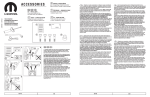
To Move The Unit:
;K|
%
Q
|
"
"
;(
|
#
be moved.
'
|
"""|
9
"
;
|"
8
""
"
"
|3@2
3@@29|4[&[?&;
1. Amoco Oil Co.
2. Cities Service Oil Co.
3. Chevron USA
4. Fina Oil Co.
To Stabilize The Unit:
<'&
6. Mobil Oil Corporation
;8
"
|"
#
"
%8
"
7. Sentinel Lubricants Corp.
8. Shell Oil Corp.
;
Caution:
Rycon Oil No. 32, 46
Citgo AW Hyd. Oil 32, 46
Citgo All Temp. Hyd. Oil
Chevron EP Hyd. Oil 32, 46
Fina AW 32, 46
Fina Automatic Transmission Fluid
0
++
Gulf Harmony 32 AW 32, 46
0$3<4:4<
/
2[@@"2
Sentinel SH-10 Hydraulic Oil
Tellus Hyd. Oil 32, 46
\]*'[4:=
Rando Oil Hd-32, 46
XCell AW 46 (200)
+
10. Union 76
0
"
""
loaded.
Notes:
Routine Maintenance
2. %#%0U
^#$%&'(
%)|:=94@@;
Hydraulic oil.
Raise the Lift and install the Maintenance Safety Bars before beginning
3. BEACON strongly recommends the use of an oil immersion heater
"
"
"
:@2
(A) Monthly Inspections
1. &
+
3]
%
96
;
2. Check for oil leaks. See Trouble Shooting Section and correct as necessary.
3. &
4. &
"
8
as necessary.
<&
6
6
6. &
7. (
8. Check for unusual noise. See Trouble Shooting.
(B) Yearly inspection
Oil in reservoir should be changed at least once a year, or sooner if the oil
"
K
milky.
(C) Winter/Summer Maintenance
&
'x8
""
U
ambient temperatures prevailing in your area.
1. Do Not Use Brake Fluid.
4. In case an oil heater is used on your lift, refer to temperature settings
""
\']
Options, Attachments and Accessories
6"
"
"""
A. Oil Immersion Heater
%""
"9
4<@)
33<Q4@?|4:@xQ3K*Q=@*!;
#$%&'(
""
"
Q
"
"
:@2
"*
"
"
4@@6J6
"
%"
""
"
"
"
=<2
Caution:
Units equipped with an oil immersion heater should not exceed the
following temperature settings:
Grade of Oil
Used
Oil Viscosity
Rating
Max. Allowable Temp. Setting
of Oil Immersion Heater
Some “Tips” to the Operator
ISO-Vg32
3<@6J63@@2
@2
1. %
"
much as possible.
ISO-Vg 46
4<@6J63@@2
33@2
2. Never use the Lift if it is in need of repairs or in the case of a
malfunction.
3. Notify your maintenance personnel in case you notice anything out of
the ordinary, such as binding, odd pump noises, etc.
4. 0
\JK]
1
can permanently damage the motor or pump by doing so.
5. Important:0
"
"
"
6. For proper operation of the unit, make sure ground is level and horizontal.
Oil Viscosity Recommendations
Best performance can be obtained by utilizing ISO-Vg grade 32, 46 oil
3<@|4<@6J63@@29[4|<:6
:@&;/""
"
=@6J693@6;
/""|""""
"
3<@29=<&;
SAE 10 W 30
:@@6J63@@2
3[@2
SAE 40
~<@6J63@@2
3<@2
B. Flashing Red Light
%4:x0&
)
\JK]
"
""
"
stationary during this time. To turn the light off, depress the stop button
C. Warning Bell
%4:x%&
\JK]
\0(]
"
4
*
"
"33@
"
To Stabilize:
Place Dolly Jack Tow Bar at the rear lift plate and raise. Roller
catch automatically releases, lowering the unit onto the base from.
BTAD is now ready for operation.
To Relocate:
Position Dolly Jack Tow Bar under the rear lift plate, raise. The Flipup/Flip down Wheels will automatically lower and lock in mobile
position. Then, place tow bar under front lift plate and move to next
location. Important: Do not load BTAD when in the mobile position
or attempt to move while loaded
Figure 5 Portability Feature
Hydraulic Circuit (see Figure 6)
)
"
\JK]
"9+
"[;
"9+
"4;'"
9+
"3;
"
9+
";
9+
"~;
+
"
"
maintains the desired elevation.
+
\JK]
"
\]\
]
"
returns into the reservoir through the same suction hose.
)
\0(]
90;
!
9+
":;
"
"
9+
"=;
9+
"<;
9
;
Q
speed of the lift. It is preset and cannot be changed.
8
\0(]
|
!
valve poppet. This prevents the oil from returning to the reservoir and the
"
elevation.
There is a Velocity Fuse (Item 8) at the base of each cylinder. In the
"
%
x
2
"
"
sure is reapplied. This safety feature reduces the possibility of accidental
"
Solenoid Valve:
The solenoid valve is of cartridge construction, and is virtually maintenance-free. If there is a faulty operation, check Trouble Shooting Section.
1. J
"
"
the valve.
2. 8
"
""
#
(Do Not Immerse The Coil).
3. +
\@]
4. 8
"
[@|
Hydraulic Reservoir Capacity:
+
8
&
;=U
"
[|[Q:9;
;?U
"
<9;
Instructions for Repacking Hydraulic Cylinders
General points to note:
"
a normal maintenance function.
Weepage is the small amount of oil that accumulates around the piston
rod and gland assembly in normal use. After a period of time the accu"
"
)
occasionally.
)
)
"
"
93Q4|3;
indication of a leak. These symptoms require a seal replacement.
("
out.
Caution:%
"
enemies of hydraulic systems and hence precautions should be taken
"
"
disassembled components.
+
"
"
2
may cause serious damage to seals and machined surfaces.
Procedure:
1. 8
/
6
#23
2. %
/
6
#
\0(]
3<|4@
"
"
3. 6
\]
operation.
4. Remove the cylinder(s) from the unit by removal of the cylinder
92
3<+
"4<4=4~4?;
92
3<+
"43444[;
< Clamp the cylinder assembly in a vise.
6. 2
?
8
seals accordingly.
7. /
"4?92
3<;
"
8. $
92
3<+
"43444[;
9. 8
"
"
"
(
"
92
3<+
"4<;
Electrical Components
"
%
1. Control Box
"
|
"
6
/
6
|4:x%&&
Thermal overload-3 pole.
%
"
|
K"4@?Q4:@Q4~~Q[?@Q:?@x<@Q=@*!
Secondary: 24V,0.100kVA
Fuse in Secondary Circuit-4AMP
Reset-Automatic or Manual.
$
|($/%34<9/6
"6K
#&K
&;
'
#0"
34]3@]<]
+
%
"
"
33<Q4[@x=@*!
4:x@3@@
x%
+
"
"
"
""
Also, change overload protection to the proper value per motor chart (see
;
2. Electric Motor
+
"($
&
9($&;
430-22 and the local codes. For reference, the motor currents are listed
3|3Q4*K4@?Q4[@Q:=@x[K
=@*
![:<@8K/4"
"tent duty, TENV. Super Torque Motor.
VOLTAGE
208
230
460
2&
%"<[:?4:
9;3|3Q4*K33<Q4[@x3K
=*
![:<@8K/4"
"
duty, TENV. Super Torque Motor.
x'%$
33<
4[@
2&
%" 4[
33<
[
"
[
"'
"
""+
"
"
""
2
and 10.
Recommended Motor Lubrication:
&
[9&[;"
Lithium Grease.
Intermittent Duty and
Normal Continuous Duty grease once a year.
High Ambient, moist or dirty
&0
3. Push Button Control Station
\JK]\0(]""
|"
"
one button is depressed the other is mechanically held open.
4. Down Solenoid
06
*
Section uses a 24V, 60Hz coil, requiring 40VA. Removal of coil is accom
"
"
(See Figure 7 for details.)
5. Twist Lock Plug.
3<
"
&"
"
sions for mating receptacles.
Power Supply
208-230V/3PH/60Hz
460V/3PH/60Hz
115V/1PH/60Hz
230V/1PH/60Hz
of Twist Lock Plug
Mating Receptacle (by
(by ECOA)
Purchaser)
3<|4|K
3<|4@8
L16-20P
L16-20R
<|[@K
<|[@8
=|3<K
=|3<8
6. Wiring Diagram.
"
3|3Q4*K4[@xQ3K*Q=@*!
"
"
""
%
#3@%3@#33%0"
*
"
"
0"
7. Wiring Size.
3|3Q4*KK
J
"
|
torque motor. A supertorque motor has the capabilities of producing torque
"
\|
"]
time. Thus, it should be noted that ampere ratings mentioned under
“Electric Motors” is for full load torque. Under actual conditions, the
motors will draw higher current.%
"
!
"
U
(a) 3 Phase Motors:
Voltage
(i) 208-230V
(ii) 460V
(b) 1 Phase Motors:
Voltage
9;33<x
(ii) 230V
Wire Size
3:
34
3:
For Lengths Up to
~<
3<@
3~<
Wire Size
3:
?
=
34
3@
?
for Lengths Up to
~<
?<
130 feet
~<
33<
3~<
Note:
1. 233<xQ3K*Q=@*!K
6
For proper operation, it is necessary to provide a separate 30 AMP circuit
^
!
33<
+"
!
"
"
"
2. 3|3Q4*K
"
^
"/
^
full lift every 4 minutes. This is to avoid overheating of motors. Please
"
\JK]
\0')(]
In high frequency operations or faster speeds consult factory for use of
"
Figure 12 Electrical
Schematic with
208/230/460V/3PH/60Hz
Power Supply for
BTAD Units Fitted with
Optional Flashing Red
Lights.
Figure 13 Electrical
Schematic with
208/230/460V/3PH/60Hz
Power Supply for
BTAD Units Fitted with
Optional Warning Bell.
Figure 14 Electrical
Schematic with
208/230/460V/3PH/60Hz
Power Supply for
BTAD Units Fitted with
Optional Warning Bell
And Flashing Red Light.
Figure 15 - General Layout of BTAD Series
Third Scissor Leg Details
(For Model BTAD-xx-806 ONLY)
(View from Dolly Jack End)
Figure 15 General Layout of BTAD Series
Item
No.
1
2
3
4
<
6
7
8
9
10
11
12
13
14
3<
16
17
18
19
20
21
22
23
24
4<
26
27
28
29
30
31
32
33
34
[<
36
37
38
39
40
41
42
43
44
:<
46
47
48
49
<@
<3
<4
<[
<:
<<
<=
<~
<?
<
60
61
62
63
64
=<
66
67
68
69
70
71
Part
Number
**
**
**
BHLD-P533-30060
BTAD-P5201
HLD-P533-18060
BTAD-P5001
BTAD-P1751
BTAD-P1758
BTAD-P4101-48S
BTAD-P4101-72S
BTAD-P410196S
BTAD-P1401
BHLD-P932
BHLD-P913
BHLT-P950
BHLT-P972
BTAD-P9303
BHLD-P996
BTAD-P9003
BHLT-P970
BHLD-P994
BMS35291-199
BMS35291-119
BMS27183-18
BMS35291-113
BTAD-P9005
BWFC-P108
BMS27183-27
BCYL-A2805-5650
BMS35291-116
BMS35338-48
BMS35690-802
BTAD-P9301
BTAD-P9306
BTAD-P9307
BMS35291-8
BMS35338-44
BMS35690-402
BTAD-P9305
BMS35842-14
BHLT-P971
BCHN-P192-5.67SH
BCHN-P192-7.67SH
BCHN-P192-4.67
BMS35291-36
BMS27183-12
BMS35690-502
BCHN-P192-4.17
BMS35239-119
BMS51922-170
BHLT-P9101
BMS24667-76
BHLT-P320-1
BHLT-P2010
BHLT-P9020
BHLT-P9007
BTAD-P9021
BHLT-P9006
BTAD-P9020
BL-121
BL-132
BL-129
BL-96
BL-155
BL-73
BL-97
BL-140
BHLD-ST-2
L-71
BTAD-P1671
BHLD-P907
BCAS-WA-PY6
BTAD-P9010
BHLT-P953
BDSL-P9064
BHLT-P971
BMS24667-76
Description
#
2"
%
"9
=:;
6
%
"9
=~~3;
Platform Assembly
66
8"%
"[@=@
'%""8"%
"[@=@
66
#
%
"3?=@
'%""#
%
"3?=@
0|69
=<==;
0#9'$^"
;9=<==;
*%
"|::]Q
*%
"|=?]Q
*%
"|4]Q
Safety Maintenance Angles
Rollers
Roller Pins
Bearings
Retaining Rings
Spacers
Spacers
Clevis Pin Weldment
Washers
Lifting Eyes
[Q:J(&<]**/#
3Q4J(&[]**/#
3Q4])
3Q4J(&33Q4**/#
Cylinder Mounting Pin
Retaining Ring
Washer
&
%
"9+
+
"(34<3[=;
3Q4|3[J(&**/#43Q:
3Q4])
3Q4|3[J(&*
(
Cylinder Mounting Plate
Cylinder Gasket
Cylinder Gasket Plate
3Q:|4@J(&**/#3]
3Q:)
3Q:|4@J(&*
(
&
#
9'$^"
';
#
&"9'$^"
';
Washer
6
&=?])Q36|
6
&4])Q36|
8"K
/&<=]
[Q:]|3?J(&33Q:**/#
<Q3=]2)
x
]|3?J(&*
(
#
K
/&<@]
3Q:]|3=J(&33Q:]6
2Q*
[Q:]|3=J(&(|0"
Retaining Washer
2*6
93Q4]|3[J(&33Q4;
Leg Assembly
Leg
Roller
Roller Pin
Roller Pin
Pin
%
K%
"
0
\/
6
#]
0
|K
6
0
\&%J+'(|)+8+(]933<x;
0
|\8
"
6#]
ECOA Logo
0
\0
|]
0
\&]
0
\&|%"#
&
]
#1
6
6
9"44U"4=U;
Name Plate
Transport Roller Assembly (Reference)
%
K98
;
&
%
"|=]0"
K98
;
%
K98
;
Bushing (Reference)
Retainer Washer (Reference)
Flat Washer (Reference)
*
62Q*6
98
;
Qty. Required
BTAD-XX-606
1
1
1
1
1
1
1
1
1
1
2
4
4
16
16
8
4
4
4
4
1
2
1
2
4
4
2
16
16
17
4
2
2
8
8
8
2
2
4
2
2
4
2
2
2
2
4
2
1
3
2
4
2
2
AR
1
2
1
2
2
8
2
4
2
BTAD-XX-608
1
1
1
1
1
1
1
1
1
1
2
4
4
16
16
8
4
4
4
4
1
2
1
3
6
6
3
24
24
4<
6
3
3
12
12
12
3
3
4
2
2
4
2
2
2
2
4
2
1
3
2
4
2
2
AR
1
2
1
2
2
8
2
4
2
BTAD-XX-806
1
1
1
1
1
1
1
1
1
1
2
4
4
23
23
8
4
10
4
4
1
2
1
3
6
6
3
24
24
4<
6
3
3
12
12
12
3
3
3
4
2
2
4
2
2
2
2
1
1
1
1
2
1
1
1
1
4
2
1
3
2
4
2
2
AR
1
2
1
2
2
8
2
4
2
Trans-A-Dok™ Parts List
Quality
Required
19.
HOS-P430-03
HOS-P434-03
BELC-P126-09
20.
BELC-P126-07
21.
22.
23.
24.
BMS35291-6
BMS35338-44
BMS35690-402
BHOS-P107-0340
4<
26.
BHYD-44-02
BELC-P105-10
BELC-P105-15
27.
28.
29.
30.
BELC-P105-14
BELC-P115-12
BELC-P115-11
BELC-P115-09
BELC-P115-10
BELC-P105-14
ELC-P109-01
1
3
3
6
3
2
1
1
3
3
6
3
2
1
1
1
1
1
1
1
1
1
1
1
1
1
1
1
1
1
1
1
1
1
1
1
1
1
1
1
1
1
1
1
1
1
1
1
1
1
1
1
1
1
1
9
9
9
2
1
9
9
9
3
1
9
9
9
3
1
1
1
1
1
1
1
1
1
1
1
1
6
1
1
1
1
1
1
1
6
1
1
1
1
1
1
1
6
1
Part Number
BELC-P105-24
BELC-P107-02
BTAD-P9308
BELC-P105-15
BELC-P105-10
[<
36.
37.
38.
39.
40.
41.
BELC-P105-22
BELC-P105-14
BL-134
BL-133
BL-137
BL-136
BL-135
BELC-P03-5-10-10
BL-132
BELC-P112-04
BELC-P101-06
BELC-P101-07
BELC-P101-08
BELC-P101-03
42.
999-6033
999-6002
43.
999-6004
44.
:<
BL-130
BHLD-P988
46.
BHLT-P709
47.
48.
BHOS-P418-06
BELC-P05-4-14-250
49.
<@
<3
999-6007
999-6006
BELC-P06-16-14
Description
(|3Q4]
Push Button Station
Aluminum Bracket
&
&
[Q:]*
(for 1
0 only)
&
&
[Q:]*
(for 3 0 only)
[Q:](
Cable Connector
0
|:=@xQ[K*Q=@*!
0
|4[@xQ[K*Q=@*!
0
|4@?xQ[K*Q=@*!
0
|4[@xQ3K*Q=@*!
0
|33<xQ3K*Q=@*!
Fork Connector
0
|
6
&&3=|:%)3@U$
K4[@xQ3K*Q=@*!
9=|3<K;
K33<xQ[K*Q=@*!
9<|[@K;
K4@?|4[@xQ[K*Q=@*!
93<|4@K;
K:=@xQ[K*Q=@*!
only (L16-20P)
K
&/
3@%)|[
6'&4?@]
96
K
KQJ;
K
&/
3:|:
6'&4?@]
9[K
KQJ;
6
"6
3=|4\6']&3<U
Decal - Oil
Hose Clip
K"4"[=@@8K/
9
"<:34@34:
138 thru 147)
$
@&
(for single phase capacitor only)
Spring Connector (Red)
6&
91
;
Butt Connector (1 0 only)
Butt Connector (3 0 only)
TAD-XX-806
BHYD-41-03
BHOS-P422-15
BHOS-P350-08-08
BHOS-P404-05
BHOS-P201-08-180
BHOS-P351-08-08
BHYD-43-02
BHOS-P404-05
BHLD-P720
BHOS-P419-01
BHLD-P719
1
2
2
4
2
2
1
TAD-XX-608
8.
9.
10.
11.
12.
13.
14.
3<
16.
17.
18.
Adapter
Velocity Fuse
Adapter
Reducer
2&x
Coupling
*
%
"%(K
44]
Breather Filter
$
Hose Fitting - Straight
(
[Q?(K
6*
3Q4]+Q03?]
$2
Suction Filter
(
[Q:]
2&x
[@K/
$
Solenoid Valve (Ref.)
(Part of Item 83)
[Q:(K
&[Q:(K
$
/33Q4*K
4[@Q33<x3K*Q=@*!
$
/33Q4
*K4@?Q4[@Q:=@x[K*Q=@*!
3Q:|4@J(&**/#[Q:
A 0 LW
3Q:|4@J(&*
(
*
%
"[Q?(K
[:]
Filter
Cable Connector
9[@K
6;
Cable Connector
93@K
6;
3Q4]&
&
[@xQ3K*Q=@*!
!<xQ3K*Q=@*!
@?|4[@xQ[K*Q=@*!
&#:=@xQ[K*Q=@*!
3Q4]&
&
"6
Item
No.
31.
32.
33.
34.
TAD-XX-606
BHOS-P413-37
BHLD-P721
BHOS-P412-02
BHOS-P401-03
BTAD-P7101
BHOS-P402-03
BHOS-P109-0220
Description
TAD-XX-806
1.
2.
3.
4.
<
6.
7.
Part Number
TAD-XX-608
Item
No.
TAD-XX-606
Quality
Required
4
1
1
4
1
1
4
1
1
3
3
3
3
4
1
2
2
2
2
2
6
1
1
1
3
4
1
2
2
2
2
2
6
1
1
1
3
4
1
2
2
2
2
2
6
1
1
1
1
1
1
1
1
1
1
1
1
1
1
1
1
1
1
1
1
1
1
1
1
1
1
1
1
1
1
2
2
3
2
3
2
2
4
2
4
2
4
2
4
2
4
2
4
Item
1.
2.
3.
4.
<
6.
7.
8.
9.
10.
11.
12.
13.
Part Number
&1|84?@[|=[<@
&1|/@@4<|@:3
CYL-M0002-327
CYL-M0007-327
CYL-G0002
CYL-M0006-228
CYL-M0001-228
&1|#[:@<|=3[?
CYL-P0001
MS3217-1137
HYD-31-16
HDW-P9-0406
&1|%4?@3|8
Description
Qty.
1
1
1
2
1
1
1
1
1
1
1
1
1
Piston Rod
Retainer Ring
Quad Ring
Back-Up Rings
Gland
Back-Up Ring
@U8
Barrel Assembly Weldment
Piston
Retaining Ring
06
#*
6
&8
9&
"[:=~3334;
Item
1.
2.
3.
4.
<
6.
7.
8.
9.
10.
11.
Part Number
BHLD-P709-3
BHLT-P709-2
BHLT-P709-1
BHLT-P709-4
#*|K~@|<
BHLT-P709-10
BHLT-P709-11
BHLT-P709-12
BHLT-P709-13
BHLT-709-14
BHLD-P719
12.
13.
14.
3<
16.
BHLD-P719-1
BMS3393-10
BHYD-44-01
CYL-M0001-014
CYL-M0006-014
Description
Cap Valve
6
Relief Valve Compression Spring
Plug
Seal
Check Valve Seat
Check Valve Spring
&
x
6
Check Valve Plug
'U8
24VAC Solenoid Valve Assembly
(Consists of items 12 through 16)
Solenoid Coil - 24VAC
'U8
Pressure Line Filter
'U8
Back up Ring
Qty.
1
1
1
1
1
1
1
1
1
1
2
1
1
1
1
1
Item
No.
1.
2.
3.
4.
<
6.
7.
8.
9.
10.
11.
12.
13.
Part Number
ELC-P119-01
ELC-P118-02
ELC-P118-03
ELC-P118-04
$&|K33?|@<
ELC-P117-01
ELC-P116-01
ELC-P116-02
ELC-P122-01
ELC-P103-06
ELC-P120-01
ELC-P120-04
ELC-P119-01
ELC-P120-02
ELC-P120-04
ELC-P128-01
ELC-P119-01
Description
Terminal Block
"'
33<%/K933<xQ3K*Q=@*!;
"'
4[%/K94[@xQ3K*Q=@*!;
"'
=<%/K94@?|4[@xQ[K*Q=@*!;
"'
43%/K9:=@xQ[K*Q=@*!;
Motor Starter, 24VAC Coil, size 0
Transformer (Prim: 208,230,460V) (Secn: 24VAC)
"
9K"33<Q4[@x;96
4:x%&;
Fuse, Control Circuit, 4AMP
$
($/%3434]3@]<]
@|3@6
%
"
0
8
Base Socket for Relay
Terminal Block
24 VAC Relay
Base Socket for Relays
8
4:x%&Q4:x0&
Terminal Block
Qty.
1
1
1
1
1
1
1
1
1
1
1
3
1
1
1
2
Trouble Shooting
Observation
1.
2.
3.
Lift does not raise but pump is running or
humming.
/
Possible Cause
Remedy
a.
Motor rotation may be reversed.
a.
6
"
tion. Change motor rotation per notes in
Electrical Section. If Lift has been running
properly for some time, then it is possible
"
b.
Motor may be single phasing. (humming)
b.
&
ascertain that all 3 phase lines are present
at the motor.
c.
"
""
"
c.
Measure voltage at motor terminals, or as
"
+
^
starve the motor. Correct as necessary.
d.
Hose or hydraulic line is leaking.
d.
Correct as necessary.
e.
'
e.
Add oil
f.
^
"
8
valve is bypassing the oil back into the
tank.
f.
Do not change Relief Valve setting. Instead,
reduce the load to rated capacity.
g.
6
"
g.
Remove and clean.
h.
Suction line may be leaking air due to loose
h.
&
i.
2
Q#
"
i.
Remove and clean.
0x
"
!
Remove Solenoid Valve, check and clean.
(See Hydraulic Section.)
k.
Hydraulic pump may be inoperative.
k.
0
K
hose end in a large container and run pump
again. If no output, check motor rotation as
per 1(a) above. Check also, the pump""
+"
"
a.
2
"
06
causing some oil to bypass back into tank.
a.
8
"
6
x
and clean it. (See Hydraulic Section.)
b.
2
"
pinched hose.
b.
Correct as necessary. (See also 1(g), (i).)
c.
/
c.
See 1(c).
d.
Lift overloaded.
d.
See 1(f).
e.
Oil is too thick for proper operation.
e.
8
\'x8
""
]
f.
f.
Cylinder may be binding. Align correctly.
g.
Pump is inoperative
g.
See 1(k).
a.
x
"
a.
8
"
6
x
and clean it. (See Hydraulic Section.)
b.
+
b.
Correct as necessary. (See also 1(g), (i).)
c.
Oil starvation causes pump to bind. High
internal heat is developed if this occurs,
pump may be permanently damaged.
c.
See 1(c).
d.
Binding cylinders.
d.
See 1(f).
e.
Oil may be too thick.
e.
8
\'x8
""
]
Trouble Shooting
Observation
4.
<
6.
7.
8.
\6]\
]
0
Air trapped in cylinders. confuse spongy op
"
"
^
Possible Cause
Remedy
a.
Air trapped cylinders.
a.
#
\0(]4@|[@
"
Raise Lift and repeat procedure several
times. Bleed cylinders also, by loosening
"
comes out.
b.
Oil starvation.
b.
See 1(e), (g), (h), (i)
a.
0x
a.
8
"
6
x
b.
Pinched tube or hose.
b.
Correct as necessary. (In case of pipe,
check for obstruction in line.)
c.
Oil too thick.
c.
6
\'x8
""
]
your ambient temperatures.
d.
2
"
2&x
d.
"
2&x
and clean. (See Hydraulic Section.)
e.
Binding cylinders.
e.
See 2(f).
f.
Foreign material in Velocity Fuse.
f.
Remove and clean.
a.
a.
Correct as necessary.
b.
Check valve stuck open. (The combination
of a stuck Check Valve and open Solenoid
x
b.
Remove Check Valve and clean it. (See
Hydraulic Section)
c.
2
"
2&
x
9+
normal rate then speeds up as the platform
descends.)
c.
8
"
2&x
a.
06
x
"
a.
See 2(a).
b.
Check Valve may be stuck open.
b.
Remove and clean. (See Hydraulic Section.)
c.
&
c.
Correct as necessary.
d.
&
"
"aged.
d.
Replace packings. (See Cylinder Repair
procedure.)
a.
#
a.
Check and replace.
b.
+
06
x
b.
Correct as necessary. (See Wiring Diagram.)
c.
06
x
c.
6
&
seat it properly. (Do not hit hard as it will
permanently damage the internal stem.)
Do not remove the Solenoid Valve from
the Pump Body as the unit will come
down at a dangerous speed.
d.
206
&
d.
Remove and replace.
e.
Maintenance safety bar, or some other
e.
Raise Lift and remove the safety bar, or
f.
Binding cylinders.
f.
See 2(f).
g.
+
x
2
"
"
"
"
g.
To unlock, repressurize the hydraulic
system.
h.
$IFDLJGUIF-JNJU4XJUDIJTJOPQFSBUJWFBOEUIF
QMBUGPSNIBTSBJTFEBMMUIFXBZTPUIBUUIFJOUFS
OBMDZMJOEFSTUPQTBSFJOPQFSBUJPO*GTUPQTBSF
JOPQFSBUJPOWFMPDJUZGVTFTIBWFCFFOMPDLFEVQ
h.
Put maintenance safety bar in place and
#
9+
"3[=?;"
the cylinder. After the platform drops by a
"6
"=@]8
*