1
Page 1
Operation Manual for
Automatic Leveling Systems
with Touch Pad # 140-1226
and Control Box # 140-1229
c Copyright PowerGear 11/05 #82-L0379 Rev. 0B
O
Operation Manual for
Automatic Leveling Systems
with Touch Pad
# 140-1226
and Control Box
# 140-1229
Power Gear Electronic Leveling
MANUAL
FRONT
WAIT
JACKS DOWN
LOW VOLTAGE
ENGAGE PARK BRAKE
CAUTION
Contents
Before you Level Your Coach
1
Operating Instructions
2
Retracting your Leveling Jacks
2
Manually Operating your Jacks
3
Preventive Maintenance
4
Troubleshooting Tips
5
Manual Override Valves
6
Warranty Informtion
7
ON
OFF
AUTO
LEFT
Level
REAR
RIGHT
ALL
JACKS
Read and understand operators manual before using.
Do not use jacks for tire removal or under vehicle service.
Before You Level Your Coach
1. Park brake must be set and transmission must be in “park” (“neutral” for diesel
coaches) before jacks will operate.
2. Check leveling site to make sure obstructions have been cleared away for proper
jack operation.
3. Selecting a site: When the coach is parked on an excessive slope the leveling
requirements may exceed the jack lift stroke capability. If the coach is parked on
an excessive slope, the coach should be moved to a more level surface before the
leveling system is deployed.
• Keep people clear of coach prior to turning the leveling system on and while leveling
system is in use.
• Never expose hands or other parts of the body near hydraulic leaks. High-pressure
oil leaks may cut and penetrate the skin causing serious injury.
,I\RXUFRDFKLVHTXLSSHGZLWKDVOLGHRXWVDOZD\VOHYHO\RXUXQLW¿UVWDQGWKHQRSerate the slide out room(s). When retracting the slide(s), always retract the room(s)
¿UVWWKHQUHWUDFWWKHOHYHOLQJMDFNV)ROORZLQJWKLVSURFHGXUHZLOOSURGXFHWKHOHDVW
amount of stress on your chassis.
• Please read the owners’ manual from the manufacturer who built and designed your
motor home for further leveling and slide out room operating information and safety
features.
Power Gear
1217 E. 7th Street
Mishawaka, IN 46544
800/334-4712
www.powergearus.com
This is a leveling system only and is not intended to lift your coach’s tire or tires completely off the ground. Attempting to lift your coach completely off the ground (for example, to use this leveling system to change a tire) could cause damage to the system
and serious injury to the parties involved. If a tire should require changing please have
the proper equipment and contact a professional.
Page 2
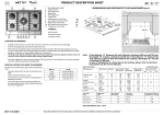
Operating Instructions
Automatic
mode button
Front jacks
button
Power Gear Electronic Leveling
MANUAL
Manual operation
button (push and
hold for 5-7
seconds)
ON
OFF
AUTO
FRONT
WAIT
LEFT
JACKS DOWN
LOW VOLTAGE
ENGAGE PARK BRAKE
CAUTION
Level
REAR
Right jacks
button
RIGHT
ALL
JACKS
Read and understand operators manual before using.
Do not use jacks for tire removal or under vehicle service.
Left jacks
button
Rear jacks
button
Leveling Your Coach
1. Turn on the ignition and start the coach. Your leveling control will start a self check sequence indicated by the lights
RQWKHSDQHOEOLQNLQJLQDURWDWLQJSDWWHUQ,WZLOOWXUQRIIZKHQLWKDV¿QLVKHGLW¶VVHOIFKHFN
2. Push the “On/Off” button on control panel. The system is now operational and the “On/Off” LED will turn on.
3. Check to see that the engage park brake light is not illuminated. If so, engage the parking brake. (Your coach will
have to be in neutral or park to operate the system).
4. Push the “AUTO” button. The automatic leveling system will begin it’s leveling procedure. Please avoid movement
in the coach during automatic leveling as it can cause errors in the results. It will signal that it has completed the
process by illuminating the center green “Power Gear LEVEL” light. Check to make sure that all jacks are on the
ground. Also check to make sure that no tire is off the ground. If so, your leveling process is complete. If further
adjustments are needed, refer to the “Manual Operation” section.
5. You can then turn the system off by pushing the on/off button again.
Retracting Your Leveling Jacks
1. Turn on the ignition
2. Turn on the system by pushing the “on/off” button. The system is now operational and the “On/Off” LED will turn on.
3. Push the “RETRACT-ALL JACKS” button. When the “JACKS DOWN” light turns off, visually check to make sure that
all jacks have fully retracted. If so, your coach leveling system is ready to travel.
Page 3
Manually Operating Your Leveling Jacks
There are certain conditions where manually leveling your coach may be desirable. Conditions where large amounts of
side to side leveling are necessary may work better using the manual leveling procedures that follow.
1. Turn on the ignition and start the coach.
2. Push the “On/Off” button to turn on the system.
3. Push and hold the “MAN” button for 5-7 seconds in order for the system to switch to the manual mode. It will signal
that it is in the manual mode when the light under the “MAN” button is illuminated.
3XVK³)5217´EXWWRQXQWLOWKHIURQWRIWKHFRDFKULVHVDWOHDVW´7KLVLVLPSRUWDQWDQGQHFHVVDU\WRDOORZWKHFRDFK
WRSLYRWZKHQOHYHOLQJVLGHWRVLGH,IWKHUHLVLQVXI¿FLHQWMDFNVWURNHWROLIWWKHIURQWRIWKHFRDFKDWOHDVWLQFKHVWKH
coach will have to be moved to an area with less front to back slope, or a weight distribution block will have to be
placed under the jack.
5. Push the “REAR” button until jacks contact the ground.
6. Level the coach from front to rear by pushing the “REAR” button if the
NOTE: The right and left rear jacks are
light under the “REAR” button is illuminated. If the light is illuminated
used to level the coach side to side.
DERYHWKH³)5217-$&.6´EXWWRQSXVKWKH³)5217´EXWWRQ,QHLPushing the “LEFT” button on the conther case, keep button depressed until the green center “LEVEL” light is
trol panel will extend left rear jack. Pushilluminated, or both front and rear lights are dark.
ing the “RIGHT” button on the control
panel will extend right rear jack.
7. Level the coach from side to side by pushing the “RIGHT” button if the
light beside the “RIGHT” button is illuminated. If the light beside the
³/()7´EXWWRQLVLOOXPLQDWHGSXVKWKH³/()7´EXWWRQXQWLOWKH³/(9(/´
light is illuminated.
8. Repeat steps 6 and 7 if needed.
7XUQSRZHURIIWROHYHOLQJV\VWHPE\SXVKLQJ³212))´EXWWRQ
10. Visually inspect jacks to ensure all pads are touching ground. Should
127(,IWKH³:DLW´/('LVHYHUÀDVKone of the rear jacks not be touching the ground, press the corresponding by itself, it means the control is
ing left or right rear jack buttons to lower the appropriate jack to the
busy and you cannot operate the jacks.
ground. Never lift the wheels off the ground to level the coach. This
After a short period of time (from 5 to
can lead to an unsafe condition and damage to the leveling system or
30 seconds), the “Wait” LED will go off
again, and you can resume operation as
coach.
normal.
Page 4
Preventative Maintenance
&KHFNDQGRU¿OOWKHUHVHUYRLUZLWKWKHMDFNVDQGURRPVLQWKHIXOO\UHWUDFWHGSRVLWLRQHDFKPRQWK7KHÀXLGVKRXOGEHRQHLQFKRQWRWKHGLSVWLFN
RQPRGHOVVRHTXLSSHGRUWRWKHERWWRPRIWKH¿OOSRUWRQPRGHOVZLWKRXW
dipsticks.
&KDQJHÀXLGHYHU\PRQWKV
Your coach should be supported at both
3. Inspect and clean all hydraulic pump electrical connections every 12
front and rear axles with mechanical jack
months.
stands, not Power Gear hydraulic jacks,
EHIRUHZRUNLQJXQGHUQHDWK)DLOXUHWRGRVR
4. Remove dirt and road debris from jacks as needed.
may result in personal injury or death.
5. If jacks are down for extended periods, it is recommended to spray exposed leveling jack chrome rods with a silicone lubricant every 5 to 7 days
for protection.
6. If your coach is located in a salty environment (within 60 miles of coastal areas), it is recommended to spray the rods
every 2 to 3 days with a silicone lubricant.
*UHDVHWKH¿WWLQJRQWKHERWWRPRIHDFKMDFNF\OLQGHUZLWK/LWKLXPJUHDVHHYHU\XVHV
Recommended Hydraulic Fluids for Your Hydraulic Pump
7KHÀXLGVOLVWHGKHUHDUHDFFHSWDEOHWRXVHLQ\RXUSXPSDVVHPEO\&RQWDFWFRDFKPDQXIDFWXUHURUVHOOLQJGHDOHUIRULQIRUPDWLRQDERXWZKDWVSHFL¿FÀXLGZDVLQVWDOOHGLQ\RXUV\VWHP
,WLVQRWUHFRPPHQGHGWKDWK\GUDXOLFÀXLGDQGDXWRPDWLFWUDQVPLVVLRQÀXLGVEHPL[HGLQWKHUHVHUYRLU
,QPRVWDSSOLFDWLRQV7\SH$DXWRPDWLFWUDQVPLVVLRQÀXLG$7)'H[URQ,,,HWFZLOOZRUNVDWLVIDFWRULO\0HUFRQ9LV
DOVRUHFRPPHQGHGDVDQDOWHUQDWLYHÀXLGIRU3RZHU*HDUK\GUDXOLFV\VWHPV
,IRSHUDWLQJLQFROGWHPSHUDWXUHVOHVVWKDQ)WKHMDFNVPD\H[WHQGDQGUHWUDFWVORZO\
)RUFROGZHDWKHURSHUDWLRQÀXLGVSHFLDOO\IRUPXODWHGIRUORZWHPSHUDWXUHVPD\EHGHVLUDEOH0RELO'7(07H[DFR
5DQGR+'=+9,.HQGDOO+\GHQ*ODFLDO%OXRUDQ\0LO6SHF+K\GUDXOLFÀXLGVDUHUHFRPPHQGHGIRUFROG
weather operation.
3OHDVHFRQVXOWIDFWRU\EHIRUHXVLQJDQ\RWKHUÀXLGVWKDQWKRVHVSHFL¿HGKHUH
Page 5
Troubleshooting Tips
/RFDWLRQVRIEUHDNHUVIXVHVIXVHSDQHOVHWFHWHUDDUHFRDFKVSHFL¿F&RQVXOW\RXUFRDFKRZQHU¶VPDQXDORUWKHFRDFK
manufacture for locations of these components.
7KHIROORZLQJLQIRUPDWLRQZLOOJXLGH\RXWRUHSDLUVWKDWPD\EHPDGHRQVLWH)RUSUREOHPVQRWFRYHUHGKHUHFRQWDFW\RXU
service center or our website for more extensive troubleshooting information in the service manual for your system.
System will not turn on, indicator light does not light
Probable Cause
Corrective Action
Coach ignition not in run position.
Turn ignition to run position.
Transmission not in park or neutral.
Place transmission in park or neutral.
Parking brake not set.
Set brake.
Control has been left on for more than four
minutes, auto shut off.
Push on/off button twice.
Jacks will not extend, pump is not running
Probable Cause
Corrective Action
Battery voltage is low.
Recharge battery.
Jacks will not extend, pump is running
Probable Cause
Corrective Action
)OXLGOHYHOORZ
)LOOWDQNWRSURSHUOHYHOZLWKDXWRPDWLFWUDQVPLVVLRQÀXLGVHHWLSVKHHW
All jacks will not retract or will not retract fully
Probable Cause
Corrective Action
6\VWHPRYHU¿OOHGZLWKÀXLG
'UDLQÀXLGWRUHFRPPHQGHGOHYHOVHHWLS
Any one or two jacks will not retract at all
Probable Cause
Corrective Action
Jack rod guide is rusted or dirty.
&OHDQFKURPHURGJUHDVHURGJXLGHLIHTXLSSHGZLWKJUHDVH¿WWLQJV2WKHUZLVHOXEULFDWHZLWKVLOLFRQHÀXLG,WPD\EHQHFHVVDU\WRUHVHDOMDFNRUUHSODFH
Any jack retracts very slowly
Probable Cause
Corrective Action
Jack rod guide is rusted or dirty.
&OHDQFKURPHURGJUHDVHURGJXLGHLIHTXLSSHGZLWKJUHDVH¿WWLQJV2WKHUZLVHOXEULFDWHZLWKVLOLFRQHÀXLG,WPD\EHQHFHVVDU\WRUHVHDOMDFNRUUHSODFH
Any jack retracts with no power, with possible popping sound
Probable Cause
Corrective Action
Air in system.
Check for coils in hose. Remove the coil if present then extend all jacks to full extension, then retract fully, repeat 4 cycles waiting a few minutes between cycles, check
ÀXLGOHYHOLQEHWZHHQF\FOHV
&RQWDPLQDWHGÀXLG
5HSODFHÀXLGVHHSDJHWLSVKHHWDQG
Jack legs create popping sound.
Extend jack legs, clean rod, lubricate with light weight grease if equipped with grease
¿WWLQJVRUOXEULFDWHZLWKVLOLFRQHVSUD\
'XHWRFKDQJHVLQWHPSHUDWXUHH[SDQGLQJDQGFRQWUDFWLQJRIÀXLGZLOOPDJQLI\WKH
SUREOHPRISRSSLQJMDFNVWRKHOSPLQLPL]HWKLVUHSODFHÀXLGZLWK0HUFRQ9ÀXLG
Panel jacks down light illuminated, buzzer is on- jacks are retracted
Probable Cause
Corrective Action
/RZÀXLGOHYHO
)LOOWDQNZLWK'H[URQ,,,DXWRPDWLFWUDQVPLVVLRQÀXLGVHHWLSVKHHW
Panel jacks down light and alarm will go on while driving, jacks retracted
Probable Cause
Corrective Action
/RZÀXLGOHYHO
)LOOWDQNZLWK'H[URQ,,,DXWRPDWLFWUDQVPLVVLRQÀXLGVHHWLSVKHHW
Page 6
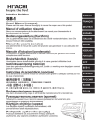
Manual Override Valves
In case of a loss of power at the pump assembly, the manual override valves (MOV’s)can be used to retract the leveling
jacks. Not all Power Gear leveling system pumps have manual override valves. Power units for double acting systems
WKDWKDYHPDQXDORYHUULGHYDOYHVKDYHÀH[LEOHUXEEHUFDSVRQWKHYDOYHVDQGDKH[RYHUULGHQXWXQGHUWKHEXWWRQFDSRQ
the electric motor.
To use the MOV’s:
5HPRYHWKHEXWWRQFDSIURPWKHHQGRIWKHHOHFWULFPRWRU)LUVWUHPRYHWKHWZR3KLOOLSVKHDGVFUHZVIURPWKHWRSRI
the motor. The button cap can now be removed from the electric motor. You should now see a 7/16” over ride nut on
the end of the electric motor shaft.
2. After verifying all personnel and tools are clear of the coach, press the
rubber cap on the valve for the front legs valve. The front end of the coach
will start to descend. Only allow the coach to descend for 2 inches.
3. Push and hold the rubber cap on the Roadside Rear valve. Allow the
coach to descend for 2 inches.
4. Push and hold the rubber cap on the Curbside Rear valve. Allow the coach
to descend for 2 inches.
5. Repeat procedures 2-4 until the weight of the coach is transferred off the
jacks and onto the suspension and tires.
Roadside Rear
Leg Valve
Care must be taken during the
manual retraction of jacks to prevent bodily injury or death. The
QH[WVWHSZLOODOORZÀXLGWRWUDQVfer from the legs to the reservoir.
This procedure will allow the
coach to descend. Keep all personnel and equipment clear of the
coach. Make sure no one is under the coach prior to this procedure. Do not have any body parts
or equipment positioned such that
the coach will descend on it.
Curbside Rear
Leg Valve
Front Legs
Valve
Screws
Button Cap
6. This procedure will retract the front legs. Using a 7/16” socket attached to a drill, spin the override nut clockwise
while holding the button on the front legs valve. Stop when the legs are fully retracted.
7. This procedure will retract the roadside rear leg. After the front legs are retracted, press the button on the roadside
rear leg valve and spin the override nut clockwise. Stop when the leg is fully retracted.
8. This procedure will retract the curbside rear leg. After the front legs are retracted, press the button on the curbside
rear leg valve and spin the override nut clockwise. Stop when the leg is fully retracted.
9. Replace the button cap on the electric motor and securely tighten the Phillips head screws.
Page 7
Power Gear Limited Warranty
Power Gear warrants to the original retail purchaser that the product will be free from defects in material and workmanship
for a period of (2) years following the retail sales date. Power Gear will, at its option, repair or replace any part covered
by this limited warranty which, following examination by Power Gear or its authorized distributors or dealers, is found to be
defective under normal use and service. No claims under this warranty will be valid unless Power Gear or its authorized
GLVWULEXWRURUGHDOHULVQRWL¿HGLQZULWLQJRIVXFKFODLPSULRUWRWKHH[SLUDWLRQRIWKHZDUUDQW\SHULRG:DUUDQW\LVWUDQVIHUable pending documentation of original sale date of product.
THIS WARRANTY SHALL NOT APPLY TO:
)DLOXUHGXHWRQRUPDOZHDUDQGWHDUDFFLGHQWPLVXVHDEXVHRUQHJOLJHQFH
3URGXFWVZKLFKDUHPRGL¿HGRUDOWHUHGLQDPDQQHUQRWDXWKRUL]HGE\3RZHU*HDULQZULWLQJ
)DLOXUHGXHWRPLVDSSOLFDWLRQRISURGXFW
• Telephone or other communication expenses.
• Living or travel expenses.
• Overtime labor.
)DLOXUHVFUHDWHGE\LPSURSHULQVWDOODWLRQRIWKHSURGXFW¶VVOLGHRXWV\VWHPRUVOLGHRXWURRPWRLQFOXGH¿QDODGMXVWPHQWV
made at the plant for proper room extension/retraction; sealing interface between slide out rooms and side walls; synchronization of inner rails; or improper wiring or ground problems.
)DLOXUHVFUHDWHGE\LPSURSHULQVWDOODWLRQRIOHYHOLQJV\VWHPVLQFOXGLQJ¿QDODGMXVWPHQWVPDGHDWWKHSODQWRUORZÀXLG
level, wiring or ground problems.
• Replacement of normal maintenance items.
7KHUHLVQRRWKHUH[SUHVVZDUUDQW\RWKHUWKDQWKHIRUHJRLQJZDUUDQW\7+(5($5(12,03/,(':$55$17,(62)
0(5&+$17$%,/,7<25),71(66)25$3$57,&8/$5385326(,112(9(176+$//32:(5*($5%(/,$%/(
)25$1<,1&,'(17$/25&216(48(17,$/'$0$*(67KLVZDUUDQW\JLYHV\RXVSHFL¿FOHJDOULJKWVDQG\RXPD\
also have other rights, which vary from state to state. Some states do not allow the limitations of implied warranties, or
the exclusion of incidental or consequential damages, so the above limitations and exclusions may not apply to you.
)RUVHUYLFHFRQWDFW\RXUQHDUHVW3RZHU*HDUDXWKRUL]HGZDUUDQW\VHUYLFHIDFLOLW\RUFDOO:DUUDQW\VHUYLFH
can be performed only by a Power Gear authorized service facility. This warranty will not apply to service at any other
facility. At the time of requesting warranty service, evidence of original purchase date must be presented.
Page 8
Power Gear
1217 E. 7th Street
Mishawaka, IN 46544
800/334-4712
www.powergearus.com