1
$0'
$0'
&203$&70,;(56
$0'
(QJOLVK
,03257$176$)(7<,16758&7,216
7KHDSSDUDWXVVKDOOQRWEHH[SRVHGWRGULSSLQJRUVSODVKLQJDQGWKDWQRREMHFWV¿OOHGZLWKOLTXLGVVXFKDVYDVHV
VKDOOEHSODFHGRQWKHDSSDUDWXV7KH0$,16SOXJLVXVHGDVWKHGLVFRQQHFWGHYLFHWKHGLVFRQQHFWGHYLFHVKDOO
UHPDLQUHDGLO\RSHUDEOH
:DUQLQJWKHXVHUVKDOOQRWSODFHWKLVDSSDUDWXVLQWKHFRQ¿QHGDUHDGXULQJWKHRSHUDWLRQVRWKDWWKHPDLQVVZLWFK
FDQEHHDVLO\DFFHVVLEOH
5HDG WKHVH LQVWUXFWLRQV EHIRUH RSHUDWLQJ WKLV
DSSDUDWXV
.HHSWKHVHLQVWUXFWLRQVIRUIXWXUHUHIHUHQFH
&$87,21
5,6.2)(/(&75,&6+2&.
'212723(1
+HHGDOOZDUQLQJVWRHQVXUHVDIHRSHUDWLRQ
)ROORZDOOLQVWUXFWLRQVSURYLGHGLQWKLVGRFXPHQW
'RQRWXVHWKLVDSSDUDWXVQHDUZDWHURULQORFDWLRQV
ZKHUHFRQGHQVDWLRQPD\RFFXU
&OHDQRQO\ZLWKGU\FORWK'RQRWXVHDHURVRORUOLTXLG
FOHDQHUV8QSOXJWKLVDSSDUDWXVEHIRUHFOHDQLQJ
'RQRWEORFNDQ\RIWKHYHQWLODWLRQRSHQLQJV,QVWDOO
LQDFFRUGDQFHZLWKWKHPDQXIDFWXUHU¶VLQVWUXFWLRQV
&$87,21725('8&(7+(5,6.2)(/(&75,&6+2&.
'21275(029(&29(525%$&.
1286(56(59,&($%/(3$576,16,'(
5()(56(59,&,1*7248$/,),('3(56211(/
7KH OLJKWQLQJ IODVK ZLWK DUURZKHDG V\PERO ZLWKLQ DQ
HTXLODWHUDO WULDQJOH LV LQWHQGHG WR DOHUW WKH XVHU WR WKH
SUHVHQFH RI XQLQVXODWHG ³GDQJHURXV YROWDJH´ ZLWKLQ WKH
SURGXFW¶VHQFORVXUHWKDWPD\EHRIVXI¿FLHQW
'RQRWLQVWDOOQHDUDQ\KHDWVRXUFHVVXFKDVUDGLDWRUV
KHDWUHJLVWHUVVWRYHVRURWKHUDSSDUDWXVLQFOXGLQJ
DPSOL¿HUVWKDWSURGXFHKHDW
'RQRWGHIHDWWKHVDIHW\SXUSRVHRIWKHSRODUL]HGRU
JURXQGLQJW\SHSOXJ$SRODUL]HGSOXJKDVWZREODGHV
ZLWKRQHZLGHUWKDQWKHRWKHU$JURXQGLQJW\SHSOXJ
KDVWZREODGHVDQGDWKLUGJURXQGLQJSURQJ7KHZLGH
EODGHRUWKHWKLUGSURQJLVSURYLGHGIRU\RXUVDIHW\,I
WKHSURYLGHGSOXJGRHVQRW¿WLQWR\RXURXWOHWFRQVXOW
DQHOHFWULFLDQIRUUHSODFHPHQWRIWKHREVROHWHRXWOHW
3URWHFW WKH SRZHU FRUG IURP EHLQJ ZDONHG RQ RU
SLQFKHGSDUWLFXODUO\DWSOXJFRQYHQLHQFHUHFHSWDFOHV
DQGWKHSRLQWZKHUHWKH\H[LWIURPWKHDSSDUDWXV
2QO\ XVH DWWDFKPHQWVDFFHVVRULHV VSHFL¿HG E\ WKH
PDQXIDFWXUHU
8VH RQO\ ZLWK D FDUW VWDQG WULSRG EUDFNHW RU
WDEOH VSHFL¿HG E\ WKH PDQXIDFWXUHU RU VROG ZLWK
WKH DSSDUDWXV :KHQ D FDUW LV XVHG XVH FDXWLRQ
ZKHQ PRYLQJ WKH FDUWDSSDUDWXV
FRPELQDWLRQ WR DYRLG LQMXU\ IURP WLS
RYHU
8QSOXJWKLVDSSDUDWXVGXULQJOLJKWLQJ
VWRUPV RU ZKHQ XQXVHG IRU ORQJ
SHULRGVRIWLPH
5HIHU DOO VHUYLFLQJ WR TXDOL¿HG VHUYLFH SHUVRQQHO
6HUYLFLQJLVUHTXLUHGZKHQWKHDSSDUDWXVKDVEHHQ
GDPDJHGLQDQ\ZD\VXFKDVSRZHUVXSSO\FRUGRU
SOXJLVGDPDJHGOLTXLGKDVEHHQVSLOOHGRUREMHFWV
KDYH IDOOHQ LQWR WKH DSSDUDWXV WKH DSSDUDWXV KDV
EHHQH[SRVHGWRUDLQRUPRLVWXUHGRHVQRWRSHUDWH
QRUPDOO\RUKDVEHHQGURSSHG
PDJQLWXGHWRFRQVWLWXWHDULVNRIHOHFWULFVKRFNWRSHUVRQV
7KH H[FODPDWLRQ SRLQW ZLWKLQ DQ HTXLODWHUDO WULDQJOH LV LQ
WHQGHGWRDOHUWWKHXVHUWRWKHSUHVHQFHRILPSRUWDQWRSHUDW
LQJDQGPDLQWHQDQFHVHUYLFLQJLQVWUXFWLRQVLQWKHOLWHUDWXUH
DFFRPSDQ\LQJWKHDSSOLDQFH
:$51,1*7RUHGXFHWKHULVNRI¿UHRUHOHFWULFVKRFNGR
QRWH[SRVHWKLVDSSDUDWXVWRUDLQRUPRLVWXUH
&$87,218VHRIFRQWUROVRUDGMXVWPHQWVRUSHUIRUPDQFH
RI SURFHGXUHV RWKHU WKDQ WKRVH VSHFL¿HG PD\ UHVXOW LQ
KD]DUGRXVUDGLDWLRQH[SRVXUH
AM442D/642D
Compact Mixers
TABLE OF CONTENTS
INTRODUCTION....................................................................................................4
FEATURES...........................................................................................................4
GETTING STARTED ..............................................................................................5
CHANNEL SETUP .................................................................................................5
MAKING CONNECTIONS........................................................................................6
Inputs and Outputs .............................................................................................6
Rear Panel .......................................................................................................7
CONTROLS AND SETTINGS ...................................................................................8
Rear Panel ........................................................................................................8
Channel Controls.............................................................................................8
Digital Effect Processor.........................................................................................9
Master Section .................................................................................................10
APPLICATION.....................................................................................................13
DIGITAL EFFECT TABLE........................................................................................15
SPECIFICATIONS................................................................................................16
DIMENSIONS......................................................................................................18
BLOCK DIAGRAMS...............................................................................................19
Phonic reserves the right to improve or alter any information suppied within this document without prior notice.
V1.0 APR 14, 2006
Introduction
Features
Thank you for choosing one of Phonic’s many quality
compact mixers. The brand new AM 442D and AM
642D Mixers – designed by the ingenious engineers
that have created a variety of mixers fantastic in
style and performance in the past – display similar
proficiency that previous Phonic products have
VKRZQZLWKPRUHWKDQDIHZUH¿QHPHQWVRIFRXUVH
)HDWXULQJIXOOJDLQUDQJHVDPD]LQJO\ORZGLVWRUWLRQ
OHYHOV DQG LQFUHGLEO\ ZLGH G\QDPLF UDQJHV WKHVH
DPD]LQJPL[HUVDUHERXQGWRPDNHDELJVSODVKLQ
the world of mixing.
Common Features:
z Audiophile-quality & ultra low noise
z 4 stereo channels with 4-band EQ
z 3-band EQ with swept mid-range plus low cut
on each mono channel
z 32/40-bit digital stereo multi-effect processor with
100+ tap delay plus foot switch
z 2 true subgroups with main L and R routing
switches
We know how eager you are to get started – wanting
to get the mixer out and hook it all up is probably your
QXPEHURQHSULRULW\ULJKWQRZ±EXWEHIRUH\RXGRZH
strongly urge you to take a look through this manual.
,QVLGH\RXZLOO¿QGLPSRUWDQWIDFWVDQG¿JXUHVRQWKH
VHWXSXVHDQGDSSOLFDWLRQVRI\RXUEUDQGQHZPL[HU
If you do happen to be one of the many people who
ÀDWO\UHIXVHWRUHDGXVHUPDQXDOVWKHQZHMXVWXUJH
you to at least glance at the Instant Setup section.
After glancing at or reading through the manual (we
DSSODXG\RXLI\RXGRUHDGWKHHQWLUHPDQXDOSOHDVH
VWRUHLWLQDSODFHWKDWLVHDV\IRU\RXWR¿QGEHFDXVH
FKDQFHVDUHWKHUH¶VVRPHWKLQJ\RXPLVVHGWKH¿UVW
time around.
z 2 stereo aux returns with effect to monitor level
control
z Solo feature on each input and output
z XLR connectors available on main L / R output
z Built-in switching power supply with universal
FRQQHFWRU9$&+]
z Rack-mounting kit included
AM442D also features:
z 4 Mic/Line channels with inserts and phantom
power
z $X[VHQGV$X[ZLWK3UH3RVWVZLWFK
AM642D also features:
z 6 Mic/Line channels with inserts and phantom
power
z $X[VHQGVRQHZLWK3UH3RVWVZLWFK
z 6WHUHREDQGJUDSKLF(4DVVLJQDEOHWRPDLQ
mix or aux 1 send
4
AM442D/642D
Getting Started
Channel Setup
1. Ensure all power is turned off on your mixer. To
WRWDOO\HQVXUHWKLVWKH$&FDEOHVKRXOGQRWEH
connected to the unit.
1. To ensure the correct audio level of the
LQSXW FKDQQHO LV VHOHFWHG HDFK RI WKH 0L[HU¶V
&KDQQHO¶V 21 EXWWRQV VKRXOG EH GLVHQJDJHG
(which should turn the corresponding LED
LQGLFDWRURII±RWKHUZLVHJREDFNDQGWU\DJDLQ
DVZHOODVWKH62/2EXWWRQVRQHDFKFKDQQHO
DQGPDNHVXUHWKDWWKH7571NQRELVDOOWKH
way down.
2. All faders and level controls should be set at
the lowest level and all channels switched off to
ensure no sound is inadvertently sent through
the outputs when the device is switched on. All
levels can be altered to acceptable degrees after
the device is turned on.
3. Plug all necessary instruments and equipment
into the device’s various inputs as required.
7KLV PD\ LQFOXGH OLQH VLJQDO GHYLFHV VXFK DV
NH\ERDUGV DQG GUXP PDFKLQHV DV ZHOO DV
PLFURSKRQHVDQGRUJXLWDUVNH\ERDUGVHWF
4. Plug any necessary equipment into the device’s
YDULRXVRXWSXWV7KLVFRXOGLQFOXGHDPSOL¿HUVDQG
VSHDNHUV PRQLWRUV VLJQDO SURFHVVRUV DQGRU
recording devices.
3OXJWKHVXSSOLHG$&FDEOHLQWRWKH$&LQOHWRQ
the back of the device and a power outlet of a
suitable voltage.
6. Turn the power switch on.
2. Ensure the channel you wish to set has a
signal sent to it similar to the signal that will be
VHQWZKHQLQFRPPRQXVH)RUH[DPSOHLIWKH
FKDQQHOKDVDPLFURSKRQHFRQQHFWHGWRLWWKHQ
you should speak or sing at the same level the
performer normally would during a performance;
LIDJXLWDULVSOXJJHGLQWRWKHFKDQQHOWKHQWKH
guitar should also be strummed as it normally
would be (and so on). This ensures levels are
completely accurate and avoids having to reset
them later.
0RYHWKH&KDQQHOIDGHUDQG0DVHU/5IDGHUV
to around the 0 dB mark.
7XUQWKH&KDQQHO21
3XVKLQJWKHFKDQQHO¶V62/2EXWWRQDQGUHOHDVLQJ
WKH3UH3RVWEXWWRQRQWKH&75/50VHFWLRQZLOO
send the pre-fader signal of the activated channel
WRWKH&RQWURO5RRP3KRQHVPL[LQJEXVDQG
WKH/HYHO0HWHUZLOOGLVSOD\WKH&RQWURO5RRP¶V
signal properties.
6. Set the gain so the level meter indicates the audio
level is around 0 dB.
7. This channel is now ready to be used; you can
stop making the audio signal.
8. You can now repeat the same process for other
channels if you wish.
AM442D/642D
Making Connections
Inputs and Outputs
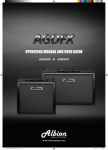
1. XLR Microphone Jacks
These jacks accept typical
3pin XLR inputs for balanced
and unbalanced signals. They
can be used in conjunction
with microphones–such as
p r o f e s s i o n a l c o n d e n s e r,
dynamic or ribbon microphones
– with standard XLR male
connectors, and feature low
QRLVHSUHDPSOL¿HUVVHUYLQJIRUFU\VWDOFOHDUVRXQG
replication. The AM 442D mixer features four
standard XLR microphone inputs, whereas the AM
642D features a total of six.
NB. When these inputs are used with condenser microphones,
WKH3KDQWRP3RZHUVKRXOGEHDFWLYDWHG+RZHYHUZKHQ3KDQWRP
Power is engaged, single ended (unbalanced) microphones and
instruments should not be used on the Mic inputs.
2. Line Inputs
This input accepts typical 1/4” TRS balanced or
TS unbalanced inputs, for balanced or unbalanced
signals. They can be used in conjunction with a wide
UDQJHRIOLQHOHYHOGHYLFHVVXFKDVNH\ERDUGVGUXP
PDFKLQHV HOHFWULF JXLWDUV DQG D YDULHW\ RI RWKHU
electric instruments.
3. Stereo Channels
The AM 442D and AM 642D also feature a few
VWHUHR FKDQQHOV WKURZQ LQ IRU PD[LPXP ÀH[LELOLW\
Each of these stereo channels features two 1/4”
SKRQH MDFNV IRU WKH DGGLWLRQ RI YDULRXV OLQH OHYHO
LQSXWGHYLFHVVXFKDVHOHFWURQLFNH\ERDUGVJXLWDUV
and external signal processors or mixers. If you wish
WRXVHDPRQDXUDOGHYLFHRQDVWHUHRLQSXWVLPSO\
SOXJWKHGHYLFH¶V´SKRQHMDFNLQWRWKHOHIWPRQR
LQSXWDQGOHDYHWKHULJKWLQSXWEDUH7KHVLJQDOZLOO
be duplicated to the right due to the miracle of jack
normalizing. The AM 442D and AM 642D feature
four stereo channels and include a +4/-10dB selector
VZLWFKIRUDPD[LPXPÀH[LELOLW\
4. AUX Returns
These 1/4” TS inputs are for the return of audio to
the AM 442D and AM 642D mixers, processed by
an external signal processor. If really needed, they
can also be used as additional inputs. The feed from
these inputs can be adjusted using the AUX Return
controls on the face of the mixer. When connecting
DPRQDXUDOGHYLFHWRWKH$8;5HWXUQDQGLQSXWV
simply plug a 1/4” phone jack into the left (mono)
input, and the signal will appear in the right as well.
7KLV KRZHYHU GRHV QRW ZRUN IRU WKH$8; 5HWXUQ
2 input on both AM442D/AM642D.When the AUX
Return 2 is used, the built-in digital effects processor
is automatically by-passed.
5. AUX Sends
These 1/4” TS outputs may be used to connect to
DQH[WHUQDOVLJQDOSURFHVVRURUHYHQWRDQDPSOL¿HU
and speakers (depending on your desired settings)
from the mixer. The signal from the AUX Sends is
controlled by the AUX master controls (on the face
of the mixer), which obtain their signal from the AUX
controls located on each channel strip. The AM
442D features 2 AUX sends, whereas the AM 642D
features a total of 3.
6. Foot Switch Jacks
This port is for the inclusion of a foot switch, used
to remotely turn the Digital Effects Processor on
and off.
7. Phones
This stereo output port is suited for use with
headphones, allowing monitoring of the mix. The
DXGLR OHYHO RI WKLV RXWSXW LV FRQWUROOHG XVLQJ WKH
Control Room / Phones control.
6
AM442D/642D
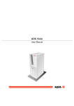
8. Record Out
These outputs will
DFFRPPRGDWH5&$FDEOHV
able to be fed to a variety
of recording devices.
9. 2T Return
7KHVH 5&$ LQSXWV DUH
used to connect the mixer
ZLWKH[WHUQDOGHYLFHVVXFK
DV&'7DSHDQG&DVVHWWH
Players.
10. Main Out
7KHVHWZR;/5MDFNVZLOO
output the final stereo
line level signal sent from
the main mixing bus. The
primary purpose of these
MDFNVLVWRVHQGWKHPDLQRXWSXWWRH[WHUQDOGHYLFHV
ZKLFKPD\LQFOXGHSRZHUDPSOL¿HUVDQGLQWXUQD
SDLU RI VSHDNHUV RWKHU PL[HUV DV ZHOO DV D ZLGH
UDQJHRIRWKHUSRVVLEOHVLJQDOSURFHVVRUV(TXDOL]HUV
&URVVRYHUVHWFHWHUD
Rear Panel
11. Channel Inserts
/RFDWHGRQWKHUHDURIWKH$0'DQG$0'
WKH SULPDU\ XVH IRU WKHVH 756 SKRQH MDFNV LV IRU
WKH DGGLWLRQ RI H[WHUQDO GHYLFHV VXFK DV G\QDPLF
SURFHVVRUVRUHTXDOL]HUVWRPRQRLQSXWFKDQQHOV
through to 4 on the AM 442D and 1 through 6 on the
AM 642D. This send and return will require a Y cord
that can send (pre-fader and pre-EQ) and receive
signals to and from an external processor.
AM442D/642D
12. Control Room Outputs
7KHVHWZR´SKRQHMDFNRXWSXWVIHHGWKHVLJQDO
DOWHUHGE\WKH&RQWURO5RRP3KRQHVOHYHOFRQWURO
on the face of the mixer. This output has extensive
XVH DV LW FDQ EH XVHG WR IHHG WKH VLJQDO IURP WKH
PL[HUWRDQDFWLYHPRQLWRUIRUWKHPRQLWRULQJRIWKH
DXGLRVLJQDOIURPZLWKLQDERRWKRUDOWHUQDWLYHO\IRU
the addition of external signal processing devices
RU PL[HUV DV ZHOO DV DFWLQJ DV D ³VLGH ¿OO´ RXWSXW
supplying audio to indoor areas that the main
speakers do not reach.
13. Group Out
7KHVH ´ SKRQH MDFNV RXWSXW WKH ¿QDO IHHG IURP
the Group 1 and 2 Faders on the main mixer. These
RXWSXWVFDQEHXVHGWRIHHGDZLGHUDQJHRIGHYLFHV
VXFK DV PL[HUV VLJQDO SURFHVVRUV DQG HYHQ WR
FRQQHFWDQDPSOL¿HUDQGVSHDNHUVWREHXVHGDORQJ
ZLWKWKH0DLQ6SHDNHUVIRUDPRUHURXQGHGDXGLR
experience.
14. Main Out
7KHVH WZR ;/5 SRUWV ZLOO RXWSXW WKH ¿QDO VWHUHR
line level signal sent from the main mixing bus.
7KHSULPDU\SXUSRVHRIWKHVHMDFNVLVWRVHQGWKH
PDLQRXWSXWWRH[WHUQDOGHYLFHVZKLFKPD\LQFOXGH
SRZHU DPSOL¿HUV DQG LQWXUQ D SDLU RI VSHDNHUV
RWKHU PL[HUV DV ZHOO DV D ZLGH UDQJH RI RWKHU
SRVVLEOHVLJQDOSURFHVVRUVHTXDOL]HUVFURVVRYHUV
etcetera).
7
15. Power Connector
This port is for the addition of a power cable, allowing
power to be supplied to the mixer. Please use the
power cable that is included with this mixer only.
Controls and Settings
Rear Panel
16. Phantom Power Switch
When this switch is in the on position, it activates
+48V of phantom power for all microphone inputs,
allowing condenser microphones (well, the ones that
don’t use batteries) to be used on these channels.
Activating Phantom Power will be accompanied by
an illuminated LED above the left channel Level
Meter. Before turning Phantom Power on, turn all
level controls to a minimum to avoid the possibility of
a ghastly popping sound from the speakers.
NB. Phantom Power should be used in conjunction
with balanced microphones. When Phantom Power
is engaged, single ended (unbalanced) microphones
and instruments should not be used on the Mic
inputs. Phantom Power will not cause damage to
most dynamic microphones. If unsure, however, the
microphone’s user manual should be consulted.
17. Power Switch
This switch is used to turn the mixer on and off.
Ensure you turn all level controls down before
activating.
Channel Controls
18. Low Cut Filter (75 Hz)
7KLVEXWWRQZLOODFWLYDWHDKLJKSDVV¿OWHUWKDWUHGXFHV
all frequencies below 75 Hz at 18 dB per Octave,
helping to remove any unwanted ground noise or
stage rumble. This Low Cut Filter is only available on
Mic channels on both the AM 442D and AM 642D.
19. Line/Mic Gain Control
This controls the sensitivity of the input signal of the
Line/Microphone input. The gain should be adjusted
to a level that allows the maximum use of the audio,
while still maintaining the quality of the feed. This can
be accomplished by adjusting it to a level that will
allow the peak indicator occasionally illuminate.
20. High Frequency Control
This control is used to give a shelving boost or cut of
±15 dB to high frequency (12 kHz) sounds. This will
adjust the amount of treble included in the audio of
the channel, adding strength and crispness to sounds
such as guitars, cymbals, and synthesizers.
21. Middle Frequency Control
This control is used to provide a peaking style of
boost and cut to the level of middle frequency sounds
at a range of ±15 dB. These mixers also provide
a sweep control, allowing you to select a center
frequency between 100 Hz and 8 kHz. Changing
middle frequencies of an audio feed can be rather
GLI¿FXOWZKHQXVHGLQDSURIHVVLRQDODXGLRPL[DV
it is usually more desirable to cut middle frequency
sounds rather than boost them, soothing overly harsh
vocal and instrument sounds in the audio.
The stereo channels feature High-Mid and Low-Mid
controls instead of the typical controls described
above. They provide a peaking style of boost and cut
to middle frequencies, where the frequencies are set
at 3 kHz and 800 Hz, respectively.
22. Low Frequency Control
This control is used to give a shelving boost or cut
of ±15 dB to low frequency (80 Hz) sounds. This will
adjust the amount of bass included in the audio of
the channel, and bring more warmth and punch to
drums and bass guitars.
23. AUX Control
This control alters the signal level that is being sent
to the auxiliary 1 mixing bus, the signal of which
is suitable for connecting stage monitors, allowing
artists to listen to the music that is being played.
Also included is a Pre/Post button which alternates
the feed to the AUX mixing bus between a post and
pre-fader feed.
8
AM442D/642D
24. EFX Control
This control alters the signal level that is sent to the
EFX send (AUX 2 on the AM 442D, AUX 3 on the AM
642D) output and the built-in digital effect processor.
The EFX send signal can be used in conjunction with
external signal processors (this signal of which can
be returned to mixer via the AUX return input), or
simply as an additional auxiliary output.
25. Pan / Balance Controls
This alternates the degree or level of audio that the
left and right side of the main mix should receive. On
Mic channels, the PAN control will adjust the level
that the left and right should receive (pan), where as
on a stereo channel, adjusting the BAL control will
attenuate the left or right audio signals accordingly
(balance).
26. O n B u t t o n a n d
Indicator
This turns the channel on,
allowing the user to use
the feed from the channel’s
inputs to supply the MAIN
L/R, GROUP 1/2, AUX
and EFX buses. The
corresponding indicator
will be illuminated when
turned on.
27. 1-2 and L/R Buttons
These handy buttons allow you to decide the audio
path of the corresponding channel. Pushing the “12” button allows the signal to be sent to the Group
1-2 mix, where the “L/R” allows it to be sent to the
Main L/R mix.
28. Peak Indicator
This LED indicator will illuminate when the channel
hits high peaks, 6 dB before overload occurs. It is
best to adjust the channel level control to a level
slightly prior to the peak indicator does not light up.
This will ensure a greater dynamic range of audio.
This indicator also doubles as a Solo indicator, when
the SOLO button is engaged.
Digital Effect Processor
31. Digital Effect Display
This 2-digital numeric display shows the program
number that is currently applied to your EFX audio
signal. When you rotate the Program control, you can
scroll through different program numbers; however
the display will revert back to the original program if
a new program is not selected within a few seconds.
For a list of available effects, please observe the
Digital Effect Table.(When the Digital Effect Processor
is put into stand-by mode (by use of the foot switch or
on button) the 2 small dots within the numeric display
ZLOOÀDVK,QWKLVPRGHXVHUVDUHVWLOODEOHWRSUHYLHZ
and select new effect programs.)
32. Sig and Clip Indicators
Located within the Digital Effect Display are Clip
and Sig LEDs. The Sig LED will light up when any
signal is received by the effect processor, and the
Clip LED will light up shortly before excessive signals
are dynamically clipped. If the Clip LED lights up too
often, it may be advisable to turn down one or all EFX
controls on input channels to ensure the signal level
is not too high.
33. Program Control
This control is used to scroll through the various
effects. Turning the control clockwise will allow users
to ascend into higher program numbers, and turning
it counter-clockwise will allow users to descend
into lower program numbers. Pushing this control
will apply the new effect. When a tap-delay effect
is selected, pressing this control will allow users to
select the tap-delay time.
By pushing the button several times, the effect
processor interprets the time between last two
pushes and remembers this as the delay time, until
the button is pushed again (this is kept, even after
the power is turned off). When the tap delay effect is
VHOHFWHGDVPDOO/('ZLOOÀDVKZLWKLQWKHGLJLWDOHIIHFW
display window at the selected intervals.
34. DFX On Button and Indicator (AM642D
29. Solo Button
The Solo button is pushed to allow the signal of a
corresponding channel to be sent to the Control
Room / Phones control. The signal is either that of a
pre- or post-fader depending on the pre/post button
in the master section.
30. Level Faders
These faders allow users to adjust the level of the
signal from the corresponding input channel that is
to be sent to the destinations selected by the 1-2
and L/R buttons.
AM442D/642D
9
Master Section
35. AUX Return Controls
7KHVHFRQWUROVDGMXVWWKHVLJQDOOHYHORIDXGLRIHG
WKURXJKWRWKHVWHUHR$8;5HWXUQLQSXWV7KH³7R$8;
´FRQWURODGMXVWVWKHSUHIDGHUOHYHORIWKHVLJQDOIURP
the AUX Return inputs to the AUX 1 mixing buses.
36. EFX Return (AUX Return 2) Control
7KLV FRQWURO DGMXVWV WKH VLJQDO OHYHO RI DXGLR IHG
through to stereo AUX Return 2 inputs. If no device
LVSOXJJHGLQWRWKH$8;5HWXUQLQSXWVWKLVFRQWURO
WKHQDFWVDVWKH¿QDOOHYHOFRQWURORIWKHEXLOWLQ'LJLWDO
Effect Engine.
37. Main L/R and Group 1-2 Buttons
The EFX Return control on the AM442D is
accompanied by a Main L/R / Group 1-2 button. In
WKHFDVHRIWKH$0WKHUHDUHEXWWRQVRQHIRU
0DLQ/5DQGRQHIRU*URXSERWKRIZKLFKFDQ
EH XVHG VLPXOWDQHRXVO\ ,Q ERWK FDVHV KRZHYHU
these buttons change the destination of the EFX
Return signal between the Main L/R signal and/or
Group 1-2 sub mix.
38. Return Solo Buttons (AM642D)
Pushing either of the AM642D’s Return Solo buttons
allows users to send the signal from the AUX Returns
DQGRU WR WKH &RQWURO 5RRP 3KRQHV PL[LQJ
bus.
39. AUX Send Master Control
7KLVFRQWURODGMXVWVWKH¿QDOOHYHORIWKH$8;PL[LQJ
bus (as taken from the AUX level controls on each
FKDQQHOVWULSWKHDXGLRRIZKLFKLVVHQWWR$8;6HQG
RXWSXW7KHFRUUHVSRQGLQJ62/2EXWWRQDOORZV\RX
WRVHQGWKH$8;6HQGVLJQDOWRWKH&RQWURO5RRP
3KRQHVPL[LQJEXV7KH$0'IHDWXUHVVHQGV
ZKHUHWKH¿UVWLVLQIDFWDPPIDGHUUDWKHUWKDQ
10
the simple rotary control. Also incorporated with the
$8; FRQWURO RI WKH$0 ' LV D 3HDN /(' DV
ZHOODVDQ21EXWWRQDQGLQGLFDWRUDOORZLQJ$8;
to be activated and muted when required. Activation
RI$8; 6HQG LV RI FRXUVH DFFRPSDQLHG E\ DQ
illuminated LED.
40. EFX Send Master Control
7KLVFRQWURODGMXVWVWKH¿QDOOHYHORIWKH();PL[LQJ
bus (as taken from the EFX level controls on each
FKDQQHOVWULSWKHDXGLRRIZKLFKLVVHQWWRWKH$8;
Send 2 (on the AM 442D) or the AUX Send 3 (on
WKH$0'RXWSXWVDVZHOODVWKHEXLOWLQGLJLWDO
HIIHFWHQJLQH7KHFRUUHVSRQGLQJ62/2EXWWRQDOORZV
\RXWRVHQGWKHVLJQDOWRWKH&RQWURO5RRP3KRQHV
mixing bus.
41. Control Room / Phones Controls
7KLVFRQWUROLVXVHGWRDGMXVWWKHDXGLROHYHORIWKH
3KRQHVIHHGDVZHOODVWKHVLJQDOVHQWWRWKH&RQWURO
5RRPRXWSXWIRUXVHLQPRQLWRULQJDQGWUDFNLQJRI
audio.
Priority
Signal
+LJKHVW
Medium
Lowest
From Solo
75HWXUQWR&RQWURO5RRP
Main L/R
42. Pre / Post Control
7KLV EXWWRQ DOWHUQDWHV WKH &RQWURO 5RRP 3KRQHV
source signals between those of post-fader and
pre-fader feeds.
AM442D/642D
43. 2T Return Controls
7XUQLQJWKH75HWXUQOHYHOFRQWURODGMXVWVWKHVLJQDO
OHYHORIWKHIHHGIURPWKH75HWXUQLQSXWVWKHVLJQDO
of which is sent to the Main L/R mixing bus. Pushing
WKH ³WR &WUO 5P´ EXWWRQ IHDWXUHG RQ WKH$0'
RQO\VHQGVWKHVLJQDOWRWKH&RQWURO5RRP3KRQHV
mixing bus also.
44. +48V Indicator
This indicator will illuminate when Phantom Power
is activated.
45. Power Indicator
The Power Indicator will light up when the power of
the mixer is on; in case you weren’t too sure.
46. Level Meter
This dual 12-segment level meter gives an accurate
indication of when audio levels of the Main L/R output
reach certain levels. The 0 dB indicator illuminates
is approximately equal to an output level of +4 dBu
EDODQFHG DQG WKH 3($. LQGLFDWRU LOOXPLQDWHV
slightly before the signal is dynamically clipped. It is
suggested that users set the various levels controls
so that the level meter sits steadily around the 0
dB mark to make full use of the audio while still
maintaining fantastic clarity.
47. Group Controls
7KHVHWZRIDGHUVDUHWKH¿QDOOHYHOFRQWUROIRUWKH
*URXSDQGDXGLRIHHGVVHQWWRWKH*URXSDQG
2 outputs. These faders can be fed a signal from the
YDULRXVPRQRDQGVWHUHRFKDQQHOVDVZHOODV();
5HWXUQVGHSHQGLQJRQ\RXUVHOHFWLRQV:KHQSXVKHG
DOOWKHZD\XSWKHVHIDGHUVSURYLGHG%RIJDLQWR
WKHVLJQDODQGZKHQVHWDOOWKHZD\GRZQHIIHFWLYHO\
PXWH WKH VLJQDO 7KH *URXS &RQWUROV DOVR IHDWXUH
/HIWDQG5LJKWEXWWRQVZKLFKDOORZ\RXWRVHQGWKH
Group 1-2 signals to the Main Left and Right mixing
buses. The AM442D also features a solo button
accompanying each of the Group controls.
48. Main L/R Faders
7KHVHWZRIDGHUVDUHWKH¿QDOOHYHOFRQWUROIRUWKH
0DLQ/HIWDQG5LJKWDXGLRIHHGVVHQWWRWKH0DLQ/
and R outputs. These faders are possibly fed by the
YDULRXVPRQRDQGVWHUHRFKDQQHOVDVZHOODV$8;
DQG();UHWXUQVDQG7LQSXWVGHSHQGLQJRQWKH
\RXUVHOHFWLRQV:KHQSXVKHGDOOWKHZD\XSWKHVH
IDGHUVSURYLGHG%RIJDLQWRWKHVLJQDODQGZKHQ
VHWDOOWKHZD\GRZQHIIHFWLYHO\PXWHWKHVLJQDO
When the Solo indicator (located beside the Level
0HWHU LV LOOXPLQDWHG RQH RU PRUH 6ROR EXWWRQV
has been pushed and the Level meter will display
SURSHUWLHVRIWKH6RORVLJQDOZKLFKFDQEHKHOSIXO
with setting of channel properties. If Solo indicator
LOOXPLQDWHVJUHHQWKLVPHDQVWKH6RORIHHGLVDSUH
IDGHUVLJQDO,IWKHVRORLQGLFDWRULOOXPLQDWHVUHGWKH
IHHGLVSRVWIDGHU,IWKHQR6ROREXWWRQVDUHDFWLYDWHG
the 2T Return signal properties are displayed by the
/HYHO 0HWHU XQOHVV WKH 7R &WUO 5P EXWWRQ LV QRW
SUHVVHGLQZKLFKFDVHWKH0DLQ/5VLJQDOSURSHUWLHV
will be displayed.
Priority
+LJKHVW
Medium
Lowest
AM442D/642D
Signal
From Solo
75HWXUQWR&RQWURO5RRP
Main L/R
11
49. Graphic Equalizer (AM 642D)
7KLVVWHUHREDQGJUDSKLFHTXDOL]HUDOORZVWKHXVHU
WRDGMXVWWKHIUHTXHQF\UHVSRQVHRIDVLJQDOZLWKD
maximum of ±12 dB of signal boost or cut for each of
WKHIUHTXHQFLHV7KH$8;0$,1VZLWFKDOWHUQDWHV
WKHXVHRIWKHHTXDOL]HUEHWZHHQWKHXVHRIWKH$8;
EXVDQG0$,1/5EXVVLJQDOV3XVKLQJWKHRQEXWWRQ
LQDFWLYDWHVWKHHTXDOL]HUZKLFKLVDFFRPSDQLHGE\
an illuminated LED.
12
AM442D/642D
Application
2QWKHIROORZLQJFRXSOHRISDJHV\RXZLOO¿QGDZLGHUDQJHRISRVVLEOHXVHVIRUWKH$0PL[HUV2IFRXUVH
WKHVHDUHIDUIURPWKHRQO\DSSOLFDWLRQVWKDWFDQEHDWWULEXWHGWRWKHPL[HUV¶XVHKRZHYHUWKH\VKRXOGJLYH\RX
DQLGHDRIWKHSRVVLEOHXVHVWKDWWKHYDULRXVLQSXWVDQGRXWSXWVKDYH7KHULJKWFRPELQDWLRQRIPLFURSKRQHV
JXLWDUVGUXPPDFKLQHVNH\ERDUGVDVZHOODVUHFRUGLQJGHYLFHVVLJQDOSURFHVVRUVDPSOL¿HUVDQGVSHDNHUV
FDQPDNHIRUWKHSHUIHFWOLYHSHUIRUPDQFHKRPHVWXGLRUHFRUGLQJVHVVLRQRUHYHQDEDVLFSXEOLFDGGUHVVWR
name a few.
AM442D/642D
13
14
AM442D/642D
DIGITAL EFFECT TABLE
NO
PROGRAM NAME
PARAMETER SETTING
ROOM
REV-TIME
EARLY LEVEL
00
COMPACT ROOM 1
0.05
100
01
COMPACT ROOM 2
0.4
02
SMALL ROOM 1
03
SMALL ROOM 2
04
05
NO
PROGRAM NAME
PARAMETER SETTING
PAN
SPEED
56
SLOW PAN
0.1
TYPE
R-->L
0
57
SLOW PAN 1
0.1
R<-->L
0.45
100
58
SLOW PAN 2
0.4
R-->L
0.6
90
59
MID SHIFT
0.8
R<-->L
MID ROOM 1
0.9
100
60
MID SHIFT 1
1.2
L-->R
MID ROOM 2
1
50
61
MID SHIFT 2
1.8
L-->R
06
BIG ROOM 1
1.2
100
62
MID SHIFT 3
1.8
R-->L
07
TUNNEL
3.85
100
63
FAST MOVE
3.4
R<-->L
HALL
REV-TIME
EARLY LEVEL
TREMOLO
SPEED
MODE-TYPE
08
JAZZ CLUB
0.9
90
64
LAZY TREMOLO
0.8
TRG
72
65
VINTAGE TREMOLO
1.5
TRG
09
SMALL HALL 1
1.5
10
SMALL HALL 2
1.75
85
66
WARM TREMOLO
2.8
TRG
11
SPRING HALL
1.9
98
67
WARM TREMOLO 1
4.6
TRG
12
MID HALL 1
2.3
100
68
HOT TREMOLO
6.8
TRG
13
MID HALL 2
2.45
80
69
HOT TREMOLO 1
9.6
TRG
14
RECITAL HALL
2.7
96
70
CRAZY TREMOLO 1
15
TRG
15
BIG HALL 2
3.3
88
71
CRAZY TREMOLO 2
20
PLATE
REV-TIME
HPF
DELAY+REV
REV
TRG
DELAY-1
16
SMALL PLATE
0.9
0
72
DELAY+REV 1
1
17
TAIL PLATE
1.2
20
73
DELAY+REV 2
2
2
18
MID PLATE 1
1.3
0
74
DELAY+REV 3
3
3
1
19
MID PLATE 2
2.2
0
75
DELAY+REV 4
4
4
20
REVERSE PLATE
2.25
42
76
DELAY+REV 5
5
5
21
LONG PLATE 1
2.6
80
77
DELAY+REV 6
6
6
22
LONG PLATE 2
3
625
78
DELAY+REV 7
7
7
23
LONG PLATE 3
4.2
0
79
DELAY+REV 8
8
8
DELAY-1(stereo)
DELAY AVERG.
R-LEVEL
CHORUS+REV
REV
CHORUS
24
SHORT DELAY 1
0.07
60
80
CHORUS+REV 1
1
1
25
SHORT DELAY 2
0.14
60
81
CHORUS+REV 2
2
2
26
PING PONG DELAY
0.11
55
82
CHORUS+REV 3
3
3
27
MID DELAY 1
0.15
55
83
CHORUS+REV 4
4
4
28
MID DELAY 1
0.3
60
84
CHORUS+REV 5
5
5
29
SHORT DELAY 1 (MONO)
0.06
100
85
CHORUS+REV 6
6
6
30
MID DELAY 1 (MONO)
0.13
100
86
CHORUS+REV 7
7
7
31
LONG DELAY 1 (MONO)
0.18
100
87
CHORUS+REV 8
8
8
CHORUS
LFO
DEPTH
FLANGER+REV
REV
FLANGER
32
SOFT CHORUS
0.2
56
88
FLANGER+REV 1
1
1
33
SOFT CHORUS 2
0.5
70
89
FLANGER+REV 2
2
2
34
SOFT CHORUS 3
0.8
75
90
FLANGER+REV 3
3
3
35
WARM CHORUS
1.8
85
91
FLANGER+REV 4
4
4
36
WARMER CHORUS 1
3.2
80
92
FLANGER+REV 5
5
5
37
WARMER CHORUS 2
5.2
45
93
FLANGER+REV 6
6
6
38
WARMER CHORUS 3
7.8
52
94
FLANGER+REV 7
7
7
39
HEAVY CHORUS
9.6
48
95
FLANGER+REV 8
8
8
FLANGER
LFO
DEPTH
GATED-REV
RELEASE
REV
40
CLASSIC FLANGER 1
0.1
44
96
GATED-REV-1 9
0.02
TAIL PLATE
41
CLASSIC FLANGER 2
0.3
63
97
GATED-REV-2 10
0.2
TAIL PLATE
42
GENTLE FLANGER
0.6
45
98
GATED-REV-1 9
0.02
REVERSE PLATE
43
WARM FLANGER
1.6
60
99
GATED-REV-2 10
0.5
REVERSE PLATE
44
MODERN FALANGER 1
2
85
TAP DELAY
FB LEVEL
RANGE
45
MODERN FALANGER 2
2.8
80
A0
TAP DELAY
0
100mS - 2.7S
46
DEEP FALANGER 1
4.6
75
A1
TAP DELAY
10
100mS - 2.7S
47
DEEP FALANGER 2
10
60
A2
TAP DELAY
20
100mS - 2.7S
PHASER
LFO
DELAY
A3
TAP DELAY
30
100mS - 2.7S
48
CLASSIC PHASER 1
0.1
3.6
A4
TAP DELAY
40
100mS - 2.7S
49
CLASSIC PHASER 2
0.4
2.6
A5
TAP DELAY
50
100mS - 2.7S
50
COOL PHASER
1.4
0.7
A6
TAP DELAY
60
100mS - 2.7S
51
WARM PHASER
3.2
0.3
A7
TAP DELAY
70
100mS - 2.7S
52
HEAVY PHASER 1
5
1.2
A8
TAP DELAY
80
100mS - 2.7S
53
HEAVY PHASER 2
6
2.8
54
WILD PHASER 1
7.4
0.8
T0
55
WILD PHASER 2
9.6
4.8
T1
MID FREQUENCY
1kHz
SINEWAVE
T2
HIGH FREQUENCY
10kHz
SINEWAVE
PN
PINK NOISE
20Hz~20kHz
AM442D/642D
TEST TONE
FREQUENCY
SHAPE
LOW FREQUENCY
100Hz
SINEWAVE
15
SPECIFICATIONS
AM442D
AM642D
8
10
Inputs
Total Channels
Balanced Mono Mic / Line channel
4
6
Balanced Stereo Line Channel
4
4
2 stereo
2 stereo
Stereo RCA
Stereo RCA
2 x 1/4” TRS, Bal. & 2 x XLR
2 x 1/4” TRS, Bal. & 2 x XLR
Rec Out
Stereo RCA
Stereo RCA
CTRL RM L/R
2 x 1/4” TS
2 x 1/4” TS
Phones
1
1
Channel Strips
8
10
Aux Sends
2
3
Aux Return
2T Input
Outputs
Main L/R Stereo
Pan/Balance Control
Yes
Yes
Channel insert
CH 1~ CH 4
CH 1~ CH 6
Volume Controls
60mm fader
60mm fader
Aux Send Masters
2
3
Master Aux Send Solo
2
3
Stereo Aux Returns
2
2
Aux Return Assign to Subgroup
1
1
Effects Return to Monitor
2
2
Global AFL/PFL Solo Mode
Yes
Yes
Phones Level Control
Yes
Yes
2 subgroups, Main L & R
Aux return 2, Aux 1, 2 subgroups,
Main L & R
Number of Channels
2
2
Segments
12
12
+48V DC
+48V DC
Master
Master
100 effects with tap delay control, Test tone and foot switch
(effect on/off)
100 effects with tap delay control,
Test tone and foot switch
(effect on/off)
Master Section
Faders
Metering
Phantom Power Supply
Switches
32/40-bit Digital Effect Processor
Built-in Graphic EQ
N/A
Stereo 9-band
60, 160, 315, 630, 1.25K, 2.5K, 5K,
10K, 16K Hz
Center Frequency
Range
±12 dB
Frequency Response (Mic input
to any output)
20Hz ~ 60KHz
+0/-1 dB
+0/-1 dB
20Hz ~ 100KHz
+0/-3 dB
+0/-3 dB
16
AM442D/642D
Crosstalk (1KHz @ 0dBu, 20Hz
to 20KHz bandwidth, channel in to
main L/R outputs)
Channel fader down, other channels
<-90 dB
<-90 dB
-86.5 dBu
-86.5 dBu
-84 dBu
-84 dBu
>90 dB
>90 dB
<-129.5 dBm
<-129.5 dBm
<0.005%
<0.005%
80dB
80dB
Mic Preamp Input
+10dBu
+10dBu
All Other Input
+21dBu
+21dBu
Balanced Output
+28dBu
+28dBu
2 K ohms
2 K ohms
at unity
Noise (20Hz~20KHz; measured at
main output, Channels 1-4 unit gain;
(4ÀDWDOOFKDQQHOVRQPDLQPL[
channels 1/3 as far left as possible,
channels 2/4 as far right as possible. Reference=+6dBu)
Master @ unity, channel fader down
Master @ unity, channel fader @
unity
S/N ratio, ref to +4
Microphone Preamp E.I.N. (150
ohms terminated, max gain)
THD (Any output, 1KHz @ +14dBu,
20Hz to 20KHz, channel inputs)
CMRR (1 KHz @ -60dBu, Gain at
maximum)
Maximum Level
Impedance
Mic Preamp Input
All Other Input (except insert)
10 K ohms
10 K ohms
RCA 2T Output
1.1 K ohms
1.1 K ohms
3-band, +/-15dB
(4-band on Stereo Ch)
3-band, +/-15dB
(4-band on Stereo Ch)
80Hz
80Hz
Ch Equalization
Low EQ
Mid EQ (mono channel)
100-8k Hz, sweepable
100-8k Hz, sweepable
LMid EQ (stereo channel)
800 Hz
800 Hz
HMid EQ (stereo channel)
3 kHz
3 kHz
Hi EQ
12 kHz
12 kHz
75 Hz (-18 dB/oct)
75 Hz (-18 dB/oct)
100-240 VAC, 50/60 Hz
100-240 VAC, 50/60 Hz
9.25 lbs (4.2 kg)
10.6 lbs (4.8 kg)
11.8” x 3.5” x 13.4”
(300 x 89 x 340 mm)
16” x 3.5” x 14”
(407 x 89 x 357 mm)
/RZFXW¿OWHU
Built-in Power Supply
Weight
Dimensions (WxHxD)
AM442D/642D
17
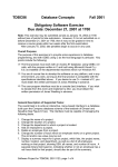
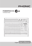
DIMENSIONS
88.0/3.5
AM442D
104.5/4.1
300.0/11.8
346.0/13.6
88.0/3.5
88.0/3.5
AM642D
103.5/4.0
407.0/16.0
357.0/14.0
88.0/3.5
18
AM442D/642D
R
+4/-10
3K
3K
AUX RTN2
AUX RTN1
R
L
R
L(MONO)
800
HMID LMID
HI
12K
800
HMID LMID
HI
12K
EQ
80
LO
80
LO
HI
MID
LO
FOOT SW
ON
ON
FREQ
8K 100 80
EQ
MID
12K
PEAK(SOLO)
LOW CUT
75Hz
HPF
STEREO CHANNEL5~12
L(MONO)
MONO CHANNEL 1~4
1
GAIN
INSERT
SIG
CLIP
RTN2
RTN1
FADER
ON
POST
PRE
BAL.
FADER
PROGRAM
32/40 BIT DSP
ON
PEAK(SOLO)
L/R
AUX2/EFX
AUX 1
SOLO
GP1/2
L/R
MAIN/GP1,2
TO AUX1
AU2/EFX
AUX1
SOLO
GP1/2
PAN
SOLO
FADER
R FADER
L FADER
PRE/POST
POST(RED)
PRE(GRN)
2T RTN
SOLO
AUX SEND 2
SOLO
AUX SEND1
RIGHT
LEFT
MAIN MIX
EFX IN
LOGIC
POST R
POST L
PRE R
PRE L
AUX2 EFX
AUX1
GP2
GP1
MAIN R
MAIN L
LINE IN
MIC IN
PH.PWR.
2
3
AM442D/642D
MAIN R
MAIN L
AUX SEND1
GP1,2
2
2
SOLO_CTRL
SOURCE
R
CTRL RM/
PHONE S
MAIN
GP1/2
REC OUT
L
2T RTN
AUX SEND 2
3
3
1
1
PHANTOM POWER
(GLOBAL SWITCH)
CTRL RM R
PHONE S
CTRL RM L
PEAK
+10
+7
+4
+2
0
-2
-4
-7
-10
-20
-30
-40
0dBu=0.775 V
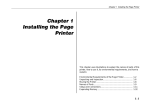
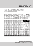
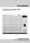
BLOCK DIAGRAMS
AM442D BLOCK DIAGRAMS
19
1
+4/-10
75Hz
HPF
LOW C UT
3K
12K
3K
800
HMID LMID
HI
12K
800
HMID LMID
HI
EQ
80
LO
80
LO
PEAK(SOLO)
FOOT SW
R
AUX RTN2
L
R
AUX RTN1
L(MONO)
STEREO CHANNEL7~14
R
L(MONO)
GAI N
MONO CHANNEL (1OF6)
LIN E IN
MIC IN
2
3
20
ON
CLIP
SIG
MID
LO
PROGRAM
ON
RTN1
AUX 1
SOLO
SOLO
L/R
GP1/2
AU3/EFX
TO AUX1
SOLO
L/R
GP1/2
AUX1
TO AUX1
POST
GP1/2
L/R
SOLO
PRE AUX2
BAL.
AUX3/EFX
AUX 2
FADER
PAN
RTN2 FADE R
FADER
ON
ON
PEAK(SOLO)
HDA 32BIT DSP
ON
ON
ON
FREQ
8K 100 80
EQ
MID
12K
HI
INS ERT
MAIN MIX
AUX3 SEND
AUX1 FADER
PRE/POS T
ON
R FADER
MAIN/AUX1
SOLO_CTRL
TO CTRL RM
CTRL RM/
PHONES
2T RTN
GP1 OUT
(GP2 OUT IDENTICAL)
GP1 FADER
40 80 160 315 630 1.25K 2.5K 5K 10K 16K
L FADER
2
2
2T RTN R
2T RTN L
3
3
CTRL RM R
PHONES
PEAK
+10
+7
+4
+2
0
-2
-4
-7
-10
-20
-30
-40
0dBu=0.775V
REC OUT R
REC OUT L
MAIN R OU T
MAIN L OUT
CTRL RM L
AUX SEND1
(AUX2 SEND IDENTICAL,ONLY AUX3 TO EFX)
40 80 160 315 630 1.25K 2.5K 5K 10K 16K
ON
PRE(GRN)
POST(RED)
RIGHT
LEFT
SOLO
SOLO
AUX3 SEND
1
EFX IN
LOGIC
POST R
POST L
PRE R
PRE L
AUX3 EFX
AUX2
AUX1
GP2
GP1
MAIN R
MAIN L
1
+48V
AM642D BLOCK DIAGRAMS
AM442D/642D
72385&+$6($'',7,21$/3+21,&*($5$1'$&&(6625,(6
7RSXUFKDVH3KRQLFJHDUDQGRSWLRQDODFFHVVRULHVFRQWDFWDQ\DXWKRUL]HG3KRQLFGLVWULEXWRU)RU
DOLVWRI3KRQLFGLVWULEXWRUVSOHDVHYLVLWRXUZHEVLWHDWZZZSKRQLFFRPDQGFOLFNRQ*HW*HDU<RX
PD\DOVRFRQWDFW3KRQLFGLUHFWO\DQGZHZLOODVVLVW\RXLQORFDWLQJDGLVWULEXWRUQHDU\RX
6(59,&($1'5(3$,5
3KRQLFKDVRYHUVHUYLFHFHQWHUVZRUOGZLGH)RUUHSODFHPHQWSDUWVVHUYLFHDQGUHSDLUVSOHDVH
FRQWDFW WKH 3KRQLF GLVWULEXWRU LQ \RXU FRXQWU\ 3KRQLF GRHV QRW UHOHDVH VHUYLFH PDQXDOV WR
FRQVXPHUVDQGDGYLFHXVHUVWRQRWDWWHPSWDQ\VHOIUHSDLUVDVGRLQJVRYRLGVDOOZDUUDQWLHV<RX
FDQORFDWHDGHDOHUQHDU\RXDWZZZSKRQLFFRP
:$55$17<,1)250$7,21
3KRQLFVWDQGVEHKLQGHYHU\SURGXFWZHPDNHZLWKDQRKDVVOHVZDUUDQW\:DUUDQW\FRYHUDJH
PD\ EH H[WHQGHG GHSHQGLQJ RQ \RXU UHJLRQ 3KRQLF &RUSRUDWLRQ ZDUUDQWV WKLV SURGXFW IRU D
PLQLPXPRIRQH\HDUIURPWKHRULJLQDOGDWHRISXUFKDVHDJDLQVWGHIHFWVLQPDWHULDODQGZRUNPDQ
VKLSXQGHUXVHDVLQVWUXFWHGE\WKHXVHU¶VPDQXDO3KRQLFDWLWVRSWLRQVKDOOUHSDLURUUHSODFHWKH
GHIHFWLYHXQLWFRYHUHGE\WKLVZDUUDQW\3OHDVHUHWDLQWKHGDWHGVDOHVUHFHLSWDVHYLGHQFHRIWKH
GDWHRISXUFKDVH<RXZLOOQHHGLWIRUDQ\ZDUUDQW\VHUYLFH1RUHWXUQVRUUHSDLUVZLOOEHDFFHSWHG
ZLWKRXWDSURSHU50$QXPEHUUHWXUQPHUFKDQGLVHDXWKRUL]DWLRQ,QRUGHUWRNHHSWKLVZDUUDQW\
LQHIIHFWWKHSURGXFWPXVWKDYHEHHQKDQGOHGDQGXVHGDVSUHVFULEHGLQWKHLQVWUXFWLRQVDFFRP
SDQ\LQJWKLVZDUUDQW\$Q\WHPSHULQJRIWKHSURGXFWRUDWWHPSWVRIVHOIUHSDLUYRLGVDOOZDUUDQW\
7KLVZDUUDQW\GRHVQRWFRYHUDQ\GDPDJHGXHWRDFFLGHQWPLVXVHDEXVHRUQHJOLJHQFH7KLV
ZDUUDQW\ LV YDOLG RQO\ LI WKH SURGXFW ZDV SXUFKDVHG QHZ IURP DQ DXWKRUL]HG 3KRQLF
GHDOHUGLVWULEXWRU)RUFRPSOHWHZDUUDQW\SROLF\LQIRUPDWLRQSOHDVHYLVLWKWWSZZZSKRQLFFRP
&86720(56(59,&($1'7(&+1,&$/6833257
:H HQFRXUDJH \RX WR YLVLW RXU RQOLQH KHOS DW KWWSZZZSKRQLFFRPKHOS 7KHUH \RX FDQ ILQG
DQVZHUVWRIUHTXHQWO\DVNHGTXHVWLRQVWHFKWLSVGULYHUGRZQORDGVUHWXUQVLQVWUXFWLRQDQGRWKHUKHOSIXO
LQIRUPDWLRQ:HPDNHHYHU\HIIRUWWRDQVZHU\RXUTXHVWLRQVZLWKLQRQHEXVLQHVVGD\
3KRQLF$PHULFD&RUSRUDWLRQ
-RKQV5RDG
7DPSD)/
VXSSRUW#SKRQLFFRP
KWWSZZZSKRQLFFRP