1
Bulletin
Delc<>-Re:n:1Y
1G-150
Date
7.3.61
ANDERSON. iNDiANA. U.S.A.
10 Pages
SERVICE
BULLETIN
Page 1
File Under:
G.GENERATORS
-
SIIpe"ed..
-.
Bulletin 10.1 SO
Dated 3.24-53
ADJUSTMENTS,TESTSAND MAINTENANCE OF
D.C. GENERATORS
GROUND
SCREW
'\
HINGE
CAPOilER
.....
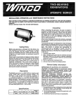
Fiaute I-Typic:al
D.C. Gene~tOf.
INTRODUCTION
TYPES AND DESIGNS
Delco-Remy d.c. generators are manufactured in
a wide range of sizes and types, but the basic d~
sign of each generator is the same. Regardless of
size, each generator has an armature mounted at
both ends on bearings. The armature rotates be.
tween pole shoes over which are wound field coils.
The voltage and current developed in the arma.
ture windings is supplied through brushes riding
on a commutator to the generator terminals, and
then to the battery and other electrical accessories
in the circuit. Since all d.c. generators adhere to
the same basic design, the maintenance and testing procedures for aU sizes are similar. A typical
generator is shown in Figure 1.
This bulletin covers the different types and designs
of d.c. generators along with recommended service
procedures for each. The subject of Operating
Principles is covered in Delco-Remy Training
Chart Manual DR-5133E.
The following cross sectional views illustrate the
various types of generators manufactured by
Delco-Remy.
co: 1.2. I WDS.
I'S, I.n,
131. 132:
16. If 0
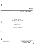
The extruded frame two-brush two-pole type of
generator shown in Figure 2 has a frame diameter
size of 4% inches. Each end frame has hinge cap
oilers for periodic lubrication, and the commutator end frame features a bronze bushing and an
oU reservoir. Continuous lubrication to the bushing and shaft is provided by a wick which extends
through a hole in the bushing to contact the shaft.
A special version in the 4% inch frame diameter
size is the generator shown in Figure 3. This assembly features a blast tube for forced air cooling,
and sealed ball bearings in each end frame which
are lubricated for the life of the bearing.
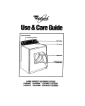
The generator shown in Figure 4 has a frcu:nediameter size of 51/8inches. It features ball bearings
!"'I"UD IN 1I.5.A.
:,.t
Service
Bulletin
IG..150
~
Page 2
D.C.GENERATORS
r""'" POI.E SHOE
i ,-POlE
SHOESCREW
!I
l1 !
INSULATION
7
,-OILER
-
flElO COIL,
,I,
l",
(BAll
1
""",;",
.,-:P'
",
""
I
SEARING
!
,
'",
'
U ii
d"1
!~,
,
/ Ii
WOOORuFF
L
KEY
,
Oil
SEAL
,oJ k
THRl/
~~
IJ
BOLT...!.
\ LSPRING
I
- r""Tmm_"\'>-COMMUTATOR
j.. ARMATURE
'
I
4-'
::
fAN
'
\.BRUSHj
,
\
COVERSAND
/"
L
LCOMMUTATOR
ENDfRAME
\
.(!~tpu:m AND~;~
"
,
,..
COMMUTATOR
DRIVE END FRAME
I
I
END FRAME.:J
ORIVEENDFRAME
Figure 2-Cross secUonal view of typical 4%" frame diameter
generator,
Flgut'\') 3-Cutaway view Qf typical 4%" frame diameter genera tor wiUt provision for forced all' cooling.
and hinge cap oilers in each end frame,and
a
cover band which can be removed for easy inspection of the brushes and commutator. This genera~
tor is of the two-brush two~pole type.
5% inches and a cover band that can be removed"
to permit easy inspection of the brushes and com",mutator.
In Figure 5 is illustrated a two~brush two-pole
generator which is similar in construction but
larger in size than the assembly shown in Figure
4. This generator has a frame diameter of 5% or
The generator illustrated in Figure {) has two
brushes, two poles, and a frame diameter size of
5% or 5% inches. This type generator features
grease reservoirs providing permanent-type lubri-
OilER
I
Il
0H
",.
,
'
,
BEARING
COMMUTATOR
END FRAME
FIELD COIL
ARMATURE
! (
--W
H
'
DRIVE END
FRAME
,
.
PUllEY
AND FAN
~J
FigUre 4-Cross sectional view of typical $!,jj"frame diameter generator.
-
Service
~
Bulletin
1G.150
Page 3
D.C. GENERA
TORS
OilER ;1
~
BEARING
,
-
:TI~,
I
i
,
ARMATURE
DRIVE
d;
,J.;
END'1j
FRAME
FilrUl'e ~ross
sectional view of typical generator having frame diameter
of 5%" or S~".
cation, and extra long brushes with special con~
stant-tension brush springs. These design features
eliminate the need for periodic lubrication and
brush replacement between engine overhaul
periods. Cover plates which are mounted over
windows in the field frame can be easily removed
for inspection of the brushes and commutator.
The assembly shown in Figure 7 has a frame di0
ameter size of 6n inches. The ball bearings in each
end frame in this generator are sealed for life,
and no periodic generator lubrication is required.
Generators in this frame size have four poles, and
some models have two brushes whereas. others
have four brushes.
.
! GREASE RESERVOIR
.
\
\\
.
.
HEAVY.DUTY
BAll
BEARING ...
I
~
L-
..
~
L-IIiiSPECTION
WINDOW
AND COVER PLATE
, "'--REPLACEABLE
SEAL
'-
......
MOUNTING BUSHING~
FIIrUI'e &-Cross sectional view of 5%" or $%" frame diameter generator with special
brushes and pemument bearing lubrication.
Service, Bulletin
1G..150
r7""=:-'
Page 4
.
D.C. GENERATORS
+ll!?))
Li'-'~'~<"--
~
I :
BEARING
ARMATURE
SEARING ""'"
COMMVTATOR
END FRAME
I
FIElD COIL
-
,-j
Figure 7-Cr()$$ sectional view of typical Gn" frnme diameter
The generator illustrated in Figure 8 is afour~
brush four-pole unit having a frame diameter of
61'\ inches. On this type generator, a roller hear~
ing is used in the drive end frame, and a ball bear~
ing in the commutator end frame. The inner race
of the ball bearing is secured to the shaft with a
nut threaded oyer the shaft at the commutator
end. Grease cups afe used on each end frame for
periodic lubrication.
generator.
The assembly io Figure 9 has four brushes and
four poles and a frame diameter of 8i~ inches.
00 some models the four neld coils aTe connected
in series, and io other models a split field arrangement is used as shown in Figure 17. Provision is
made on the commutator end frame for attachment of a filter screen to remove dust, dirt, and
other foreign material from the cooling air drawn
POU SHOE
if
, aC-"'fu,
COMMUTATOR
END FRAME
GREASECUP
-FAN
ARMATURE
FIgure g Cross sectional view of Iyplcal Ih"," frame diameter generlltor.
Service
~
i:r>'"~
~-u
,
Bulletin
iU d
v~~
IG.150
Page 5
,
D.C. GENERATORS
GREASE ARMATURECUP
TERMINAL
/
FIELDTERMINAL(F. J)
~,
.. -A .:~
'.. ,_.j(C"ELO~~~L~
U_-JJ
~
.
CUP
/GREASE
GROUND TERMINAL
r1
'-.
....
IF-2)
!
I
,.;
.--' " " "
"1r.s:"
'
'~
'"
-'~"C
..