1
WRBCC
~
SERVICE MANUAL 5122
TIME CODE
CONTROL SYSTEM
Type L-Form 506
and
Type L-Form 506-A
MAINTENANCE INSTRUCTIONS
I
.,_
......
••
April, 1979
B-79-500-2312-5
UNION SWITCH & SIGNAL DIVISION
AMERICAN STANDARD, INC.
Swissvale, PA 15218
ll "
--/
I
WA.CD
~
TABLE OF CONTENTS
LIST OF FIGURES
PART I
Page
Diagrams for Reference. . . . . . . . . . . . . . . . . . . . . . . . . . 1
Recommended Maintenance Procedure. . . . . . . . . . . . 1
PART II
Reshopping Procedure for Interchangeable Units and
KP Polar Relays . . . . . . . . . . . . . . . . . . . . . . . . . . . . .
General Procedure. . . . . . . . . . . . . . . . . . . . . . . . . .
Mechanical Inspection of Units and Included
Relays ...................................
Style "L" Relays ............................
Style "KP" Polar Relays. . . . . . . . . . . . . . . . . . . . .
Apparatus and Set-up for Making Operation,
Timing, and Voltage Tests on Complete Units.
Thermal Cutout on 506 System Units. . . . . . . . .
Thermal Cutout on 506-A System Units. . . . . . .
Code Timing. . . . . . . . . . . . . . . . . . . . . . . . . . . . . . .
Tests of Units on Voltage Limits. . . . . . . . . . . . .
2
2
2
3
3
4
4
4
5
6
PART III
Field Maintenance Tests . . . . . . . . . . . . . . . . . . . . . . . . .
General...................................
Timing of Units in Service. . . . . . . . . . . . . . . . . . .
Field Inspection of KP Polar Relays. . . . . . . . . . .
Service Tests for Thermal Cutout in 506-A
Units...................................
Plug Connectors . . . . . . . . . . . . . . . . . . . . . . . . . . . .
Figure I-Cycle Recorder Connections to Code Units • . • 4
Figure 2-Snap Action Thermal Cutout (Plan View) . • • • S
Figure 3-Circuit Diagram for Checking KP Relay
Calibrations . . • • . . . . . . • • • . . . . . . • • • • • • . . . 9
Figure 4-Contact Adjustments • . . . • . . . . . • . . • . • . • 10
Figure 5-KP Relay Wiring Diagrams. • • . • • . . • • . • • . . 11
7
7
7
8
LIST OF TABLES
Table I-Approximate Release Time of Slow Release
Relays................................ 6
Table 2-Timing Table. . . . . . . • . . . • . . . . • . . . . . . . 7
Table 3-In Service Timing of Office Units & Field
Units in DC Code Sections . • . . . . . . • . • . . . . . . . 8
Table 4-In Service Timing of Field Units as Measured at
the Office for Coded Carriers Controlled Sections . . . 8
Table 5-KP Polar Relay Calibration. . . • . . . . . . . . . . . 9
Table 6-Relay Wiring Diagram Nomenclature . . . . . . . . 11
Table 7-Field Code-Setting Connections. . . . . . . . . . • . 11
9
9
PART IV
Inspection Procedure for Control Cabinet .........
Office Storage Units.. . . . . . . . . . . . . . . . . . . . . . .
Levers and Pushbuttons . . . . . . . . . . . . . . . . . . . . .
Automatic Train Graph .....................
10
10
10
10
PART V
General Information. . . . . . . . . . . . . . . . . . . . . . . . . . . . 11
Field Code-Setting Connections. . . . . . . . . . . . . . 11
Catalog Plate T-575. . . . . . . . . . . . . . . . . . . . . . . . . 12
PART I
Diagrams for Reference
506
System
506-A
System
Circuit Diagram-Office Line-Coding
Unit ................. D-2547 Sh. 1
Sh.
Circuit Diagram-Field Line-Coding
Sh.
Storage Unit .......... D-2547 Sh. 2
Circuit Diagram-Office & Field
Sh.
Pyramid Unit ......... D-2547 Sh. 3
Graphic Code Chart ................... D-2547 Sh. 4
Sh.
Sh.
Circuit Diagram-Test Set .............. D-2547 Sh. 5
Sh.
Wiring Diagram-Office L-C Unit........ C-9362 Sh. 523
Wiring Diagram-Field Storage-Unit ..... C-9362 Sh. 524
Sh.
Sh.
Wiring Diagram-Field L-C-S Unit ...... C-9362 Sh. 525
Sh.
Wiring Diagram-Field Pyramid Unit .... C-9362 Sh. 526
Circuit and Wiring Diagrams for Control Machine
are special for each installation. Includes
panel wiring, terminals and connecting frame,
plug connectors, and storage units.
(Only Test Set circuit diagram is
included with this pamphlet.)
11
8
9
10
5
1919
868
869
526
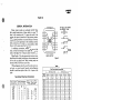
RECOMMENDED MAINTENANCE
PROCEDURE
If the timing or calibration of the equipment is outside of the field inspection limits given in the tables in
Part III, the equipment should be removed from the field
location and reshopped as directed in Part II.
Since traffic conditions vary so widely on different in·
stallations, no specific reshopping schedule can be generally applicable. However, all field units on an installation should be brought into the shop after the first one
to two years of service (depending upon the density of
traffic) and given a detail check and inspection.
The condition of these units as shown by the first shop
inspection will enable the railroad to set up a suitable
reshopping schedule.
The office line-coding units are subjected to more
severe service than are the field units; therefore, it is
recommended that the office line-coding units be re·
shopped approximately twice a~ often as the field units.
It is recommended that "Field Maintenance Tests"
be made at regular intervals as outlined in Part III of this
pamphlet.
5122,p. 1
WAIICD
~
PART II
RESHOPPING PROCEDURE FOR
INTERCHANGEABLE UNITS and
KP POLAR RELAYS
Office Line-Coding Units
Field Line-Coding Storage Units
Field Storage Units
Field Pyramid Units
GENERAL PROCEDURE
The following procedure is recommended for reshopping the interchangeable units and KP polar relays.
Detailed information is provided in the paragraphs following the tabulation below.
1. Connect unit to the Test Set and take cycle recorder
tapes as record of condition of unit when removed from
service.
2. Mechanically inspect and clean the units and included re:ays.
3. Check the electrical calibration of the Style "L"
relays.
4. Check the electrical calibration of the Style KP
polar relays.
5. Reconnect unit and KP relays to Test Set and proceed as follows.
6. Take cycle recorder tape to determine condition
of timing.
7. Make timing adjustments if required.
8. Recheck electrical calibration of relays readjusted
to obtain timing.
9. Test unit for operation on variable circuits as
outlined on Test Set diagram.
10. Test unit for operation on voltage limits.
11. Check operation of "CO" thermal cutout.
12. Take final tapes of codes for record of timing.
Sign and date the record and preserve for future reference.
13. Clean and seal the unit.
MECHANICAL INSPECTION OF UNITS
AND INCLUDED RELAYS
Inspection From Back of Unit
1. Inspect wiring of equipment and top plate for
evidence of heating or lightning shots. Test insulations of
contacts involved in the line circuit, using an instrument
which applies at least 100 volts between the contact members and the relay frame. A 500 volt megger is a very
suitable instrument for this purpose.
Insulation tests may be made by meggering between
terminal posts as tabulated below. A more detailed check
should be made inside the unit when the megger tests
indicate the presence of damaged insulation. All readings
should be infinite except the reading between terminals
41 and 42 on the office line-coding units. When testing
between these two terminals, the needle should dip to a
5122,p.2
low value at the beginning of the test and should then
climb upwards reaching a final value greater than 20
megohms in a few seconds. (Note that if an a-c. type tester
is used, a permanent low reading will be obtained on this
test due to the impedance of the condenser.)
When any contact stack shows evidence of breakdown, all the bushings and insulating blocks in this stack
should be replaced. Also, the contact springs should be
carefully cleaned to eliminate any trace of carbonized
material around the holes through which the bushings
pass.
Test as follows:
Office Line Coding Units: (Make sure R relay is in the
normal or clockwise position.)
41
42
53
63
19
20
to
to
to
to
to
to
19, 20, 42, 53, case
19, 20, 63, case
19, 20, 63, case
19, 20, case
20, case
case
Field Line-Coding-Storage Units
91 to 17, 19, 20, 71, 92, 94, case
92 to 17, 19, 20, 71, case .
17 to 71, case
94 to 19, 20, case
17 to 19, 20, case
71 to 19, 20, case
1~ to 20, case
20 to case
2. Inspect all connections for tightness and proper
soldering.
3. Inspect mounting of equipment on mounting strips
for tightness.
4. Inspect contact stacks to see if any are loose.
Inspection From Front of Unit
1. Inspect and clean relay armatures, cores and backstraps in accordance with Service Specification 3701 for
Style "L" relays.
2. Inspect relays for burned or pitted contacts and
check contact adjustment. With the exception of the
contacts listed below, it is not necessary to gauge and
adjust each contact accurately. On each relay one contact which meets the values specified in Service Specification 3701 may be used as a guide in making a visual
comparative check of the adjustments of the remaining
contacts. Each of the contacts listed below should be
.,
WRBCD
~
accurately gauged and adjusted. See wiring diagrams for
piece numbers of these relays. On relays witb nomenclature tags, the piece number will be found on the tag holder,
under the tag.
All BT contacts-Identified by black line on heel
springs*
All Continuity Contacts-These contacts may be
identified by their special construction.
506 SYSTEM
Office LC Unit-PC relay, contacts BZ, BS, AS and
CS*
Field LCS Unit-MSP relay, contact AZ (continuity
contact)
M relay, contact C3*
506-A SYSTEM
Office LC Unit-PC relay, contacts AZ and CZ
(continuity contacts)
Field LCS Unit-S relay, contact Bl (continuity
contact)
M relay, contact C3*
*These contacts have special adjustments. These
adjustments, as well as those for continuity contacts,
are listed and explained in Service Specification 3701
under "Special Contact Adjustments".
STYLE "L" RELAYS
,..
The Style L-1 and L-3 relays used in Time Code Control Systems are direct current neutral relays. Style L-1
relays are equipped with a "round" armature and are
ordinary acting. Style L-3 relays have a "square" armature and a double magnetic circuit and, therefore, are
adaptable as slow release relays when shunted by a rectifier. These "square" armature relays are employed
principally for code impulse timing.
These Style "L" relays are housed in groups in sheet
metal cases. Those groups used at the field locations (field
line-coding-storage units and field storage units) and the
group in the office which is common to all the stations
(office line-coding unit) are plug connected for convenience in changing out the units. Generally, the individual
Style "L" relays are not plug connected.
There are two methods of designating the relays in
the units as to nomenclature and piece number. On relays
built prio: to the middle of 1945, the nomenclature was
stencilled on the front of the armature. Relays built
since that time carry a separate nomenclature tag fastened to the front of the relay. On these relays the piece
number of the relay is stencilled on the tag holder and
may be seen by removing the tag from the holder. In
both cases. the piece number of the relay is stencilled
on the relay backstrap below the contacts. Also, in both
cases, the piece numbers and nomenclatures are shown
on the wiring diagram for the unit.
Calibration
Style "L" relays should be repaired, readjusted, and
recalibrated when necessary in accordance with Service
Specification- 3701.
STYLE "KP" POLAR RELAYS
The Style KP relay is a polar direct current twoposition relay. Two differently operating types of relays
are provided; namely, "stick" and "biased". The stick
type relays are operated into alternate positions (normal
or reverse) by opposite polarities, and the contacts remain
made in the last operated position when the coils are
deenergized. The biased type relays are operated into the
normal position by normal polarity, but the contacts
return to the reverse or" biased" position when the relay is
deenergized and remain in that position when reverse po·
larity is applied. Thus the biased relay functions similar to a
neutral relay except that it will operate on only one polarity.
All KP relays are individually housed in bakelite
cases, with all operating parts fully enclosed and sealed.
All contacts are visible through the front cover glass.
Contacts are moulded in bakelite, and the contacts are
of silver to silver multiple button type. The field line and
starting relays are the biased type and have two normal
and two reverse independent contacts. The contact opening of this type of relay is approximately 0.030". The
office line relay is the stick type and has two normal and
two reverse independent contacts. The contact opening
of this type of relay is approximately 0.040". The field
function relays and office traffic control relays are of the
stick type and have four normal and four reverse nonindependent contacts. The contact opening of this type
of relay is approximately 0.050".
All KP relays have two coils which may be used either
independently or in series to suit requirements. The coil
resistances vary with requirements.
All KP relays are individually plug connected for
quick and easy replacement. Means have been provided
in the relay case and plug connectors to prevent the
plugging-in of a given relay into any but the correct position. A combination pin plate is associated with each pair
of plug connectors. The plate contains five pins in various
combinations, so that each separate piece number relay
has an individual combination assignment. Slots are
milled in the base of each relay to match this assignment.
As a result, none but the correct relay, having slots matching pin positions, can be plugged into a given position in
the relay rack.
The ten possible pin positions are numbered consec·
utively from left to right looking at the front of the relay,
and the numbers remaining on the base of the relay after
slots have been cut identify the code combination for
that relay.
Reshopping
When the field inspection (see Field Maintenance
Tests in this pamphlet) indicates the necessity for it,
the KP relays should be reshopped accorqing to Service
Specificafon 3623.
5122,p.3
WAIICCI
~
If, during reshopping, the specified calibration values
cannot be obtained, or if any of the relay operating parts
(such as coils, contacts, connecting springs, etc.) require
replacement, the relay should be returned to the factory
for repair.
DESCRIPTION OF APPARATUS AND SET-UP
FOR MAKING OPERATION, TIMING AND
VOLTAGE TESTS·ON COMPLETE UNITS
Test Set
110
CABINET
TERMINALS
OFFICE
LC UNIT
v.{
A.C.
FIELD
LCII UNIT
5111-----u>----eai----t-i.·
Complete test set hook-up is shown on Drawing
02547, Sh.5, in the back of this booklet. In addition to
the test set hook-up, the drawing shows complete interconnections between test set and standard C.T.C. units.
A tabulated procedure for testing is also given.
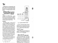
Cycle Recorder .
This instrument provides a convenient means for
measuring and recording short time intervals such as
code impulses. The two punch recorder gives a complete
record of a whole code on one tape. Odd-numbered impulses are recorded by one punch magnet on one line
and even-numbered impulses by the other punch magnet
on a second line, as shown below. When the tape record
shifts from one line to the other, chere should not be an
overlap of more than one perforation. (This overlap will
occur when the shift in the record from one impulse to
the next occurs just as the A.C. timing wave reaches the
point where both punch magnets will operate.) An overlap of more than one perforation, or loss of perforations,
indicates that the cycle recorder needs adjustment.
The tape record below shows a correct tape. In reading a cycle recorder tape, count each perforation as ~
cycle. Disregard the overlap punch in the count.
I
11
l!
...
l!
....
2i
41
ai
OVERLAP
l!
.... .... .... .... .... .... .... ....
2
3
4
5
.. .... .... .... .... .... ... .... ... ....
I
2!.2
1!
2
2
1
2
3!.2
3
4;
4
5
To obtain the timing in terms of seconds, divide the
recorder reading by the frequency (in cycles per second)
of the power source used.
When the only AC source available has a voltage of
220 volts, the recorder may be used by connecting a
1500 ohm resistor in series with terminal ex.
Cycle recorder tape is "National Cash Register Tape
Size C", Ref. 2, Plate T-575, or it may be bought at any
National Cash Register Supply Store.
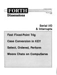
Cycle Recorder Connections
Figure 1 shows Cycle Recorder connections for
measuring the timing of units either in the multiple code
line installation or in the Test Set. The right-hand punches
are for odd-numbered pulses and the left-hand punches are
for even-numbered pulses.
5122,p.4
Fig. 1. Cycle Recorder Connections to Code Units.
In· addition to determining the timing of code units,
as shown in Fig. l, the cycle recorder may be used to
determine release times of individual relays as illustrated
in Service Specification 3701 under "Release Timing".
Adjustment of Cycle Recorder
If, after continued use, the cycle recorder gets out of
adjustment, it should be readjusted in accordance with
instructions in Service Specification 3688.
THERMAL CUTOUT ON 506 SYSTEM UNITS
After the unit has been at rest for at least 5 minutes,
check the action of the "CO" thermal cutout by repeated
coding (starting switch up) until the thermal unit stops
the coding action. This should require from 12 to 15
codes. Note that the unit codes again after being inactive
approximately 10 seconds, and transmits two or three
codes before again cutting out. This test should be mape
with the field battery switch set at point 16 (field voltmeter
should read 16 to 17 volts).
If adjustment of the thermal cutout is required, the
silver contact strips forming the contact of the relay
should be bent. Never bend the bi-metallic strip.
THERMAL CUTOUT ON 506-A SYSTEM UNITS
A. Timing Check Using Test Set
After the unit has been at rest (with CO de-energized)
for at least 12 minutes, set the field battery switch at point
16 (the field voltmeter should read 16 to 17 volts) and
check the timing of the CO by setting the line test switch
to position 4 and operating the field starting switch. The
CO should open its contacts in from 100 to 140 seconds
after operation of the starting switch. If the timing is
within these limits, no adjustment should be attempted.
However, if the timing is not within these limits, the CO
should be adjusted to open in a nominal time of 125
seconds. Adjustment should be made by following the
procedure outlined in paragraphs "B" and "C".
wAaca
~
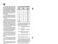
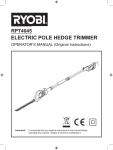
B. Contad Sprint Adjustment Check
To determine whether the contact spring members
have become misadjusted, place a small magnetic shunt
(such as soft iron or transformer steel-not more than
0.013" thick) in.the air gap across the permanent magnet
poles opposite the curved steel armature, both of which
are attached to the extreme ends of the contact members.
See Fig. 2. When the contact tips just make, there must be
a small air gap perceptible between the steel shunt and
the permanent magnet curved armature. With the shunt
in place, practically all contact pressure due to attraction
between magnet and armature is relieved and the silver
SENDING
PERMITTED
HEATER
ELEMENT
BENDING
PERMITTED
PERMANENT
MAGNET
CURVED
STEEL
ARMATURE
SNAP ACTION THERMAL CUTOUT
PLAN VIEW
Fig. 2
tips should have light barely perceptible between them.
In making adjustment to meet this requirement, apply a
bending tool to the heavy member which supports the
bimetal strip to which the permanent magnet is attached,
applying it between the insulating blocks and the first
rivets. Never bend the bimetal strips in any way. Check
to see that the silver tips meet squarely. Remove the magnetic shunt and repeat the timing check per paragraph
"A".
C. Timing Adjustment
,..
Make final timing adjustment, if necessary, by changing the air gap between the permanent magnet and its
armature. Apply a small bending tool to the straight portion of the curved steel armature, hold the contact firmly
so the bimetal strip will not be bent, and bend the armature toward or away from the magnet. (A very slight
change in air gap makes a marked difference in timing.)
To lengthen the time required to open the contact, decrease
the air gap; to shorten the time, increase the air gap. Allow
the full cooling period of 12 minutes before each timing
check. IMPORTANT: When correctly adjusted, the
curved armature must not come in contact with the permanent magnet at any time during operation.
D. Service Test
Directions for field testing of the CO thermal cutout
are included under "Field Maintenance Test"-Part III
of this pamphlet.
For Reference Only
If the initial opening time of the thermal cutout is
within the correct values, it will reclose its contacts in 100
to 145 seconds and will reopen them in not less than 60
seconds, provided the ST relay is kept reversed.
CODE TIMING
Short Impulses
A short odd-numbered impulse (line relay contacts
counterclockwise) is timed by the pick-up of a counting
relay, release of T, and the pick-up of R.
A short even-numbered iinpulse (line relay contacts
clockwise) is timed by the pick-up of a counting relay,
release of a counting relay, pick-up of T, and the release
of R. These values are in general fixed with the type of
relay.
Speed of Counting Chain
If all contacts are properly adjusted and the armatures
and cores are free from dirt, the counting relays will
follow a speed of about 24 pulses per second at normal
voltage. A test for the counting chain, as well as the rest
of the unit, can easily be made by varying the voltage as
outlined under "Tests of Units on Voltage Limits", Page
6 . If a unit will work properly with this voltage variation, ample margin is provided in the counting chain.
In timing a unit, it is an aid to remember that IL,
being odd-numbered, determines the length of all oddnumbered long impulses and controls registry circuits over
contacts on the odd-numbered counting chain relays
1-3-5-7. Relay 2L, being even-numbered, determines the
length of all even-numbered long impulses, and controls
those registry circuits which are taken over the evennumbered chain relays 2-4-6-8. In each case the time ~f
LP is added to that of IL or 2L to produce the long impulse
at the transmitting station. At the receiving station the
time of LP does not enter into the registry of the long step.
Conditions and Set-up for Checking Timing
When timing checks and adjustments are made with
the unit operating in the test set-up, timing shall be measured with unit sending codes under normal line current
conditions, local operating voltage of 16-18 volts D.C.,
and nominal temperature (70° F.). The procedure shown
on 02547-sh.5 should be followed.
Order of Making Timing Measurements and Adjustments
in Shop
If it is necessary to change the timing of any relay, the
air gap, stroke, etc., should be adjusted as illustrated in
Service Specification 3701. After making any timing
adjustment, the electrical calibration of the relay should
be rechecked.
I. Check the timing of the short odd-numbered im,
pulses. If necessary to correct timing, adjust T relay.
2. Check the short even-numbered impulses. If incorrect, check stroke and contact adjustment of relay T
and counting chain relays. Resistor R4 {in 506 system)
or T (B) (in 506-A system) can be inserted or cut out to
further vary timing.
5122,p.5
WAIICCI
~
3. Check the release time of IL and 2L. To do this
insert a piece of paper to insulate contacts A3 and C3,
on LP relay, thus eliminating the LP relay from the timing.
Check the timing of the long odd-numbered impulses in
last half of code (impulses 9, 11, 13, 15). Readjust IL if
necessary. Check the timing of the long even-numbered
impulses in last half of r.ode (impulses 10, 12, 14). Re·
adjust 2L if necessary.
·4. To check the release time of LP, remove the insulation from contacts of relay LP and check timing of the
long odd and even impulses in last half of code. Readjust
LP if necessary.
'
5. Time the interval between two consecutive codes
to check. the cascade release times of relays LB and LBP.
Consecutive codes are sent by operating code starting
switches upward. In the field unit, insulate MSP contact
C5 (in 506 system) or B6 (in 506-A system) to eliminate
relay SS for this test. If the time between codes is incor·
rect, readjust the timing of relays LB and LBP, keeping
as much time as possible in the LB relay.
To have office codes take precedence over field codes,
the time between control codes should be adjusted to·
ward the lower limits, and the time between indication
codes should be adjusted toward the higher limits.
6. Check that relay LB will hold up when the unit is
transmitting on 12-13 volts. If it is necessary i:o adjust the
LB relay to meet this .requirement, test 5 (above) should
be repeated and, if necessary, relay LBP should be readjusted.
7. To check release time of relay SS, remove insulation from contact of relay MSP and time the interval
between two consecutive indication codes with SS operating.
When checking extra field storage units, the only timing required is SS relay (count 7), using a correctly timed
LCS unit.
8. In units for 506-A system send a manual recall code
and check the length of the 9th impulse.
Table 1-Approxlmate Release Time of Slow Relaa18 Relays
Rela'
Nomenc ture
Approx.
Cycles Release
Approx.
Air Gap-Inches
T
4
0.012•
IL
11
0.002•
2L
11
0.002•
LP
6
0.015..
0.002"
LB
18
LBP
12
0.002"
SS
20
0.002"
PCP
19
0.002"
Office M
8
0.002"
When measuring the timing of units in the test set,
the various counts given in the Timing Table can be determined from cycle recorder tapes as follows:
Tape No. 1-Having max. number of short impulsesCounts 1 and 2
Tape No. 2-Having max. number of long impulsesCounts 3 and 4
Tape No. 3-Having max. number oflong impulsesCounts 5, 6, 10, 11, 12 and 13.
Tape No. 4--Consecutive Codes-Count 7A or 7B
Tape No. 5-Consecutive Codes-Count 8
Tape No. 6-Manual Recall Control Code-Count 9
NOTE: Where adjustments required to obtain correct
timing values for one test affect values previously checked,
the results of the previous tests should be rechecked to
assure that they are still within the specified limits.
For timing of the field units in the installation see
Part III of this pamphlet.
TESTS OF UNITS ON VOLTAGE LIMITS
As an overall check to insure ample margin on the
timing of the relays, operate the field on 13 volts, and the
office on 13 to 24 volts, and note that proper selections are
made. Then operate the office on 13 volts and vary the
field from 13 to 24, and note results. Use codes 234 and
678 for these tests.
5122,p.6
WA8CCI
~
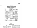
Table 2·Timing Table
TIMING TABLE-Time Code Control System Type L-Fomi1 506
a 506-A
Tllllat wlllt UIIIII Coaaected la Tai Sel-Tl•la1 In Cnla (60 Cyclu - 1 Second)
Tai Condlllont-Loal llotlery 16-18 V.-No•lnol Uu Current-T. .per&lure 70" F. Appn,x
Timing Limits
Count
No.
~thin
IMPULSES
its
Requires No
Adjustments
Retime When
Necessary
To These
Limitis
Operation to Obtnin
Timing
Measurements
Adjustment Required
To Obtain Timing
-- -- -Min.- -Max.
Min.
Max.
1
1J..5.'7-9-11·13-15 Shorts
4.5
6T
~
fl.O
2
2-4-6-8-10-12-14 Shorts
4.5
6.5
4.5
6.5
3
9-11-13-15 Longs (Without LP)
13
4
10-12-14 Longs (Without LP)
11
5
9-11-13-15 Longs (With LP)
Add 5
8
10-12-14 Longs (With LP)
Between Consecutive Codes
16 (Office)
Between Consecutive Codes
16 (Field-Without SS)
Between Consecutive Codes
16 (Field-With SS)
Add 5 to 7 to Count No. 4
75
9
9th Impulse of Manual Recall Code
57
6
7A
--7B-
10
No Timing Required
No. 1 Impulse (Control)
No. 1 Impulse (Indication)
11
3-5-7 Longs
12
-13- 2-4-6-8 Longs
57
59
---17
14
16
15
12
14
---to
7 to Count No. 3
61
58
58
Insulate LP Contacts
A3&C3
Insulate LP Contacts
A3&C3
Remove LP Contact
Insulations
Remove LP Contact
Insulations
Time lL Relay
Time 2L Relay
Time LP Relay
Time LP Relay
60
Time LB & LBP Relays
60
Insulate MSP Front
I.Jontact CS (or B6) Time LB & LBP Relays
Remove MSP Contact
Time SS Relay
Insulation
Operate Manual
Time Office M Relay
Recall Button
- - - - 62
60
63
----83
85
77
---- -61
TimeT Relay
Calibrate T & Chain
Relays
These Values Are For Reference Only
Add 2 to 4 to Count No. 5
Add 4 to 6 to Count No. 1
Add 1 to 2 to Count No. 5
Add 1 to 2 to Count No. 6
When Values Exceeded
Calibrate lL & 2L
Calibrate 1L-2L-LP
LB-LBP
Calibrate F-G-S
Calibrate F-G-S
PART 111
FIELD MAINTENANCE TESTS
GENERAL
At the time a unit is replaced, the operator should
make a complete operating check of the new unit to
assure that it is functioning properly.
The field tests for coding units outlined in the following paragraphs should be made periodically (quarterly
or semi-annually) to anticipate trouble before delays are
actually caused. It is also recommended that the maintainer make a periodic visual inspection of relay contacts
and operation.
TIMING OF UNITS IN SERVICE
(As Measured From Office)
The timing of a field unit in service may be checked
from the office by recalling indication codes and recording
them by means of a cycle recorder (with relay) as shown
in Figure 1. These recorder tapes should be checked
against the values shown in the accompanying "In
Service" timing tables. Note that there is a separate table
for "In Service" timing of field units on carrier controlled
sections when the timing is measured at the office. These
values must be used to obtain a true indication of the
timing of the field units under these conditions. A suggested form for conveniently recording timi11g data is included in the back of this pamphlet.
The timing values covered by counts 1, 2, 5, 6, 7A,
7B, 9, 10, 11, 12, and 13 in the table may be obtained from
the recorder tapes of individual codes from the unit being
tested. The· 16th impulse at the end of a control code
followed by a second control code provides count 7A for
the office unit. The 16th impulse at the end of a control
code or the 10th impulse at the end of a manual recall
code followed by an indication code provides count 78
for the field unit. Count 8, if desired, can be obtained by
having a second person at the field location send consecutive indication codes or can be obtained by taking the
cycle recorder to the field location and connecting it to
the field LCS unit as shown in Figure 1. Repeating indication codes may be initiated by removing the wire from
Post 42 of the LCS or S unit in question. Units are adjusted for timing at a temperature of approximately 70° F.
The timing will vary somewhat with difference in temperature. Therefore, timing records taken in service at
temperatures other than 700 F. should be corrected for
temperature in accordance with the accompanying table.
If a tape shows a unit to be outside the limits shown
in the proper timing table, two additional tapes of the
same code should be taken, and if either of them shows
the steps in question to be within the specified limits, the
unit may be considered satisfactory for service. Any unit
which these tests show to be definitely outside the specified timing limits should be removed from service and
reshopped in accordance with Part II of this pamphlet.
5122,p. 7
WAIICD
~
Ta'11e3
In Se,vlce Timing of Office Units and Field Units in D. C. Code Sectlons--Valuu In Cyclu
et Verlou1 Temperaturu (f = 60)
105° F.
Count
No.
15° F.
35°F.
0° F.
----
Min. Max. Min. Ma.x. Min. Max. Min.I Max. Min. Max.
3-5-7-9-11-13-15 Short
1
70° F.
- -- -- -- -- -- -
Impulses
4.5
4.5
6.5
4.5
6.5
6.5
4.5
6.5
5.0
7.0
---7.0
7.0
5.0
7.0
2-4-6-8-10-12-14 Short
9-11-13-15 Long
18.5 23.5 19
24
19.5 24.5 20
25
21
26
6
10-12-14 Long
16.5 21.5 17
22
17.5 22.5 18
23
19
25
7A
Between Codes (Office)
7B
Between Codes (Field-No SS)
24
18.5 24.5 19
25
20
26
8
10
No. 1 Impulse (Control)
11
No. 1 Impulse (Indication)
- -- -- -- -- - - - - -- -- . ..
. ..
. .. . .. ..
...
... 57 61
- - - -- -- -- -- -- - - - - - - 60
64
58.5 62.5 59
63
62
66
64
68
---- -------------- -82
74
75
77
87
79
89
92
84
85
-------------- -- ---...
. ..
. .. . . . . .. . ..
. ..
I_··_·~-~
---These values are for reference only
---------------- -. .. . .. 21 28
. ..
. ..
...
..
... . ..
- - --- - - - - - - - - - - - - - - - 8.5 12.5 8.5 12.5 8.5 12.5 9.0 13.0 9.0 13.0
---- ---- -----------20.5 26.5 21
22
28
26
19.5 25.5 20
27
- - --- - - - - - - - - - - - - - - - ...
No Timing Required
12
3-5-7 Long
13
2-4-6-8 Long
---------- -------- - - -- - - -- -- -- -- -- -
Between Codes (Field-with SS)
9th Impulse of Manual Recall Code
5.0
5.0
5
·9
6.5
4.5
2
---
4.5
6.5
17.5 22.5 18
Timing at other temperatures can be determined by interpolating values in the table above.
Table 4
In Service Timing of Field Units as Measured at the Office for Coded Carrier-Controlled Sections-Values in
Cycles at Various Temperatures (f = 60)
Count
No.
Impulses
1
3-5-7-9-11-13-15 Short
2
2-4-6-8-10-12-14 Short
5
9-11-13-15 Long
6
10-12-14 Long
7B
Between Codes (Field-No SS)
8
Between Codes (Field-with SS)
No Timing Required
11
No. l Impulse (Indication}
12
3-5-7 Long
13
2-4-6-8 Long
15° F.
70° F.
35° F.
0° F.
~·~
------------ ---Min. Max. Min. Max. Min. Max. Min. Max. Min. Max.
I
I 5.o
i 3.5
7.5
=
= -=-=== = = = . =
5.0 7.5 5.0 7.5 5.5 8.0 5.5 8.0
- -- - - - - - - - - - - - - - - 6.0 3.5 6.0 3.5 6.0 4.0 6.5 4.0 6.5
- -- -- - - - - -- -- - - - - 21.5 27
20
25.5 20.5 26
Jl9.0 24.5 19.5 25
- - - - - - - - - - - - - - - - --1
24.5
21.5 16.5 22.0 17
22.5 18
15 5 21.0 16
-----------------63
69
71
73
66
67.5
68
68
64
\62.5
- - - - - - - - -- - - - - - - -174
82
92
84
75
85
77
87
79
89
I
-----------------i These values are for reference only
r------------------13.5 9.0 13.5 9.5 14.0 9.5 14.0
I 9.0 13.5 9.0 - - - - - - - - - - - - - -.- - 22.5 29
21
:20.0 26.5 20.5 27
27.5 21.5 28
- -- -- - - -- -- - - -- -- I
116.5 22.0 17
23.5
17.5 24.0 18
24.5 19
25.5
Timing at other temperatures can be determined by interpolating values in the table above.
FIELD INSPECTION OF KP POLAR RELAYS
The field function and office traffic control KP relays
(105/105 ohm or 120/120 ohm stick type) should be
field inspected with approximately the same frequency as
standard relays (at approximately two year intervals).
The sensitive biased relays used as line and starting relays
in the field should have more frequent inspections. It is
suggested that they be inspected once or twice a year
initially and that the frequency of subsequent inspections
be determined by the results of these initial inspections.
5122,p.8
The office line relay is inside the office line coding unit
and should be inspected at the time this unit is reshopped.
The field inspection should include:
(a) Observation of the general condition of relay
operating parts visible through the cover glass.
(b) Check of calibration values.
If the observed condition warrants it or if the calibration values are outside the field limits as specified under
"Calibration", the relay should be reshopped as specified
in Part II of this pamphlet.
WIIBCD
~
C.libretion
SERVICE TESTS FOR THERMAL CUTOUT
IN 506A UNITS
KP relay calibrations should be checked in a circuit
similar to that shown in Fig. 3. The calibration values
If desired, the CO timing may be checked at the field
location under service conditions provided it is permissible
for the station to be inoperative during the time of the
tests. To check the CO timing under service conditions,
remove the field R relay from its plug connector for ·the
duration of the test, remove the ST relay from its plug
connector and, making sure that the unit has not coded for at least 12 minutes, replace it. The time from replacement of the ST relay until the CO opens its contacts
should be within the limits of 100 to 140 seconds, provided the field battery voltage is 16-17 volts. Under this
test the M relay will be picked up whenever the CO is
energized. Therefore, operation of the CO can be followed by observing the operation of the M relay.
CAUTION: If the installation is equipped with
"Field Station Disconnect", a jumper must be connected
between terminals 47 and 18 on the LCS unit plug connector. Also, the "Disconnect" relays (RP and RPP) will
be deenergized at the end of this test and must be picked
up by having the operator send a control code to that
station.
POTENTIOMETER
RHEOSTAT
SATTERY
Fig. 3
should be taken on each coil separately in accordance
with the accompanying tabulation on page 28.
The biased relay should first be charged at normal
polarity to approximately four times maximum pick-up
value and the current then gradually reduced until the
relay releases to determine the release value. Open the
circuit momentarily, and then close it and gradually
increase the current until the relay closes its front contacts
to determine the pick-up value. Further increase the current until the armature core pins touch the pole pieces to
determine the full-stroke value.
PLUG CONNECTORS
The stick relay should first be charged at one polarity
to approximately four times maximum pick-up value and
the current then gradually reduced to zero. Reverse the
polarity, then gradually increase the current until the
relay reverses position to determine the pick-up value.
The relay should go to full stroke at this same value. This
calibration should be obtained on both polarities, with
operation to both normal and reverse positions. The
relay should remain at full stroke when deenergized.
Plug Connectors are used on all of the code equipment
where interchangeability is desired. When removing a
plug connector from a unit, a small wooden pry about
Yi "xYi "xl2" will be found handy.
To inspect a plug connector, take an individual socket
or female member (or special test socket shown on plate
T 575-page 12) and slide it over each wire spring in turn.
If the spring does not seem to make good contact, insert
Table5
KP Polar Relay Calibration
Relays received from the U.S.&S.
Co. or readjusted in R.R. shop
should be within these limits.
Relay
Nomf'n<'lature
Function Stick
and
Traffic Control
Field
Rand ST
Type
Piece
No.
Pick-up
Relay Coils
Code - - - - Milliamperes
No. Location Ohms - Res. Max . • Min. Full Stroke
---- --- -- -Stick
Upper
217122 12347 Lower
- -- -------Biased 191481 57890
Upper
Lower
Upper
Office
R
1070
1070
5.2.5 3.7.5
5.25 3.75
-----------
Stick 231412 12357
!. 75
1.75
12.6
Contacts
------ -----Max.
Pick-up
55.0
55.0
6.5
6.5
Min.Relea.ci;e
--... ,
1.0
1.0
Type
Approx.
Opening
4
Transfer
0.050"
--- --2N-2R
Ind.
0.030"
2N-2R
Ind.
0.040"
--------....
..
9.4 +(Counterclockwise)+
75
(Clockwise)
20.0 15.0 +
+
15.6
24.0
+(Counterclockwise)+
33
(Clockwise)
29.4 21.6 +
+
23.9
--....
36.J
...
--- - - 18.9 13.1
Lower
...
6.5
6.5
taken out of serv-
ice.
Milliamperes
Minimum
Release
...
105 40.0 25.0
105 40.0 25.0
Values at which
relays should be
CAUTION: When calibrating KP relays, care should be taken to insure that no iron or steel is within two inch~s of the relay in a verti<'al
direction.
5122,p.9
WAIIC:a
~
the bit of a screw driver into the loop of the spring and
twist first one way and then the other. This will increase
the tension. The screw driver should be inserted in the
two loops, and not between the two loops in such a way
that they become separated. A properly adjusted connector should require a force of not less than 1 lb. or
more than 2 lbs. to remove it from the socket. If a connector is found to be faulty in any way, or if one side of
the spring loop is broken off, it should be replaced with
a new one.
When placing a plug connector back on the unit, care
should be taken to see that all of the wire springs are
properly started into the sockets before it is pressed into
place.
To check KP relay plug connectors, insert a metal
strip h uxy,; ux3 u into each spring slot and note that plug
connector spring bears against insert with reasonable
pressure, requiring 1 to 2 lb. pull to remove insert. A
faulty plug connector should be replaced.
PART IV
INSPECTION PROCEDURE FOR CONTROL
CABINET
OFFICE STORAGE UNITS
LEVERS AND PUSHBUTTONS
The relays in the Office Storage Units should be given
the same inspection as the relays in the coding units. This
includes mechanical inspection, contact adjustment,
and electrical calibration. Adjustment will be easier if
operating conditions permit the removal of battery from
the storage unit during test.
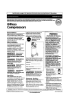
Contacts on levers and pushbuttons should have approximately the same adjustments as contacts on relays,
except that the openings should be as shown in Fig. 4,
CONTACT ADJUSTMENTS
Standard Levers
and Pushbuttons
FULL - STROKE
Push-Turn Levers
POSITION
FULL• STROKE
RELEASED
.005"MIN,
MID - POSITION
,040" MIN,
POSITION
POSITION
EF-tt~·;·tr··
.ooS"MAX ..
MID - POSITION
*NOTE: Contacts identified by a horizontal black line on heel spring loop
to be adjusted to approximately 0.010" overlap.
Fig, 4
5122,p.10
AUTOMATIC TRAIN GRAPH
At the option of the purchaser, the control machine
is equipped with an Automatic Train Graph which automatically records occupancy of ••os" sections, or other
information, on a continuous chart.
Complete instructions for the operation and maintenance of the train graph mechanism are provided in
Instruction Pamphlet U-5463. Copies of this information
are supplied with each Automatic Train Graph. (NOTE:
Instruction Pamphlet U-5463 describes and illustrates
train graph mechanisms manufactured subsequent to
January, 1946. Instructions covering earlier train graph
mechanisms are provided in Appendix I of Instruction
Pamphlet U-5121.)
w11•ca
~
PART V
GENERAL INFORMATION
KP RELAY
Relay contact stacks are numbered A-B-GD-E from
left to right facing front of relay, which in the type "L"
relay is the armature end. If a space for a stack is left
vacant, the space is lettered as if the stack were present.
Contact spring members are counted from top to bottom,
only the members appearing in the stack being counted.
Coil connectors are counted a'! a contact member, unless
they are in the same space with the contact.
In soldering connections, wireman faces rear of the
relay, so that his lettering is from right to left with "A"
stack at the right, No. 1 being top member of each stack.
Relay Racks:-The relay spaces of each strip are numbered from left to right, facing front, or relay armature end
of the rack or control unit. Relay mounting strips are
lettered A-B-GD-E-F from top to bottom.
Wiring diagrams show the rear of the relay rack, control unit, or control panel, hence the wiring diagrams
should be read from right to left with No. 1 space at the
right.
Table 6-Relay Wiring Diagram Nomenclature
Relay as shown
on Circuit Plan
r
Contact Arrangement
Rear View of Relay
c
B
A
Alu
ct•
Relay as shown on Wiring
Diagram - Wired Accord·
Ing to Color Code
!lli.:,_
~
C2
Bl
A2
Bu.S.
C3
B2
A3
~
~
C4
B3
A4
o.w.
s.w.
C5
B4
A5
R.Bu.
C6
B5
A6
o.s.
~
~
•coll Common
~
R.S.
~
~
Y.
~
....£:..
~
• •cou Control
Only the heel contact members on the circuit plan are
numbered and may therefore be identified on the wiring
diagrams by their positions as shown in the above example. A color code scheme is used for wiring, and both
solid and flex wire are used. Flex wire is identified on
the wiring diagrams by a letter F after the color. On any
one relay no two circuits have the same color of wire.
KP polar relays have their contacts numbered as shown
below.
On those KP relays which have independent contacts,
1 and 3 are normal contacts while 2 and 4 are reverse
contacts.
IH
KP RELAY AS SHOWN
ON CIRCUIT PLAN
ZR
+1
IP
+•s-·
-I
-z
+2
2P
-l=IP
IN
IR)
STICK
2
u
-2
4P
3P
4R
3N
SYMBOL
,
2H--i=.Zfl
~3P
3N
)BIASED
r-·p
SYMBOL
4R
CONTACT NUM&CRING
VIE.WtO FROM rRONT
Figure 5
Table 7
Field Code-Setting Connections
For Sending Codes
For Receiving Codes
Station Connect
Connect
Connect
Connect
Connect
Connect
Code
70
Poat 80
Post 45
Post 50
Post 60
Post 40
Number Post
to
to
to
to
to
to
Post
Poat
Post
Post
Post
Post
_ _7_3_ _ _ _8_4__ _ _5_2_ _ _5_3_ __6_4_ _
_ _7_2_
~ _ _7_2_ _ _ _7_3_ _ _ _8_5_
_ _5_3_ _ _ _6_5_
_ _5_2_
_ _7_2_
__8_6_ _ _5_2_ _ _5_3_ _ __6_6_
"""'Tao _ _7_2_ --73-_ _7_3_
_ _5_2_
_ _5_3_
_ _6_7_
__8_7_
~ _ _7_2_
_ _8_8_ _ _ _5_2_ _ _5_3_
_ _7_3_
--68-~ _ _7_2_ _ _ _7_4_
_ _5_4_ _ _ _6_5_
_ _8_5_ _ _ _5_2_
""""2i5 _ _7_2_ _ _7_4_ _ _8_6_ _ _5_2_ _ _5_4_
--66-346 _ _7_2_ _ _7_4_ _ _ _8_7_ __5_2_
--54-- __6_7_
247 _ _7_2_ _ _ _7_4_
_ _5_2_ _ _5_4_ _ __6_8_
·--88-248 _ _7_2_ _ _7_5_ _ _8_6_ _ _5_2_ _ _5_5_ __6_6_
~ _ _7_2_ _ _7_5_
_ _8_7___ __5_2_
_ _5_5_ __6_7_
""T57 _ _7_2_ _ _7_5_ _ _ _8_8_ _ _ _5_2__ _ _5_5_ __6_8_ _
~ _ _7_2__ _ _7_6_
_ _6_7_
~ - __5_2_ _ _5_6_ _
~ __
7_2_ _ _7_6_ __8_8_ __5_2_ _ __5_6_
_6_8_
:iiis _ _7_2_ _ _7_7__ _
_8_8_
_ _5_7_ __6_8_
·
~
~ _ _7_3_. _ _
_ _5_3__ _ _5_4_ __6_5_
7_4_
_ _5_3_
_ _7_3_ _ _7_4_ ~
__8_6_
---66-346 _ _7_3_ _ _7_4_ _ __8_7_ __5_3_ --54-_ _5_4_ _ _6_7_
247 _ _7_3_. _ _7_4_ _ _8_8_ _ _ _5_3_ _ _5_4_ _ _6_8_
346 _ _7_3_ _ _7_5_ _ _ _8_6_ __5_3_ _ _5_5_ _ _6_6_
~ _ _7_3_ _ _ _7_5_
_ _5_3_
_ _5_5_ _ _6_7_
__8_7_
~ _ _7_3_ _ _
_ _6_8_
7_5_ __8_8_
_ _5_3_ __5_5_
358 _ _7_3_
_
_
5_3
_
__8_7
_
_
_ _5_6_ _ _6_7_
·--76-""'aii7 _ _7_3_ _ _
_7_6_ __8_8_ _ _5_3_ --56-- --68-_6_8_
_ _7_3_
_ _7_7_ _ _8_8_ _
~ - _ _5_7_ _ _
378 _ _7_4_ _
__8_6_ _ _ _5_4_ _ _5_5_
_ _6_6_
-7-y;-~ __
_
_7_5_ _ _ _8_7_ _ _5_4_
_
_6_7_
7_4_
__5_5_
'""""i57
_ _5_5_ _ _ _6_8_
_ _7_5_ _ _8_8_ _ _ _5_4_
--74-458 _ _7_4_ _ _ _7_6_ _ _8_7_ _ _54
___ _ _5_6_
_ _6_7_ _
467 _ _7_4_ _
_ _5_6_ _ _ _6_8_ _
--76-- __8_8_ _ --54-458 _ _7_4_ _
_ _6_8_
_7_7_ __8_8_ _ _5_4_
__5_7_
478 _ _7_5_ _ _7_6_ _ _8_7_ _ _5_5_ _
__6_7_
567 _ _7_5_ _ _7_6_ __8_8_ __5_5_ _
~
_5_6_
__6_8_
---mis _ _7_5_ _ _ _7_7_ _ _8_8_ _ _ _5_5_ _ _5_7_ __6_8_
~ _ _7_6_ _ _7_7_ __8_8_ __5_6_
_ _6_8_ _
--57--
---m-
-m-
----m-
tffil
When field pyramid units are used, other code-setting
connections are required. These are
given in special drawings.
5122,p.11
· WABCCI
~
PLATE T-575
QQ
~
Q0Q) Q) Q
Q Q Q Q)
0
e;
0
QQ
Q §
0
12)
A
~
3
2
5
4
u_E---J
G
~
7
8
=10
14
c
=II
0
f
rn ~
19
Ie
26
13
34
28
s-
29
$
@
36
31
cc=========::::::J:J
30
===
~
32
CYCLE RECORDERS. TOOLS AND SUPPLIES
5122,p. 12
WAEICD
~
CYCLE RECORDER, TOOLS AND SUPPLIES FOR MAillTENANCE
Order by Plllte, Piece, Reference and Abbreviated Inscription Gh·en in
Heal')· Fatt Type: Only
UN102949
A
B
UN2316'18
c
17
DOUBLE PUNCH CYCLE RECORDER (Wlmn ordulng state installation
for which requ.lred){Uaed With 18 Btep 504 Time Code Systems) ••••••
C-9299-3
SINGLE PUNCH CYCLE RECORDER (When ordering state lnstallaUon
for which requlred)(Used with 14 Step Time Code Systems)•• , • , • , ••
C-9299-1
DOUBLE PUNCH CYCLE RECORDER (When ordering state lnatallaUon
for which requlred)(Uaed with 18 Step 606 Tlme Code Systems) ••••••
RESIN CORE SOLDER (or making soldered connecUons (Do not use acid
core or acid soldering paste or Ouid). (Not shown)
lBUOfJlOO 18
ANVIL (Used wl.th eyelet Rivets to attach Armature Bakelite to Relay
Armatures) (Not shown) •••••••• , ••• , •••• , •••••••••••••
A-2588-34
UM243028 19
SOCKET !or adjusting Spring Tension of C. T. C. type plug Connectors
A-2588..00
UM244'133 20
PUNCH, Used With Tubular Rivets to attach Armature Bakelite to
C-9299-4
Relay Armatures, , , • , , , • , • , , ••• , , • , • , , ••• , •• , , • , ••••
A-2588-72
UJ3982G
PLIERS POR REMOVING LAMP CAPS
U0245029
20.
PUNCH AND ANVIL SET (Includes 1-20 and 1-21) ••••••••••••••
A-2588-72
0139864
OFFSET SCREW DRIVER tor Nmovtng Relay Armatures
U0255804
20b
REPAIR SET FOR RELAY ARMATURES {Includes 1-7, t-8, and 1-20)
A-2588-12
ANVIL. Used with Tubular Rivets to attach Armature Bakelite to
Relay Armatures ••••••••••••• , • , , , ••• , , •.•••~ •••••••
A-2588-72
ROLL SIZE "C" PAPER FOR CYCLE RECORDER (10 per package)
UM164375
•
BENDER {OFFSET} tor Contact Sprlnga •• , , • , , •• , , , •..••••••
A-2588-15
UM2738J9
7
SWEDGE AND TWISTING TOOL for AdJusUng Relay Armatures •• , •.•
A-2586-95
UMI64:393
8
UJ39069
ANVIL for Adjusting Relay Armatures. , , , , •• , •.••••••• , , , •• ,
3/8'' ELECTRIC SOLDERING
10
11
llR
UM2H732 21
23
6" LONG-NOSE PLIERS {Not shown)
24
5" DIAGONAL CUTTINO PLIERS (Not shown)
25
3" SCREW DRIVER (Not shown)
A-2583-78
m.oN WITH STAND
NO, 22 B. &: S, GAUGE SOLID COPPER WIRE in color code for wiring
control machine and control unlt.G {Orders should specify quantity and
color desired}.
NO. 20 B. &: S. GAUGE FLEXIBLE COPPER WIRE 1n color code for
Wiring control ma.chine and control units (Ordera should apeclfy quantity
and color desired),
NO. 22 B. Ct S. GAUGE FLEXmLE COPPER WIRE 1n color code for
wiring control machine and control units (Orders should specify quantity
and color desired).
UN259500 26
KEY AND CLAMP tor compressing Spring on Push Turn Lever, ••• ,
A-2588-82
UM1'10241 28
KEY for Push Turn Lever a.86embly •• , ••••••••• , •.•••••••.
8802-06
UM282051 29
BENDER (Right Hand) for Contact Strips , , • , , • , ••••.• , •• , , , •
A-2588-108
UM262634 30
BENDER for Thermal Cutout ••••• , , • , •• , , , .•• , ••.• , • , •••
A~2586-84
UM243059 31
BENDER ror KN and KP Relays •.••••••••••••.•.•••••.•••
A-2586-68
UN320728
32
SPRING TESTER for LP-53, LP-58 and LP-70 Relay Bases •••• , ••
A-2588-39
PUNCH (Used with Eyelet Rlveta to attach Armature Bakellto to Relay
Armatures (Not shown). , ••••••••• , , , , , , • , , • , , • , •• , ••• , ,
A-2586-34
UN243000
33
ARMATURE POSITIONING OAUGE for Biased KP Relay (2 Required).
A-2586-65
UMl'l7B03 13
TOOL for removing Lamps •• , , , , , • , • • , , , , , •• , •••••• , , •..
A-2586-21
UN243001
34
ARMATURE POSmONING GAUGE for SUck KP Relay With 4 Transfer
Contacts (:!; Required) •••. , . , .. , ...•••••.• , ••..•••.••. ,
A-2586-65
UM172481
BENDER {STRAIGHT) for Contact Spl'lnga , , , , , • , , , •.•••••• , ••
A-25b6-14
UN243002
3S
ARMATURE POSITIONING GAUGE for SUek KP Relay with 2N and 2R
Contacts (2 Required) •••...• , ••••..••••.•.••••.••••. , .
A-2586-65
0139720
36
TUNING WRENCH for carrier Equipment ••••• , , •• , , .•••• , ••
A-2586-105
UM108099 12
14
Ul82103
15
GRAM GAUGE W, E. 68B for meaauring contact preasures (Not shown)
U139892
18
BURNIBHING TOOL W, 1::,265C for cleaning contacta (Not shown)
5122, p. 13/14
WABCO
~
OFFICE UN£-OlmNG UNIT
.l[1lI !rr='
romcc
:
II
BATTERY SWITC'!
:! Ill
I
oiotawMqau2a.
..I
.ti
I
;:
n
I
)
a
a I a
I
1sl
c:a
'
,a
J
-
I
I
•~·.:,.·_ _ ••Pl
_ , 1} l
ieo•l
~I!!
o•
it
I
I
TS
aft
@-c
'°~
STEP •• , .
TO
:::,o. "
I
>•I
;,..-.,,
STEP 14 , .
I
•,
I
I
---r
~,.
,:a.•
Hl-----f.U
l
1::
1 :---("
if r '
ul
I
•l•jt.
~
II
,
'
I
;
l
u
r----111
r;:::::j;:
j J.
LG
"
c~t"
I
I
INDICATION
STARTING SWITCHI
•
I
IIO
~
LINE
c1::~T
I
1
~ ·..
!
4
SW T
1,.CI
•r--1"
:·1--1-:
I
I
II
I
Pa~U·SW. Thefollowl111os-rat1ona1cbects ahould btinsdtlltertlfllltbalbtuptOfltfl7 Ucn.edandldjV;sled.
I
'"
I
°"""'
,. 0-nlCtRW.itl'eata
Bat 00:tce StatkXt 8elecUoR 8wttdlea to Hf.
Set Fiald BtaUoa S.m:Uon s.udle• to 3U.
Thl"X"nb.1tnthtcfflttlillmlld
Opt"rala lo lDtema;,t the code.
lltpHt~wtlhtleldoetlo14G.
SameuaboYt.
8tt.Offlutlstttr,fhrllchlopo11lllcllll4ud
FJtld 8sUtrt SwUd1 lo polltllcm 14 and chttk
that ofltce ,mU tnumttl and rCCeJ'fff complete
code• Oii •tsUan HltlCt:loml HT and fU. Thea
s.=tufortelttwlthOUlc:tClttlrtl
TNtBwitchllllhetl~
(•l
(a)(b) TSRab.JCtr-
I
I
~----l-.::::::.~.::.-.::.::-.:::i:.-.::.-l:.-.:::-.:=i
for ltll eUp.
l•l
Oleck of"&''
p&ck
f. OpnaUcn a vdtq:e UlllltB
ro
Owdl.clcurttr
Id
Owclt of
Q&ed: of
11t, SnlMdlllll.111W91.
(b) "TS'' la=, 1bowd rndffl dult.
tton 8. TnumltatolruOludanlndkatlua
le) Offkt THt limp POl!ld bt llpted .'
coaUiwo,;uityuce,tdllrhletbtltll.
•tepcfcontrolcodl.
(d) Place omce Cl«vlt Tut hltdl lo po3t•
Id) Off!u Tt$t l a = , ~ btlipt,td
Ol'lletllllttplltladlcatloncoda.
.....
IQ
Plac:t Offlct ClrC1.dt Tut lwltch to po111U011. If. Pia« Uni Tut Bwitcb to JIO'IIUOII.
LIM blffder
(I) CMckofR loektllc
UldnNUll!Ccll'Cldta
ObNnt u.t Qt 1.Glc"" ttmcu. s-flttma WDil ls lllamlMtd.
,_
Traumtta ecctrolcokwllll ft!! atepshorl.
Obmene lhll Ule "1Rlorl" hnld1oa po.
ttucalanlpl!lllkffllllltated.
Reput abcn• tests fer atept, 10 to U bchl$1Q.
&1-uabioTefwhta-....
Fu:t:Um lad1nUC11 lampl stlol1d bt
Upttd wbtlltkelr ( O f f l l ~ ladlcaUoa$leps lll't lcac- TlwJ &IWll1ld
...,..
Trusmlt tadkulca codea 111Wl J\mcu.oa. bd.1catlM S"1tdlea pa&tUcad fer
aad lllcrt
_,,,
tons
nlllll#darkwbelll1,1t,1,atepaanc!lwt.
Set Office 8a1UrJ Sdcb W pmUm 14 Uid
Fkld Batter:, h1tch to po$ll1Gn 24, ctteck tut
field -« traaellla aad rllHlff:a ccm;dete cod·
U011lltltleanlettlolul:SS1ud4G&. Set<X-
--
Batt.Hy 8..SICb to poslUOa If. Cbect ttw (hid
lffl1t truamHa and rKdtt• compWtt codla O<I
lltaUollulecU. . H'l:tM«a.
~measlorfi.
ti. Cem:tol Code Pnfarmce
Set.Lln1TtatS11'lkhtol!lellipoc11Uol1. Trua-
Tbe ''Cir retaJ ZhGodd pd!; ap 11111 Ult
tlratatepto1Alan'11pttbtcok.
,. JtatkA Lodcmt ctn:ult
s,t LID&TutBwltchtopoa;ltlollf. Operau
imtaalndlutl<lllcoda.
..... ...
ObNr"ltO;alfHlld""Y"nta,cutlOl
lts plq
COIICICClot. OpentellltFtttd~S1Plldt.
(b)fftlhdt.
-·
laJC!&tcllt11atU1t"C0"11p1r1U.
UmebusplClfl9dblU-'1U.
(b) Oper11te the Fhld !UrUa& Swttch to lllt up
poaltton.
lbl Cbeck that th& pntper lallllbtr d
COdH &H traum111.ed U epccUJtd hi
(1)S.tSU.Um1atlecUoa8wtk:ltestoGT8. Stt
(l)Tltt 51 lallllpsbouldfltdtoallh
Ftekl Clmttt Tt6t Swtkh to thl 18 po!!IUoa.
atep d all codes. Tbe Fiald Tfft
tamp should bt Upttd
&UI GlfP d
i.uc.ueacode..
U-ilU.
10. GffitralCtm.altT.sta
(a)tlS.l«:UCaClrw11
If) OfflctTutlaapabouldbtllehtecl
onHlhttepcfCOlllrolcock.
(cJ 0 '£.. pklr.upclrrult
forP,r1111.ldU11u
(c) Stt Fltld Clrwlt THI httdi to pomuon $l.
TnasmttcontrolandlNHcsttonCO<s.
le) Fleht THl lamp 00\11d li&M OR
llltfflpdau,codt.
Cd) .. A"and"B'"back
(d) Sit Field CkClltl THI htkb to posltlona H
aodUIIIWm. TrlMlnllccal.l'olandlfldka~
Uoncodeslllochcue.
{d) Fa.Id Tell Limp "'3u1d 0.... du.-~
P,ramidUflU1Ttr111.Gl)
(e.lSttl'tetdClrwllTHth!.tchtopos:lttoll63.
Tnnsmtt cad.NI a.S tadk.Uon codes.
l•I Fltld Tt1t Ll#lp s1u11W:1 flub oa
tlrst1UllollMl«U(l(lat4"PrJIUJcode.
Ctlpt"stklr.clttullf«
P:,nrnldUlll.l(Term.UI
(f) Sd field Clreull Telt &~tell to ,=Ilion ff.
Tnas1111tcW1trol1Dlllndk1ttoncodea.
(fl Tbt Field Test WQJt ahwld bt
Up.lid nctpt dutl"I Ult first natl•
Hlcct!Oftatqi.
ConMCtastorqa11111ttotht1tst1tl,ffll111tt
Sa.1Mulor2f;lldJ,bo!re.
(bJ Off!u Tift lamp ahWtd bt Upted
dulllean,codt.
Ill Place lhtLI.. Tfftawttch lnpltioll 1.
Tnumtt CORtll'OI coch. Nola: UM THI
Ill Note that tu fttld U1tt rtla1 N•
malM flMlql.Ud durlnr llllll ltd.
and
(I) RtmGH the field ''R.. relaJ f r -
C.8.ualtoper.a\Htomtf:rrupttlle
(b) Set Fltld Circuit Tnt Swttdl to plmUOft SI.
lb) Plac:tOfflCIClrcuttTHIBwikhtoposl~
Hoa H. Tnaam.lt codell.
t
II. COTtmkte
{I) 50GA UldU
NottU..t "CV tthJ111UltUe1dt..
SttatauoaSelec:Uoe&trrttcblll;dfkt to SH.
l'ltt&tlUoaStl~ Switch lllfltld to,.. ••
T:r&11.1U11lt111b:ldlcaUollcodt.
for Py,amkl Ulllt
{s) OfflctT1111tlaaplllwnldbtu,hted
dllntll«llltrolcodt.
Open.Ill Liu THt8wttch topoelttOII
l1Dmadlalal11*cktopoalUanJ.
S...utort.ellltl{wl.UIOffluCtr.
C!dtTestlt'WlldllaposlUGllll)
(b)M8P-lr.cOlltaet
l0po$t:S8
{c) P1ac:tOfflceC11'C1111Tfftswttdltopoc1IUon 51. Tnntmlt Cocltrol code.
Ul
............
U&fMd
I•) Offlce Tt•t WOp abou1d bt
m1ftnt1tepof1AJ~.
Pc.UIOIOO.L.C. IDllto. TotHtPi:.fflH'l
Ot' Pc.Ul1ta 0. L.C. mdla 1111111 '111.fflW M
,llcl1fflC01111eet&jaaperbet,.,_pooto42and
llllfortlllatHt. Tall1Ntawtndp1:r'1a111
"A" wllllffl Pc.lffllTorPc.UITffuallll
wtthl:Nlut.rclhe~rbl.ltwUtnotcom.p.lttalymtPc.1HOI0111dla.
T1w•
...
()pent. Fldd Fadtoa Coatrcl httch t.tbt 9
~ c a . TnMmlt a c=trol cokl 'tltth tbt tlh
Operate Liu BatltrJ 8.udl lo pcolUOD 2 &lid
reptat teata Uated 1IMff -4 abo"la.
I. StatklaEllm!AUoaClrcvlt
(I) "TS" lamp aboulcl flull Oii Ult
TnMadtlmticallclftcode.
ltl Plac•Offlctett'cntTt.t8wttrhtoposlTnntmltCOAtrul&llidffldlcatloff
Y mlM
Tffth1tclltotbt1Gpoattiaa.. Traumlt«.
trolMtlibidleaUoacodts.
UaUplcb11p. ffolaUIUUU..cadd
Nd! t.UcaU. - - tbt Office Test
$. OptraUCa cm lf1P LIM
c"""'
(c) Place Office CIN:Ult Tut lhr:Udl to poot-
,tloa11.
updrClltt
'I --
llf'
--
D<l>lCATlOM
HOl.tt.hatatUllandalndlcc:.uol
nde, the tH nlq IA tkfftld L.C.B.
ttc, BattillrJ hUdl to posWoa Ha.ad hid
Bwitchebailhtbllwtfldulhow,ilolHI
,..F..I
c-.
s.~ton.otflmdlaa
(bl Tra1uuz1Jtcoatroleode.
UOll 16. T,..._lt UI lfld!UUon code.
dreatt
..............
Set Stat1s Be1ecu. hUc:las lo Ut, H$, 4U,
Hf ud '"' 1ll 1NqH111C111. set OUlce Ctn:dt
Flc!d SbrUq bl.tu.
""·
ffd&&lanla7
(dJ ClleckoCdeliYlfJ
CGl&Wta OD T Hlt1
I
tsl
,"
~
a and
ev.lttbtdt
(c) ChlckofSTnlaJ
CUdcclrCllltOffr
nno LDIE-CODQIG-STORAGE mars
°"
Tr.uamltCO!lltrolardtDlllcsUoacoie-.
CO!llac:lclreulla
(Tums.8tQIIIU)
(a)""G"plclr.upclrcultfor
11. Chcct.dSIMapUllltO,.r-
atu,cClmlllalllL.C.8.Urdt.
Tnum.1tantadlcstt4acGdt.
(IIJ Fkld Circuit Test taR!p sbGrlld bt
llpted «alttlluoualt _ , . "'-""Ill& ladkllUoa codts.
lllgallcodtawtths'llltclllaalUltrpollUoa.
SelecUoah1tctlto"S'"1ndreputttsts21nd3
abowt.
UI The office "R" nlaJ lhooald cptr-
att ...-,arae leollllltr cloc:kWllle) ud,
alt.ttappC'Odlll&te17-IKOl'lll,Nhlm to thl flOl'mal. (dock wtM) po11l-
~m.
tt) a.ck cf lluut ne&U clradtl
00 ()ptrat1ControllW'tlfl1.s.t.tcbandh·
call lklttaa. 1lmwwtl(IWlly.
(k)NotelllalGlll1lOMeplluft1Wcontrol code
tnulldtltd.
ar•
!108...4.llllltaoal,I
I
I
I
I
f,_
... ,,
I
I '!Iii!
CIRCUIT DIAGRAMS FOR_$00~0U,
OPPA'ffllO TS8'ID TOR 11£U) 8TOllAQZ UN1T8
ConmlcllDtl>Telts.twttbL.C• .ndL.C.S.thlitaaad,cN,ttkla1Wltdla•fflaccordlnat11lth~l,J,J
sad4'&111Str "0-nl". 'l'hea npnt Tua J, 31, 4, 5 Md IGb ~ -
RI
"r
...
l'uct1aa1DdlcaU11111 Lamps 1ltll bll
llpted WUll their cornspcmdlq code
ffl'pll an laac- ntf reJllaa Upad
wstlllhieudcftbcode.
Opente LIM suttrJ Swttch to pooitioa
repn.tte.stsunder$.
-tac:t(Term.H)
}A.nm:
-.-l ..
---
8&lM u
Tramm1t tndk:&Uca codu wlth FaeUon la.lollC I.ltd abort
-418.
e. OpuaUoa.onfflpt.1-
' Ill
"1
I
I
otre.netb&ttbe"acrt"Fll:tlion
0
u,
I
tua tb "Llme'' F'ai::Ucll
PcsltlclllLa.mpla lU:wnlmted.
Qbff,u
~ ~ u . s t s f o r attp tOto 1$1M:lulve.
I
I
z.~d.fmlctlm
Ht0fflct8UttrJBWltebtopo11UlC1112flJlld
Ft.ld Battl17 Bwitch to poliUm 14 ud ap.tn
dleek tut offlet imtt tnltelllla and re«lfta
CGmpltttcodelon.utlalNlcctlcM ffle;nd
(b) aldtalLBRfroat
R?
rl"
--Yo
........
Ctffltact(T.rlll.11)
Ira
J
...... ._.
Tnulldt ... ~ eodllt.
$. Optt&Uoa oa Vottaa•
I
'"
codelMHOrala7bdr.lfleldL.C.S.
lmllptcbap. lfotel!o.tattbtmdof
eadl.ladli:aUcllcodttbtOfficaTeat
I. Tn.lllfflltCClfflOltode.
(rttumUuTtst8wltchtoJIO'lltlon3)
II
I
I
wJ
Hoqthatattbtdufadl:ccctnil
PoeitlolllAmplalllwn1uted.
dlallon Swituta ~tloud b,
nfltdrClllt
I
I
'..
thtlrNp!IUttdlort.
n .. .AU111Utsllhorddbttlmtdaadadjll1ltdllla«(lfdancewtthln$trucUon
f
I
I
••
I
f
1
I
I
•o
I
11 ••• Fllactloa Jadkatl• t.u,ps II to 1$ wm bt llhamiuttd -.hen their corn1pGl!dffll lndiuUon code atepm ua toac- The, wtU nmaln duk WMa
I
f
I
10••• FtmCtlon reU, SR opeutt• on altps II to 15 rA' Control code•- TU
pultculu llttp beffll hated must be selected bf GPff•tlnl tba Funcllon
Control Swlk:b totbt pcralllonc11rn11j)O:Odln,: wltll lbe step l'lltmtN!r. 1bt
rel111 bcipenttdlOtbtrenrH poatuoabp a kmt: trnpdseand totht
normal ,oollloa bf a AMI IIOpillff. n , fll!ICUOII potlltoa lamps tndtca1t tht posutoa (norJ111l 11r rr1arN) cf tbt rcta,.
,4-----t.-i
11
..........
l. ftece;ltlaa of Fu,cUoa 111-
u,
I
TnnamUacc,:tfficode1'1tbStll
Tn.ulDttaccatn:ll code...uh 9tb ctep sltort.
wtUI tht polilloas cf (Ill, l'IIIICtim Contr11I Swttcbe•- n ... code ateps
wtU be l q wtiea their respcethe swltcht•
to the dpt slld •m bt
ahortlltteilUitlrretpccth,n,ltchHUttGthtteft,
•+---i"
,.
I
I
°""""·
9poaltkDD.
U1tcorreJl9l)IICllncst11rtlnsnitchtotllt""llp""poslUc!:I.
:::::::::1::
I
:---J..I::
s
'
UNIT SELECTION
t ••. CoaHCUUft control ot ladlcsUca code• may be llllUUecl bJ 09ff•tlnl
11•. .tlldlnUoa code steps (or fancUca ladlcaUon are l q ar short m IC·
corduce With tht postucu cf the Fum::tloa lndtcaUO'III Sa'ltcbn. Thete
coJt •teps 111111 be 1q 1ffltn their rfllpeclh'e nrl.tchc!a are to Ult rl&fll
ud Will be ehort W!Ma thtJr rffpt(UH Swtk:hH SN toUle ltn.
J
ts
'
,t--------------------------
I
Opentt FttW ~ Co:luol Switeh to Uw
2.~(lff\:DcU(D
flldllelds!louldbeleltothtumtd!t:ll•.
o.•.Coatrolcocltatepafot"functloac<mlrol1reloncor llho:rtlna«orduce
n
"13
--
azr,d bld1m1cn codM.
4.CorSeDtlqreemc,it
~
I
S1ritd:11.DU1116po11ltkm. TnMmltcoatrol
L-TUT
...CATlllN
S.tStatio!a8eleet!GnS1i'tlchuloH8,H1ud
4 H h l ~ S.tOfflceCh:cvit.Tnt
Selectton .siritdt should be HI to qrtt with the tJpe of Wilt betq
$ .. .5ut:ltcontrolorllldlaUmcodtsraaybetnUtattdbymoatt11taril7cte.
,.-es.wict11aco:rretpc,,dlq&tilrUqnrttch.
;;1--1::
nf----fu
l r.=:t:'
l
...............
TB8T
I. Bbttoa.S.llcllm
$ •• .SU.tt..Selccttonnrftc\e11forboUloflktandfleld&MllldbeMttothe
detlred staUon call number. Ulllen Gtltenrlse •JJl!CU!ed. both otnu
a4------i'•
I
I
tt---fn
I
.
tested.
ii"
::~
n.
f; ••• Untl
ui-------;,•
:,----:,
I
I••
.i,t--------11,
s •,
....
.........
:,>1-1n
ae-
~
CtrcvU Test (OUke)
ClrclltlTtst{FJtldJ
•t----ti-
!Jr§'
·:
1J '"
•:a
~
!!!!£!
OffktBl.UetJ
FltJd&attary
LIMlbt1trJ
C?.NNECTIO~·
•
~
3 ... Extpt """' t!Ulerwlff apccUJtd, au usts .fhocld be ia:ade wtlh
ltctor .-.ttcbts Ill; pooilloas called for belC11J.
MULTIPL
1,.
.. ,t----i.,
· ~ ,u
iJ11
1::
: I r;:::::j::
1,
I
I
~___.
I
I
,tt:t
I
coaatC10P "C", ""Ir, T Md 'T' to Ult Fhld Llnl..COl&c-&onp
11111L ApplpplqCGIIDfCtora"G.. Uld''H'"toU.FleldStanpUall.
;
Z).&S~
I
I
;
,
I
r.::::::1:!
·-+---in
:, '. :a I
$T£PIS
CONfROL
STARTING SWITCH
(-1
I ' ... -... --
STCP13
STEP IS
.,--~01
I
I
I
I
j
.
~"
I
~•---1•
VIEW A
(c111cu,T l'ltlVIOr
.,.__y
"''-""
I
r:c
,.,. ' "
q::
STtpl2
13.
CIRCUIT
f
:,..-.,. fl
STEP 12
sJ-----~011
· ~
~~..:;cu
ST£Pl1
:-....,..
'i-----::
I
sry
-
TEST LAMP
:::
STEPU
!
J ... LlneOanal.settlap. bcaptftffeothenrlaelllOled,alllHUshouJII
bellladewtthLh!.tBatltr,Pilchlllposltiollt. (Llllfciirrflltwtllbe
fi.O MA WMII not codJlri and U YA durlnl IBdlcattaa code$). Whea
called.fff, ttstsfor operatlca wltblllsh Uae CWTfflt zhc7,lld be made
wtu. Une Baller:, mWI III posllloll a. (UH airrent .m be 'l2 MA
wben .ct ccidmc aad 110 HA dllrtq tadlealloll codes.)
I
I
r----1"
ST.fP IO
,i---~o·
"
J
u
S'rp'10
I
I
!
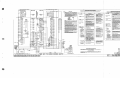
OPERATING TESTS FOR
Comect nil falo Tnt Set ud po.,;1Uoa nrttcbe• bl acccnkan WW. panp-aJ*a 1, l, :I ud fi Villlllr "Gflllnl".
'tboea~wWl~INUufollows. Afklrncltldt.ffUdl.udlculdbef:tt:U'JMllto---1~
!l!!!!!!!k
t ...Anl, ,p!,:11 camacton "A" ud "B.. to Offlce Lble Codta/1: UAll ud plq:
Jr§JJ
r------t,.
rlTCHES
'lbes poaed Wlt!I Gpff&lltc tests .. fo&W. After ,nd,, test. ...udMl lllloulbe , . . . _ lo awmal.
TESTING PROCEDURE
t....-..--t. ----fl• --<Fa II
l .
I
OPIIRA'IDIG fltlT8 :rGll ontCS umr:..coamo mum
c-act 1lz1t btoTuts.t _. posWQI nttdlu lm .ua:i,rdua 11'1.!J& ~ l. z. s u,d .. mder ••on..nr
I
FB 1ot..,ust, - - - t n - c
STATION
SELECTION
I
l
r:c. ••
_.....-.••,,,.,~.
c
,uoukJ
.+----i.o
I
, . _ _ _ _ _ _ , ,. . . .
I
:.aw,
· ..
I
FUNCTION
FUNCTION
I
1 CONTROL swtTCHES
1No1cAT10N sw1TcHEsl
ST£P fl
LINE
STEP fl
I
TEST
SWITCH
:,..-...
.-------------1--1
I
.a.rJ
l
• !l
It
I
h'
,•...•11.r,f'
I
I
1u
[TI§::
tr===1..
i--------@-
I
n.1
II
~"
i
.;
I
~"
1
.ST£P S c
•----:i
I
c
J
CIRCUIT TEST SWITCH I
l IrQl :
!4----"".a.
aI
rl"
io "
TEST LAMP
ST£P 14
1
I
aoo"'
,
~~~
"u"' ''
~
STEPU
•i--------@-<
"t::::::::""l'!
....
r---:'
·1;..
r,r,
"!
I ~.
4
STEP 12
I
·i 1
u
'
I
, • 5
n~
' ·
I
~ • ---I•
~
I
I
II
~===:
11
~-
ST_g" ,
't-----@--c
nl----,
,,I
,*1
I
:
: , t~ j·
uJ
":-----+:. t l
i - - - - . ,
• • • •
.....T-N
,ai----@-e
T
I
FUNCTION
I
CONTROL SWITCH I
JI
·
I
•
+--+,
"I+- ,J,
u
i---
•:
111.
FIELD BATTERY SWITCH
I •
' •: ~ I
I
f
I
FUKCTION
POSITION LAMPS I
I
f
::t::==:i J j
SR
I
f,
l
I
I
~11.&$1
:1
tP
, r
l ~1
: 11 l[ !
1
J
~
VOL~~)··
TEAMINAI..S
FIELD STORAGE I UNfT TERMDIALS
J
1
I
. ~ ,
PYRAMID
RELAYS
"i-------t
;;t:::=::;i I
~!
~
-
•I
OFFICE
,,1
1
I
I
FUNCTION
I
I INDICATION LAMPS "
SWITCHES
.> •
~>i
T
I
I
FlELO LINE-COOING- STORAGE UNIT
-;;r-
1~~
! ·o~~.~r··
STATION
SELECTION
j
I
'!L •
+------<D-- .c;,
r--------------1------1
! r-------------r---r----r--,
I
z~
: ;
r::::::"
jl
::.§1.
ll
..1
FIELD
I
I
5
;•zou:.----"
oe>- ........
... tr
c-zo
,o,..,.uu Oe
i1012w
OFFICE
•;
~•
ji.J 1
I
oh·
TERMINALS
-------,
rOIIPI.IICCOtlNCcn:HlaHOCAII.C-OIUUJltll-tJLfJG-111
"JO TIST FIJ:U)
VIEW 8
(c1RCUITPRtv1011s
R4
lOR(VISlm,IIS)
'-l••
H01t '• OGTTto t..llftS CONftCClnlO
TlfAY Yl!UII WUolllllS ARI
I
ROTARY CONTACTS or SWIY(.11(11, INOICATI
OPCJIIAT(O IY A COUUON SKA,T.
RJ:tlOoo"'
TEST SET TO CHECK CODING UJ~_ITS
PYRAY1D tnllT
Fteld PyruaSd Vall clrl:lllla ue cblcbcl bp appl,tac batttl'J' to atttalll t.tfllllia&ll to cptntl ttllp, &114 bJ
~ olhu drculla With a.ur, Tut Limp, •tc. TblN cll'culla UI · - Ol'I dn.Wllll D:15-tT-811. S, or
otbtrlpCCta!drawtllp.
POR l'ANCI. .....G Ht,-,.
---··--CUU•IM.111
nlllTlSYC<ll!JfUC-Ltl'CHC.
02547
SH.5
TtST
..
$1:T
5122, p. 15/16
WRSCCJ
~
SUGGESTED
UNIT
PIECE N O , - - - - - SERIAL NO. _ _ _ __
...
..
..
STEP NO .
Max. & Min.Length
of Long and Short
Code Steps,
measured in
Cycles, at 70° F.
with Local Batt.
16-18 Volts
(Freq. = 60 Cycles)
(See Notes Below)
Location of Unit
1
Short
.(Ind.Code)
8.5
12.5
Long
(Control Code)
21
28
2
3
4
Short
Short
Short Short
6
7
Short Short
8
9
Short
Short
FOR
11
10
Short Short
RECORDING
12
13
14
Short Short Short
TIMING
15
Short
DATA
16
Between
Consecutive Codes
'O
QI
c:
()
<ti
' -·:_.~:5·
4.5
6.5___ 6.5
Long Long
18
24
5
FORM
20
26
4.5
6.5
Long
18
24
4.5
6.5
Long
20
26
4.5
6.5
Long
18
24
4.5
6.5
Long
20
26
4.5
6.5
Long
18
24
4.5
6.5
Long
19
24
4.5
6.5
Long
17
22
4.5
6.5
Long
19
24
4.5
6.5
Long
17
22
4.5
6.5
Long
19
24
4.5
6.5
Long
17
22
4.5
6.5
Long
l9
24
Control Codes
57-61
Indication Codes
Without
SS
59-63
With
SS
75-85
i::i.
0
..... ,.....
0. <ti~
.-41
(I)
QI
()
<ti () 0
I-<
c:
:::>
t~
QI
~
A
QI
~
A
Q.>
c:
rJl
(I)
<ti .....
..:I~
QI
'a
-= 0.2!
QI
~
Q
REMARKS
>,
ix:i
(I)
~·:::..:I
=== s...
::I
~
!01
QI
.8
rJl
....
E-<
{Such as unusual conditons)
c:
QI
~
I
E-<
cl1
~
Measured length of code steps
I
I
NOTES
1. All tapes for field tests may be taken at the office. (To obtain timing with SS relay, someone must be
present at the field location to initiate consecutive indication codes. However, since the SS relay
timing is not critical, it need not necessarily be checked every time that field tests are made).
2. Specification limits for allowable length of each code step are shown at the top of the column for the
code step to which they apply. These limits are specified in terms of cycles (60 cycles = 1 second)
and based on temperature of 70° F. When making tests, actual temperature of unit being tested should
be recorded. Timing data should be corrected for temperature in accordance with table in Instruction
Pamphlet U-5122 , when actual temperature of unit differs from 70° F. by morP. than 35° F.
When frequency used in obtaining timing data is other than 60 cycles per second, specified timing values
should be evaluated in terms of the new frequency as follows:
Specified timing values X new fr:iuency
i
Values shown are those obtained when unit is in service on a D.C. cocje
line or when timing is measured at field. For timing of field units
(measured at office) for carrier controlled sections see proper table
under Field Maintenance Tests.
3. If the timing of a particular code step is within 1/2 cycle of the limits, take a second tape and record
the longest count.
--
5122,p.17/18
."'
\'.
'.
t
' ..... [
"
.
WABCC
An American-Standard Company
UNION SWITCH & SIGNAL DIVISION
WESTINGHOUSE AIR BRAKE COMPANY
Swissvale, PA 15218
...