1
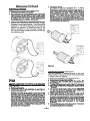
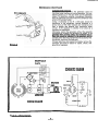
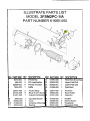
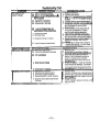
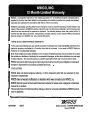
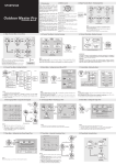
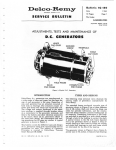
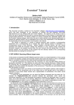
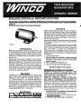
INSTALLATION, OPERATION, and MAINTENANCE INSTRUCTIONS
READ INSTRUCTIONS CAREFULLY BEFORE ATTEMPTING TO OPERATE OR SERVICE THE DAYTON GENERATOR. FAILURE TO COMPLY WITH INSTRUCTIONS COULD RESULT IN PERSONAL INJURY AND/OR PROPERTY
DAMAGE!
RETAIN INSTRUCTIONS FOR FUTURE REFERENCE.
Unpacking
Testing Policy
Before any generator is shipped from the factory it is
fully checked for performance. The generator is loaded
to ~ t sfull capacity, and the voltage, current, and frequenc are carefully checked. A test card with this data
is file by unit serial number for permanent record of
performance.
Rated output of generators is based on factory tests of
typical units, and is subject to and limited by the ambient
operating temperature. The generator will not provide
full power output unless driven by a prime mover of
adequate horsepower. The prime mover (engine or
other input power source) horsepower is also affected
by temperature as well as a number of other factors
such as fuel, altitude and all other conditions specified
by the prime mover manufacturer.
d
Description
The WlNCO generator is a 3600 RPM two bearing, belt
driven, brush type, revolving armature design. The
generator is self excited and inherently regulated to
+/- (plus or minus) 7% - no load to full rated load. It
can be operated under any load within its rating without
being damaged. The frequency regulator is determined
by the sensitivity of the customer supplied prime movers' governor. It is desirable to maintain this speed to
within 3 cycles variation (61.5 Hz - 58.5 Hz) no load to
full rated load (3690 RPM - 3510 RPM).
Specifications
1
2,000
PH
VOLTS AMPS HZ
WkrrS
1
120
1
16.7
(
60
1
RPM
INSULATION
1 136001Class B
I
When unpacking the generator, be sure to inspect it
carefully for freight loss or damage. If loss or damage is
noted at the time of delivery, require that the person
making the delivery make note of the loss or damage on
the freight bill, or affix his signature under the consigner's memo of the loss or damage. Contact the carrier for claim procedures.
When loss or damage is noted after delivery, segregate
the damaged material, and contact the carrier for claim
procedures.
"Concealed damage" is understoodto mean damage to
the contents of a packagewhich is not in evidence at the
time of delivery by the carrier, but which is discovered
later. The carrier or carriers are responsible for
merchandise lost or damaged in transit. The title of
goods rests with the consignee when generators are
shipped FOB factory. And only the consignee can legally file claims.
1. Carefully open carton.
2. After inspecting the generator for external physical
damage, check for the owner's manual (operating
instructions, wiring diagram, parts list, and warranty)
inside the carton.
3. Remove generator hold down bolts.
4. Unit can now be lifted from shipping base.
General Safety Information
DEFINITION OF CAUTIONS AND WARNINGS
CAUTION: Possible damage to equipment. Notes
indicate any condition or practice, which if not
strictly observed or remedied, could result in damage or destruction of the equipment.
WARNING: PERSONAL DANGER. NOTES INDICATE ANY CONDITION OR PRACTICE, WHICH IF
NOT STRICTLY OBSERVED, COULD RESULT IN
PERSONAL INJURY OR POSSIBLE LOSS OF LIFE.
Despite the safe design of this generator, operating it
imprudently, neglecting its maintenance, or being careless with it can cause serious injury or death. This
generator is powerful enough to deliver a fatal electric
shock. Allow only a responsible and capable person to
operate this generator.
1. For permanent wiring or wiring into existing electrical
service or system, the installation must comply with
all national, state and local codes.
2. Do not allow anyone to operate the generator without proper instruction.
3. Avoid touching live terminals or receptacles.
I
General Safety Information (Cont'd)
4. Be extremely careful if operating this generator in
rain or snow.
5. This generator must be properly grounded.
6. Hot prime mover (engine) parts, movingdrive parts,
and generator output, all can seriously injure the
generator operator. The operator must use caution
and remain alert when using this generator.
7. Keep all safety guards and drive shields in position
and tightly secured while equipment is operating.
8. When operating this generator, do not wear neckties, loose articles of clothing or anything else that
can be caught in moving parts.
9 Provide adequate ventilation for prime mover exhaust and fuel vapors that may leak through fittings
or damaged pipes. Be sure generator itself is well
ventilated for maximum performance and life.
10. The generator manufacturer recommendsthat only
qualified electrical technicians be allowed to
service (install, maintain, repair, or replace parts)
this generator, and that only factory approved repair parts be used in it.
11. Do not work on this generator (or other potentially
hazardous equipment) when fatigued.
12. Use extreme caution when working on electrical
components. High generator output voltage can
cause serious injury or death.
13. Keep the generator and the area around it clean.
Remove all material that can create slippery conditions, such as grease, water, ice and snow. Also
remove oily rags and other flammable materialfrom
the area.
14. Keep a fire extinguisher near the generator. Extinuishers rated ABC by the NFPA are appropriate
or this use. Consult the local fire department if you
have questions regarding fire extinguisher ratings.
Keep the extinguisher properly maintained and be
familiar with its proper use.
9
Installation
CAUTION: Before proceeding with the installation, be
sure that you have completely read and understood
the assembly and installation instructions.
An engine with adequate horsepower and a close regulating (fixed speed) governor is required for satisfactory
operation of any alternating current generator.
About 1.4 horsepower is required to produce each 1000
watts of generator output power assuming 10O0/0 efficiency of both the engine and the generator. However,
due to engine and generator efficiencies of 80 to 9O0/0,
the loss of power due to engine driving accessories such
as cooling fans, battery charging alternators, etc., friction
losses and slippage in the drive pullies and belts, the general conservative rule of thumb allowing approximately
two (2) horsepower for every 1000 watts of generator
output is much more realistic.
For example, this 2.000 watt generator output will require
a 4 or 5 H.P. engine for full output, good speed/voltage
regulation, and satisfactory load performance.
When determining the prime mover/generator pulley ratio
to drive the generator at the correct operating speed.
bear in mind that the power rating of most prime movers
(usually an engine) varies with the speed - that is. it produces more power at higher speeds, less when slowed.
The prime mover must be run fast enough -to reach the
desired horsepower for good gemrator set operation.
The drive belt system must be of adequate size and must
be tight enough to power the generator without slippage.
Be careful not to overtighten to the extent that it puts excessive strain on the bearings - doing so can cause
bearing failure and other possible damage to the generator.
Alignment of the generator to the prime mover is important. Misalignment of the pullies will cause excessive belt
and pulley wear and unnecessary stress on the prime
mover.
The following table shows the effect of various operating
speeds and electrical loads on a typical generator when
matched and mounted to an adequate prime mover.
The following table shows the effect of various operating
speeds and electrical loads on a typical generator when
matched and mounted to an adequate prime mover.
Although individual units and models may vary slightly,
the normal voltage and frequency of typical 60 cycle
engine-driven generators described in this manual are approximately as follows when powered by a typical prime
mover (engine) run first with no load applied, then at half
the generator capacity and finally when loaded to its full
capacity as rated on the nameplate.
GENERATOR
LOAD
None
Half
Full
SPEED
FREQUENCY
3690 RPM 61-1/2 Hz
3600 RPM
60 Hz
13510RPM I 58-1/2Hz
VOLTAGE
I
129 Volts
120 Volts
115Volts
I
NOTE: Required generator speed must be maintained
at 3600 + / - 90 RPM under all load conditions.
All engines have a tendency to slow down when a load is
applied. The governor on the engine is designed to hold
the engine speed nearly constant. When the electrical
load connected to the generator is increased, the engine is more heavily loaded and as a resu't the speed
drops slightly. This slight decrease in spesd together
with the natural "voltage drop" within the generator itself
due to load current and heating of the windings, results
in a slightly lower voltage than when the generator is
running idle.
The normal slight variations in speed also directly affect
the frequency of the output current. This frequency variation has no appreciable effect in the operation of most
loads (such as motors, lights and most small appliances). However, timing devices and clocks will not
keep perfect time unless the engine can keep the
enerator running at exactly 3600 RPM at all times.
ince this is not usually possible, mrnor time errors in
clocks occur.
The speed of the engine is usually adjusted so that the
generator produces proper voltage. If the adjustment is
made "cold," set the voltage a little higher than normal
since it will drop a few volts as the generator warms up.
NOTE: When operating continuously at full load the
enerator shell becomes very warm. It will be uncomortable to the touch - this is normal for any high
performance inherently regulated generator.
Output voltage should be checked periodically to ensure proper operation of the generating plant and
appliances.
CAUTION: Low voltage may damage any motors or
appliances connected to it. Running the generator
at excessively high speeds results in too high voltage which will also damage electrical devices connected to it. Excessively high speed may also cause
damage to the generator armature windings.
8
9
residual voltage level (nearly zero - typically 3 to 7
volts). The exciter voltage is also taken from. the
generator ouptut voltage. Since there is no exciter voltage, the generator magnetic field 'collapses'. Now
thefe is virtually no load on the generator or engine, so
no harm is done to either.
Under these conditionsi the motor may revolve a few
times when it is first turned on, and then stop when the
generator field collapses under massive overloads. The
generator is self or inherently protected and since the
generator is producing nearly zero voltage, the motor or
other load is not damaged in any way.
CAUTION: On the other hand, an electric motor that
requires slightly more output than the generator
can produce will run, but will not reach a high
enough speed for the centrifugal switch to disconnect the starting winding. The generator output voltage, instead of being 115, may drop t o 70 or 80
volts. Running the generator under these conditions may result in burning out the motor start winding. Exercise care the first time each new load is
energized to be sure that the load is compatible and
within the capacity of the generator.
Because the heavy surge of, current required for
starting motors is required for only an instant, the
generator will not be damaged if it can bring the
motor up to speed in a few seconds of time. If difficulty i s experienced in starting motors, turn off all
other electrical loads and, if possible, reduce the
load on the electric motor.
Assembly (Continued)
Plans for installation should be prepared with proper
attention to mechanical and electrical engineering detail
to assure a satisfactory system installation. The information in this manual is offered as a guide to finalizing
your installation plans. The installation sequence is
summarized below.
PLAN THE INSTALLATION
Generally these two-bearing generators are used on
portable equipment. For best service consider the
following:
1. All electrical equipment should be protected from
excessive moisture. Failure to do so will result in
deterioration of the insulation and short circuits and
grounds.
2. The generator should be installed in a sheltered
area. If the unit must be left in the open it should
always be protected with a weather cover such as a
tarp or large piece of canvas after each use to keep
out water and dust.
CAUTION: Always a l l ~ wthe generator and prime
mover to cool before covering with a flammable
weather covering.
MOUNTING
CAUTION: The generator must be mounted with the
engine to a common rigid base to prevent stress on
the engine and generator shafts and bearings due
t o vibration displacement. For permanent installations, the engine-generator is usually mounted on a
sub-frame which can be shock mounted with special neoprene pads on the main frame.
Maintenance
GENERAL
The main components of the generator are: field frame,
field coils, armature, brushes. brush holder assemblv..
brackets, armature, and generator cooling fan.
Operation
.
USE OF ELECTRIC MOTORS
Electric motors reauire much more current [am~ereslto
help start them ihan to run them. ~ e r i a i nmotors,
'
articularly inexpensive split-phase motors are very
ard to start. Typically, they require 7 to 10 times as
much current to start them as to run them. Capacitor
motors are easier to start but still require 3 to 5 times
their running current to start. Repulsion induction
motors are the easiest to start and usually require only 2
to 4 times their running current to start. Refer to the
nameplate of the generator for the running current
(ampere rating) and starting code of your motors.
NOTE: The starting code is an alpha character - 'A'
code motors are the easiest to start; 'R', 'S', or 'T' code
motors are very hard starting.
Most fractional horsepower motors take about the same
amount of current to run them regardless of their type of
construction (repulsion-induction (RI), capacitor (CAP),
or split-phase (SP) type).
A self-excited generator responds differently to severe
overloading than a transformer connected to a power
line. To illustrate, suppose that a 115 volt 5 H.P.
"capac~torstart-induct~onrun" motor is connected to a
small transformer with a maximum rating of 2,000 watts
and then to a generator of 2,000 watts capacity.
The transformer would not be able to supply enough
power to bring the motor up to operating speed, but
would be very severely overloaded and probably would
burn out in a short time. The motor might also be
damaged.
When this motor is connected to a self-excited 2,000
watt generator, the generator output voltage drops to its
BRUSHES
Under ordinary circumstances brushes will operate for
thousands of hours without requiring replacement. They
should be inspected after the'first 1000 hours of operation, and after every 500 hours of operation thereafter.
Remove brushes one at a time and check for length. Be
sure that each moves freely in the brush holder.
Brushes should be replaced whenworn down to 3/8".
Always replace brushes in complete sets, never singly.
When replacing brushes be careful to reconnect the
lead wire properly. Poor contact or "skipping" between
brush and slip ring can be caused by oil and grit, flint, or
other hard contaminant substances on the brushes, or
by the brush not being properly shaped to fit the slip
rings.
. .
Remedy these defects by cleaning the iings and
brushes and then fitting the brqshes to the slip-ring
curvature. Place #00 sandpaper under the brushes with
the abrasive side to the brushes, and workit back and
forth until the brushes are the same shape as the sliprings.
SLIP RINGS
The continuous copper rings located at the end of the
.armature are the power collector rings or 'slip rings.' For
proper generator output, the surface of these slip rings
must have a highly polished finish. Under sustained
use, it is advisable to check and occasionally polish the
ring surfaces with a crocus cloth to maintain the finish
under normal conditions. This should not be required
more than once each thousand hours of operation.
C
p
-3-
Maintenance (Continued)
ELECTRICAL TESTING
Testing generator field for opens and grounds.
1. Disconnect field lead from rectifier.
2. Set multimeter to read resistance, and connect the
meter leads to the field leads. If field is open, meter
will read infinite resistance (very high ohms). Repair
or replace field if it is open. Typical resistance for
these fields vary from 12.8 to 14.1 ohms.
3. Leaving one meter lead connected to the field, connect the other meter lead to the field shell. If meter
indicates continuity (any reading- should be infinite
resistance). The field is grounded and should be
repaired or replaced. To determine which of the
fields is grounded, cut the connector between the
two coils and retest to determine which coil has the
low resistance path.
3. Testing for opens
Set meter to read low resistance (R x 1 ohms).
Holding one meter lead on surface of slip ring No. 1,
touch other meter lead to surface of slip ring No. 2
while observing the meter. Meter should indicate
continuity (low resistance - less than one ohm is
typical). If the meter indicates open circuit (infinite
resistance) part of armature winding is open. This
may be caused by a repairable defect in the connection at the slip ring, however generally an open armature will have to be replaced.
Figure
-- 3
Figure
- 2
TESTING ARMATURE FOR OPENS AND C%OUNDS
(See Figure 3)
1. Remove all brushes.
2. Ground fault test set multimeter to read high tesistance (meg-ohms).
Holding one meter lead against a clean spot on the
armature shaft, touch the other lead to each of the
slip rings (one at a time) while observing the meter. If
meter Indicates continuity (any reading lower than
one meg-ohm), the armature IS grounded. Dirt between the slip rings and on the insulator surface can
cause grounding. If grounding was indicated, carefully clean all dirt off the slip rings and their insulators
and then recheck it. Replace the armature if ~tis
grounded and unrepairable.
-
-4-
TESTING RECTIFIERS (See Figure 4)
The field excitation is supplied through a half wave
bridge rectifier. This type of rectifier has three terminals
-two AC, and a DC positive.
A rectifier may be tested in the following manner:
1. Disconnect all leads from rectifier.
2. Connect the red ohmmeter lead to the positive DC
(+) terminal.
3. Connect the black lead to each of the AC terminals in
turn. Either a high or low resistance reading will be
obtained.
4. Reverse the meter leads, (black lead to the
pas
(+) and red to the AC terminals, each in turn. An
opposite reading should be observed.
5. Check each terminal to the Case. An Open circuit
(very high resistance) reading should be observed.
A battery powered test light is used. Follow the same
procedures described above. A good diode element
will allow current to pass to the light in the test lamp
when the leads are connected in the forward
direction.
6. If the rectifier falls any of the above tests, it should be
considered defective and replaced.
Maintenance (Continued)
CONDENSER TESTING
Condensers are built into the generator circuit t o '
minimize radio interference during operation. If a condenser shorts out, it will also short out the generator
output. To determine whether a condenser is shorted,
stop the generator and disconnect the condenser lead
wire from the brush holder.
Using a multimeter on the R x 100 scale, check the
resistance of the condenser. Normal response is a
sharp swing of the meter towards low resistance and
then a steady rise towards high resistance (open
circuit). If the capacitor is shorted it will show as a
constant low resistance.
Otherwise, restart the generator without the capacitor
connected to recheck the generator for output. If the .
enerator then provides power, the condenser was at
ault and should be replaced. (If the generator did not
provide power after the problem was not caused by that
condenser, reconnect the lead wire).
If these tests have not located the trouble, remove the
armature and have it tested for opens, shorts, and
grounds on a growler.
RED (+I
TEST LEAD
?
Figure 4
RECEPTACLE
PLATE
SCHEMATIC DIAGRAM
BEARING
END
---ARMATURE
WIRING DIAGRAM
Egure 5 - Wiring Diagram
-5-
ILLUSTRATE PARTS LIST
MODEL 2FSM2PC-1IA
PART NUMBER 61685-000
REF PART NBR QTY DESCRIPTION
REF PART NBR QTY DESCRIPTION
1
2
3
4
6372-000
484-000
20556-002
7924-000
4
4
4
1
#lo-32 Nut
# I 0 Lockwasher
# I 0-32 Thru Bolt
Baffle
12
13
14
15
61687-000
60925-000
60925-001
61689-000
1
1
1
1
Field Shell & Coil Assy
Upper Field Coil
Lower Field Coil
Field Shell
5
6
7
20557-000
40746-000
61427-000
2
6
1
Anchorstrap
16
#8-32 X 5116 Screw 17
Output End Bracket 18
23607-000
59690-000
41221-000
3
3
2
AC Brush
Brush Holder
Capacitor
8
9
10
11
8929-000
60928-000
61426-000
55223-000
1
1
1
2
Input End Bracket
19
Cover
20
Armature wlBearings 21
Bearing
22
91452-000
59688-000
60960-000
60931-000
I
3
2
1
Rectifier
Barrier Spacer
Receptacle
Receptacle Plate
L(
SYMPTOM
No output or low
output voltage
Troubleshooting Chart
POSSIBLE CAUSE@)
1. Open or shorted armature
.
2. Open or shorted field coil(s)
3. Generator operating below correct
RPM speed
4. Generator overloaded
5. Short circuit in the load
6. Loose (or broken) wires or
connections in the control box
7. Defective rectifier
8. Dirty slip rings
9. Brushes binding in holders
10. Loss of residual magnetism
Output voltage too high
Generator overheating
Engine speed too high
1. Generator overloaded
2. Armature rubbing pole shoes
3. Poor ventilation
4. Short circuit in fields
Sparking at the brushes
5. Short turns in armature
1. Generator overloaded
2. Brushes not seated properly
3. Slip rings rough or eccentric
4. Brushes sticking in brush holder
5. Brushes worn down shorter than
318 inch
CORRECTIVE ACTION
1. Replace armature.
2. Replace field coil(s).
3. Generator must be operated at 3600
RPM, +/- 90 RPM for proper output
voltage.
4. Reduce load to generator nameplate.
5. Disconnect the load. Check voltage at
receptacle. Check motors, appliances
and load leads for short circuits.
Repair short.
6. Remove panel cover and check all
wiring and connections. Tighten
and/or repair where necessary.
7. Test rectifier. Replace if defective.
8. Clean and polish. Use 00 sandpaper
and crocus cloth, never emery paper.
9. Check brushes for swelling. Replace
defective brushes. Clean brush
holders.
10. Check output voltage with sensitive
meter. If very low (eg. 1/2 volt) flash
fields with 12 VDC'battery.
See engine manual.
1. Reduce load.
2. Check bearing condition. Check
field shell bearing bracket alignment.
3. Clear inlet and outlet air vents of
debris. If unit is housed, ensure at
least 2 ft. clearance on all sides
and that inlet and outlet vents are of
adequate size.
4. Repair or replace -open or shorted
fields should be replaced. Grounded
fields may be repaired by insulating
at the point where the ground occurs.
5. Replace arm.
1. Reduce load.
2. Contour brushes (see maintenance).
3. Redress slip rings (see maintenance).
4. Remove brushes and inspect and correct problem.
5. Replace brush.
NOTE: Always replace brushes a full
set at a time.
WINCO, Incorporated warrants to the original purchaser for 12 months that goods manufactured or
supplied by it will be free from defects in workmanship and material, provided such goods are installed,
operated and maintained in accordance with Winco written instructions.
WINCO's sole liability, and Purchaser's sole remedy for a failure under this warranty, shall be limitedto the
repair of the product. At WINCO's option, material found to be defective in material or workmanship under
normal use and service will be repaired or replaced. For warranty service, return the product within 12
months from the date of purchase, transportation charges prepaid, to your nearest WlNCO Authorized
Service Center or to WINCO, Inc. at Le Center Minnesota
I
THERE IS NO OTHER EXPRESS WARRANTY.
To the extent permitted by law, any and all warranties, including those of merchantability and fitness for a
particular purpose, are limited to 12 months from date of purchase. In no event is WlNCO liable for
incidental or consequential damages.
Note: Some states do not allow limitation on the duration of implied warranty and some states do no allow
the exclusion or limitation of incidental or consequential damages, so the above limitations may not apply
in every instance. This warranty gives you specific legal rights which may vary from state to state.
WlNCO reserves the right to change or improve its productswithout incurringany obligations to make such
changes or improvement on products purchased previously. .
WlNCO does not warrant engines, batteries, or other component parts that are warranted by thier
respective manufacturers.
WlNCO does not warrant modifications or alterations which were not made by the WINCO, Inc.
WlNCO does not warrant products which have been subjected to misuse and/or negligence or have been
involved in an accident.
This warranty does not includetravel time, mileage, or labor for removalor reinstallationof WlNCO product
from its application.
ZSSoulh Cordova St. I LE CENTER, MINNESOTA -7
Phone: (612) 3516821