1
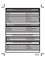
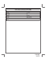
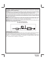
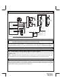
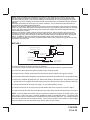
IMPORTANT!
DO NOT PLUG THE EIGHT PIN MAIN POWER HARNESS OR THE MULTI PIN INPUT / OUTPUT
HARNESS INTO THE CONTROL MODULE UNTIL ALL CONNECTIONS TO THE VEHICLE HAVE BEEN
MADE. AFTER SELECTING YOUR TARGET WIRES AS DEFINED BELOW, DISCONNECT THE NEGATIVE BATTERY CABLE FROM THE VEHICLE BATTERY PRIOR TO MAKING ANY CONNECTIONS.
NOTE: Do not remove the fuse holders from this wire harness. Fuses must be used and located as close as possible to the power source for adequate protection of the vehicle.
WIRING THE 8 PIN MAIN POWER HARNESS:
PART # 1124299
NOTE: Do not remove the fuse holders from this wire harness. Fuses must be
used and located as close as possible to the power source for adequate protection of the vehicle.
1 BLUE Wire: Ignition 1 Output
Connect this wire to the ignition 1 wire from the ignition switch. This wire will show +12 volts when the
ignition key is turned to the "ON" or "RUN" and the "START" or CRANK" positions, and will have 0 volts
when the key is turned to the "OFF" and "ACCESSORY" positions.
For Diesel Applications, this wire must be connected to the ignition circuit that powers the glow plugs if
the vehicle requires glow plug pre-heating. (See selectable feature Bank 3 #12)
2 RED/WHITE WIRE: + 12 volt Battery 1 Source Fused 30A
Locate the vehicle battery wire(s) at the ignition switch. Verification: These wires will register voltage in all positions
of the ignition switch. Connect the Red w/White wire to the vehicle's battery wire. This wire provides power for the
control circuit as well as the ignition 1 and ignition 2 relays.
3 GREEN Wire: Ignition 2 Output
Connect this wire to the ignition 2 wire from the ignition switch. This wire will show + 12 volts when the
ignition key is turned to the "ON" or "RUN" position and is some cases the "START" or CRANK" position.
This wire will show 0 volts when the key is turned to the "OFF" and "ACCESSORY" positions.
NOTE: See programming information (Bank 3 Selection #7) concerning this wire to allow output during
the "START" mode.
4 PINK Wire: Additional Ignition Output
This wire can be used as an additional + 12 Volt ignition output supplied by the Red/Black wire. This
output can be selected to be on or off during the start cycle. (See feature bank 3 selection # 8) Connect
this wire to the third ignition circuit in the vehicle and set the selectable feature # 8 of Bank 3 according
to the way in which the vehicle's ignition switch operates.
5 PURPLE Wire: Accessory Output
Connect this wire to the Accessory wire from the ignition switch. This wire will show + 12 volts when the
ignition switch is turned to the "ACCESSORY" or "ON" and "RUN" positions, and will show 0 volts when
the key is turned to the "OFF" and "START" or "CRANK" positions.
6 RED WIRE: + 12 Volt Battery 2 Source Fused 30A
Locate the vehicle battery wire(s) at the ignition switch. Verification: These wires will register voltage in all positions
of the ignition switch. Connect the Red wire to the vehicle's battery wire. This wire provides power for the start
relay and the accessory relay.
7 YELLOW Wire: Starter Output
Careful consideration for the connection of this wire must be made to prevent the vehicle from
starting while in gear. Understanding the difference between a mechanical and an electrical
7
128-9308
7 of 32