1
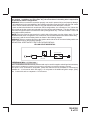
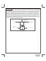
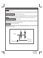
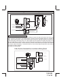
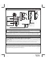
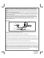
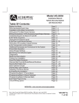
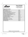
WIRING CONNECTIONS: 22 Pin Accessory Input/Output Harness PART # 1124300
1 Green w/ White trace Wire: Entry Illumination Ground Output
This wire provides a 30 second ground output, (300 mA Max.), whenever the remote is used to disarm
the alarm or to unlock the doors. It also provides a continuous pulsed output whenever the alarm is
triggered. This wire should be connected to an external relay and wired to the vehicles interior entry
lighting circuit whenever the optional Entry Interior Illumination feature is desired.
2 LT. Blue Wire: Ground Output While Running (-) 300mA
This wire provides a 300mA ground output that becomes active 1.5 seconds before the Remote Start
Unit initializes and remains grounded while running plus an additional 2 seconds after the Remote Start
Unit turns off. In all of the applications described below, a relay will be required.
The Light Blue wire can be used to accommodate the following situations:
A. Sensor By Pass:
If there is a Non Plug in Sensor used with the alarm system and it is not shunted during the Remote
Start activation period, then vibration or noise from the running vehicle can cause the alarm to trigger.
In this case, connect the Light Blue Wire to terminal #86 of a external relay. Connect terminal # 85 of
the relay to a fused + 12 volt battery source. Cut the sensor's trigger wire and connect one end of the
cut wire to terminal #30 and the other end of the cut wire to terminal #87a. Just before the Remote
Start unit is activated, the relay contacts will open, preventing the sensor's operation until the Remote
Start unit shuts off.
B. Additional Ignition Output:
Some vehicle's may require more than three ignition outputs to start and keep the vehicle's engine
running. If this is the case, connect the Light Blue wire to terminal #86 of an external relay. Connect
terminal # 85 to a fused + 12 volt source. Dependent on the vehicle's requirement, connect terminal
#30, to a fused + 12 volt source, or to ground, and connect terminal 87 to the vehicle to supply the
additional ignition source.
C. GM VATS Key Override:
If the vehicle has the General Motors VATS system installed, you will need to bypass the system while
the vehicle is operating under the control of the Remote Start Unit. To Do This:
1. Measure the resistance of the resistor pellet on the ignition key then select a resistor within 5% of
the key's value
2. Locate the pair of VATS wires in the vehicle, usually a pair of thin gauge wires running from the
ignition switch to the VATS control module.
NOTE: These wires are typically White w/ Black trace and Violet w/ Yellow trace, however in later model
Cadillacs, they are run through an orange sleeve, and are either both Black, both Yellow, or both
White wires. Consult the factory service manual for additional information.
3. Connect the Light Blue Wire from the Remote Start Unit to terminal #86 of an external relay. Connect
terminal #85 of the relay to a fused + 12 volt battery source.
4. Cut (#1) wire (as shown), and connect the ignition switch side of the cut wire to terminal #87a of the
relay. Connect the other side of the (#1) wire to terminal #30.
5. Connect the previously selected resistor from terminal #87 to the second (#2) wire (as shown).
NOTE: The above information and following diagram is for the GM VATS system only.
9
128-9308
9 of 32