1
!
!!!!!!!!!!!!!!!!!!!!!!!!!!!!!!!!!!!!!!!!"#$%&'()*%!+#,&-('.!!!!!!
!!!!!!!!!!!!!!!!!!!!!!!!!!!!!!!!!!!!!!!!!!!!!!!!!!!!/!0$)%1!2%,#$!
!!!!!!!!!!!!!!!!!!!!!!!!!!!!!!!!!!!!!!!340!2$'*$5!!!!!!!!!!!
!!!!!!!!!!!!!!!!!!!!!!!!!!!!!!!!!!!!!!!!!!!!!!!!!!!
!
!
!
!
!
!
!
!
!
!
!
!
!
!
!
!
!
!
CTB serial bench scale service manual
UGCTB-E1.0
Table of Contents
SECTION 1 INTRODUCTION…………………………………………………………1
SECTION 2 SPECIFICATIONS……………………………………………………..…2
SECTION 3 INSTALLATION……………………………………………………………3
SECTION 4 KEY DESCRIPTIONS……………………………………………………4
SECTION 5 DISPLAYS…………………………………………………………………5
SECTION 6 OPERATION…………………….……………………………………….…6
6.1 Zeroing the display………………………………………………………………….6
6.2 Taring……………………………………………………………………………..……6
6.3 Weighing a sample…….………………………………………………….………….6
6.4 Parts counting…………………………………………………………………………6
6.5 Check-weighing…………………………………………………………………….7
6.6 Accumulated total……………………………………………………………………8
6.7 Net/gross change …………………………………………………………………….8
SECTION 7 PARAMETERS…………………………………………………………9
SECTION 8 BATTERY OPERATION………………………………………………..…11
SECTION 9 RS-232 OUTPUT………………………………………………………….12
SECTION 10 CALIBRATION……………………………………………………..…….13
SECTION 11 TECHNICAL PARAMETES…………………………………………….14
SECTION 12 TROUBLE SELFCHECKING…………………………..…….……... 15
SECTION 13 TROUBLESHOOTING………………………………….………………16
13.1 No power………………………………………………….…………….…………. 16
13.2 No display…………………………………………………………..………..……. 17
13.3 Can’t charge the battery…………………………………………..………………18
13.4 Can’t weighing……………………………………………………………………. .19
13.5 Reading jump……………………………………………………………..………..20
13.6 Keyboard can’t work……………………………………………………………….20
II
CTB serial bench scale service manual
SECTION14 CHANGE PARTS PROCESS…………………………………………...21
14.1 Replace main board……………………………………………………….……....21
14.2 Replace load cell……………………………………………………..……………21
14.3 Replace MPU…………………………………………….………………………...22
14.4 Replace battery………………………………………………….…………………22
SECTION15APPENDIX…………………….………………………………………..…23
15.1 Schematic (main)…………………………………………………………….….…23
15.2 Schematic (display)………………………………………..………….……..……24
15.3 Parts drawing…………………………………………….…………..…….……...25
15.4 Parts list…………………………………………………….……………….……...26
15.5 Error codes…………………………………………………………………………27
15.6 Numeric and alphabetic characters displayed on LCD……………….……….27
III
CTB serial bench scale service manual
SECTION 1 INTRODUCTION
The CTB series of bench scale provides an accurate, fast and versatile series of
general purpose weighing scale with counting and check-weighing functions.
There are 3 series scales within the range, the platform size from 420mm x 520mm ,
the capacity range from 150lb to 600lb.
All the keypads are sealed, color coded membrane switches and the displays are
large easy to read liquid crystal type displays (LCD). The LCD’s are supplied with a
backlight.
All units include automatic zero tracking, audible alarm for pre-set weights, automatic
tare, and an accumulation facility that allows the individual weights to be stored and
recalled as an accumulated total.
1
CTB serial bench scale service manual
SECTION 2 SPECIFICATIONS
Model
CTB-150
CTB-300
CTB-600
Platform size
420mm x 520mm
420mm x 520mm
420mm x520mm
Capacity
150lb
300lb
600lb
Resolution
1:3000
Interface
RS-232 Output Optional (standby)
Stabilisation Time
1 Seconds typical
Operating
Temperature
5°C - 35°C / 41°F - 95°F
Power supply
External AC adapter, 9V 800mA
Calibration
Automatic External
Display
6 digits LCD digital display with 24mm high digits
Balance Housing
Indicator ABS Plastic
Load cell
voltage
Max 5V/150mA
Load cells
drive
Up to four 350 ohms cells
2
CTB serial bench scale service manual
SECTION 3 INSTALLATION
GENERAL INSTALLATION
The scales should be sited in a location that will not degrade the accuracy.
Avoid extremes of temperature. Do not place in direct sunlight or near air conditioning
vents.
Avoid unsuitable tables. The tables or floor must be rigid and not vibrate. Do not
place near vibrating machinery.
Avoid unstable power sources. Do not use near large users of electricity such as
welding equipment or large motors.
Avoid high humidity that might cause condensation. Avoid direct contact with water.
Do not spray or immerse the scales in water.
Avoid air movement such as from fans or opening doors. Do not place near open
windows.
Keep the scales clean.
Do not stack material on the scales when they are not in use.
INSTALLATION OF CTB SERIES
The pillar is attached to the base using a bracket that must first be attached to the
base frame using the 4 bolts supplied. The Pillar is secured to the bracket using 2
set screws. The cable from the base to the indicator module is run through the tube,
out through the plastic support at the top. Excess cable can be stored within the
tube.
The CTB Series comes with a stainless steel platform packed separately. Place the
platform in the base.
Level the scale by adjusting the four feet. The scale should be adjusted such that the
bubble in the spirit level is in the centre of the level and the scale is supported by all
four feet. If the scale rocks readjust the feet.
Attach the indicator module to the pillar by sliding it over the bracket with the flanges
engaged in the groves on the base.
Attach the AC power adapter to the connector on the back of the indicator.
3
CTB serial bench scale service manual
SECTION 4 KEY DESCRIPTIONS
Zero or
Set the zero point for all subsequent weighing. The display shows zero.
A secondary function
, of "Enter" key when setting parameters or other functions.
Tare or
Tares the scale. Stores the current weight in memory as a tare value, subtracts the
tare value from the weight and shows the results. This is the net weight. Entering a
value using the keypad will store that value as the tare value.
A secondary function +, of incrementing the active digit when setting a value for
parameters or other functions.
Smpl or
Enter counting mode from weighing mode. Shift unit weight, counts and total weight
when counting mode. Move the active digit right when setting values for other
functions.
The second function, when the scale self-check press the key, it will show ”CAL X”, it
is an arithmometer (COUNTER) for the times of calibration is successful.
N/G
Used to select the weight model of the scale. If the scale has tared, switch to the
mode of net weight or gross weight. Move the active digit left when setting values for
other functions.
The second function, when the scale self-check press the key, it will show “opt X”, it
is an arithmometer (COUNTER) for the times of parameter setting.
Func or F
Used to select the function of the scale. If the scale is weighing it will select parts
counting. Of it is not in weighing mode it will return the user to weighing.
Secondary function ( C ) , is to act as a clear key when setting values for parameters
or other functions.
Print or
To print the results to a PC or printer using the optional RS-232 interface. It also
adds the value to the accumulation memory if the accumulation function is not
automatic.
Secondary function (ESC) , is to return to normal operation when the scale is in a
parameter setting mode.
ON/ OFF or
Turn on or off the power.
4
CTB serial bench scale service manual
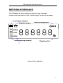
SECTION 5 DISPLAYS
The LCD display will show a value and a unit to the right of the digits.
In addition there are labels for TARE, GROSS weight, Zero and for Low battery
Low Battery Symbol
Stability Symbol
Parts Counting Units
/pcs
HI GROSS
OK TARE
lb
LO ZERO
Checkweighing Symbols
Weighing Units
Center of Zero Indication
5
CTB serial bench scale service manual
SECTION 6 OPERATION
6.1 Zeroing The Display
You can press the ZERO/ENTER key at any time to set the zero point from which all
other weighing and counting is measured, within set % in 0-Range parameter from
power up zero. This will usually only be necessary when the platform is empty.
When the zero point is within “CENTRE OF ZERO” range display will show the
indicator for “zero”.
The scale has an automatic rezeroing function to account for minor drifting or
accumulation of material on the platform. However you may need to press the
ZERO/ENTER key to rezero the scale if small amounts of weight are shown when the
platform is empty.
6.2 Taring
Zero the scale by pressing the ZERO/ENTER key if necessary.
Place a container on the platform, a value for its weight will be displayed.
Press the TARE key to tare the scale. The weight that was displayed is stored as the
tare value and that value is subtracted from the display, leaving zero on the display.
The "TARE" indicator will be on. As product is added only the weight of the product
will be shown. The scale could be tared a second time if another type of product was
to be added to the first one. Again only the weight that is added after taring will be
displayed.
When the container is removed a negative value will be shown. If the scale was tared
just before removing the container this value is the gross weight of the container plus
all product that was removed. The zero indicator will also be on because the platform
is back to the same condition of “CENTER OF ZERO” range.
6.3 Weighing a sample
To determine the weight of a sample first tare the empty container then place the
sample in the container. the display will show the weight and the units of weight
currently in use.
6.4 Parts Counting
When the scale is showing weight, pressing the SMPL key will start the parts
counting function.
6
CTB serial bench scale service manual
Before beginning, tare the weight of any container that will be used, leaving the
empty container on the scale. Place the number of samples on the scale. The
number should match the options for parts counting, 10, 20, 50, 100 or 200 pieces.
Press the SMPL key to begin. The scale will show "SP
10" asking for a sample
size of 10 parts. Change the sample size by pressing the TARE/! key. the display
will cycle through the options: 10,20, 50, 100, 200 and back to 10.
Press the SMPL key when the number matches the number of parts used for the
sample. As more weight is added the display will show the number of parts (pcs).
Press the FUNC key to return to normal weighing.
6.5 Check-Weighing
6.5.1 About check-weighing
Check-weighing is a procedure to cause an alarm to sound when the weight on the
scale meets or exceeds values stored in memory. The memory holds values for a
high limit and a low limit.
Check range:
set hi-limit and low-limit as different value, also hi-limit value is larger than low-limit.
Check key point:
set hi-limit and low-limit as same value.
Check mode 2:
When check range, the display will show OK and the beeper will sound when the
weight is between the limits.
When check key point, the display will show Ok and the beeper will sound when the
weight is under the limits.
Check mode 3:
When check range, the display will show OK and the beeper will sound when the
weight is out of the limits.
When check key point, the display will show Ok and the beeper will sound when the
weight is over the limits.
6.5.2 Set limits
Press F key, it will display “F0 H-L”, press ZERO key to enter, use TARE key to
select “SET HI” or “SET LO”, press ZERO key to enter, use SMPL key to move
active digit, use TARE key to change value, use F key to clear value. After you enter
the value, press ZERO key to sure, press Print/M+ key to escape.
7
CTB serial bench scale service manual
6.5.3 Set check weighing mode
Press F key to enter setting mode, press TARE until display show “F4 OFF”, press
ZERO key to enter, press TARE key until display show “BEEP”, press ZERO key to
enter, press TARE key to select BP 2(check mode 2), BP3 (check mode 3), BP1(not
sound), press ZERO key to sure, press PRINT/M+ key to escape.
6.5.4 NOTE
The weight must be greater than 20 scale divisions for the check weighing to operate.
To disable the Check-Weighing function enter zero into both limits by pressing the
FUNC key when the current limits are shown then pressing ZERO/ENTER to store
the zero values.
6.6 Accumulated Total
The scale can be set to accumulate manually by pressing the PRINT key. See the
PARAMETERS Section for details of selecting the method using function "F5 P RT".
The accumulation function is only available when weighing. It is disabled during
parts counting.
The weight displayed will be stored in memory when the PRINT key is pressed and
the weight is stable.
The display will show "ACC 1" and then the total in memory for 2 seconds before
returning to normal. If the optional RS-232 interface is installed the weight will be
output to a printer or PC( this type machine has no print function).
Remove the weight, allowing the scale to return to zero and put a second weight on.
Press the PRINT key, the display will show "ACC
2" and then the new total.
Continue until all weights have been added.
To view the totals in memory press enter the PARAMETER SECTION and use
function "F1 TOL". See below.
6.7 Net/gross change
When you weigh, press N/G key , you can check net weight and gross weight.
8
CTB serial bench scale service manual
SECTION 7 PARAMETERS
The scale has 6 parameters that can be set by the user plus a method of entering the
calibration section.
To set parameters press the FUNC key.
The display will show the first function, "F0 H-L".
Pressing the TARE/+ will cycle through the other functions.
Pressing ZERO/ENTER will allow you to set the function. It may be necessary to
either use TARE/+ or set a value using the SMPL/" key to move the active digit and
then using the TARE/! key to increment a digit, followed by the ZERO/ENTER key
to enter the value. Use the PRINT/ESC key to leave a parameter unchanged.
For example when the display shows “F0
begin.
H-L” press the ZERO/ENTER key to
The display will show “Set Lo”, press the ZERO/ENTER key to set the low limit, or
press the TARE/+ to skip to the next parameter, “Set Hi” for setting the high limit.
After pressing the ZERO/ENTER key to set a limit, use the the SMPL" keys to
change the flashing digit, then use the TARE/! key to increment the flashing digit.
Continue to the next digit and set it as needed.
When all digits have been set press the ZERO/ENTER key to store the value. The
display will go back to the parameter just set, i.e. “Set Lo”. Advance to another
parameter if needed or press the PRINT/ESC key to return to weighing.
9
CTB serial bench scale service manual
FUNCTION MENU SETTINGS
FUNCTION SUB-FUNCTION
DESCRIPTION
F0 H-L
Set a value for the Low limit.
Set a value for the High Limit.
Clears the accumulation memory
without printing the results.
Prints the Accumulation memory
total and then clears the memory.
Prints the Accumulation Total, does
not clear the memory.
Set the backlight to be on,
automatic or off,
EL on
EL Au
EL off
Set the beep mode.(check weighing
mode 2, check weighing mode3, no
beep)
Set the time of automatic sleep:
1,5,10,30 or OFF
Enter the programming and
calibration menus by entering the
correct password. See the section
11.
F1 toL
SEt Lo
SEt HI
to CLr
to P-C
to Prt
F2 off
bL
beep
sleep
Prog
Pin
DEFAULT
VALUE
000.000
000.000
EL Au
10
10
CTB serial bench scale service manual
SECTION 8 BATTERY OPERATION
The weighing indicator can be operated from the battery if desired. The battery life is
approximately 100 hours.
When the battery needs charging a symbol on the weight display will turn on. The
battery should be charged when the symbol is on. The scale will still operate for
about 10 hours after which it will automatically switch off to protect the battery.
To charge the battery simply plug into the mains power. The scale does not need to
be turned on.
The battery should be charged for 12 hours for full capacity.
Just under the quantity display is an LED to indicate the status of battery charging.
When the scale is plugged into the mains power the internal battery will be charged.
If the LED is green the battery has a full charge. If it is Red the battery is nearly
discharged and yellow indicates the battery is being charged.
As the battery is used it may fail to hold a full charge. If the battery life becomes
unacceptable then contact your distributor.
11
CTB serial bench scale service manual
SECTION 9 RS-232 OUTPUT (opt ional)
The CTB Series of scales can be ordered with an optional RS-232 output.
Specifications:
RS-232 output of weighing data
ASCII code
8 data bits
No Parity
Connector: 25 pin d-subminiature socket
Pin 2: Output
Pin 3: Input, not used at this time
Pin 5: Signal Ground
Data Format for normal weighing operations, parts counting or recalling of totals from
memory will all be different. Examples follow:
Normal Output
GS 12.340kg
No..
1
stored in memory
Total 12.340kg
<lf>
<lf>
GS for Gross weight, NT for net weight and a unit of weight
This number increments every time a new value is
The total value stored in memory
Includes 2 line feeds
When parts counting the weight, unit weight and count will be printed.
GS
U.W.
PCS
<lf>
<lf>
12.340kg GS for Gross weight, NT for net weight and a unit of weight
123.4g/pcs
The average piece weight computed by the scale
100pcs
The number of parts counted
Includes 2 line feeds
When recalling the Total weight stored in the accumulation memory the output format
is:
***************
<lf>
TOTAL
No.
5
Wgt 21.455kg
***************
A line of stars is shown
Includes 1 line feed
.
12
CTB serial bench scale service manual
SECTION 10 CALIBRATION
Turn the power off. During the counting from 9 to 0 press the FUNC/C key.
The display will show "CAL " for a few seconds. While it is showing "CAL " press
the UINT , PRINT and TARE keys in sequence to enter the Calibration section.
The display will show "unLoAd".
Remove any weight from the platform. Press the ZERO/ENTER key.
The display will show "LoAd". Place the calibration weight on the scale. Press the
ZERO/ENTER key.
If the calibration weight is right, the display will show “PASS”, If the calibration weight
is unapt, the display will show “FAIL H” or “FAIL L”. the calibration is not
acceptable.
If the calibration is acceptable the display will return to normal. If an error message is
shown try calibration again as a disturbance may have prevented a successful
calibration.
If the problem persists then contact your dealer.
SECTION 11 TECHNICAL PARAMETERS
Press F key when normal weighing mode, display shows “F0 H-L”, press TARE key
until display shows “P ROG”, press ZERO key, display shows “PIN”, You can press
unit PRINT TARE key to enter setting mode, press Tare key to select parameter,
press Zero key to sure, press Print key to escape. Before you set parameters, please
short the K1.
FUNCTION SUB-FUNCTION DESCRIPTION
13
CTB serial bench scale service manual
P1 REF
AZN 0
0-AUTO
0- RANGE
P 2 CAL
This option is used to select the auto zero
tracking.
Options : 0.25d, 0.5d,
This option is used to select the Initial zero
setting range (mechanism) when turn the
indicator.
Options : 0%, 2%, 5%, 10%, 20%
This option is used to select the (SAZSM)
manual zero range when press the ZERO key.
Options: 2%, 4%, 10%, 20%,
C AP
This display will show xxxxxx for setting the
capacity.
Calibrate, see detail in section 10.
This display will show xxxxxx for indicating the
internal counts.
Automatic print setting, when the weight is
stable, the data will be printed automatic
Manual print setting, when the weight is stable,
press the PRINT key, the data will be printed.
Connect PC, the data will be send to PC
CAL
CNT
P3 P RT
P-AUTO
P-PRT
P cont
AUDIT TRAIL COUNTER :
CALIBRATION:
When the scale self-check press the SMPL/ key, it will show ”CAL X”, it is an Audit
trail counter for each Successful CALIBRATION.
PARAMETER (OPERATIONAL) COUNTER :
When the scale self-check press the N/G key, it will show “opt X”, it is Audit trail
counter for any change in parameter setting.
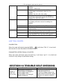
SECTIOIN 12 TROUBLE SELF CHECKING
Problem
Display is
blank, No
turn on test
Possible cause
Mains power is turned off
Power supply not plugged in
Power supply faulty
Internal battery not charged
Display turned off
Common solutions
Check power is going to the
scale and switch is on.
Verify the voltage going to the
scale matches the power supply
labels on the power module or
scale.
14
CTB serial bench scale service manual
Display
blank
after turn on
test,
Error
message
Display is
locked
OL or FULL
appears on
display
UL or NULL
displayed
Display is
unstable
Pan not installed
Unstable weight
Load cell damaged
Mechanics damaged
Maximum capacity exceeded
Load Cell or mechanics
damaged
Power supply faulty
Weight on scale below
permissible limit
Pan has been removed
Pan support not seated properly
Power supply faulty
Load Cell or mechanics
damaged
Drafts or air currents
Obstruction under pan
Sample is moving (animal
weighing)
Vibrations through table
Temperature changed
dramatically
Power supply faulty
Check the pans are installed
correctly.
Try turning the scale on again.
Check the pans are installed
correctly.
Try turning the scale on again.
Check the pans are installed
correctly.
Try pressing Zero key.
Try turning the scale on again.
Verify the scale is in a
acceptable location and on a
good table.
Verify the power supply is
correct for the scale.
Weight
value
incorrect
Calibration error, Recalibrate
Linearity error, set Linearity
Unit calibrated with inaccurate
weight
Balance not level
Obstruction between sample and
cover
Wrong unit of weight displayed
Calibrate again, paying special
attention to the mass used, the
stability of the scale, and the
weighing units required.
If linearity can be set by the user
it will be described in the user
manual.
Check pan is installed correctly.
Verify installation is acceptable.
Cannot use
Full
Capacity
Over load Stops hitting pan
support or hitting bottom of load
cell
Shipping screw not removed if
applicable
Electronic problem on A/D
Parameters set incorrectly
Load Cell or mechanics
Damaged
Look for obstruction under pan,
shipping screws, and verify pan
installation.
Check the weighing units used.
Not Linear
Off Center
Overload stops hitting too soon
Load cell or mechanics damaged
A/D damaged
Adjust mechanics
Overload Stops not correct
Look for obstruction under pan,
shipping screws, and verify pan
installation.
If linearity can be set by the user
it will be described in the user
manual.
Look for obstruction under pan,
shipping screws, and verify pan
15
CTB serial bench scale service manual
Loading
error
Battery will
not
charge
Overload Stops not correct
Load Cell damaged
Mains voltage not present or too
low
Charging circuit failure
Battery Failure
shipping screws, and verify pan
installation.
Verify the batteries are
rechargeable types.
Check power supply voltage is
correct.
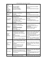
SECTIOIN 13 TROUBLESHOOTING
START
CHK power
switch
and connector
Replace power switch or
Battery
voltage>5.5V
T10 pin 3
output5V
Charging the battery
immediately
or replace the battery
CHK T10 and around circuit
CHK U1 pin9
High level when power
on
And return to low level
CHK U1 and around circuit
CHK ST
(11.0592MHz)
13
CHK ST and around
circuit
2 no display
CHK U1 START
and around circuit
CHK LCD
break?
16
Replace LCD
CTB serial bench scale service manual
13
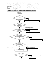
3 Can’t charge the battery
START
Battery bad?
(battery
Replace battery
Fuse open?
Replace the fuse and solve
the problem (like
transformer bad)
Cut the circuit,
then CHK
transformer
output >10V
Replace
transformer
Open U5
pin11/12,
CHK BR1 output
>12V
Restore the circuit,
CHK U5 pin2
output>7V
Y
CHK BR and around
circuit
N
CHK M/B U5 and around
circuit
CHK M/B D1, R7 and around circuit
17
CTB serial bench scale service manual
13
4 Can’t weigh
START
CHK whether can
show internal
counts
N
N
CHK M/B
AU1
pin15=5V
Y
Y
Add load on
pan, CHK
counts raise
N
Y
Do calibrate
CHK power circuit
CHK load cell input circuit
Add load on pan,
CHK output
between AU1 pin1
and pin2 signal
change
Y
Check load cell
N
CHK AU1 and around circuit
18
CTB serial bench scale service manual
13
5 unstable
START
OK after
warn
N
Load cell
and bracket
touch
something
Y
Dispel humidity
Y
Solve touch problem
N
CHK M/B AU1 and around
circuit
13
6 Can’t use keyboard
19
CTB serial bench scale service manual
START
Find the line for
useless key, short
and open it, CHK the
scale accept this
Y
Replace keyboard
N
CHK U1 and around circuit
Note: M/B means main board, D/B means display board.
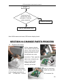
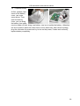
SECTION 14 CHANGE PARTS PROCESS
14
1 Replace main board
At first, release indicator
from indicator bracket, like
picture, then release 6 pcs
screw from back cover of
the indicator use cross
srew driver. Then, open the
back cover, release 4 pcs
screw of main board,
release main board
carefully, pull out all
connector on the main board,
out main board carefully. Then
then you can bring
install the new main
board, plug all connector at
last
ATTENTION CH3.96
4P connector (for
20
CTB serial bench scale service manual
power) must be pulled out at first and plug at last After check anything try to turn
on the power if anything is OK close the back cover replace main board
completely.
14
2 replace load cell
At first, use internal
hexagon screw driver
release 4 pcs screw from
upper bracket, remove
upper bracket, then release
4 pcs screw from bottom
bracket, by this way, you
can remove load cell now.
Use iron to solder cable for
load cell, remove cable
from connector, then pull
cable from pole. Bring new
load cell, let cable through
pole, solder the cable to
connector. Now, you can fix 8 pcs internal hexagon screw again (Attention: fix tight
enough as you can ). Then you can check and adjust corner and overload stop use
file and internal hexagon screw driver. After check anything, try to turn on the power
and show the internal counts, if internal counts looks OK, close the pan, change load
cell completely.
14
3 replace MPU
At first, release indicator
from indicator bracket, like
picture, then release 6 pcs
screw from back cover of
the indicator use cross srew
driver. Then, open the back
cover, pull of the connector for power (CH3.96 4P), use special IC kit or minus screw
driver to put up the MPU
from DIP40 socket
(Attention: please don’t let
the IC pin tilt), then use the
new MPU plug into DIP40
socket (Attention: please
note the gap direction), after
check anything is OK, plug the power connector (CH3.96 4P), try to turn on the
power, if scale work correctly, replace MPU completely.
21
CTB serial bench scale service manual
14
4 replace battery
At first, release 4 pcs
screw of the battery
cover. use cross
screw driver, Then,
open the battery
cover, you can bring
the battery from scale,
use iron solder off wire, bring new battery, use iron to solder the battery, (Attention:
red line to positive electrode, black line to minus electrode), after check anything,
plug the connector for power and try to turn on the power, if scale work correctly,
replace battery completely.
22
CTB serial bench scale service manual
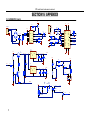
SECTION15 APPENDIX
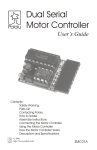
15.1 SCHEMATIC (main)
VAC
BR1
2
VAC
3
C5
3K
R6
3.9K
25V/470UF
VB
10
3
LOADCELL
VCH
S+
10K
R5
13 C10
201
S-
10K
LM723CN
AR8
AC11
0.022UF
10K
AR5
10K
AR1
18
17
10K
AR6
10K
R4
4
E+
AR7
AC10
0.022UF
AC12
0.022UF
10K
AC13
0.022UF
3
4
1
2
20
19
7
8
1
VIN
VOUT
3
AC12
100UF/25V
2K
R20
5.1K
1
470UF/25V104
VIN
R18
1.5K
VOUT
CS
A1N1+
A1N1A1N2+
A1N2A0
A1
SDI
SDO
SCLK
20K
CS
13
12
SDI
SDO
11
SCLK
CS5532
3
10K
R11
T3
9014
AVCC
AC4
AC6
VAC
R10
AC8
T5
9015
100K
T4
9015
R14
100K
R9
10K
R13
1K
R12
470UF/25V 6.8UF/25V100UF/25V
LED
1K
VGND
R17
4.9152
14
VCH
6.8UF/25V
G
R19
3.9K
15
OSC2
OSC1
C1
C2
AC14
D2
IN4736
2
T6
9014
C17
T8
LM2931
GND
R21
5.1K
R16
RST
AST2
9
10
DVCC
C18
2
KEY
GND
T7
8550
VREF+
VREF-
6
T10
LM2931
VB
AU1
VD+
D1
R8
2
AR2
10K
R
4
V+ VOUT
VC
VREF
CL
N.I.
NC
CS
NC
NC
INI
VZ
VCOMP
AC9
104
DGND
R7
10
VCC
16
VB
U5
SS+
GND
EE+
VA+
VAC
12
11
6
5
14
8
1
9
7
1
2
3
4
5
VA-
100K
1
1
2
3
4
T2
TIP31C
5
E+
R3
POWER
CHECK
R22
3K
VCC
T8
C14
6.8uf/16v
R23
100
C13
0.047uf
3
4
2
1
OUT
EL2
TR1
GND
EL1
T9
9014
R23
2K
BL
23
CTB serial bench scale service manual
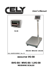
15.2 SCHEMATIC (display)
KEY
1
2
3
4
5
6
7
8
VCC
1
KEY1
KEY2
KEY3
KEY4
KEY5
VB
KON
2
R2
T1
9014
BUZZ
2K
RP3
VCC
VCC
U1
1
2
3
4
5
6
7
8
9
KEEP1
2
3
4
5
6
7
8
103G
5532.CS
5532.SDI
13
12
15
14
R1
VCC
C2
20P
C1
20P
C19
10K
ST1
11.0592
R15
VCC
10UF/10V
P10/T
P11/T
P12
P13
P14
P15
P16
P17
P00
P01
P02
P03
P04
P05
P06
P07
INT1
INT0
P20
P21
P22
P23
P24
P25
P26
P27
T1
T0
31
EA/VP
19
18
39
38
37
36
35
34
33
32
BL
21
22
23
24
25
26
27
28
5532.SCLK
5532.SDO
SDA
SCL
WP
PCH1
PCH2
CS
RD
WR
DATA
RP2
9
8
7
6
5
4
3
2
1
X1
X2
RESET 9
10 RXD
11 TXD
30
29
RXD
TXD
ALE/P
PSEN
RD
WR
10K
103G
LCD
U4
SEG27 13
SEG26 14
SEG25 15
SEG24 16
SEG23 17
SEG22 18
19
20
COM3 21
COM2 22
COM1 23
COM0 24
12
11
10
9
8
7
6
5
4
3
2
1
12
11
10
9
8
7
6
5
4 SEG28
3 SEG29
2 SEG30
1 SEG31
R30
VCC
VCC
1K
103G
RESET
17
16
RP1
1
2
3
4
5
6
7
8
9
U2
5
8032
6
7
VCC
VCC
SDA
VSS
A2
A1
WP
A0
SCL
8
4
3
2
1
SEG7 1
SEG6 2
SEG5 3
SEG4 4
SEG3 5
SEG2 6
SEG1 7
SEG0 8
1621.CS 9
RD
10
WR 11
DATA 12
13
14
15
16
17
18
19
20
COM0 21
COM1 22
COM2 23
COM3 24
HT24LC02
SEG7
SEG6
SEG5
SEG4
SEG3
SEG2
SEG1
SEG0
CS
RD
WR
DATA
VSS
OSC0
OSC1
VLCD
VDD
IRQ
BZ
BZ
COM0
COM1
COM2
COM3
SEG8
SEG9
SEG10
SEG11
SEG12
SEG13
SEG14
SEG15
SEG16
SEG17
SEG18
SEG19
SEG20
SEG21
SEG22
SEG23
SEG24
SEG25
SEG26
SEG27
SEG28
SEG29
SEG30
SEG31
48
47
46
45
44
43
42
41
40
39
38
37
36
35
34
33
32
31
30
29
28
27
26
25
SEG22
SEG23
SEG24
SEG25
SEG26
SEG27
SEG28
SEG29
SEG30
SEG31
1621B
330K
R26
VB
C6
R27 240K
VCC
VAC
R29
20K
R28
20K
R24
300K R25
220K
U3
LM358
1
PCH1
3
U3 LM358
6
7
5
U8
VCC
2
PCH2
1
2
3
4
T
25V/10UF
C7
25V/10UF
C8
25V/10UF
R
SERIAL
C9
2
1
3
4
5
7
8
6
V+
VCC
C1+
T1OUT
C1R1IN
C2+
R1OUT
C2T1IN
T2OUT T2IN
R2IN R2OUT
VGND
25V/10UF
MAX232
16
14
13
12
11
10
9
15
VCC
TXD
RXD
23
CTB serial bench scale service manual
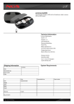
15. 3 PARTS DRAWING
2
5
CTB serial bench scale service manual
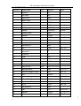
15. 4 PARTS LIST
Parts No.
Parts name
QTY
Material
1
overlay
1
PC
2
iron plate
1
iron
3
Top cover
1
ABS
4
Main PCBA
1
5
washer
4
EPDM
6
screw
4
S18C
7
Battery holder
1
SUS#304
8
Battery
1
Lead acid
9
Bottom cover
1
ABS
10
washer
6
EPDM
11
screw
6
S18C
12
Neck parts 1
1
ABS
13
Neck parts 2
1
ABS
14
Neck parts 3
1
ABS
15
1
S18C
1
Al
17
nut
Load cell upper
supporter
Load cell
1
Al
18
Pole
1
SST
19
Bottom bracket
1
Al
20
Overload stop screw
4
S18C
21
Pole bracket
Q235
22
Mat for pole
steel
189 x 132 x 0.8
23
Spring washer
3
steel
10 x 6 x 2
24
internal hexagon screw
3
35#
M6 x 12
25
feet
4
Rubber
26
internal hexagon screw
4
35#
M12 x 45
27
internal hexagon screw
4
35#
M12 x 45
28
washer
1
S18C
12 x 7 x 1.2
29
screw
1
S18C
M3 x 20
30
Neck parts 4
1
ABS
31
pan
1
SST
420 x 520
32
washer
2
EPDM
8 x 3.5 x 1.2
33
screw
2
S18C
M3 x 8
16
Spec
M4 x 8
6V/4Ah
M4 x 20
M6 x 3.5
M8 x 7
2
5
CTB serial bench scale service manual
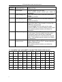
15. 5 ERROR CODES
ERROR
DESCRIPTION
CODES
- - - - Over range
Err 1
Date Setting Error
Err 2
Time Setting Error
Err 4
Zero Setting Error
Err 6
A/D out of range
Err 9
Unstable, can’t
return to zero
RESOLUTION
Remove weight from the scale.
If the problem persist contact your dealer for
assistance.
Enter date using correct format and reasonable
values.
Format: yy:mm:dd
Enter time using correct format and reasonable
values.
Format: hh:mm:ss
The scale was outside the normal zero setting
range either when it was turned on or when the
ZERO key was pressed.
Remove weight from the scale and try again.
Use the TARE key to set the display to zero value.
If the problem persist contact your dealer for
assistance.
The values from the A/D converter are outside the
normal range. Remove weight from the scale if
overloaded, make sure the pan is attached.
Indicates the load cell or the electronics may be
faulty. If the problem persist contact your dealer
for assistance.
When turn on the power, if internal counts is not
stable, display will have “Err 9”, please check the
platform and load cell.
If the problem persist contact your dealer for
assistance.
15. 6 NUMERIC AND ALPHABETIC CHARACTERS DISPLAYED ON LCD
I
0
1
2
3
4
5
6
7
8
9
0
1
2
3
4
5
6
7
8
9
A
B
C
D
E
F
G
H
I
J
A
B
C
D
E
F
G
H
I
J
K
L
M
N
O
P
Q
R
S
T
K
L
M
N
O
P
Q
R
S
T
U
V
W
X
Y
Z
U
V
W
X
Y
Z
!


![[17] User`s Manual ver. 2.0.2](http://vs1.manualzilla.com/store/data/005765389_1-e376d351ef2708f30fcfdc5f98b9ba18-150x150.png)