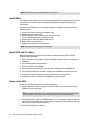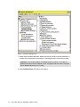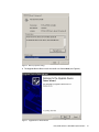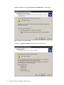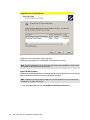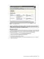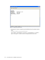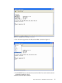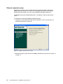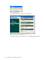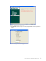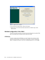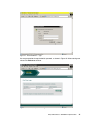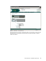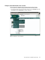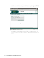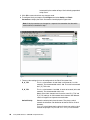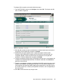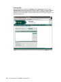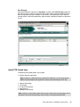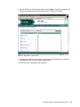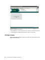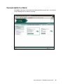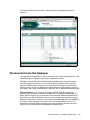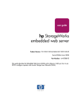
1
Redbooks Paper Jon Tate Cameron Hildebran Entry SAN Switches: SAN16M-2 Implementation Overview This paper details the basic installation and configuration of an entry-level SAN with the IBM® TotalStorage® SAN16M-2 Express Model fabric switch. In less complex SAN environments, with fewer servers and storage arrays, single switch or dual cascaded switches offer redundancy and performance with minimal administration and lower cost than larger directors. For this example we use two IBM Thinkcentre machines running Windows® as host servers. To connect to the 16M-2 switches utilized in this paper the Windows servers use QLogic QLA2300 HBAs. Storage is supplied by an IBM TotalStorage DS400 with six 36.4 GB disk drives. Further information about the 16M-2 (including interoperability matrix) can be found at the IBM storage Web site: http://www-03.ibm.com/servers/storage/san/m_type/san16m-2/express/index.html Before you begin Make sure that you: Have IP addresses ready to assign to the 16M-2 switches and the DS400 controllers. Have Ethernet cables ready to integrate the SAN with your network switch. This is the switch the servers are connected to and will be used in the SAN installation. Know the servers’ host names (defined during server installation) and be ready to assign a name to the SAN. Have an unzip utility such as PKZIP or WinZip. If installing the DS400 and 16M-2 switches in a rack, follow the guide Rack Installation Instructions for the DS400 system. © Copyright IBM Corp. 2006. All rights reserved. ibm.com/redbooks 1 Note: Do not turn on power to the hardware at this point. Install HBAs This step assumes that the servers are already configured with the operating system and are connected to the network switch according to the appropriate network settings for your environment. Installation of the HBAs vary by server type. However, the following steps summarize the general process: 1. 2. 3. 4. 5. 6. 7. Power off the server and remove the power cable. Remove the server outer cover. Remove the blank cover (if present) from the PCI bus slots. Press the HBA board until it is seated in the slot. Repeat steps 3 and 4 for additional HBA boards. Replace the server outer cover. Repeat these steps for the second server. Note: Do not power on that servers at this point. Install SFPs and FC cables Remove the protective cap from the SFP modules. Make the following SFP and Fibre Channel cable connections: 1. SFPs into the back of the 16M-2 switches. Begin with the port marked 1 and continue in sequence. 2. Fibre Channel cables into switch SFPs. 3. SFPs into the back of the DS400. 4. Two Fibre Channel cables from each of the 16M-2 switches into the DS400 SFPs. 5. Fibre Channel cables from the 16M-2 switches into the HBAs of the two host servers. 6. One Ethernet cable from the back of each 16M-2 switch to network switch. 7. Two Ethernet cables from the back of DS400 to the network switch. Power on the SAN Follow the steps below to switch on the SAN components: 1. Connect the power cables to the 16M-2 switches. Power on is confirmed by the Power LED on the back of the switch. Note: The power cord plug serves as the only disconnect device on the 16M-2 switch. To cycle power on the switch, you must remove and reconnect the power cord. 2. Connect the power cables for the DS400 system. Turn on the power switches located on the back of each controller one at a time. When the controllers are booted and ready, the indicator light (top left LED) will illuminate. 3. Connect and power on the servers. 2 Entry SAN Switches: SAN16M-2 Implementation Important: When the servers are first switched on they will launch the Found New Hardware wizard application. Cancel out of this wizard. Installation of the HBAs is covered in the next section. Download and install software The next step is to download and install the latest software for each component from the IBM storage Web site: http://ibm.com/storage/support/san The software necessary for this implementation is: HBA drivers Latest DS400 firmware IBM Diagnostic and Configuration Utility FAStT MSJ or SANsurfer Pro Windows Multipath MPIO ServeRAID™ Manager Management Station Note: Designate one server as the management server for the storage. All software should be downloaded and installed to the management server, except the HBA drivers, which will be installed on both servers. Do not immediately install the software after download. Some software is installed later in the process. HBA drivers (Windows 2000) After powering on the servers the HBAs will be recognized and the New Hardware Found wizard will open. Cancel out of this process. Follow these instructions to install the HBA drivers: 1. From the support Web site select the link for HBA drivers. 2. A message box appears warning that you are leaving the IBM Storage Web site. Click Continue. 3. Follow the instructions to download the file. 4. Unzip the file contents into a temporary directory. 5. Run the Install.exe file. The HBA drivers will automatically install. 6. From the desktop, go to My Computer → Manage, and select Device Manager (see Figure 1 on page 4). Entry SAN Switches: SAN16M-2 Implementation 3 Figure 1 The Device Manager Tool 7. Under SCSI and RAID Controllers, double-click one of the Fibre Channel Controllers. It should have an exclamation mark next to it, indicating that there is no driver installed. Important: If any of your adapters are labeled QL2xxx (or similar, as in Figure 1), perform these steps with that adapter as well. An adapter with that name is using the built-in Windows drivers that do not work. 8. Select Reinstall Driver (see Figure 2 on page 5). 4 Entry SAN Switches: SAN16M-2 Implementation Figure 2 Device properties dialog 9. The Upgrade Device Driver Install wizard will start. Select Next (see Figure 3). Figure 3 Upgrade Device Driver Wizard Entry SAN Switches: SAN16M-2 Implementation 5 10.Select the option starting with Search for a suitable driver... (see Figure 4). Figure 4 Driver source selection dialog 11.Select only Specify a location on the next screen (see Figure 5). Figure 5 Locate Driver Files first dialog 6 Entry SAN Switches: SAN16M-2 Implementation 12.In the next dialog, use the Browse function to select the folder where you unzipped the driver file. 13.Windows may state that it has drivers that are a closer match than the one you selected. This is not correct. You must select Install one of the other drivers (see Figure 6). Figure 6 Driver File Results dialog 14.Select the driver with the source of the directory you unzipped the drivers in. Do not select the driver in the windows directory (see Figure 7 on page 8). Make sure that you check the path of the driver you are installing. Entry SAN Switches: SAN16M-2 Implementation 7 Figure 7 Driver Files Found dialog 15.Bypass any warnings about a digital signature. 16.Restart when prompted. If not prompted, restart the server anyway. Note: Install the HBA drivers on both servers. Instructions are provided for a single server and should be repeated for the second server. Latest DS400 firmware IBM updates the DS400 controller firmware periodically for peak performance of the storage. Obtain the updated controller firmware by following these steps. Note: To obtain the firmware from the Web site, you are required to fill out a short export control form, as shown in Figure 8. 1. From the support Web site click the DS400 Dual Controller Firmware link. 8 Entry SAN Switches: SAN16M-2 Implementation Figure 8 DS400 Firmware export control 2. A message box appears warning that you are leaving the IBM Storage Web site, as shown in Figure 9. Click Continue. Figure 9 DS400 firmware download redirect 3. Select the appropriate link and follow the instructions to download the file. Entry SAN Switches: SAN16M-2 Implementation 9 4. Once the file is downloaded, unzip it using any unzip utility and store in a temporary folder. Note: Do not attempt to install firmware yet. ServeRAID software is required to update the firmware. This step is covered in a subsequent section of this paper. IBM Diagnostic and Configuration Utilities You may encounter either one of the following utilities. FAStT MSJ The IBM FAStT MSJ utility enables a user to quickly run diagnostics and basic functions through an easy-to-use GUI. 1. From the support Web site select the IBM Configuration and Diagnostics Utility FAStT MSJ link. 2. Follow the instructions to download and install the software. Note: The software will download via IBM Download Director. Once the download is complete close IBM Download Director application and install FAStT MSJ using the default settings. SANsurfer Pro The QLogic SANsurfer Pro utility enables a user to quickly run diagnostics and basic functions through an easy-to-use GUI. Once you download it, run the .exe file and follow the dialog boxes. SANsurfer pro has superseded FAStT MSJ. Important: During the SANsurfer installation, you may be asked whether you want to install failover protection. You must answer no. No IBM storage array at the time of writing uses the QLogic failover driver with Windows. Windows Multipath MPIO Windows Multipath MPIO works behind the scenes with IBM ServeRAID. In a true multipath environment MPIO works with the operating system to define redundant paths to data. If a path malfunctions, MPIO enables the operating system to switch to a redundant path. Follow the instructions below to install Windows Multipath MPIO: 1. From the support Web site select the Windows Multipath MPIO link. 2. A message box appears warning that you are leaving the IBM Storage Web site. Click Continue. 3. Follow the instructions to download and unzip the file. 4. Install the MPIO software. ServeRAID Manager The ServeRAID software is included in CD form with the DS400 controller. It can also be downloaded from the same page as the DS400 firmware. This is shown in Figure 10 on page 11. 10 Entry SAN Switches: SAN16M-2 Implementation Figure 10 ServeRAID download Note: The ServeRAID Manager will be installed in a subsequent section after the basic configuration of the 16M-2 switch and DS400 controller. Management Station The Management Station software is downloaded from the same page as the ServeRAID CD image and the DS400 firmware. It works in conjunction with ServeRAID, allowing a server to be added to ServeRAID as a Management Station for SAN-connected storage. 1. From the support Web site select the Management Station link. 2. Follow the instructions to download and unzip the file. 3. Install the Management Station software. 4. During the install process define a user name and password for the server, as shown in Figure 11 on page 12. Entry SAN Switches: SAN16M-2 Implementation 11 Figure 11 Management Station Username and Password This user name and password will be utilized later for adding the server to the ServeRAID Manager. Initial configuration of the 16M-2 switch The initial configuration of the 16M-2 switch can be done through a network or through a serial connection. Serial connection setup Follow the instructions below for the basic setup of the 16M-2 switch via serial connection: 1. Connect the supplied RS232 cable from the front of the switch to the host server or a maintenance workstation. 2. Open a terminal session through an emulation program such as Microsoft® HyperTerminal. 3. Select an appropriate name for the connection and click the OK button. 4. On the resulting screen make selections as shown in Figure 12 on page 13, and click OK. 12 Entry SAN Switches: SAN16M-2 Implementation Figure 12 16M-2 setup 5. At the prompt, type password and press Enter. password is the default password for a new 16M-2 switch. 6. At the C> prompt type ipconfig and press Enter. The following information is displayed, as illustrated in Figure 13 on page 14: – – – – MAC address IP address (default 10.1.1.10) Subnet Mask (default 255.0.0.0) Gateway address (default 0.0.0.0) Entry SAN Switches: SAN16M-2 Implementation 13 Figure 13 Default switch network values 7. To change the IP, subnet, and gateway, type the following string at the prompt and press Enter: ipconfig xxx.xxx.xxx yyy.yyy.yyy zzz.zzz.zzz The IP address is represented by x, the subnet is y, and the gateway is z, as shown in Figure 14 on page 15, if a field is to remain unchanged enter the current value. 14 Entry SAN Switches: SAN16M-2 Implementation Figure 14 Changing network settings on the switch 8. From the terminal application click File, and then Exit, as shown in Figure 15. Figure 15 Close HyperTerminal 9. The IML/RESET button is found on the back of the 16M-2. Push and hold this button for 10 seconds to reboot the switch. 10.Connect the switch to the network. Entry SAN Switches: SAN16M-2 Implementation 15 Ethernet connection setup Alternatively, the switch can be configured using the supplied crossover cable and the SANplicity wizard. The wizard is a small Java™ application that requires Java Runtime Environment (JRE) Version 1.3 or later, and is qualified for Windows and Solaris™. The SANplicity wizard file, SANplicityWizard.jar, is included on a CD that ships with the switch. To configure the switch using SANplicity follow these steps: 1. If necessary, unzip the file and launch the wizard from the .jar file. This launches the welcome screen shown in Figure 16. Figure 16 SANplicity wizard welcome screen 2. Read the welcome screen and then click Next to proceed to the step shown in Figure 17 on page 17. 16 Entry SAN Switches: SAN16M-2 Implementation Figure 17 SANplicity wizard unpack screen 3. After ensuring that the hardware is unpacked and powered up, click Next to proceed to test the connection, as shown in Figure 18. Figure 18 SANplicity wizard connection screen 4. Plug in the cross-over cable as instructed and click the Test Connection button. Once the test is successful click OK in the pop-up box, as shown in Figure 19 on page 18. Note: If a software firewall is installed, the javaw.exe process may need to be authorized. Entry SAN Switches: SAN16M-2 Implementation 17 Figure 19 Connection tested 5. Click Next to proceed to enter settings, as shown in Figure 20. Figure 20 SANplicity wizard switch settings screen 6. Complete all fields with the correct values, review, and click Next to proceed to activation. 18 Entry SAN Switches: SAN16M-2 Implementation Figure 21 SANplicity wizard activation screen 7. Click Activate, as shown in Figure 21, and the progress window shown in Figure 22 will appear. Figure 22 SANplicity wizard activation progress Entry SAN Switches: SAN16M-2 Implementation 19 Figure 23 SANplicity wizard completion 8. Once finalized, the window shown in Figure 23 will appear. 9. Remove the cross-over cable and connect the switch to the network using a normal Ethernet cable. Detailed configuration of the 16M-2 The switch is now setup and can be accessed for advanced configuration using either EFCM Basic or the EFCM server. EFCM Basic ships on CD with the switch. EFCM Basic To continue configuration with EFCM Basic, type the IP address of the switch into a Web browser on the same network. This will bring up a login prompt, as shown in Figure 24 on page 21. The default user name is Administrator and the password is password. Click OK. 20 Entry SAN Switches: SAN16M-2 Implementation Figure 24 Initial EFCM Basic - login You are prompted to change the default password, as shown in Figure 25. After entering new values click Activate to continue. Figure 25 EFCM Basic - password change Entry SAN Switches: SAN16M-2 Implementation 21 After login the switch overview statistics are displayed, as shown in Figure 26. Figure 26 EFCM Basic - switch overview More details of the switch, as shown in Figure 27 on page 23, are viewed by clicking the Switch Details button. 22 Entry SAN Switches: SAN16M-2 Implementation Figure 27 EFCM Basic - switch details view Detailed information and statistics, configuration options, security settings, maintenance and upgrade features are accessed by clicking the menus at the top of the page, as shown in Figure 28 on page 24. Entry SAN Switches: SAN16M-2 Implementation 23 Figure 28 Menu options 24 Entry SAN Switches: SAN16M-2 Implementation Configure switch identification, date, and time To allow management workstations to obtain product data from the switch, the Name, Location, and Contact variables must be set. Take these steps to set these variables: 1. From the Switch Details view of the EFCM Basic interface, click the Configure menu and select Switch, and then Identification, as shown in Figure 29. Figure 29 EFCM Basic - switch configuration Entry SAN Switches: SAN16M-2 Implementation 25 2. This brings up the Identification view. Enter a product name and description, the physical location, and the name of a contact person if desired, as displayed in Figure 30. Click OK. Figure 30 EFCM Basic - Identification view 3. Click Configure, and select Switch, then Date & Time, to change these settings. The Date Time view displays, as in Figure 31 on page 27. Adjust the date and time, and then click OK. 26 Entry SAN Switches: SAN16M-2 Implementation Figure 31 EFCM Basic - date and time Entry SAN Switches: SAN16M-2 Implementation 27 Configure switch and fabric parameters Follow these steps to configure the operating parameters of the 16M-2 switch: 1. Before parameters can be configured the switch must be taken offline. In EFCM Basic click Maintenance and select Switch. This displays the Switch view, shown in Figure 32. Figure 32 EFCM Basic - maintenance 2. Click Deactivate to put the switch offline. 28 Entry SAN Switches: SAN16M-2 Implementation 3. Once the switch is offline click Configure, then select Switch and Parameters to display the Parameters view, shown in Figure 33. Figure 33 EFCM Basic - switch parameters 4. Multiple settings are changed via the Parameters view: Insistent Domain ID When enabled, the value in the Preferred Domain ID field is the active domain ID upon fabric initialization. Rerouting Delay When enabled, traffic through the fabric is delayed by the user-specified error detect time-out value. This delay ensures that Fibre Channel frames are delivered in order. Domain RSCN When enabled, attached devices can register to receive notification when other devices change state. Suppress RSCN When enabled, RSCNs are not transmitted when a zone set is activated. Limited Fabric RSCN When enabled, RSCNs are not transmitted after a product initial program load. Zone FlexPars When enabled, zone FlexPars isolate and prevent fabric-format RSCNs from propagating to devices in zones that are not impacted. Preferred Domain ID This is a value between 1 and 31 that uniquely identifies each fabric element. ISL FSPF Cost This calculates fabric shortest path first cost. By Port Speed is determined by port (ISL) speed. Cost is inversely proportional to speed. Ignore Port Speed ignores ISL speed and determines the Entry SAN Switches: SAN16M-2 Implementation 29 fastest path by the number of hops. Cost is directly proportional to hop count. 5. Click OK to save and activate any changes made. 6. To configure fabric parameters click Configure and select Switch and Fabric Parameters to display the Fabric Parameters view displayed in Figure 0-34. Note: If fabric parameters are changed at a separate time remember that the switch must be offline, as detailed in step 1. Figure 0-34 EFCM Basic - Fabric Parameters view 7. There are four settings that can be configured via the Fabric Parameter view: R_A_TOV This is a value between 10 and 1200, in milliseconds (1 to 120 seconds). The recommended value is 100. The value must exceed the E_D_TOV value. E_D_TOV This is a value between 2 and 600, in tenths of seconds (0.2 to 60 seconds). The recommended value is 20. Note that the fabric elements must have the same R_A_TOV and E_D_TOV settings. An ISL between fabric elements with different values will segment and prevent communication. Switch Priority 30 Select the switch priority from the menu. The primary switch controls the allocation and distribution of domain IDs for all fabric elements. Principal is the highest priority setting. At least one switch in fabric must be the principal. Default and Never Principal are the other Entry SAN Switches: SAN16M-2 Implementation choices. If all switches are set to Never Principal, all ISLs will segment. Interop Mode Select the switch operating mode from the menu. This setting effects management mode, not port operation. McDATA Fabric 1.0 should be selected if the switch is fabric-attached only to other IBM directors or switches operating in McDATA fabric mode. Open Fabric 1.0 (default) should be selected for managing heterogeneous fabrics and if the switch is fabric-attached to other open-fabric compliant switches. 8. Click OK to save and activate any changes made. 9. Set the switch status to online by clicking Activate from the Switch view outlined in step 1. Port settings In this section we discuss the port settings. Configure basic port settings Follow these steps to configure basic port information: 1. Click Configure, then select Ports and Basic Info to display the Basic Information view shown in Figure 35. Figure 35 EFCM Basic - basic port information 2. For each port to be configured, type an alphanumeric (maximum 24 characters) name in the Name field. Entry SAN Switches: SAN16M-2 Implementation 31 3. Click the check box in the Blocked column to block or unblock a port. The ports are unblocked by default. 4. Click the check box in the FAN column to enable or disable fabric address notification (FAN). The ports are enabled by default. When enabled, an FL_Port transmits FAN frames after loop initialization to verify FC-AL devices are still logged in. 5. Select from the menu in the Type column to designate port type: F_Port E_Port G_Port GX_Port FX_Port Fabric port Expansion port Generic port Generic mixed port Fabric mixed port 6. Select menu in the Speed column to designate port transmission rate. Options are 1, 2, or 4 Gbps, and negotiate. 7. Click OK to save and activate any changes. Configure port BB_Credit The 16M-2 switch provides a port buffer pool of 150 receive BB_Credits. Each port can be assigned between 2 and 120 credits, provided the total credits allocated to all ports do not exceed the total of 150 available. The default is 6 credits per port. To configure port receive BB_Credits follow these steps: 1. Set all ports offline, as outlined in steps one and two in “Configure switch and fabric parameters” on page 28. If only specific ports are being configured they can be individually blocked as in step three of “Configure basic port settings” on page 31. 2. From the EFCM Basic interface click Configure, then select Ports and RX BB_Credit to display the RX BB_Credit view shown in Figure 36 on page 33. 32 Entry SAN Switches: SAN16M-2 Implementation Figure 36 Ports - BB_Credit setting 3. Perform one of the following: – Click Default. This sets all offline ports to default values. – Type the desired value in the RX BB_Credit column to set a non-default value. 4. Click OK to save and activate any changes. 5. Return all, or user-specified, ports to online status. Configure port NPIV NPIV allows multiple (up to 256) Fibre Channel addresses to be assigned to a node (N_Port). Note: The NPIV feature must be purchased separately and installed as in section “Install PFE license keys” on page 47 to take advantage of this functionality. For more details on availability and installation of separately purchased keys refer to the IBM TotalStorage SAN16M-2 Installation and Service Manual. To configure ports for NPIV connectivity follow these steps: 1. From the EFCM Basic interface click Configure and select Ports and NPIV to display the NPIV view. If the NPIV license has not been installed the display will look like Figure 37 on page 34. Entry SAN Switches: SAN16M-2 Implementation 33 Figure 37 Ports - NPIV not installed 2. Once the NPIV PFE key is installed the NPIV view will reflect that ports are accessible, as in Figure 38 on page 35. 34 Entry SAN Switches: SAN16M-2 Implementation Figure 38 Ports - NPIV installed 3. Click Enable to activate product NPIV operation. 4. To set a port to a user-specified value, type the desired value (1 through 256) in the Login column. 5. Click OK to save and activate any changes made. Configure SNMP To configure names and write authorizations, addresses, and user datagram protocol (UDP) port numbers for SNMP trap message recipients, follow these steps to configure recipient workstations: 1. From the EFCM Basic interface click Configure, then select SNMP, to display the SNMP view, as shown in Figure 39 on page 36. Entry SAN Switches: SAN16M-2 Implementation 35 Figure 39 EFCM Basic - SNMP view a. Click Enable to activate the installed SNMP agent, if it is not already enabled. b. Select the appropriate Fibre Alliance management information base (FA MIB) from the FA MIB Version drop-down list. Valid selections are FA MIB Version 3.0 or FA MIB Version 3.1. c. Click the Enable Authentication Traps check box to enable transmission of SNMP trap messages to recipients. d. For each configured recipient, type a community name (32 alphanumeric characters or less) in the Name field. The name is incorporated in SNMP trap messages to ensure against unauthorized viewing. e. Check the box in the Write Auth column to enable write authorization for the trap recipient (disabled by default). When enabled, a configured user can change sysContact, sysName, and sysLocation SNMP variables. f. Type the IP address or DNS host name of the trap recipient (SNMP management workstation) in the Trap Recipient field. We recommend that the IP address be used. g. Type a decimal port number in the UDP Port Number field to specify the UDP port number. 7 2. Click OK to save and activate any changes. Configure SSL encryption The SSL protocol encrypts Internet communications. The SSL protocol uses key encryption and includes a digital certificate enabling server authentication and SSL session initialization. 36 Entry SAN Switches: SAN16M-2 Implementation To configure SSL encryption on the switch follow these steps: 1. From the EFCM Basic interface click Configure, then select SSL. This displays the SSL view, as shown in Figure 40. Figure 40 EFCM Basic - SSL view 2. With Web SSL enabled, all data transmitted over an authenticated Internet connection is encrypted. To initiate Web SSL encryption click Enable. 3. Software SSL encryption enables use of an application program interface (API) connection. With software SSL enabled, secure and unsecure communications are acceptable. However, unsecure communications are directed to an encrypted API connection. To initiate software SSL encryption click Enable. 4. To define the expiration period (in days) of the digital certificate, type a value between 30 and 3650 in the field below New Certificate. The default is 365 days. Click Generate to generate a new certificate. 5. To define a renegotiation parameter (in megabytes) for the SSL session key, type a value between 50 and 10000 in the Renegotiate after field. This value defines the MB of data transmitted over the connection before triggering the regeneration of a new SSL session key. An SSL session key is valid only during the SSL connection, and is renegotiated per the value entered. 6. Click OK to save and activate any changes made. Entry SAN Switches: SAN16M-2 Implementation 37 Configure security This section describes optional product security features configured by clicking Security from the menu choices in the EFCM Basic interface. Note: The NPIV feature must be purchased separately and installed as in section “Install PFE license keys” on page 47 to take advantage of this functionality. For more details about availability and installation of separately purchased keys refer to the IBM TotalStorage SAN16M-2 Installation and Service Manual. The options in the Security menu are described below. Authentication settings Clicking this link brings up the Authentication Settings view, which provides four pages to configure optional SANtegrity authentication features. This view is shown in Figure 41. Figure 41 Security - authentication settings The four page tabs allow configuration under each of these topics: 38 Users Configure password-protected administrator and operator access to the EFCMBasic Edition and command-line interfaces. Software Configure challenge handshake authentication protocol (CHAP) controlled management interface access (both-out-of band and inband) to the product. Devices Configure a CHAP secret authentication sequence for nodes attached to the product through E_Ports or N_Ports. Entry SAN Switches: SAN16M-2 Implementation Ports Override product-level authentication settings and enable or disable device communication on a per-port basis. IP access control list This is the second option in the Security list menu. This view is shown in Figure 42. Figure 42 Security - IP ACL The access control list is part of SANtegrity authentication. Use the IP Access Control List view to configure a list of device IP addresses or a range of device IP addresses authorized to communicate with the switch. Entry SAN Switches: SAN16M-2 Implementation 39 RADIUS The next security selection in the Security menu is RADIUS. This is also a part of SANtegrity authentication. Use the RADIUS Server view, shown in Figure 43, to configure up to three remote authentication dial-in user service (RADIUS) servers. A RADIUS server stores and authenticates passwords and CHAP secrets. Figure 43 Security - RADIUS 40 Entry SAN Switches: SAN16M-2 Implementation Enterprise Fabric Mode The next security selection in the Security menu is Enterprise Fabric Mode. Use the Enterprise Fabric Mode view, as shown in Figure 44, to enable or disable Enterprise Fabric Mode (EFM). Fabric Binding is activated when EFM is enabled. Figure 44 Security - Enterprise Fabric Mode Entry SAN Switches: SAN16M-2 Implementation 41 Fabric Binding The next security selection in the Security menu is Fabric Binding, Use the Fabric Binding view, as shown in Figure 45, to lock parameters of a fabric in accordance with the user configuration. Fabric binding creates a membership list of elements (director or switch) Domain_IDs and worldwide port names (WWNs) that can communicate with the product. Figure 45 Security - Fabric Binding 42 Entry SAN Switches: SAN16M-2 Implementation Switch Binding The next selection in the Security menu is Switch Binding. Use the Switch Binding view, as shown in Figure 46, to create a membership list of node (device) WWNs that can attach to the switch. The specified connection policy restricts product access through E_Ports, F_Ports, or in general (all ports). Figure 46 Security - Switch Binding Entry SAN Switches: SAN16M-2 Implementation 43 Port Binding The next selection in the Security menu is Port Binding. Use the Port Binding view, shown in Figure 47, to bind an attached device WWN to a product Fibre Channel port. Figure 47 Security - Port Binding Configure interswitch links This section describes optional ISL performance features configured from the Configure menu selections. 44 Entry SAN Switches: SAN16M-2 Implementation OpenTrunking From the EFCM Basic interface select Configure, select Performance, and then select Open Trunking to open the OpenTrunking view, as shown in Figure 48. Use the OpenTrunking view to optimize ISL bandwidth. The feature monitors data rates (congestion and BB_Credit starvation) through multiple ISLs and load balances traffic (from congested to uncongested links) accordingly. Figure 48 ISL - Open Trunking Entry SAN Switches: SAN16M-2 Implementation 45 Preferred Path From the EFCM Basic interface click Configure, select Performance, and then select Preferred Path to open the Preferred Path view, as shown in Figure 49. Use the Preferred Path view to specify and configure one or more ISL data paths between multiple fabric elements. At each fabric element, a preferred path consists of a source port, exit port, and destination Domain_ID. Figure 49 ISL - Preferred Path 46 Entry SAN Switches: SAN16M-2 Implementation Port Fencing From the EFCM Basic interface click Configure, and then select Port Fencing to open the Port Fencing view, as shown in Figure 50. Use the Port Fencing view to minimize ISLs that bounce (repeatedly attempt to establish a connection), causing disruptive fabric rebuilds. Fencing defines a bounce threshold that, when reached, automatically blocks the disruptive E_Port. Figure 50 ISL - port fencing Install PFE license keys The following PFE-keyed options are available: Element Manager application Note: Products are delivered with the application enabled for a 31-day grace period. Before this period expires the application must be reactivated through a PFE key. Flexport Technology Full volatility N_Port ID virtualization OpenTrunking SANtegrity (enhanced) Note: PFE keys are encoded to work with the serial number of the installed switch only. If the switch fails and must be replaced, new PFE keys must be obtained from IBM. Entry SAN Switches: SAN16M-2 Implementation 47 To install a PFE key follow these steps: 1. In the EFCM Basic interface select Option Features from the Configure, Maintenance, or Security menus. This launches the Maintenance Feature Installation view, as shown in Figure 51. Figure 51 EFCM Basic - Feature Installation view 2. Click the feature name to be installed in the Feature panel. A description of the feature will appear in the Feature Details panel. 48 Entry SAN Switches: SAN16M-2 Implementation 3. Type the PFE key in the Feature Key field and click Update. The interface refreshes and indicates the update changes in the Feature panel, as shown in Figure 52. Figure 52 EFCM Basic - feature install 4. Click OK. Any new PFE keys activate and a process message displays. This initiates a nondisruptive (to Fibre Channel traffic) firmware reset. 5. After switch reset a message to log in displays. Entry SAN Switches: SAN16M-2 Implementation 49 Figure 53 EFCM Basic - PFE install reset 6. Click the here link, as shown in Figure 53, to log in and start a new EFCM Basic session. 7. The Enter Network Password dialog box displays. Log back in to the switch. Configure zoning Perform this procedure to configure, change, add, or delete zones, and to configure, change enable, or disable zone sets. 50 Entry SAN Switches: SAN16M-2 Implementation Click Configure, then select Zoning, to bring up the Zoning view, as shown in Figure 54. Figure 54 Zoning Entry SAN Switches: SAN16M-2 Implementation 51 Enter the domain number and the port number of the second switch in the left panel, and enter the zone name in the middle panel. Click Add. Figure 55 Zoning - add switch 52 Entry SAN Switches: SAN16M-2 Implementation Select the next member, domain 1 in this instance, and click the arrow to add to the zone. Both now show under Zone Name, as shown in Figure 56. Figure 56 Zoning - add second Entry SAN Switches: SAN16M-2 Implementation 53 Move members to the third panel by selecting and clicking the arrow, and then highlight the zone name and click Activate, as shown in Figure 57. Figure 57 Zoning - zone set 54 Entry SAN Switches: SAN16M-2 Implementation Connect switch to a fabric Click Fabric. Information will be automatically gathered concerning the fabric. This results in a simple topology view, as shown in Figure 58. Figure 58 Fabric topology Entry SAN Switches: SAN16M-2 Implementation 55 From switch details click Product, then select Port list to bring up the Port List view, as shown in Figure 59. Figure 59 Fabric - Port List 56 Entry SAN Switches: SAN16M-2 Implementation Click the port number of the fabric ISL, and the properties are displayed as shown in Figure 60. Figure 60 Fabric - port properties The team that wrote this Redpaper This Redpaper was produced by a team of specialists from around the world working at the International Technical Support Organization, Poughkeepsie Center. Jon Tate is a Project Manager for IBM TotalStorage SAN Solutions at the International Technical Support Organization, San Jose Center. Before joining the ITSO in 1999, he worked in the IBM Technical Support Center, providing Level 2 support for IBM storage products. Jon has 20 years of experience in storage software and management, services, and support, and is both an IBM Certified IT Specialist and an IBM SAN Certified Specialist. Cameron Hildebran is an IT Architect with IBM in Boulder, Colorado, specializing in pSeries® server and storage solutions since 2000. His IT experience includes work as a Senior Software Engineer for Iris Associates (with expertise on IBM Lotus® Domino® for AIX®, Solaris, Linux®, and Win32® platforms) and as a Performance Engineer for Digital Equipment Corporation. Cameron has co-authored several IBM Redpapers and Redbooks™, and written articles regarding Linux, performance, and storage networks. He has also presented at numerous technical conferences on storage solutions, performance tuning, capacity sizing, and Lotus Domino development and performance. Entry SAN Switches: SAN16M-2 Implementation 57 Thanks to the following people for their contributions to this project: Sangam Racherla Leslie Parham Deanna Polm International Technical Support Organization, Poughkeepsie Center Lisa Dorr IBM Brent Anderson McDATA Chuck Gaudet, Jr. Larry Lamers Ram Patel Adaptec 58 Entry SAN Switches: SAN16M-2 Implementation Notices This information was developed for products and services offered in the U.S.A. IBM may not offer the products, services, or features discussed in this document in other countries. Consult your local IBM representative for information on the products and services currently available in your area. Any reference to an IBM product, program, or service is not intended to state or imply that only that IBM product, program, or service may be used. Any functionally equivalent product, program, or service that does not infringe any IBM intellectual property right may be used instead. However, it is the user's responsibility to evaluate and verify the operation of any non-IBM product, program, or service. IBM may have patents or pending patent applications covering subject matter described in this document. The furnishing of this document does not give you any license to these patents. You can send license inquiries, in writing, to: IBM Director of Licensing, IBM Corporation, North Castle Drive Armonk, NY 10504-1785 U.S.A. The following paragraph does not apply to the United Kingdom or any other country where such provisions are inconsistent with local law: INTERNATIONAL BUSINESS MACHINES CORPORATION PROVIDES THIS PUBLICATION "AS IS" WITHOUT WARRANTY OF ANY KIND, EITHER EXPRESS OR IMPLIED, INCLUDING, BUT NOT LIMITED TO, THE IMPLIED WARRANTIES OF NON-INFRINGEMENT, MERCHANTABILITY OR FITNESS FOR A PARTICULAR PURPOSE. Some states do not allow disclaimer of express or implied warranties in certain transactions, therefore, this statement may not apply to you. This information could include technical inaccuracies or typographical errors. Changes are periodically made to the information herein; these changes will be incorporated in new editions of the publication. IBM may make improvements and/or changes in the product(s) and/or the program(s) described in this publication at any time without notice. Any references in this information to non-IBM Web sites are provided for convenience only and do not in any manner serve as an endorsement of those Web sites. The materials at those Web sites are not part of the materials for this IBM product and use of those Web sites is at your own risk. IBM may use or distribute any of the information you supply in any way it believes appropriate without incurring any obligation to you. Information concerning non-IBM products was obtained from the suppliers of those products, their published announcements or other publicly available sources. IBM has not tested those products and cannot confirm the accuracy of performance, compatibility or any other claims related to non-IBM products. Questions on the capabilities of non-IBM products should be addressed to the suppliers of those products. This information contains examples of data and reports used in daily business operations. To illustrate them as completely as possible, the examples include the names of individuals, companies, brands, and products. All of these names are fictitious and any similarity to the names and addresses used by an actual business enterprise is entirely coincidental. COPYRIGHT LICENSE: This information contains sample application programs in source language, which illustrates programming techniques on various operating platforms. You may copy, modify, and distribute these sample programs in any form without payment to IBM, for the purposes of developing, using, marketing or distributing application programs conforming to the application programming interface for the operating platform for which the sample programs are written. These examples have not been thoroughly tested under all conditions. IBM, therefore, cannot guarantee or imply reliability, serviceability, or function of these programs. You may copy, modify, and distribute these sample programs in any form without payment to IBM for the purposes of developing, using, marketing, or distributing application programs conforming to IBM's application programming interfaces. © Copyright International Business Machines Corporation 2006. All rights reserved. Note to U.S. Government Users Restricted Rights -- Use, duplication or disclosure restricted by GSA ADP Schedule Contract with IBM Corp. 59 This document created or updated on May 9, 2006. ® Send us your comments in one of the following ways: Use the online Contact us review redbook form found at: ibm.com/redbooks Send your comments in an email to: [email protected] Mail your comments to: IBM Corporation, International Technical Support Organization Dept. HYTD Mail Station P099 2455 South Road Poughkeepsie, NY 12601-5400 U.S.A. Trademarks The following terms are trademarks of the International Business Machines Corporation in the United States, other countries, or both: Eserver® Eserver® Redbooks (logo) pSeries® ™ AIX® Domino® IBM® Lotus® Redbooks™ ServeRAID™ TotalStorage® The following terms are trademarks of other companies: Java, Solaris, and all Java-based trademarks are trademarks of Sun Microsystems, Inc. in the United States, other countries, or both. Microsoft, Windows, Win32, and the Windows logo are trademarks of Microsoft Corporation in the United States, other countries, or both. Linux is a trademark of Linus Torvalds in the United States, other countries, or both. Other company, product, or service names may be trademarks or service marks of others. 60 SAN16M-2 Implementation