1
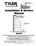
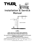
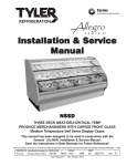
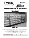
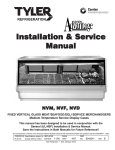
Installation & Service
Manual
LDFL
FRONT LOAD ROLL-IN DAIRY MERCHANDISERS
Medium Temperature Refrigerated Display Cases
This manual has been designed to be used in conjunction with the
General Installation & Service Manual.
Save the Instructions in Both Manuals for Future Reference!!
This merchandiser conforms to the Commercial Refrigeration Manufacturers Association Health and Sanitation standard CRS-S1-96.
PRINTED IN Specifications subject to REPLACES
IN U.S.A.
change without notice. EDITION
5/04
ISSUE
DATE
12/05
Tyler Refrigeration * Niles, Michigan 49120
PART
NO.
9027545
REV.
C
Installation & Service Manual
LDFL
CONTENTS
Page
Specifications
LDFL Specification Sheets . . . . . . . . . . . . . . . . . . . . . . . . . . . . . . . 4
Pre-Installation Responsibilities . . . . . . . . . . . (See General I&S Manual)
Installation Procedures
Carpentry Procedures . . . . . . . . . . . . . . . . . . . . . . . . . . . . . . . . . 6
Leveling the Cases . . . . . . . . . . . . . . . . . . . . . . . . . . . . . . . . . . . . . 6
Joining Cases . . . . . . . . . . . . . . . . . . . . . . . . . . . . . . . . . . . . . . . . 6
Sealing Joints . . . . . . . . . . . . . . . . . . . . . . . . . . . . . . . . . . . . . . . . 6
Special Instructions . . . . . . . . . . . . . . . . . . . . . . . . . . . . . . . . . . . . 6
Refrigeration Procedures . . . . . . . . . . . (See General I&S Manual)
Patch Ends . . . . . . . . . . . . . . . . . . . . . . . . . . . . . . . . . . . . . . . . . . 9
Supporting Cases From the Building . . . . . . . . . . . . . . . . . . . . 10
Joint Trim Filler Kit . . . . . . . . . . . . . . . . . . . . . . . . . . . . . . . . . . . . 13
Patch End Joint Trim Assembly Filler Kit . . . . . . . . . . . . . . . . . . . . 14
Hood Assembly . . . . . . . . . . . . . . . . . . . . . . . . . . . . . . . . . . . . . . 15
Shelving and Shelf Base Installation . . . . . . . . . . . . . . . . . . . . . 16
Installation Procedure Check Lists . . . . (See General I&S Manual)
Wiring Diagrams . . . . . . . . . . . . . . . . . . . . . . . . . . . . . . . . . . . . . . . . . . 16
LDFL Domestic & Export (50Hz) 8’ Case Circuits . . . . . . . . . . . . . 17
LDFL Domestic & Export (50Hz) 12’ Case Circuits . . . . . . . . . . . . 18
Cleaning and Sanitation . . . . . . . . . . . . . . . . . . (See General I&S Manual)
Parts Information
Operational Parts List . . . . . . . . . . . . . . . . . . . . . . . . . . . . . . . . . 19
Cladding and Trim Parts List . . . . . . . . . . . . . . . . . . . . . . . . . . . 20
TYLER Warranty . . . . . . . . . . . . . . . . . . . . . . . (See General I&S Manual)
The following Medium Temperature Front Load Roll-In Dairy Merchandiser models
are covered in this manual:
MODELS
DESCRIPTION
LDFL
8’ & 12’ FRONT LOAD ROLL-IN DAIRY MERCHANDISER
May, 2004
Page 3
LDFL
Tyler Refrigeration
SPECIFICATIONS
LDFL Front Load Roll-In Dairy Merchandiser Specification Sheets
Page 4
May, 2004
Installation & Service Manual
May, 2004
LDFL
Page 5
LDFL
Tyler Refrigeration
INSTALLATION PROCEDURES
Sealing Joints
Carpentry Procedures
Tubes of caulking compound are furnished
in the blister pack. The best time to make a
waterproof case joint is at installation. It is
recommended that two beads of caulking
be used, one inside of the foam gasket for
sanitation and one outside of the foam gasket for refrigeration. For an added measure
of sealing, air-conditioning/heating duct tape
can be used under inside joint trims.
Leveling the Cases
Check the levelness of the floor area to be
used. The floor surface where this case is to
be located should be as smooth and level as
possible. Be sure there are no large bumps
or dips in the floor. Insert shims under the
case where necessary. The highest area of
the line-up will have to be the determining
high level point. The cases can then be
leveled and joined from a level case at the
high point. Level cases are necessary for
both case pull-ups and proper operation.
Small metal shims are furnished in the pull-up
parts kit.
Joining Cases
Pull-up parts are shipped with the case in a
“Blister-pack”. A list of parts furnished and
where they are used is in the pack. Not all
parts may be necessary for a particular case.
Access panels must be removed to install
pull-up hardware.
CAUTION
See “General I&S Manual” for proper
refrigeration line installation and sealing.
Special Instructions
Be sure to read and understand the special
instructions on handling these cases in this
manual. Pay particular attention to the
sections dealing with the anchoring of
these cases to walls and/or roof structures.
WARNING
These cases are top heavy and require
two or more people to move and/or
position them. Improper handling of
these cases could result in personal injury.
1. Remove the items packed on the skid.
Cases must be pushed together as close
as possible before pulling them together
with the pull-up bolt hardware.
Pull-up angles in the cases are factory installed for ease of field installation. Adjacent
foam cases in a line-up may require different
amounts of shimming to bring the cases into
proper alignment.
Joint and end trims are shown elsewhere in
this manual. Follow these instructions to
complete assembly of these cases.
Patch ends are shipped loose because of
shipping height limitations. Patch end kit
drawings are provided in this manual.
2. Carefully raise the case (1) by tilting
forward far enough to get enough
clearance for the rear wall extension (2).
Page 6
May, 2004
Installation & Service Manual
3. Apply the grey pressure sensative gasket
(3) on both sides of the black foam gasket
on the rear wall extension (2).
4. Install the rear wall extension (2) to the
bottom of the case (1) with four bolts (4),
washers (5) and nuts (6).
5. Install drain extension (7) on the bottom
of the case (1) and secure with a hose
clamp (8).
LDFL
6. Move the case against the wall where it
is to be located. Raise the telescoping
extensions (9) and secure the case to the
wall (or specifically designed structure).
7. Remove the rest of the skid.
8. Pilot drill 3/16” holes in rear wall extension
(2) and install the base cladding (10) with
self tapping screws.
9. Install joint trims and pull-ups per joint
trim kit drawing.
10. Install patch ends per the patch end kit
drawing.
May, 2004
Page 7
LDFL
Tyler Refrigeration
NOTE
Since the top panel is the service
access panel for fans and refrigeration
lines, it must be kept clear.
Waste Outlet - Floor Drain
The preferred method is an in floor drain.
Position drain so floor sweepings can not be
swept into the drain.
The alternate method is a flush drain, where
permitted. NOTE: Do not slope floors,
since trucks need a flat platform.
Page 8
IMPORTANT
The information herein is only a general
recommendation since store structures
vary in strength and design. It is
therefore necessary that the installing
contractor and user assure themselves of
the structural integrity of a chosen means
of supporting these cases. TYLER can
assume no liability for the consequences
which may result from failure of structures
or structural connections between this
case and parts of a building.
May, 2004
Installation & Service Manual
LDFL
Patch Ends
A single case is self-supporting with the
ends carrying the weight. Shipping height
limitations make it necessary to ship the
case without ends. They must be installed
on location after the rear wall extension is
added to the case.
One inch structural partitions are available
for use on line-ups.
The one inch structural partition can be used
between every case so that the entire line-up
will be self-supporting. A drawback is that
the partitions limit flexibility.
The recommended method of supporting
cases calls for supporting the cases from
existing or specially constructed structures.
Copy of label attached to each front load air
skreen display case.
IMPORTANT NOTICE
This case was designed to provide a high
degree of display flexibility in shelving and
in roll-in carts. The base structure has
been eliminated, making the merchandiser
dependent upon support from walls and/or
roof members. Single 8’ or 12’ cases can
also be supported from patch ends.
When two or more cases are to be
installed and assembled, the cases must
be attached to structural walls and/or
structural portions of the roof . This
meets the case weight requirement of
150 lb. per lineal foot .
WARNING
If this case is part of a line-up that
requires disassembly, use great care
during disassembly. The case line-up is
not self-supporting and could injure or
cause death if it fell.
May, 2004
Page 9
LDFL
Tyler Refrigeration
Support Cases From The Building
Installing cases in a continuous line-up to
support the cases and to carry all possible
additional shelving loads can be done in
several ways:
1. A case line-up can be set close to a wall
and gain support from it.
IMPORTANT
The information herein is only a general recommendation since store structures vary in strength
and design. It is therefore necessary that the
installing contractor and user assure themselves
of the structural integrity of a chosen means of
supporting these cases. TYLER can assume no
liability for the consequences which may result
from failure of structures or structural connections
between this case and parts of a building.
2. When no building wall is available,
the case may be cable attached to
the roof structure. Truss work might
also be used. There are pre-drilled
holes on the ends of each case so
that 3/8” eyebolts or other bolts (up
to 1/2”) can be used. 1/4” cable
with a minumum 2000 lb. tensile
strength is recommended. The
base must be anchored to the floor
and sway bars as necessary must
be used.
3. Columns may be run from floor
to ceiling with a girder for case
attachment.
4. Overhead structures can be used
to support the cases and/or store
decor from above.
Page 10
May, 2004
Installation & Service Manual
LDFL
Rear column mounted in concrete
Line-up may be supported by various
beam details
Case has
back and top
May, 2004
LDFL suspension system rear
mounted column
Page 11
LDFL
Tyler Refrigeration
Page 12
May, 2004
Installation & Service Manual
LDFL
May, 2004
Page 13
LDFL
Tyler Refrigeration
Page 14
May, 2004
Installation & Service Manual
LDFL
Hood Assembly
WARNING
Make sure all power is off to the case.
Electrical servicing should always be
done by a qualified electrician. Improper
servicing could result in product damage
and/or personal injury.
1. Pull the 3-prong female receptacle (1)
through the hood extension weld
assembly (2).
5. Swing the light channel assembly (5) up
into place and secure with truss head
screws (8).
2. Fasten hood extension weld assembly (2)
to the canopy (3) with tappit screws (4).
6. Install top front cladding (9) over ballast
(10) with screws (11).
3. Hook the light channel assembly (5) into
the front lip of the front hood (6).
7. Complete the assembly by installing the
hood extension joint trim (12) with truss
head screws (13).
4. Plug the light channel wire (7) into the
female receptacle (1).
May, 2004
Page 15
LDFL
Tyler Refrigeration
Shelving and Shelf Base Installation
When 48” shelving is to be used, installation
is as in conventional cases. 24” and 48”
shelf bases can be used, or shelves can be
mounted above roll-in carts. If 24” shelves
are used, it is necessary to attach uprights
at a 24” spacing as shown to the right. The
uprights are symetrical so they can be used
for right or left hand applications just by
reversing them. Pilot drill 3/16” on a line
3 1/4” down from the top. This also coincides with the centerline of the top slot on
the built-in shelving uprights. Attach the
uprights with the provided hex head screws
at top and bottom using the upper hole in
each pair of holes in the upright.
Shelf Bases
Shelf bases are 24” or 48” wide.
Fronts for the shelf bases are 24,
48, 96 or 144” wide. Front ducts
attach to the bases with “Hedlok”
fasteners. These plastic interlocking devices provide easy removal,
yet hold the front ducts securely.
Just pry up to remove. Push in
place to install.
WIRING DIAGRAM
ELECTRICIAN NOTE - OVERCURRENT
PROTECTION
120V circuits should be protected by 15 or 20 Amp devices per the requirements noted on the cabinet nameplate or the National Electrical Code, Canadian Electrical Code - Part 1, Section 28. 208V defrost circuits
employ No. 12 AWG field wire leads for field connections. On remote cases intended for end to end line-ups,
bonding for ground may rely upon the pull-up bolts.
Page 16
May, 2004
LDFL Domestic & Export (50Hz) 8’ Case Circuits
May, 2004
Page 17
LDFL Domestic & Export (50Hz) 12’ Case Circuits
Page 18
May, 2004
Installation & Service Manual
LDFL
PARTS INFORMATION
Operational Parts List
Case Usage
Electrical Circuit
Domestic
115 Volt 60 Hertz
Export
220 Volt 50 Hertz
Case Size
8’
12’
8’
12’
Fan Motor
5243498
9 Watt
5243498
9 Watt
9458942
18.3 Watt
9458942
18.3 Watt
Fan Motor Brackets
5205112
5205112
5205112
5205112
Fan Blades (8.75” 31° 3B)
5104858
5104858
----
----
----
----
5054140
5154140
Fan Bracket Plate
9041077
9041077
9041077
9041077
Opt. ECM Fan Motor
9025000
12 Watt
9025000
12 Watt
----
----
Opt. ECM Fan Motor Brackets 5205112
5205112
----
----
Opt. ECM Fan Blades
(8.75” 30° 5B)
5187551
5187551
----
----
T-8 Lamp Ballast (canopy)
(1st & 2nd row)
5966635
5991030
9322288
9322287
5991029
5991030
9322286
9322287
5204769
5049140
5204859
5204859
5049140
5049140
5989796
5989796
T-8 Lampholder (canopy)
5232279
5232279
5232279
5232279
800MA Lampholder (canopy)
(telescoping)
5614628
5614628
5614628
5614628
5614629
5614629
5614629
5614629
Light Switch (SPST)
5100565
5100565
5100565
5100565
Anti-Sweat Heater
(air grid retainer)
5124818
5124819
5081149
5081150
(8.75” 26° 3B)
(3rd row)
Opt. 800MA Lamp Ballast
(canopy)(1st & 2nd row)
(3rd row)
(stationary)
For information on operational parts not listed above contact the TYLER Service Parts
Department.
December, 2005
Page 19
LDFL
Tyler Refrigeration
Cladding and Trim Parts List
Item Description
LDFL
8’
12’
1309067 (9)
1309067 (12)
9026544
9026546
5183536 (5)
5183536 (5)
1
Screw (per close-off panel assy)
2
Close-off Panel Assembly
3
Screw (per top cover)
4
Top Cover
5186277
5186278
5
Lower Close-off Panel
9026548
9026548
5183536 (2)
5183536 (2)
9026544
9026546
Screw (per close-off panel assy)
1309067 (9)
1309067 (12)
7
Screw (per canopy)
5183536 (4)
5183536 (6)
8
Front Canopy Hood, Painted
9025223
9025224
9
Canopy Hood Backer, Painted
9025983
9025983
10
Screw (per backer)
5205439 (2)
5205439 (2)
11
Standard Hood Joint Trim
5222015
5222015
Short Hood Joint Trim
5222048
5222048
5205439 (6)
5205439 (6)
Screw (per lower close-off)
6
Close-off Panel Assembly
12
Screw (per hood joint trim)
13
Light Channel Joint Trim
5222014
5222014
14
Bumper Retainer
9025504
9025506
15
Color Band, Painted
NA
NA
16
Color Band Backer, Painted
NA
NA
17
Bumper End Trim
---- color by order ----
18
Bumper Backer
---- color by order ----
19
Bumper
---- color by order ----
20
Front Lower Cladding, Painted
NA
NA
21
Rivet (per lower cladding)
5104702 (6)
5104702 (6)
22
Shoulder Screw (per lower cladding)
9025833 (16)
9025833 (24)
23
Base Extension Assembly
5055027
5055028
Foam Base Extension
5054973
5054974
Reinforcement Channel
5055031
5055032
24
Screw (per channel)
1309067 (6)
1309067 (8)
25
Screw (per cart stop joint trim)
5205439 (2)
5205439 (2)
26
Cart Stop Joint Trim
5184553
5184553
27
Cart Stop Assembly
5184559
5184560
28
Screw (per cart stop assembly)
5183536 (6)
5183536 (10)
29
Raceway Cover
5184498
5184499
5111197 (7)
5111197 (9)
5184500
5184501
Screw (per raceway cover)
30
Raceway Assembly
Page 20
May, 2004
Installation & Service Manual
LDFL
Item Description
31 Screw (per raceway assembly)
8’
5183536 (6)
12’
5183536 (8)
32
Screw (raceway cover plate)
5111197 (7)
5111197 (9)
33
Raceway Cover Plate
5184497 (2)
5184497 (2)
34
Nut (per end spacers)
5100634 (2)
5100634 (2)
35
Lock Washer (per end spacers)
5101006 (2)
5101006 (2)
36
Flat Washer (per end spacers)
5100979 (4)
5100979 (4)
37
Machine Screw (per end spacers)
5107443 (2)
5107443 (2)
38
Nut (per end spacers)
5100643 (6)
5100643 (6)
39
Lock Washer (per end spacers)
5628631 (6)
5628631 (6)
40
Flat Washer (per end spacers)
5100982 (12)
5100982 (12)
41
Machine Screw (per end spacers)
5120913 (6)
5120913 (6)
42
Rivet (per end spacers)
5105037 (8)
5105037 (8)
43
End Spacer
5184602 (2)
5184602 (2)
May, 2004
Page 21