1
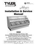
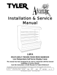
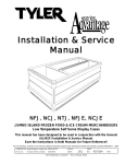
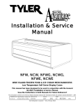
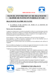
Installation & Service
Manual
L6DLA, L6DMA, L6DHA, L6DLRA, L6DMRA
MULTI-SHELF DAIRY/DELI MERCHANDISER
Medium Temperature Self Serve Display Cases
This manual has been designed to be used in conjunction with the General
Installation & Service Manual.
Save the Instructions in Both Manuals for Future Reference!!
This merchandiser conforms to the Commercial Refrigeration Manufacturers Association Health and Sanitation standard CRS-S1-96.
PRINTED IN Specifications subject to REPLACES
IN U.S.A.
change without notice. EDITION
3/99
ISSUE
DATE
7/99
Tyler Refrigeration Corporation * Niles, Michigan 49120
PART
NO.
9027541
REV.
D
Installation & Service Manual
L6D(L, M, H, LR, MR)A
CONTENTS
Page
Specifications
L6DLA, L6DMA, L6DHA, L6DLRA, L6DMRA Specification Sheets . . 4
Pre-installation Responsibilities . . . . . . . . . . . (See General I&S Manual)
Installation Procedures
Carpentry Procedures . . . . . . . . . . . . . . . . . . . . . . . . . . . . . . . . . 7
Case Pull-Up Locations . . . . . . . . . . . . . . . . . . . . . . . . . . . . . . . . . 7
Joining Rear Load Cases to Coolers . . . . . . . . . . . . . . . . . . . . . . . 7
Electrical Procedures . . . . . . . . . . . . . . . . . . . . . . . . . . . . . . . . . . 8
Plumbing Procedures . . . . . . . . . . . . . . (See General I&S Manual)
Refrigeration Procedures . . . . . . . . . . . (See General I&S Manual)
Defrost Information . . . . . . . . . . . . . . . . . . . . . . . . . . . . . . . . . . . . 8
Defrost Control Chart . . . . . . . . . . . . . . . . . . . . . . . . . . . . . . . . . . . 9
Installation Procedure Check Lists . . . . (See General I&S Manual)
Wiring Diagrams . . . . . . . . . . . . . . . . . . . . . . . . . . . . . . . . . . . . . . . . . . . 8
L6DA Domestic & Export (50Hz) Case Circuits . . . . . . . . . . . . . . . . 9
Optional Electric Defrost Circuit . . . . . . . . . . . . . . . . . . . . . . . . . . 13
Optional Gas Defrost Circuit . . . . . . . . . . . . . . . . . . . . . . . . . . . . . 13
Cleaning and Sanitation . . . . . . . . . . . . . . . . . . (See General I&S Manual)
General Information
Egg Merchandiser Kit . . . . . . . . . . . . . . . . . . . . . . . . . . . . . . . . . 14
Peg Bar Information . . . . . . . . . . . . . . . . . . . . . . . . . . . . . . . . . . . 15
Shelf Air Baffle Information . . . . . . . . . . . . . . . . . . . . . . . . . . . . . 16
Rear Load Baffle Information . . . . . . . . . . . . . . . . . . . . . . . . . . . . 17
Service Instructions
Preventive Maintenance . . . . . . . . . . . . . . (See General I&S Manual)
Ballast and Lighting Locations . . . . . . . . . . . . . . . . . . . . . . . . . . . 17
Defrost Heater Replacement . . . . . . . . . . . . . . . . . . . . . . . . . . . . . 18
Parts Information
Operational Parts List . . . . . . . . . . . . . . . . . . . . . . . . . . . . . . . . . . 19
Cladding and Trim Parts List . . . . . . . . . . . . . . . . . . . . . . . . . . . . . 20
TYLER Warranty . . . . . . . . . . . . . . . . . . . . . . . (See General I&S Manual)
The following Medium Temperature, Multi-Shelf Dairy and Deli Merchandiser models are
covered in this manual:
MODEL
DESCRIPTION
L6DLA
6’, 8’ & 12’ DAIRY/DELI MERCHANDISER WITH 18” FRONT
L6DMA
6’, 8’ & 12’ DAIRY/DELI MERCHANDISER WITH 22” FRONT
L6DHA
6’, 8’ & 12’ DAIRY/DELI MERCHANDISER WITH 26” FRONT
L6DLRA
8’ & 12’ DAIRY/DELI MERCHANDISER WITH 18” FRONT & REAR DOORS
L6DMRA
8’ & 12’ DAIRY/DELI MERCHANDISER WITH 22” FRONT & REAR DOORS
July, 1998
Page 3
L6D(L, M, H, LR, MR)A
Tyler Refrigeration
SPECIFICATIONS
L6D(L, M, H, LR, MR)A Dairy/Deli Merchandiser Specification Sheets
Page 4
March, 1999
Installation & Service Manual
L6D(L, M, H, LR, MR)A
L6D(L, M, H)A Dairy/Deli Merchandiser
September, 1998
Page 5
L6D(L, M, H, LR, MR)A
Tyler Refrigeration
L6D(LR, MR)A Dairy/Deli Merchandiser
Page 6
September, 1998
Installation & Service Manual
L6D(L, M, H, LR, MR)A
INSTALLATION PROCEDURES
Carpentry Procedures
Case Pull-Up Locations
Joining Rear Load Cases to Coolers
(L6DLRA and L6DMRA only)
For U.L. and temperature performance
requirements, L6DLRA and L6DMRA cases
must be backed by a refrigerated area.
TYLER walk-in coolers are available with the
necessary special parts and instructions to
make the installation.
NOTE
Please ensure that the cooler opening is
insulated and sealed completely to the rear
of the display case.
All L6DA models have four pull-ups at each
end of the case. Pull-ups A, B, C and D are
located as shown and should be installed and
tightened starting with A and finishing with D.
See “General I&S Manual” for line-up
assembly instructions.
July, 1998
Page 7
L6D(L, M, H, LR, MR)A
Tyler Refrigeration
Electric
Gas
Electrical Procedures
4
4
36
12-15
50°F
55°F
Most klixons klixons are located on the right
Electrical Considerations
CAUTION
Make sure all electrical connections at
components and terminal blocks are tight.
This will prevent burning of electrical terminals and/or premature component failure.
NOTE
Raceway covers will be shipped loose.
See the “General I&S Manual” for raceway
cover installation and removal instructions.
Case Fan Circuit
This circuit is to be supplied by an uninterrupted, protected 120V circuit. The case fan
circuit is not cycled, except when equipped
for gas defrost. On gas defrost cases the fan
circuit is controlled by a klixon.
NOTE
With gas defrost, the fans will not restart
until the coil temperature reaches the
appropriate temperature.
Fluorescent Lamp Circuit
The standard case lighting system is 800MA
T-12 high output (HO) lamps. The standard
lighting is 1-row of horizontal canopy lights.
Defrost Information
See “General I&S Manual” for operational
descriptions for each type of defrost control.
Defrost Control Chart
Defrost
Type
Off Time
Page 8
Defrost
Defrosts Duration
Per Day
(Min)
4
36
Term.
Temp.
-----
end of the evaporator coil. The diagram
shows the location for each defrost type that
uses a klixon.
NOTE
The Gas Defrost Termination klixon is
located at the by-pass check valve.
CAUTION
If electronic sensors are used in place of
the klixons, the sensors must be located in
the same location as the klixons for that
defrost type. Any other locations will
effect the refrigeration efficiency of the
case.
WIRING DIAGRAMS
ELECTRICIAN NOTE - OVERCURRENT
PROTECTION
120V circuits should be protected by 15 or 20 Amp
devices per the requirements noted on the cabinet
nameplate or the National Electrical Code, Canadian
Electrical Code - Part 1, Section 28. 208V defrost
circuits employ No. 12 AWG field wire leads for field
connections. On remote cases intended for end to
end line-ups, bonding for ground may rely upon the
pull-up bolts.
The following wiring diagrams on pages 9
thru 13 will cover the L6DA case circuits, electric defrost circuit and gas defrost circuit. The
lighting circuit are covered in the case circuit
diagrams.
March, 1999
July, 1998
Page 9
Page 10
July, 1998
July, 1998
Page 11
Page 12
July, 1998
Installation & Service Manual
L6D(L, M, H, LR, MR)A
Optional Electric Defrost Circuit
Optional Gas Defrost Circuit
July, 1998
Page 13
L6D(L, M, H, LR, MR)A
Tyler Refrigeration
GENERAL INFORMATION
Egg Merchandiser Kit Instruction
All egg shelves come galvanized or stainless
steel. The upper egg shelves are 15” x 48”
and come with 82 degree fixed white brackets. The brackets are available in one position only. The upper egg shelves assemblies
include a rear air close-off.
Tilted base egg shelves come in 4’ modules.
They are designed and notched to fit inside
the existing 2’ bottom trays.
Page 14
NOTE
Egg shelves are designed to catch and hold
spilled liquids so they can be cleaned up
before getting further into the case. If the
tilted base shelves are used upside down,
improper shelf support will result causing
the middle of each shelves to sag. Upside
down usage also allows drippage to get into
the case making cleaning very difficult.
Good sanitation is essential for egg merchandising.
July, 1998
Installation & Service Manual
L6D(L, M, H, LR, MR)A
Peg Bar Information
The hang up blister pack has become a standard means of marketing sliced luncheon meats and
other delicacies. It appears that all that is needed to adapt multi-shelf cases for these packages
is to add peg bars and pegs. However, it isn’t quite that simple, because the removal of shelves
changes more than the appearance of the case.
CAUTION
Always use two shelves or baffles in cases using peg bags. This provides and maintains
the protective air flow in the case and proper product cooling and storage.
Figure 1 shows
the air flow in a
Multi-Deck display merchandiser with
shelves. Air
flow from the
top and back
forms a protective barrier to
ambient air. This
is where the
name “Air
Skreen” comes
from.
Figure 2 shows
what happens
to the air flow
when the
shelves are
removed. The
air drifts back to
the rear duct
and swirls
about. This
breaks the “Air
Skreen”, causing the case air
to mix with
ambient air to a
great extent.
Figure 3 depicts what happens to the air flow
in a case full of peg bars. The air falls
through openings between packages and
fails to maintain a protective “Air Skreen”.
When the bars are fully stocked, the effect is
July, 1998
minimized, but
product temperatures will not
be as good as
they could be.
Sweating may
be noticed on
the top duct
above the bars.
The coil will also
frost faster,
requiring more
frequent
defrosts.
Figure 4 shows
the proper air
flow for cases
with peg bars.
The addition of
either a shelf or
a baffle between
tiers of peg bars
maintain proper
air flows and
temperatures in
the case. Two
shelves or baffles or a shelf
and a baffle as
shown will keep
the air flow out
to the front of the cases. The top baffle or shelf
must be about 18” from the top. No baffles are
required when two shelves are used below the
peg bars. Shelves and/or baffles should
extend across the full width of the case.
Page 15
L6D(L, M, H, LR, MR)A
Tyler Refrigeration
Shelf Air Baffle Information
in the peg bar.
Air baffle shelves should always be used with
peg bars for hanging meat displays. Air baffle shelves are non-load bearing and are used
only to help direct the air flow. The baffles
should be installed between two rows of peg
bars, approximately 18” down from the top of
the case interior. Baffles and/or baffle shelves
can be made of plexiglass or sheet metal.
Offset support arms must be installed in the
peg bar so the notches in the air baffle shelf
can fit over them. Install support arms in the
same manner as the pegs (with offset up).
3.
Non-load bearing air baffle shelf runs
the entire length of the case.
1. 48” peg bar with 52 holes to accept pegs.
Air baffle shelf rests on the two offset support
arms. The notches in the shelf must fit over
the support arms.
Flat side of holes in peg bar must be down
and to the front of the bar. Attach two hook
brackets to peg bar with two clamp brackets
and four screws. Position and install peg bar
in slotted holes in back of case.
4. Card moulding is offset 2” in front and
3/4” above the pegs.
2. 15” pegs and offset support arms lock in
place on the peg bar.
After marking the desired locations in the peg
bar, install the pegs into peg bar holes. Hold
peg at 90° angle to peg bar. Insert peg into
hole in peg bar. Rotate peg until angled end
points up. Pull peg out until peg sits properly
Page 16
Slide the card moulding onto the two offset
support arms. The support arm washers
should be positioned on the outside of the
card moulding. Center the card moulding so
it is aligned with the peg bar. Tighten the
wing nuts to secure the card moulding to the
support arms. To remove card moulding as
an assembly; loosen the wing nuts, rotate the
support arms 90°, and remove the entire
assembly.
July, 1998
Installation & Service Manual
Rear Load Baffle Information
NOTE
The air close-off/product stops are
attached to the shelves at the factory.
• 8’ cases use 32 1/2” air close-offs.
• 12’ cases use 32 1/2” RH & LH side air
close-offs and 37 1/4” center air closeoffs.
Shelves are shipped in the proper position. If
shelves are removed, be sure they are
replaced in the proper order. It is necessary
for proper air flow in the case. Omit shelf
shown by dotted line for cases with only three
rows of shelves
March, 1999
L6D(L, M, H, LR, MR)A
SERVICE INSTRUCTIONS
See “General I&S Manual” for T-8 and
800MA T-12 lamp, canopy ballast, fan blade
and motor, and color band and bumper
replacement instructions.
Ballast and Lighting Locations
All light ballasts are located under the canopy
and mounted above or on the top of the
canopy light channel. This includes remote
ballasts for optional shelf lights and optional
nose lights. The canopy light(s) are under the
canopy light channel in the top of the case.
The optional shelf lights are mounted under
the top interior liner above each shelf section.
Page 17
L6D(L, M, H, LR, MR)A
Tyler Refrigeration
Defrost Heater Replacement
WARNING
Always shut off electricity to the entire
case before replacing a defrost heater.
Automatic cycling of fans or electrical
power to wire ends could cause personal
injury and/or death.
2. Disconnect defrost heater plug (3) from
junction block (4).
3. Remove mounting screws and lift up fan
plenum (5).
4. Remove defrost heater (6) from mounting
clips (7) and case (2).
1. Remove bottom trays (1) from case (2).
5. Install new defrost heater (6) in reverse
order.
6. Restore electrical power to case.
Page 18
July, 1998
Installation & Service Manual
L6D(L, M, H, LR, MR)A
PARTS INFORMATION
Operational Parts List
Case Usage
Electrical Circuit
Domestic
Export
115 Volt 60 Hertz
220 Volt 50 Hertz
Case Size
6’
8’
12’
8’
12’
Fan Motors
5243498
9 Watt
5243498
9 Watt
5243498
9 Watt
5223696
18.3 Watt
5223696
18.3 Watt
Fan Motor Brackets
5205112
5205112
5205112
5205112
5205112
Fan Blades (8.75” 35° 5B)
5643563
5643563
5643563
-
-
Fan Blades (8.75” 26° 5B)
-
-
-
5054140
5054140
800MA Ballast (one lamp)
5049140
5049140
5049140
5204859
5204859
800MA Ballast (two lamp)
5049140
5204769
5049140
5204859
5204859
Opt. Ballast (T-8 shelf lamps)
5966635
5966635
5966635
9028439
9028439
Opt. Ballast (5th row shelf lamp) 5991029
5991029
5991030
9028437
9028438
T-8 Shelf Lampholder
5232279
5232279
5232279
5232279
5232279
(telescoping)
5614628
5614628
5614628
5614628
5614628
(stationary)
5614629
5614629
5614629
5614629
5614629
Light Switch
5100565
5100565
5100565
5100565
5100565
Opt. Elec. Defrost Heater
9310403
5124521
5124522
5124521
5124522
Opt. Elec. Defrost Term. Klixon
5125211
5125211
5125211
5125211
5125211
Opt. Gas Defrost Term. Klixon
9023508
9023508
9023508
9023508
9023508
Opt. Gas Fan Delay Klixon
9023503
9023503
9023503
9023503
9023503
800MA Lampholder
For information on operational parts not listed above contact the TYLER Service Parts
April, 2000
Page 19
L6D(L, M, H, LR, MR)A
Tyler Refrigeration
Department.
Cladding and Trim Parts List
Item
Description
6’
8’
12’
1
Screw
5183536 (4)
5183536 (6)
5183536 (8)
2
Screw
5183536 (8)
5183536 (8)
5183536 (8)
3
End Cover
9026103 (2)
9026103 (2)
9026103 (2)
4
Canopy Backer, Ptd. -or-
9025983
9025983
9025983
Canopy Joint Trim
9029422
9029422
9029422
5
Canopy Hood, Painted
9025222
9025223
9025224
6
Front Panel
5636774
5203468
5203469
7
Hand Rail/Bumper Retainer
8
Hand Rail Backer
9
Bumper End Trim
10
Color Band, Painted
9023795
9023798
9023800
11
Color Band Backer, Painted
9040223
9040223
9040223
12
Bumper Backer
--------------- color per order ---------------
13
Bumper
--------------- color per order ---------------
14
Front Cladding, Painted
--------------- color per order --------------9025316
9025316
9025316
--------------- color per order ---------------
L6DLA
9025135
9025136
9025137
L6DMA
9025647
9025648
9025649
L6DHA
9300395
9025650
9025651
15
Raceway Cover
--------------- color per order ---------------
16
Raceway Cover Retainer
9023841 (2)
9023841 (4)
9023841 (6)
17
Screw (per retainer)
5183536 (2)
5183536 (2)
5183536 (2)
18
Screw
5183536 (4)
5183536 (6)
5183536 (8)
19
Raceway Cover End Trim
--------------- color per order ---------------
20
Raceway Cover Backer
--------------- color per order ---------------
21
Kickplate
--------------- color per order ---------------
Kickplate Backer
9041790
9041790
9041790
22
Shoulder Screw
9025833 (6)
9025833 (8)
9025833 (8)
23
Kickplate Support Assy.
9042341 (3)
9042341 (4)
9042341 (4)
24
Screw
5183536 (8)
5183536 (12)
5183536 (16)
25
Raceway Support
9041322 (4)
9041322 (6)
9041322 (8)
26
Raceway
9300242
9300243
9300244
Page 20
July, 1999
Installation & Service Manual
Item
Description
28
Horizontal End Trim
29
Pop Rivet
L6D(L, M, H, LR, MR)A
6’
8’
12’
5211585
5211585
5211585
5105037 (5)
5105037 (10)
5105037 (14)
L6DMA ILLUSTRATED
July, 1999
Page 21