1
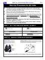
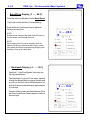
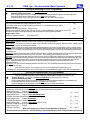
EWS, Inc. / Environmental Water Systems
4.3-1
Care and Use Manual
Metered Softener Series
Information Provided for the Proper Set-Up, Installation and
Start-Up of the following Softeners:
Cabinet “all-in-one” Style:
RT 935
RT 1035
Twin Tank (resin tank with separate brine tank) Style:
TT 1054 TT 1354-11/2
ALL PRODUCT PROUDLY MANUFACTURED AND ASSEMBLED IN THE USA
To the Installer:
Please Read and Leave this Owner’s Manual with the Unit or the Consumer
To the Consumer:
Retain this Care & Use Manual for Product Registration and Future Reference
www.EWSWATER.com
EWS, Inc. / Environmental Water Systems
4.3-2
IMPORTANT GENERAL INFORMATION AND PRE-INSTALLATION CHECKLIST
FOR ALL EWS, INC./ENVIRONMENTAL WATER SYSTEMS
POINT OF ENTRY PRODUCT
Inspect and Verify:
That all components are included with the unit and were not damaged in shipping. If there is obvious
damage to any equipment, it must be noted on the carrier’s Bill of Lading. Open and inspect the contents of all closed crates,
boxes or cartons, and inspect for concealed damage. The manufacturer is not liable for any damage during transit, as stated
and published in the conditions of sale, the receiving packing slip and accepted invoice. The manufacturer has made every
effort to ensure goods should be received in good condition and will support all legitimate claims against any carrier on behalf
of the receiving party. Please see reverse side of all receiving packing slips and yellow labels affixed to boxes for your rights.
Caution:
Do not attempt to install any system using defective or damaged components. Do not install any system
that has been misapplied based assumed water conditions. Do not install any system that has been misapplied based on
usage, line service and/or the conditions and standards of operation stated below.
Warning:
When drilling or cutting, use protective eyewear to prevent possible eye injury due to flying objects. When
using an open flame and/or hot materials, take the necessary precautions for you and the environment to prevent burns,
burning and/or fires.
CONDITIONS AND STANDARDS OF OPERATION
Water Conditions and Issues: Water must be potable and must be micro-biologically correct. Water must be of a known
quality or tested completely and independently to determine its quality, either municipally-treated or non-regulated, individual
or community, well water. Please see in this manual: Qualifications and Applications, Standard Industry Terms and the Limited
Warranty. Information provided for proper specifications are included in our published product manuals, and available through
customer service and on our website. A simple emphasis on, and test for, water hardness is inadequate. Water issues with
iron and/or manganese require their removal by a separate filter unit installed ahead of any other unit.
Water Pressure and Flow Rate: A minimum of 30 PSI (40 PSI for Iron units) and 8 GPM (12 GPM for 1354 Iron units)
is required for a backwash or regeneration valve to operate effectively. Water pressure not to exceed or to surge in excess of
a maximum of 75 PSI for the system. Unsure of pressure or it’s ability to surge? A pressure reducing valve (PRV) becomes an
insurance policy and is highly recommended for this and many other products that limit high pressure in your home. Excessive
pressure will void product warranty.
Water Temperature Range: Feed water temperature not to exceed 110°F or be allowed to go below 40°F. Protect unit
from exceeding high temperatures and never allow unit, its’ drain line and any water to freeze.
Electrical: An uninterrupted alternating current (A/C) supply is required for the operation of the control timer. Please make
sure your voltage supply is compatible with your unit before installation. Low 24 voltage step down transformer 120v, 50/60Hz
Existing Plumbing: Condition of existing plumbing and water heaters should be free from lime and iron buildup. Piping that
is built up heavily and clogged with lime and/or iron should be replaced. Old galvinized or combinations of plumbing materials
and their installation can cause separate water issues and conditions not related to water systems.
Location of Equipment: Units can be installed, almost anywhere. Inside or outside. Valves may be water resistant, not
water proof. Protect any system from the elements. Position equipment upright in its’ designated location, setting on a flat
surface. Level equipment as required. Equipment out of plumb can exhibit poor flow characteristics which will affect the
performance of the system.
Plumbing and Installation: Connect raw water supply to bypass inlet connection. Connect treated water bypass outlet
to home service line. Pipe sizes should be equal to or one size larger than the valve connection (3/4” line with 8 gpm to
standard 1” valving is acceptable). NO Torch, NO Heat - solder all piping as sub-assemblies before installing. Internal valve
damage can result from solder and/or torched heat
By-Pass Valves: All 1” noryl plastic valving are supplied with a 1” high flow dual-port bypass valve and male-threaded yoke
which are required for usage on these systems. On larger brass valves (1”HF, 11/2”, 2” and larger) the installation of a plumbed
bypass with 3 shut-off valves and unions is required, as specified per unit, in this service manual. The need for a proper bypass
is required by warranty and is necessary to isolate the system for maintenance and service.
Drain Connection: Drain line should be sized to handle maximum drain line flow rates for the system as designated on the
control valve. Minimum required drain line size at the valve (1/2” for all 1” valves, 3/4” for all 11/2” valves and larger). Recommended one pipe size larger for runs of 10 feet or more. Avoid overhead pipe runs, as undue backpressure can affect operation
of backwash/regeneration. See backwash (tank filtration systems) and regeneration (softeners) differences, capabilities and
restrictions - in drain connection procedures in those service manuals for those specific units.
ALL SPECIFICS TO EACH SYSTEMS’ SET-UP, INSTALL AND START-UP IS AVAILABLE IN THE SERVICE MANUAL.
WARNING:
IMPROPER INSTALLATION AND/OR APPLICATION WILL
RESULT IN THE VOIDING OF ANY PRODUCT WARRANTY.
All plumbing should be done in accordance with all local plumbing codes.
www.EWSWATER.com
EWS, Inc. / Environmental Water Systems
4.3-3
INSTALLATION SUMMARY - SOFTENERS
Step 1: Locate the following:
Main Water Supply Line, Soft Water Loop or Inlet to Water Heater(s) (depending on application
or restrictions)
Drain Access, Electrical Outlet and Clearances.
Step 2: Check the incoming Water Pressure. Install a pressure regulator (PRV) if the water pressure
exceeds or can surge above 75 PSI.
Step 3: Place the tank where you want to install the unit, making sure the tank is level and on a firm base,
noting the clearances necessary to complete the installation.
Step 3A: TT Units or “Twin Tank” style, place separate brine tank 6” from softener resin tank.
Connect the safety brine assembly found in the brine tank to the 3/8” plastic compression fitting,
then pass the tubing through the hole provided in the brine tank and connect to brass compression fitting on side of valve.
Warning: Do not exceed connecting distance determined by the length of 3/8” OD poly tube provided.
Step 3B: Cabinet Units “all-in-one” style softeners have the brine tank incorporated within the cabinet
along with the resin tank. The connection between the valve and the safety brine assembly has
been factory assembled.
Step 4: Install at barbed connection on brine tank side, min. 5/8” OD tubing (not supplied) to a suitable
drain.
Warning: This is a gravity fed tank drain, in any event that could cause an overflow of the brine tank.
Step 5: Tighten the Valve on the Tank.
Caution: Since handling and moving the unit may loosen the valve head - Hand Tighten the Valve Head in a
Clockwise Direction. Make sure tank cover, if applicable does not interfere or cut into the connection.
Step 6: Identify Water Supply.
Connect raw water supply to bypass inlet connection.
Connect treated water bypass outlet to home service line.
Units: RT935, RT1035 and TT1054 come with dual port bypass valve and male yoke
TT1354-11/2” needs the bypass plumbed by the installer (see additional details)
Warning: Plumb the unit with the bypass and the male yoke included, or for larger brass valves, a bypass
must be plumbed with 3 shut-off valves and unions. Do not cross-connect or plumb backwards.
UNTIL START-UP PROCEDURES - KEEP ALL VALVES TO/FROM SYSTEM CLOSED
Step 7: Connect a backwash drain line (1/2” or 3/4”) based on application and an air gap.
Warning: The performance of softeners are dependent on the proper flow rates for regeneration discharge
FOLLOW START UP PROCEDURES BEFORE
LEAVING THE JOB
www.EWSWATER.com
4.3-4
EWS, Inc. / Environmental Water Systems
Set-Up and Installation for All 1” Valves:
RT 935, RT 1035, TT 1054
top view:
back:
outlet
side:
inlet
side:
to the
home
filtered
supply
from
main
left
right
Yoke
1” MNPT
Dual
Port
Bypass
O-Ring
Connect
Valve
Head
Outlet (filtered) Side:
left side view of valve and drain
port with included drain adaptor,
bypass and male yoke
Must use dual-port, full
flow, noryl bypass with
1” MNPT yoke.
•Shuts off water to/from
the unit
•No additional plumbing
for media replacement or
maintenance
•Less costly plumbing
installation, easier startups, non-corrosive
front:
Inlet (supply) Side:
right side view of valve and
brine line with included
bypass and male yoke
USING THE CONNECTED BYPASS VALVE AND 1” MALE NPT YOKE.
PLUMB INLET (supply) AND OUTLET (filtered) INTO THE UNIT.
•Follow the directional arrows molded onto the valve body and bypass. See pictures below for; top/front/back
and left/right views to prevent plumbing the unit backwards. Teflon tape is the only sealant to used on any of our
fittings. WARNING: No pipe dope.
•NO Heat, No Torch; Leave at least 12” between the male yoke and any solder joints. Failure to do this could
cause interior damage. Consider flexible stainless (1”FNPT x 1”FNPT (3/4” if your application) and at least 18”
in length) connected to copper male adapters, or some other applicable connection - no heat, saves time, neat
install, if applicable/code to your application.
WARNING:
ONCE PLUMBED, DO NOT TURN ON WATER, UNTIL YOU BEGIN START-UP
PROCEDURES.
Set-Up and Installation for 11/2” Valves:
TT 1354-11/2
Materials Needed for Installation:
Back Side:
Union
11/2” pipe length to be
determined
Electric
3 - 11/2” Ball Valves
Outlet (filtered)
2 - 11/2” Unions
Side
See Drain Requirements
Front Side:
11/2” 2850 Valve
Valve Cover: Black
NEMA 1 Rated
for resistence to
dust and moisture.
Union
DO NOT TURN ON WATER,
OPEN ANY VALVES OR
PLUG IN THE ELECTRICAL
UNTIL YOU GO TO THE
START-UP PROCEDURES
Drain:
1” MNPT
Connected (included) to:
Brass Flow Control
Housing with 10 GPM
Flow Restrictor
1” FNPT x 3/4” FNPT
Drain
Bypass
Valve
Hinged: left
Opens: from right
Controls: inside
Inlet (supply) Side
Materials Needed for Drain:
3/4” copper x male adapter
3/4” union
3/4” (min) drain line
length to be determined
PLUMB INLET (supply) AND OUTLET (filtered) INTO UNIT AND PLUMB BYPASS VALVE BETWEEN.
•Follow the directional arrows molded onto the valve body. See picture below for correct set-up.
•Use unions (a quick disconnect feature) at the inlet and outlet pipe, as pictured, to allow future servicing of
system without cutting and replumbing
•Use Ball Valves (preferred - easy to turn on/off) at inlet/outlet pipes and bypass, as pictured for proper installation.
•NO Heat, No Torch; Leave at least 12” between the valve body and any solder joints. Solder joints prior to
connecting to valve body. Failure to do this could cause interior damage. Teflon tape is the only sealant to used
on any of our fittings.
WARNING:
ONCE PLUMBED, DO NOT TURN ON WATER, UNTIL YOU BEGIN START-UP
PROCEDURES.
www.EWSWATER.com
EWS, Inc. / Environmental Water Systems
4.3-5
Start-Up Procedure for All Units
The tank unit(s) have now been plumbed in with the inlet, outlet and drain
connections made in accordance with the manufacturer’s recommendations
and meets applicable plumbing codes.
Now, it is time to fill it with water, plug the unit in, and properly start it up by
following the start-up procedures below.
These units are similar to water heaters and other point of entry product. They
must be plumbed correctly and filled slowly while relieving pressure. These
units are also similar to other sink filtration product. They must be flushed
before beginning usage.
Making the connections, turning on the water and walking away is an
improper installation. Period.
Failure to start up unit properly may cause service issues, unhappy
consumers, and will void the warranty.
STEP 1: FILL THE TANK WITH WATER - SLOWLY!
Units:
RT935, RT1035, TT1054
Units:
TT1354-11/2
See Left Column
See Right Column
You Must Use:
Bypass and Male-Threaded Yoke Included
You Must Plumb:
Inlet/Outlet and Bypass per Schematic
STEP 1-A: PARTIALLY OPEN INLET SIDE ONLY
Following a slow fill procedure will make the backwash and flushing steps easier and more effective.
PARTIALLY OPEN - 1/4 TURN (as
illustrated) on inlet supply side only
to fill tank slowly. Keep outlet side
closed
PARTIALLY OPEN -1/4 TURN with (preferred) Ball Valve or Slowly
and Partially Open Gate Valve on inlet supply side only to fill tank
slowly. Keep outlet side and bypass valves closed.
Inlet
Side:
Open 1/4
turn only
to slowly
fill
Inlet Side Partially Open
Once the tank has been slowly filled, go to the next page. Follow the remaining simple procedures.
www.EWSWATER.com
4.3-6
EWS, Inc. / Environmental Water Systems
STEP 1-B: TANK IS FILLED, OPEN INLET COMPLETELY
SLOWLY OPEN - (as illustrated)
on inlet supply side only.
Keep outlet side closed.
SLOWLY OPEN -Completely open (preferred) Ball Valve or Gate
Valve on inlet supply side only.
Keep outlet side and bypass valves closed.
Inlet
Side:
Open
Position
once filled
Inlet Side Open
Tank is completely filled when sound of water stops or
at a slow pace of 1-2 GPM it will take 5-10 minutes. Keep outlet side closed until later.
STEP 2: PLUG IN THE ELECTRICAL
Plug the 24 volt transformer into any unswitched electrical outlet or an acceptable extension to that outlet. Be sure that if
plugged into a GFI outlet that the outlet has been reset. Please inform the consumer of the need for an unswitched outlet
which can not be turned off and that GFI outlets need to be occassionally checked for operation. Please follow all applicable
local codes. If using an extension, make sure of a complete and secure connection. No spliced connections. Do not break
into wires with fasteners or staples. Make sure transformer has a snug and secure connection to outlet (larger units must use
set screws to secure transformer to outlet). Electrical is used to bring power to the digital valve, in order to keep the time and
operate the automatic backwash program. Cost of this operation is similar to the cost of a radio alarm clock.
STEP 3:
BEGIN THE REGENERATION CYCLE STEPS AS
FOLLOWS FOR START-UP
THESE STEPS ARE CRITICAL FOR THESE
HIGHLY EFFICIENT METERED VALVES
PLEASE FOLLOW THE STEP BY STEP
INSTRUCTIONS
Address Advancement Note:
Push and Hold Extra Cycle Button for approximately 5 seconds to advance the valve into Regeneration
Cycles. As each Regeneration Cycle is Entered a Red Dot will Illuminate on the left of the Regeneration
Cycle Title printed on the face panel.
To advance to the next Regeneration Cycle before it times out, Push the Extra Cycle Button once (Do Not
Hold) once the Number on the left of the Address Display stops flashing.
www.EWSWATER.com
EWS, Inc. / Environmental Water Systems
Begin the Regeneration Cycle Steps
as follows for Start-Up
·
Push and Hold Extra Cycle Button for approximately 5 seconds to advance the valve into regeneration and to the Tank Fill Address.
•
Tank Fill Display [ 1 - - - - 5.0 ]
Allow the Tank Fill to complete the Cycle and Confirm the water is being delivered into the Empty Brine
Tank. Allow the valve to advance to the next cycle without assistance.
1 - - - - 5.0
NOTE: While waiting for the Cycle to complete check
for leaks at Plumbing connections and Factory connections which have been loosened during Shipping
and Handling.
·
Brine Making Display [ 2 - - - 15.0 ]
Once the valve has Advanced into the Brine Making
Cycle wait until the number (2) stops flashing.
Push the Extra Cycle Button Once to advance Valve
to the next cycle.
2 - - - 15.0
www.EWSWATER.com
4.3-7
4.3-8
·
EWS, Inc. / Environmental Water Systems
Brine/Rinse Display [ 3 - - - 60.0 ]
Once the valve has Advance into the Brine/Rinse
Cycle wait until the number (3) stops flashing.
Push the Extra Cycle Button Once to advance
Valve to the next cycle.
NOTE:
A slight sound change of the water flow will occur as
the flow slows down through the valve.
3 - - - 60.0
NOTE:
While waiting for the Cycle to complete check for
leaks at Plumbing connections and Factory connections which have been loosened during Shipping and
Handling. Clean up the Work Area.
·
Backwash Display [ 4 - - - 10.0 ]
Open the 1” High Flow Bypass Valve inlet into
the fully open position.
The Backwash Cycle will Flow water Upward
through the Mineral Bed to purge air bubbles and
any color to the Drain. Allow the Backwash to run
until the Drain runs clean and clear, approximately
0-5 minutes.
Once the Drain is clean and clear Advance Push
the Extra Cycle Button Once to advance Valve to
the next cycle.
www.EWSWATER.com
4 - - - 10.0
EWS, Inc. / Environmental Water Systems
·
4.3-9
Fast Rinse Display [5- - - 10.0 ]
This is a hidden cycle - NO red dot will appear
Once the valve has Advanced into the Fast/Rinse
Cycle wait until the number (5) stops flashing.
Push the Extra Cycle Button Once to advance
Valve to the Service mode.
5 - - - 10.0
Service Mode designated by Alternating flashing
Time of Day and Gallons Remaining
Repeat the Regeneration Cycle steps once Again as follows
• Tank Fill Display [ 1 - - - - 5.0 ]
Once the valve has Advanced into the Tank Tank Fill Cycle wait until the number (1) stops flashing. Push
the Extra Cycle Button Once to advance Valve to the next cycle.
• Brine Making Display [ 2 - - - 15.0 ]
Once the valve has Advance into the Brine Making Cycle wait until the number (2) stops flashing. Push
the Extra Cycle Button Once to advance Valve to the next cycle.
• Brine Rinse Display [ 3 - - - 60.0 ]
Once the valve has Advanced into the Brine Rinse Cycle Confirm the water is being Drawn out of the
Brine Tank. Allow the water to be drawn out of the tank until the air check activates, approximately 2-10
minutes. The Brine Tank will Not completely empty the water below the Air Check Level.
Push the Extra Cycle Button Once to advance the Valve to the next cycle.
• Backwash Display [ 4 - - - 10.0 ]
The Backwash Cycle will Flow water Upward through the Mineral Bed to purge air bubbles and any color to
the Drain. Allow the Backwash to run until the Drain runs clean and clear, approximately 0-5 minutes.
Once the Drain is clean and clear Advance Push the Extra Cycle Button Once to advance Valve to the next
cycle.
• Fast rinse (hidden cycle) Display [5- - - 10.0 ]
Once the valve has Advance into the Fast Rinse Cycle wait until the number (5) stops flashing. Push the
Extra Cycle Button Once to advance Valve to the Service mode.
www.EWSWATER.com
4.3-10
EWS, Inc. / Environmental Water Systems
STEP 4: THE “HOME STRETCH”
1: Once the regeneration cycles steps have been completed the;
Service Mode will be entered.
You will see alternating flashing Time of Day and Gallons Remaining
2: Now and only now is it time to add clean Softener Salt into the Brine Tank,
Maximum: RT Units - 200 lbs; TT Units - 300 lbs.
Recommended: Rock Salt
3: Slowly Open the 1” High Flow Bypass Valve outlet to the Service line or the 11/2” Outgoing
Valve outlet to the Service line (if applicable, keep plumbed bypass valve closed).
See Diagram Below.
4: Set the current Time of day using the Up and Down Arrows to adjust as needed. Please note for
afternoon time settings the PM designation in small letters in the Middle of the Display
window’s top edge should be illuminated.
5: Confirm the Level #1 Programming Address Displays with the Level #1 Factory Address Setting Chart as shown on next page.
STEP 5: FINAL SERVICE POSITION
SLOWLY OPEN the outlet side
the bypass valve so water will
flow to the house. The system
is now ready for service
Outlet
Side:
SLOWLY OPEN the outlet side to the plumbed installation so water will
flow to the house. Keep the bypass valve closed.The system is now ready
for service
Outlet Side Open
Inlet
Side:
Bypass
Closed
Open
Service
Position
Open
Service
Position
Inlet Side Open
A)
Inlet and Outlet Valves are Open. Ready for Service.
B)
The display has returned to the “Time of Day” and “Service” mode and is ready to operate automatically.
If electricity fails, the electronic controller will keep in memory the pre-set program. Use “Up and Down” buttons to
reset thecorrect time of day.
www.EWSWATER.com
EWS, Inc. / Environmental Water Systems
4.3-11
FACTORY PRESET PROGRAMMED PARAMETERS
Regeneration Time of Day
2:00 am
#1 Tank Fill Variable time to fill only as much water as needed,
as determined by the metered valve
#2 Brine Making
15 minutes
#3 Brine Draw /Slow Rinse
60 minutes
#4 Backwash
10 minutes
#5 Fast Rinse (hidden cycle)
10 minutes
#6 Step
OFF
EWS Digital 1” Metered LEVEL #1 Factory Settings
Tank Size
Resin cu. ft.
Water Hardness
9 x 35
0.75
25
10 x 35
1.0
25
10 x 54
1.5
25
13 x 54
2.5
25
Capacity in Grains - minimum setting using only 4lbs of salt per cubic foot of resin****
12,000
16,000
24,000
40,000
Bigger is not better. Grain capacity is not a measure of softener efficiency and operation
****Capacity in Grains of Hardness is a function of the EWS Environmental setting of only 4 lbs of
salt per cubic foot of resin - to reset this line item other addresses must be changed in the # 2
programming to allow system to work properly for another setting. If neede, please contact EWS,
Inc. corporate offices.
Note: this environmental efficiency setting of 4 lbs of salt per cubic foot of resin meets or exceeds the
strictest efficiency standards in the industry and meets or exceeds California SB1006 Compliance.
The idea of throwing more salt at the resin to increase the grains capacity, in order to soften your
water, is an old industry and salesman mentality, in order to sell product. Our softeners can be adjusted up to 60,000 grains or more.
Our level of efficiency allows our EWS softeners to operate better and more efficient, uses less salts,
uses less water and produces less brine discharge.
www.EWSWATER.com
4.3-12
EWS, Inc. / Environmental Water Systems
Setting or Resetting Level #1 Programming
To Enter Program - Push and Hold Program Button For Approximately 5 Seconds
Address Advancement Note:
1.
Push Program Button Once Per Display to advance to until next Address appears. As each Address is
accessed a Red Dot will Illuminate next to it’s Title on the face panel.
2.
Address settings may be changed by pushing either the Up or Down Arrow Button.
DISPLAY/ADDRESS DESCRIPTION
WINDOW DISPLAY
Water Hardness
Set In your local Grains per Gallon (example 25 grains)
[
25 ]
If a number reads “ppm” or “mg/l” divide that number by 17.1 to calculate grains per gallon
System Capacity
Example: 24,000 Grain Capacity - Set by Factory
[
24 ]
Example calculated by 4 lbs salt per cubic foot of resin, California SB1006 Compliance for the 10 x 54
Do Not reset without resetting salt setting and salt dosage for proper system operation
Regeneration Time
[ 2:00 ]
Example: standard 2:00 am
pm indicator OFF
Regeneration Sequence Steps and Purpose
Brine Tank Fill - Brine tank is refilled with a calculated amount of water, determined by the water use from the previous
regeneration, to dissolve exactly the salt amount required for current regeneration.
Brine Making – The system is pausing to allow for full saturation of the brine solution. During the brine making cycle
service water continues to be delivered softened.
Brine In - Brine is ejected from the brine tank and passes through the resin bed in an upward flow, thus removing calcium
and magnesium that has accumulated on the resin and is flushed to drain. As the beads swell during the full brine cycle
the debris (i.e. iron) which may be attached to the beads will be released and be removed more readily during the following
backwash cycle.
Slow Rinse - After the brine has been introduced, brine air check is closed, allowing water to flow through the ejector at a
slow rate, displacing the brine remaining in the resin bed. This insures good utilization of the brine.
Backwash - Flow through the resin bed is reverse of the service flow. Water flows upward at a controlled rate expanding
and agitating the resin and fluidizing the bed. This action loosens sediment and iron that may have collected on the resin
during service and is flushed to drain. Resin fines which developed during service due to oxidation are also removed.
Note: Applications with chlorine levels above 0.5 ppm should have protective removal systems before the
water softener unit
Fast Rinse - The resin is now flushed downward at a set flow rate. This reclassifies the bed and rinses out any remaining
brine left in the resin bed.
After fast rinse step the unit is ready for service, thus completing the regeneration cycle.
While the unit is in regeneration (but not recommended) service is available through the valve with untreated water.
FACTORY SET REGENERATION CYCLE PROGRAMMING
Refer to the information for Factory Preset Programmed Parameters which apply to the system size.
Change as needed to adjust for water conditions, problem water situations, or consumer use.
To Enter Program - Push and Hold Extra Cycle Button For Approximately 5 Seconds
Address Advancement Note:
1.
Push Program Button Once Per Display to advance to until next Address appears. As each Address is
accessed a Red Dot will Illuminate next to it’s Title on the face panel.
2.
Address settings may be changed by pushing either the Up or Down Arrow Button
DISPLAY/ADDRESS DESCRIPTION
WINDOW DISPLAY
Regeneration Cycle
Step #1 - Tank Fill
[1 - - - - XX ]
Variable time to fill only as much water as needed, as determined by the metered valve
Regeneration Cycle
Step #2 - Brine Making
Example: (Brine Making 15 Minutes)
[ 2 - - - 15.0 ]
Regeneration Cycle
Step #3 - Brine Draw/Slow Rinse
Example: (Brine Draw/Slow Rinse for 60 Minutes)
[ 3 - - - 60.0 ]
Regeneration Cycle
Step #4 - Backwash
Example: (Backwash for 10 Minutes)
[ 4 - - - - 10 ]
Regeneration Cycle
Step #5 - Rapid Rinse (hidden cycle)
Example: (Rapid Rinse for 10 Minutes)
[ 5 - - - - 10 ]
Regeneration Cycle
Step #6
Example: Cancelled
[ 6 - - - OFF ]
When all Programming Is Exited. Normal Operation is Resumed.
Arrow must indicate “In Service” and LED Display is alternately displaying Time of Day and Gallons Remaining.
www.EWSWATER.com
EWS, Inc. / Environmental Water Systems
4.3-13
Softener Troubleshooting
PROBLEM
CAUSE
Loss of Resin
A. Broken distribution tube
and/or upper screen
B. Inlet/Outlet Connection Reversed
CORRECTION
A. Replace distribution tube or upper screen
Softener fails to
regenerate
A. Electrical service to unit has been
interrupted
B. Timer motor is defective
C. Control board is defective
C. Power failure
D. Meter not metering
A. Assure permanent electrical service
(Check fuse, plug, pull chain, or switch)
B. Replace timer motor
C. Replace circuit board
C. Reset time of day.Replace backup battery
D.Clean foreign matter out of meter
Hard Water
A. Bypass valve is open
B. No salt in brine tank
J. Flow meter is not measuring correct
K. Meter is not metering
A. Close bypass valve
B. Add salt to brine tank and maintain salt
level above water level
C. Clean injector screen
D. Check brine tank fill time and clean brine
line flow control if plugged.
E. Repeated flushing of the hot water tank is
required
F. Make sure distributor tube is not cracked
Check “O” Ring and tube pilot
G. Replace seals and spacers and/or piston
H. Confirm water chemistry and valve
settings
I. Check previous days usage and/or test hot
water and cold water for hardness
J. Confirm pulse setting in Valve program
K. Clean foreign matter out of meter
Unit used too
much salt
A. Improper salt setting
B. Excessive water in brine tank
C. Power interuption during tank fill
A. Check salt usage and salt setting
B. See Problem No. 8
C. Replace backup battery
Loss of
water pressure
A. Iron buildup in line to water
conditioner
B. Iron buildup in water conditioner
A. Clean line to water conditioner
B. Reconnect inlet/outlet connection properly
C. Injector screen plugged
D. Insufficient water flowing into
brine tank
E. Hot water tank hardness
F. Leak at distributor tube.
G. Internal valve leaking
H. Water chemistry changed
I. Abnormal or high water usage
B. Clean control and add mineral cleaner to
mineral bed. Increase frequency of
regeneration.
C. Remove piston and clean control
C. Inlet of control plugged due to
foreign material broken loose
from pipes by recent work done
on plumbing system.
Loss of mineral
through drain line
Hard water (unit not using salt; liquid
level in brine tank not too high)
A. Upper screen breached or broken
A. Electrical service to unit
interrupted
B. Timer not working
C. Timer improperly set
D. Safety brine valve not
opening
E. Salt "bridged" in brine tank
F. Control valve not refilling brine
tank in brine refill cycle
A. Assure permanent electrical service (check fuse, plug, pull
chain or switch)
B. Replace timer motor
C. Increase frequency of regeneration and/or salt setting
D. Replace safety brine valve
E. Breakup salt
F. Add shim between backplate and valve body
Hard water (unit using salt; liquid
level in brine tank NOT too high)
A.
B.
C.
D.
A. Close bypass (replace if necessary)
B. Increase frequency of regeneration
C. Add salt; maintain above water level
D. Increase frequency of regeneration and/or salt setting (see
HOW TO SET TIMER)
E. Reinstall unit
F. Replace with larger unit
Bypass open
Timer improperly set
No salt in brine tank
Excessive water usage
E. Unit installed backwards
F. Unit undersized
Liquid level in brine tank TOO high
System regenerates at
wrong time-of- day
A.Replace upper screen on Valve
A. Brine valve not closing
B. Salt setting too high
C. Injector screen plugged
D. Drain line frozen, plugged or
restricted
E. Salt "mushed" or sand from
salt plugging bottom of brine tank
F. Incorrect brine line flow
control (BLFC)
A.
B.
C.
D.
Replace brine valve
Reset timer
Clean injector and screen
Free drain
A. Power outage occurred
A. Reset timer
E. Clean out brine tank (see instructions)
F. Replace with correct flow control (see specifications)
CONTINUED NEXT PAGE
www.EWSWATER.com
4.3-14
EWS, Inc. / Environmental Water Systems
Softener Troubleshooting
PROBLEM
Water continuously flows to
drain
CAUSE
B.
C.
or
D.
Water tastes salty.
White spots on glassware and dark
surfaces
CORRECTION
A. Foreign material in control
valve
Internal control leak
Control valve jammed in brine
backwash position
Defective micro-switch
A. Salt setting too high
B. Cyclone distributor tube too
short
A. Sodium residual resulting
from water having very high
hardness or total dissolved
solids (TDS)
Low water pressure (low flow rate)
"Rotten egg" smell (from hot water
ONLY)
"Rotten egg" smell (from both hot and
cold water)
Loss of resin through drain line
A. Iron build-up in line to water
conditioner
B. Iron build-up in water
conditioner
C. Well pumping sand
D. Pump losing capacity
A. Magnesium rod in water
heater
A. Hydrogen sulfide (sulfur) in
water supply
B. Bacterial iron in water supply
C. Algae in water supply
A. Remove piston assembly and inspect bore: remove foreign
material and check control in various regeneration positions
B. Replace seals and/or piston assembly
C. Replace piston, seals and spacers
D. Replace micro-switch
A. Reset program cycle
B. Replace
A. Installation of additional water treatment equipment such as
reverse osmosis or demineralization
A. Clean line to water conditioner
B. Clean control and add Iron-X Mineral Cleaner to resin bed;
increase frequency of regeneration
C. Install sand trap
D. Contact pump repair service
A. Replace with aluminum rod or remove
A. Contact factory for treatment recommendations
B. Install Iron Removal System
C. Pour approximately 1/2 cup laundry bleach into brine well
just before regeneration as frequently as necessary
A. Assure that well system has proper air eliminator control;
check for dry well condition
A. Air in water system
SECTION REPLENISHMENT OF SALT SUPPLY:
The salt storage capacity of the brine tank is approximately 300 lbs. (136 kg.) (125 lbs. for compact). During each regeneration a specific amount
of salt is consumed, thus requiring its periodic replenishment (the frequency is dependent on the regeneration schedule). Always replenish salt
before the supply is exhausted to assure a continuous supply of softened water.
TYPE OF SALT TO USE:
Any type of water softener salt may be used. There are advantages and disadvantages to every type of salt. Please ask your local dealer for his
advice. ROCK SALT IS RECOMMENDED.
BRINE TANK CLEAN-OUT:
To prevent service problems, the brine tank should be emptied and flushed out with a garden hose when dirt and other insolubles accumulate. The
clean-out frequency depends on the type salt used and regeneration frequency. The clean-out should be done when the salt level is low. Steps
to follow:
1) Disconnect brine line at either end.
2) Turn brine tank upside down and discard old salt.
3) Rinse out with a garden hose.
4) Reconnect brine line.
5) Follow start up procedures before adding new salt.
Perform approximately once a year if rock salt is used; with other types of salt, approximately once every other year.
PREVENTING IRON-FOULING OF MINERAL BED:
If iron is present in the water supply, the softener mineral bed will eventually become iron-fouled, resulting in reduced softening capacity and ruststained fixtures. Purchase an EWS Pyrolox Unit for permanent solution.
PERIODICALLY CHECK TIME OF DAY SETTING:
Power outages will cause TIME OF DAY timer setting to become incorrect. To reset, to appropriate HOW TO SET TIME
CLOCK (or METER) REGENERATION CONTROL, Section 3.
CHANGE OF OPERATING CONDITIONS:
Should your family size, your water usage habits, or your water quality change, the regeneration program settings may
have to be adjusted. Consult your dealer if any of the above occur.
PROPER DRAIN AND
AIR GAP
CONFIGURATIONS
www.EWSWATER.com
EWS, Inc. / Environmental Water Systems
4.3-15
EWS Softener Systems Feature:
Full 1” Internal Valve Porting:
1 ¼” Service line connections for use up to 16” diameter tanks (4 cubic feet)
21 GPM Continuous Flow
27 GPM Peak Flow
17 GPM Backwash Flow
CV – 5.4
(industry comparison CV 3.00-5.0)
Up Flow Regeneration – Counter current regeneration decreases the salt usage by 20-40% per regeneration and increases the salt efficiency without hardness slippage.
All EWS Softeners are California SB1006 Efficiency Compliant:
Salt efficiency EWS softeners are set at
4,000K grain/lb. salt or 4 lbs. salt/cubic foot = 16,000 grains per cubic foot capacity
Industry Standard sets up softeners
•
2,667 grain/lb salt or 9lbs. salt/cubic foot = 24,000 grain capacity or for those who need to sell a
bigger is better they reset the salt dosage to 2,133 grain/lb salt or 15 lbs. salt/cubic foot to get 32,000
grains of capacity.
•
EWS gets more out of 16,000 grain capacities then those setting their softeners for the sale and
not the performance. Note the inefficiency of the higher settings and how much more salt it takes to get
to those higher capacity numbers. EWS will save minimum 55% on salt and the related waste water and
brine while providing constant soft water without slippage and other problems associated with softener
use.
“TRUE” Variable Brining – Highest water and salt efficiency
The system calculates the amount of brine to make in order to regenerate only the amount of
softener resin saturated by water hardness during service since the last system regeneration.
Digital “Smart” Metered Usage
•
Regenerates to actual usage and not to estimated usage
•
The meter monitors the water using 133 pulse per gallon of flow (industry standard is 8-20 pulses
per gallon) providing high level accuracy in measuring softened water usage, brine requirements
and reserve capacity adjustments.
•
The sensitivity of the meter can also be used to display small flow rates (in 0.1 of gpm flow)
representing potential leaking plumbing fixtures in the household wasting treated water.
NOVRAM Electronics
NOVRAM electronics, the same as in personal computers, have a self-charging Nicad battery to maintain memory of permanent programming history data in the event of power interruptions.
•
Protected for EFI Interference allowing continual monitoring accuracy
•
Solid state electronics provide maximum reliability for long term trouble free service.
•
Solid state electronics allow easy to set application parameters and are completely field adjust
able to match changed water conditions or problem water situations
•
Easy to read LED display, no need for flashlight to see the display in dark locations
•
Easy programming for adaptation to a wide range of performance parameters on various water
supplies for reliable function and service
•
Digital control has fewer moving parts resulting in less problems and low maintenance
•
Factory programmed for immediate field installation and use
www.EWSWATER.com
4.3-16
EWS, Inc. / Environmental Water Systems
Battery Backup
The valve has a 9-volt battery back up to maintain the time of day, the flow rate, and the
system current data input during power interruptions.
24V Operation
Simplifies installations, maintenance and reduces electrical hazards
UL rated and approved transformer
Soft Water Service During Brine Making
•
The brine making is a full contact time cycle immediately before regeneration needed, insuring
the correct amount of fresh saturated brine solution for a complete regeneration.
•
During the brine making cycle service water continues to be delivered softened.
Brine Before Backwashing
•
Full brining before backwash cycle increases regeneration efficiency because the resin bed is not
mixed with exhausted and active beads but remains properly separated in layers during the brine
cycle. As the beads swell during the full brine cycle the debris (i.e. iron) which may be attached to
the beads will be released and be removed more readily during the following backwash cycle.
•
Brine make up before the system regenerates helps eliminate salt bridging and tank sweating
Soft Water Brine Fill
The ONLY Single Valve on the Market with Soft Water Brine Tank Fill
•
Increases the brining efficiency in using softened water to fill the brine tank. During regeneration
of the resin bed the brine cycle only introduces brine and not hard water elements which take up
resin exchange sites limiting the service capacity of the system.
•
Decreases the potential for debris to be introduced into the brine tank which can create mainte
nance problems with the safety float valve operation, injector screen clogging, brine valve set
wear, injector seating properly and/or clog brine flow control.
Pressure Regulated Injector
•
Pressure regulation for consistent brining with varying water pressure applications maintaining
the accuracy and efficiency of the system capacity
•
Pressure regulated Brining controls the flow and relative feedwater pressure to prevent fluidizing
of the resin bed and preserve the effective salt efficiency from the variable Upflow brining system
HIDDEN 5th CYCLE
•
Hidden 5th Cycle of Fast Rinse eliminates hard water carry over and salt slug contamination to
the down stream service side of the system
•
The 5th cycle is a down flow fast rinse cycle which removes the hard water pocket from the
service flow which disrupts soft water delivery. Hard water in hot water heater takes 2-5 days to
purge
•
This cycle also compacts resin beads for efficient softener operation only found in our upflow
valves.
www.EWSWATER.com
EWS, Inc. / Environmental Water Systems
4.3-17
Self Adjusting Reserve Capacity
•
Beginning reserve capacity is always 33% of total system bed maximum capability
•
The system recalculates the reserve capacity Daily (2:00 AM) based upon the consumers water
usage during the previous days and will adjust the reserve up or down 10% from the previous reserve setting
with a maximum reserve capacity of 50% of bed volume. This allows the system to change automatically to
meet your changing water conditioning requirements without program entries.
Calendar Day Override/Vacation Mode
•
The calendar day override with true variable brining assists in maintaining the bed during periods
of time of inactivity (i.e. vacations) without excessive salt and water usage.
•
Day override keeps bed fresh during inactive or low use periods by regenerating the calculated
bed volume used at preset day intervals.
Extra Cycle Button
Extra cycle button can be activated to regenerate the calculated bed volume that has been used immediately or delayed to 2:00 am the same night.
Upper And Lower Screens
The system is complete with upper and lower screens to protect the valve internals and plumbing fixtures
down line from media and/or debris.Lower distributor system with screen provides maximum use of resin
bed capacity with service flows
Mineral Resin Tank
The mineral tank has injected molded inlet for leak free seals, NSF approved inner lining for sanitation and
fiberglass wrapped exterior for strength – No metal or rust to corrode
Exterior Jacket (optional)
Makes for an attractive appliance and reduces exterior tank sweating in high humidity areas
High Capacity Resin
Delivers high effeciency salt and water usage, longer bed life and lower maintenance
Brine Tank is a high density Polyetheylene . It withstands impacts and retains its shape when full of salt
Dual Safety Brine Valve with over flow port eliminates potential overfilling and spilling onto the floor –
Note: The construction of the safety brine valve does not have solvents
High Flow 1” Bypass Valve with 1” mnpt Yoke
Has independent influent and effluent controls for clean start up and field diagnostic evaluations
Displayed Monitored System Values for easy-to-use trouble shooting and diagnostic evaluations
Time of Day
Capacity Remaining to Next Regeneration
Gallons Used Since Last Regeneration
Average Gallons Used
Flow Rate
Previous Days Usage
Days Since Last Regeneration
www.EWSWATER.com
4.3-18
EWS, Inc. / Environmental Water Systems
The complete EWS, Inc./Environmental Water System
product line from sink to whole-home, available through:
Available on the Internet through Authorized Retail Web Distributors and Business-to-Business ECommerce Distributors.
Available through Authorized Building Wholesale Supply Locations, Kitchen & Bath Showrooms
and Appliance Dealers, and their Building and Plumbing Contractors throughout the United States.
EWS, INC.
Environmental Water Systems
A Complete Line of Water Filtration Product from Sink to Whole-Home
9101 W. Sahara Avenue #105-J8
Las Vegas, Nevada 89117
Telephone: 702-256-8182 Fax: 702-256-3744
E-Mail: [email protected]
Visit us on the web at: www.EWSWATER.com
This service guide and all materials herein is the property and copyright of EWS, Inc. 05/03: 060703
Providing information to help consumers.
All Product Proudly Manufactured and Assembled in the USA
www.EWSWATER.com