1
FILE NO. SVM-05019
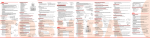
3. WIRING DIAGRAM
3-1. Indoor Unit (For 10k & 13k)
COLOR INDICATION
BROWN
RED
WHITE
YELLOW
BLUE
BLACK
GRAY
PINK
ORANGE
GREEN & YELLOW
GREEN
TERMINAL
BLOCK
BLK
F01
T3.15A
250VAC
1
2
3
4
5
6
7
8
9
R04
CN07
(W HI)
11
22
33
44
55
+12 VDC
3
+5 VDC
Fan Motor
Drive circuit
CN13
(W HI)
1
2
3
4
5
6
7
8
9
1
2
3
4
5
6
7
8
9
W HI
YEL
YEL
YEL
YEL
11
22
33
44
55
LOUVER MOTOR
CN11
123
123
MAIN P.C. BOARD
WP-004
MCC-861
1
5
Power
supply circuit
FUSE
11
22
BLU
BLU
BLU
BLU
BLU
BLU
BLU
BLU
BLU
BLU
10 10
10 10
WHI
11 11
11 11
1
2
3
4
5
6
7
8
9
LINE
FILTER
CN10
YEL
GRY
BRW
INFRARED RAYS
RECEIVING AND
INDICATING PARTS
CN25
(W HI)
CN21
11
22
5
5
3
3
1
1
6
RED
THERMO SENSOR
(TA)
RED
CN24 CN23
CN01
(BLU)
HEAT EXCHANGER
SENSOR
CN03
(W HI)
(TC)
BLK
BLK
W HI
BLK
BLK
BLK
INDOOR OUTDOOR
UNIT
UNIT
1 23
2
WHI
:
:
:
:
:
:
:
:
:
:
:
123456
12345 6
CN08
1234
4
HA
JEM-A
150°C
BRW
RED
WHI
YEL
BLU
BLK
GRY
PNK
ORN
GRN&YEL
GRN
Simple Check for Failure Diagnosis
Check Item
1
2
3
4
Diagnosis Result
Check to see if the OPERATION indicator goes on
OPERATION and off when the main switch or breaker is turned on.
INDICATOR (Check the primary and secondary voltage of the
transformer.)
Check the power supply voltage between 1 and 2 .
(Refer to the name plate.)
TERMINAL (Check the primary and secondary voltage of the
BLOCK transformer.)
Check the fluctuating voltage between 2 and 3 .
(15~60VDC)
FUSE Check to see if the fuse blows out.
3.15A (Check the R04 of the varistor.)
DC5V
Check the voltage at the No.4 pin on CN13 connector
of the infrared receiver.
(Check the transformer and the power supply circuit
of the rated voltage.)
5
Check the voltage at the white lead of the louver
DC12V motor.
(Check the transformer and the power supply circuit
of the rated voltage.)
6
Check the voltage at the No.1 pin on CN10
connector and CN24.
(Check the F01)
(AC 220~240V)
Refer to the service data for the detailed failure
diagnosis.
–4–
AC FAN MOTOR