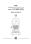
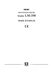
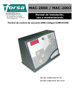
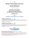
1
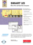
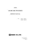
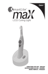
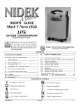
GYC-1000 Training Table of Contents 1. Safety 2. Outline, Principles 3. Specifications 4. Operation 5. Installation : Slit、Delivery、Check Power 6. Light control and Current control 7. Output power 8. Fiber alignment 9. Optical Axis 10. Adjusting Light Control 11. Over Power 12. Block Diagram 13. Replacement 14. Troubleshooting 1. Safety Operators Manual Classifications Safety Warning 2. Outline(Operators Manual)→Power、Laser Head、Wave Length Principles (Operators Manual ) 3. Specifications Operators Manual (9-1,9-2) Power : 50mW-1700mW Time : 0.01sec.-3.00sec. Wavelength :532nm Laser Power :2.5W @ 11.0-15.0A Beam Diameter:30um-40um Transmittance of fiber:90% 4. Operation Control box 5. Installation : Slit、Delivery、Check Power a. 100V / single phase b. Check Slit Lamp confirm the adjust bar position Confirm the aiming focus on 500um and 50um Coaxial between 50um and 500um c. Dip switch function e. Parameter settings(Technical Bulletin/ Rom Version) f. Check Focus of Aiming Beam g. Check power by burn paper Spot Size Power Time Result 200um 200mW 0.2sec Check burn spot over 80% 50um 1000mW 0.02sec Laser pass through on second shoot h. Check actual power at delivery end by power meter. *Need to perform the fiber alignment, over power and power check. *You must use electrical static protect service kit *Before you install the fiber optics, you must clean the fiber surface. Fiber alignment Service Manual 7.5.5 Over Power Service Manual 7.6.3 Power check Service Manual 7.6.1 7. Shutter Unit 8. Optical Axis for Laser Beam and coaxial between aiming beam and laser beam. 9. Output Power Settings *Dip switch 1, 2 and 4 up *Display 1700mW *Remove the fiber optics Check the Output Power at end of shutter unit. Over 2.4W 10. Fiber Alignment See Service Manual Note: Loosen set screw Mark the focus lens holder before remove Rotate the fiber connector after align Difference of X-Y stage on GYC-1500 and GYC-2000 11. Adjusting the Light Control See service manual Power calibration for each delivery by parameter Check the output power by Power Meter 12.Adjusting the over power See service manual : Page 5-9 *Note - Set the dip switches 1,2 and 5 - Dip switch Pack->See Service Manual Page 7-8 13.Block Diagram / Wiring Diagram See service manual : 8.1 Input – Power Supply Board(12V,5V) Peltie(5V) Main Board(12V,15A) System(12V) Laser Diode(5V,23A) 14. Replacement Master Board Power Supply Board 15. Trouble shooting Parameters : See Service Manual Error Code : See Service Manual Inter lock : See Service Manual Other indications : See Service Manual Check the laser head condition by service mode Power down Objective lens Aiming shutter Dichroic mirror Aiming diode Coag shutter Beam spritter Beam spritter 1st Photo detector TP9(TP5) 2nd Photo detector TP8(TP4) Prism TP8 TP9 Main Board Laser Head TP4 TP5 Memo At Current Control Display 1000mW=5A Display 2000mW=10A Display 3000mW=15A Display 4000mW=20A NIDEK GREEN LASER PHOTOCOAGULATOR Model GYC-1000 SERVICE MANUAL January 22, 2004 Pages in total: 68 XGYC4*RDA001A/E This page is intentionally vacant. Table of Contents §1 INTRODUCTION .........................................................................................................Page 1-1 §2 SAFETY ......................................................................................................................... 2-1 2.1General precautions ..................................................................................................... 2-1 2.2 Cautions in maintenance .............................................................................................. 2-1 2.3 Cautions in adjustment ................................................................................................ 2-2 §3 TROUBLESHOOTING ............................................................................................... 3-1 §4 SUB-TROUBLESHOOTING ...................................................................................... 4-1 4.1The LINE indicator does not light up. ........................................................................... 4-1 4.2 The fan does not work. ............................................................................................... 4-1 4.3 INTERLOCK 6.3 appears. ........................................................................................ 4-2 4.4 Error 1 appears. ......................................................................................................... 4-2 4.5 Error 3 appears. ......................................................................................................... 4-3 4.6 Error 13 appears. ....................................................................................................... 4-3 4.7 Error 20 appears. ....................................................................................................... 4-4 4.8 Error 21 appears. ....................................................................................................... 4-4 4.9 Error 54 appears. ....................................................................................................... 4-5 4.10 Any error in the 90s appears. .................................................................................... 4-5 4.11 INTERLOCK 4.7 appears. ...................................................................................... 4-6 4.12 The coagulation power cannot be changed. ............................................................... 4-6 4.13 The coagulation time cannot be changed. ................................................................... 4-7 4.14 The brightness of the aiming beam cannot be changed. ............................................... 4-7 4.15 The aiming beam is invisible. ..................................................................................... 4-7 4.16 The interval time cannot be changed. ......................................................................... 4-7 4.17 The READY indicator does not light up. .................................................................... 4-7 4.18 The counter cannot be reset. ..................................................................................... 4-7 4.19 Error 2 appears. ....................................................................................................... 4-8 4.20 Error 53 appears. ..................................................................................................... 4-9 4.21 Error 55 appears. ..................................................................................................... 4-9 4.22 INTERLOCK 2.7 appears. ...................................................................................... 4-9 4.23 Error 10 appears. ................................................................................................... 4-10 4.24 Error 15 appears. ................................................................................................... 4-10 4.25 The power output is out of the specified range. ........................................................ 4-11 4.26 When the spot size is set to 50µm, the power output is out of the specified range. ..... 4-11 4.27 The emergency stop switch cannot be activated. ...................................................... 4-12 §5 REMOVING COVERS ................................................................................................ 5-1 5.1 Removing covers ........................................................................................................ 5-1 §6 REPLACEMENT ......................................................................................................... 6-1 6.1 Replacing the switching power supply ......................................................................... 6-1 6.2 Replacing the fan ........................................................................................................ 6-1 6.3 Replacing the COAG shutter ...................................................................................... 6-2 6.4 Replacing the COAG SHUTTER ASSY ..................................................................... 6-3 6.5 Replacing the AIMING shutter ................................................................................... 6-3 6.6 Replacing the AIMING SHUTTER ASSY .................................................................. 6-4 6.7 Replacing the TRANSISTOR ..................................................................................... 6-4 6.8 Replacing the FIBER SW ........................................................................................... 6-4 6.9 Replacing the CPU ..................................................................................................... 6-5 6.10 Repairing and replacing the CB ASSY ...................................................................... 6-5 6.11 Replacing the LD ASSY ........................................................................................... 6-6 6.12 Replacing the DELIVERY BOARD .......................................................................... 6-6 6.13 Replacing the monitor ASSY .................................................................................... 6-7 6.14 Replacing the EMERGENCY switch ........................................................................ 6-7 6.15 Replacing the MASTER BOARD ............................................................................. 6-8 6.16 Replacing the LASER HEAD ................................................................................... 6-9 §7 ADJUSTMENT ............................................................................................................ 7-1 7.1 Setting parameters ...................................................................................................... 7-1 7.2 Adjustment of the MASTER BOARD ........................................................................ 7-1 7.2.1 Initial setting of the MASTER BOARD .............................................................. 7-1 7.2.2 Adjustment for Peltier device ............................................................................. 7-2 7.2.3 Current adjustment of the limiter ........................................................................ 7-4 7.3 Connection check of the laser head ............................................................................. 7-5 7.4 Operation check of the shutter .................................................................................... 7-6 7.4.1 Operation check of the COAG SHUTTER ASSY ............................................. 7-6 7.4.2 Operation check of the AIMING SHUTTER ASSY .......................................... 7-6 7.5 Optical adjustment ...................................................................................................... 7-7 7.5.1 Optical axis adjustment of green laser ................................................................ 7-7 7.5.2 Optical axis adjustment of aiming beam .............................................................. 7-8 7.5.2.1 Near point confocal adjustment ............................................................. 7-8 7.5.2.2 Far point confocal adjustment ................................................................ 7-8 7.5.3 1W and 1V adjustment ..................................................................................... 7-9 7.5.4 Condenser adjustment ....................................................................................... 7-9 7.5.5 Laser alignment for the fiber optic cable ........................................................... 7-10 7.6 Total adjustment ....................................................................................................... 7-11 7.6.1 Adjustment of the light control .......................................................................... 7-11 7.6.2 Power adjustment of the aiming beam .............................................................. 7-12 7.6.3 Adjustment for overpower ............................................................................... 7-13 7.6.3.1 Adjustment at 1000mW ...................................................................... 7-13 7.6.3.2 Adjustment at 50mW .......................................................................... 7-14 7.6.4 Check of overpower ....................................................................................... 7-15 7.6.5 Adjustment of the COAG TIME and REPEAT TIME ...................................... 7-16 §8 REFERENCES ............................................................................................................. 8-1 8.1 Wiring diagram ........................................................................................................... 8-1 8.2 Connectors and cables ............................................................................................... 8-2 8.3 Configuration ............................................................................................................ 8-10 8.4 Labels ...................................................................................................................... 8-11 8.5 List of replacement parts ........................................................................................... 8-14 8.6 Tools........................................................................................................................ 8-14 8.7 DIP switches ............................................................................................................ 8-15 8.8 Error code table ....................................................................................................... 8-15 8.9 INTERLOCK code table ......................................................................................... 8-16 8.10 Other messages ...................................................................................................... 8-16 8.11 Special key operations ............................................................................................ 8-16 This page is intentionally vacant. §1 INTRODUCTION This service manual contains service instructions for the NIDEK GREEN LASER PHOTOCOAGULATOR, GYC-1000. For correct service, thorough understanding of the contents of this manual is required prior to the service. Use this manual together with the GYC-1000 Operator’s Manual and Parts List. The specifications and design of this instrument are subject to change without notice for improvement. In the case of major changes, refer to the corresponding TECHNICAL BULLETIN issued in each occasion. If the instrument cannot be repaired by repair operations in accordance with this Service Manual, please inform NIDEK of the Serial Number of the instrument, and details of the symptom. This page is intentionally vacant. §2 SAFETY 2.1 General precautions • Only NIDEK service persons and persons trained by NIDEK for the GYC-1000 service work are allowed to repair the instrument. • Observe the procedures to perform the repair work. If not, accidents or failure of the instrument may result. • When performing the maintenance work, turn OFF the power switch, and disconnect the power cord from the wall outlet unless the power needs to be ON. 2.2 Cautions in maintenance • Take action against static electricity before service work. • In case of instrument malfunction, turn OFF the power switch after checking the symptom. • Never drop parts or screws inside the instrument, nor bump it against surrounding objects. • Prepare storage cases so as not to lose the removed screws or parts. • Screw or unscrew the screws with proper tools. • After loosening the screws fixed by a thread-locking adhesive, be sure to reapply the threadlocking adhesive to the screws when you retighten them. • After replacing parts, make sure that they are fixed securely before turning ON the power. • If you observe strange odors or smoke being issued from the instrument, immediately turn OFF the instrument, disconnect the power cord from the outlet, and diagnose the cause. If the instrument is powered in abnormal conditions, fire, electric shock or total loss of the instrument may result. • Refer to “8.1 Wiring diagram” and “8.2 Connectors and cables,” for checking cable breaks as described in “§4 SUB-TROUBLESHOOTING”. In addition, check cables for the following: Connectors are connected and crimped securely. No contact failure occurs after re-connection of connectors. Cables are soldered properly. • Do not pull the cables strongly. Cable breaks etc. may result. 2-2 • Never perform continuous emission for more than 10 seconds because this puts an enormous load on the power supply. • Never emit the laser beam onto reflective objects such as a metal surface. • Wear the safety goggles for the GYC-1000. • Never emit the laser beam (direct light) to a human body or any object. 2.3 Cautions in adjustment • Perform adjustment on a vibration-free, stable and level surface. A slanted floor or place subject to vibration will obstruct accurate adjustment. • Do not use a calibration jig for usage other than described in this manual. §3 TROUBLESHOOTING Turn ON the master switch. Does the LINE indicator light up? No 4.1 The LINE indicator lights up. Yes Does the LASER EMISSION indicator light No up by turning ON the key switch and does the system start a countdown for 10 seconds? 4.3 INTERLOCK 6.3 appears. Yes Does the fan work? No Yes After the countdown, do the POWER and TIME displays indicate the setting values? No Yes Can the coagulation power output be set properly? 4.2 The fan does not work. 4.4 Error 1 appears. 4.5 Error 3 appears. 4.6 Error 13 appears. 4.7 Error 20 appears. 4.8 Error 21 appears. 4.9 Error 54 appears. 4.10 Any error in the 90s appears. 4.11 INTERLOCK 4.7 appears. No 4.12 The coagulation power cannot be changed. No 4.13 The coagulation time cannot be changed. Yes Can the coagulation time be set properly? Yes Can the brightness of the aiming beam changed by pressing the AIMING switch? No Yes Does the indication on the INTERVAL display light up by pressing the INTERVAL switch? Yes No 4.14 The brightness of the aiming beam cannot be changed. 4.15 The aiming beam is invisible. 4.16 The interval time cannot be set. 3-2 This page is intentionally vacant. Does the READY indicator light up by pressing the STATUS switch? No 4.17 The READY indicator does not light up. No 4.18 Counter cannot be reset. Yes Is the indication on the COUNTER display reset to “0” by pressing the RESET switch? Yes Is the laser emitted by depressing the foot switch? No Yes Is the measured power output within the specifications for the set values? No Yes Do the laser emission stop, the indications of No the control box light off, and the fan stop by pressing the emergency stop switch? Yes Turn ON the key switch. After the countdown for 10 seconds, turn OFF the key switch. Turn OFF the master switch. Completion of operation 4.19 Error 2 appears. 4.20 Error 53 appears. 4.21 Error 55 appears. 4.22 INTERLOCK 2.7 appears. 4.23 Error 10 appears. 4.24 Error 15 appears. 4.25 The power output is out of the specified range. 4.26 When the spot size is set to 50μm, the power output is out of the specified range. 4.27 The emergency stop switch cannot be activated. §4 SUB-TROUBLESHOOTING 4.1 The LINE indicator does not light up. Is the fuse in the fuse carrier blown? Yes Replace the fuse with a new one. (Refer to the Operator’s Manual.) No Is the voltage between the 1st and 3rd pins of No P125 on the MASTER BOARD + 12 VDC? Replace the switching power supply. (See “6.1”.) Yes Is the voltage between the 24th and 20th pins No of J108 on the MASTER BOARD approximately + 4.0 VDC? Replace the MASTER board. (See “6.15”.) Yes Does the cable between the 20th and 24th Yes pins of the CB CABLE ASSY have a break? Repair the faulty point. No Replace the DISPLAY BOARD. (See “6.15”.) 4.2 The fan does not work. * The fan does not work when the temperature is lower than the specified one (25 degrees C). Does the LINE indicator of the control box light up? No Check the articles described in “4.1 The LINE indicator does not light up.” (See “4.1”.) Yes Is the voltage between the 1st and 2nd pins of No J112 on the MASTER BOARD + 12 VDC? Yes Replace the FAN ASSY. (See “6.2”.) Replace the MASTER BOARD. (See “6.15”.) 4-2 4.3 INTERLOCK 6.3 appears. Is the REMOTE connector connected? No Connect the REMOTE connector. Yes Is electricity applied between the 3rd and 4th No pins of the REMOTE connector? Yes Repair the faulty point between the 3rd and 4th pins of the REMOTE connector, or replace the REMOTE connector. Replace the MASTER BOARD. (See “6.15”.) 4.4 Error 1 appears. Does the COAG SHUTTER ASSY (EA04) have a break? Yes Repair or replace the COAG SHUTTER ASSY (EA04). (See “6.4”.) No Is the COAG SHUTTER ASSY positioned at No the detectable area of the sensor? Perform the position adjustment of the COAG SHUTTER ASSY. Yes Is the voltage between the 3rd and 7th, 4th No and 7th pins of P106 (J106) on the MASTER BOARD approximately + 1.3 DVC? Replace the COAG SHUTTER ASSY (EA04). (See “6.4”.) Yes Is the voltage of P106 (J106) on the MASTER BOARD as follows when the COAG shutter is closed? TP17: 5 V TP18: 0 V No Repair or replace the COAG SHUTTER ASSY (EA04). (See “6.4”.) No Repair or replace the COAG SHUTTER ASSY (EA04). (See “6.4”.) Yes Is the voltage of P106 (J106) on the MASTER BOARD as follows when the COAG shutter is open? TP17: 0 V TP18: 5 V Yes Replace the MASTER BOARD. 4-3 4.5 Error 3 appears. Does the AIMING SHUTTER ASSY (EA03) Yes have a break? Repair or replace the AIMING SHUTTER ASSY (EA03). (See 6.6.) No Is the AIMING SHUTTER ASSY positioned No at the detectable area of the sensor? Perform the position adjustment of the AIMING SHUTTER ASSY. Yes Is the voltage between the 3rd and 5th, 6th No and 5th pins of P107 (J107) on the MASTER BOARD approximately + 1.3 DVC? Replace the AIMING SHUTTER ASSY (EA03). (See 6.4.) Yes Is the voltage of P107 (J107) on the MASTER BOARD as follows when the aiming beam is OFF? 4th - 5th pins: 5 V 7th - 5th pins: 0 V No Repair or replace the AIMING SHUTTER ASSY (EA03). (See 6.6.) No Repair or replace the AIMING SHUTTER ASSY (EA03). (See 6.6.) Yes Replace the TRANSISTOR ASSY. (See 6.7.) Yes Replace the TRANSISTOR ASSY. (See 6.7.) Yes Is the voltage of P107 (J107) on the MASTER BOARD as follows when the aiming beam is ON? 4th - 5th pins: 0 V 7th - 5th pins: 5 V Yes Replace the MASTER BOARD. 4.6 Error 13 appears. Disconnect P113 (J113) on the MASTER BOARD. Is the circuit between the 1st and 3rd pins of P113 on the TRANSISTOR ASSY short-circuited? No Disconnect P114 (J114) on the MASTER BOARD. Is the circuit between the 1st and 3rd pins of P114 on the TRANSISTOR ASSY short-circuited? No Replace the MASTER BOARD. (See 6.15.) 4-4 4.7 Error 20 appears. Does the LH CABLE ASSY have a break? Yes Repair or replace the LH CABLE ASSY. No Replace the laser head. (See 6.16.) No Replace the laser head. (See 6.16.) Yes Repair or replace the LH CABLE ASSY. No Replace the laser head. (See 6.16.) No Replace the laser head. (See 6.16.) No Disconnect P123 (J123) on the MASTER BOARD. Is the resistance between the 1st and 2nd pins of P123 of the LH CABLE ASSY 6 - 12 KΩ? Yes Replace the MASTER BOARD. (See 6.15.) Is the symptom improved? Yes Completion of operation 4.8 Error 21 appears. Does the LH CABLE ASSY have a break? No Disconnect P123 (J123) on the MASTER BOARD. Is the resistance between the 3rd and 2nd pins of P123 of the LH CABLE ASSY 8 - 12.5 KΩ? Yes Replace the MASTER BOARD. (See 6.15.) Is the symptom improved? Yes Completion of operation 4-5 4.9 Error 54 appears. Can the FIBER SW be turned ON when the fiber optic cable plug is connected? No Perform the position adjustment of the FIBER SW. Yes Is electricity applied between the 2nd and 3rd, No 5th and 6th pins of P105 when the micro switch of the FIBER SW ASSY (EA01) is turned ON? Replace the FIBER SW ASSY (EA01). (See 6.8.) Yes Disconnect P105 (J105) on the MASTER BOARD. Is the voltage of J105 as follows? 2nd - 3rd pins: 5 V 5th - 6th pins: 5 V No Replace the MASTER BOARD. (See 6.15.) Yes Completion of operation 4.10 Any error in the 90s appears. Replace the MAIN CPU (17164-E150) and SUB CPU (17164-E160). (See 6.9.) 4-6 4.11 INTERLOCK 4.7 appears. Does the fan work? No Check the articles described in “4.2 The fan does not work.” (See “4.2”.) No Move the object which blocks the air vent, or move the instrument. No Make the temperature of the room the same as the specified. No Replace the MASTER BOARD. (See 6.15.) Yes Does any object block the air vent of the instrument? Yes Is the temperature of the room within the specified range (10 - 30℃) for usage? Yes Leave the instrument for 30 minutes or longer for natural cooling. Can the instrument be used without INTERLOCK 4.7 when restarting the instrument? Yes The instrument is normal. Although INT4.7 appeared because the temperature of the instrument temporarily rose. The temperature of the instrument has lowered now and the instrument can be used. 4.12 The coagulation power cannot be changed. Turn OFF the key switch. After the indications of the control box go off, turn ON the key switch again. Is the voltage between the 16th and 18th, 17th No and 19th pins of P108 (J108) of the MASTER BOARD 5 V? Replace the MASTER BOARD. (See 6.15.) Yes Does the CB CABLE ASSY (EA13) have a faulty soldering or break? No Replace the MASTER BOARD. (See 6.15.) Yes Repair or replace the CB CABLE ASSY. (See 6.10.) 4-7 4.13 The coagulation time cannot be changed. Check and perform the articles described in 4.12. 4.14 The brightness of the aiming beam cannot be changed. Check and perform the articles described in 4.12. 4.15 The aiming beam is invisible. Does the aiming shutter block the optical path? Yes Adjust the operation of the AIMING SHUTTER ASSY. No Is the voltage between the TP12 and GND on No the MASTER BOARD 1.2 V, and is the aiming beam emitted from the AIMING LD ASSY (EA02)? Replace the AIMING LD ASSY. (See 6.11.) Yes Can the aiming beam be seen by turning VR1 No on the MASTER BOARD clockwise? Replace the MASTER BOARD. (See 6.15.) Yes Adjust the power output of the aiming beam. (See 7.6.2.) 4.16 The interval time cannot be changed. Check and perform the articles described in 4.12. 4.17 The READY indicator does not light up. Check and perform the articles described in 4.12. 4.18 The counter cannot be reset. Check and perform the articles described in 4.12. 4-8 4.19 Error 2 appears. Is the connector of the delivery unit No connected to P702 (J702) on the DELIVERY BOARD (17621-E4965)? Connect the connector of the delivery unit to P702 (J702) on the DELIVERY BOARD. Yes Does the delivery setting of the main body coincide with the connected delivery unit? No Select the proper delivery setting of the main body. Yes Repair or replace the DELIVERY BOARD ASSY (EA08). (See 6.12.) No Replace the MASTER BOARD. (See 6.15.) No The delivery unit malfunctions. (Refer to the Service Manual of the delivery unit.) No The delivery unit malfunctions. (Refer to the Service Manual of the delivery unit.) Yes Does the DELIVERY BOARD ASSY (EA08) have a break? No Is the voltage of P104 (J104) on the MASTER BOARD as follows? 11th - 12th pins: About + 15 V Yes Is the voltage of TP on the MASTER BOARD as follows? TP14: 0 V TP15: 5 V Yes Is the voltage of TP on the MASTER BOARD as follows when the filter is open? TP14: 5 V TP15: 0 V Yes Replace the MASTER BOARD. (See 6.15.) 4-9 4.20 Error 53 appears. Does the FOOT SW ASSY (EA11) have a break? Yes Repair or replace the FOOT SW ASSY (EA11). Yes Adjust the switch in the foot switch. No Does Err.53 occur when depressing the foot switch slowly? No Is electricity applied between the 1st and 4th, 3rd and 4th pins of P101 (J101) on the No MASTER BOARD when the foot switch is depressed? Replace the foot switch (10149-0000). Yes Replace the MASTER BOARD. (See 6.15.) 4.21 Error 55 appears. Check and perform the articles described in 4.19. 4.22 INTERLOCK 2.7 appears. Does the 1st MONITOR of the POWER MONITOR ASSY (EA05) have a break? Yes Repair or replace the POWER MONITOR ASSY (EA05). No Measure the actual power output at the aperture of the delivery unit. Is the measured Yes power output within the specified range? [Specified power] 90 mW or less: ±20% 100 mW or more: ±15% Adjust the power output at the aperture of the delivery unit until it becomes within the specified range. (See 7.6.1.) No Perform the adjustment for the overpower. (See 7.6.3.) Is the symptom improved? No Replace the MASTER BOARD. (See 6.15.) Yes Completion of operation 4 - 10 4.23 Error 10 appears. Does the LD CABLE ASSY (EA19) have a break? Yes Repair or replace the LD CABLE ASSY (EA19). (See 6.13.) No Does the POWER MONITOR ASSY (EA05) Yes have a break? Repair or replace the POWER MONITOR ASSY (EA05). (See 6.13.) No Replace the laser head. (See 6.16.) 4.24 Error 15 appears. Does the 2nd MONITOR of the POWER MONITOR ASSY (EA05) have a break? Yes Replace the POWER MONITOR ASSY. (See 6.13.) Yes Perform the adjustment for overpower. (See 7.6.3.) No Replace the laser head. (See 6.16.) Yes Completion of operation No Measure the power output at the aperture of the delivery unit. Is the actual power output within the specified range? [Specified power] 90 mW or less: ±20% 100 mW or more: ±15% No Adjust the power output at the aperture of the delivery unit until it becomes within the specified range. (See 7.6.1.) Measure the power output at the aperture of the delivery unit. Is the power output adjusted so that it becomes within the specified range? Yes Perform the adjustment for overpower. (See 7.6.3.) Is the symptom improved? No Replace the MASTER BOARD. (See 6.15.) 4 - 11 4.25 The power output is out of the specified range. Is the laser alignment for the fiber optic cable Yes proper? No Does the burn pattern have any unburnt area? Perform the laser alignment for the fiber optic cable properly. (See 7.5.5.) Yes Replace the fiber optic cable or laser head. (See 6.16.) No Replace the fiber optic cable. Yes Replace the MASTER BOARD. (See 6.15.) Yes Replace the laser head. (See 6.16.) No Is the transparency of the fiber optic cable 90% or more? Yes Adjust the coagulation power output. (See 7.6.1.) Is the power output too high? No Is the power output too low? No Completion of operation 4.26 When the spot size is set to 50µm, the power output is out of the specified range. Adjust the power output when the spot size is set to 50µm. (See 7.6.1.) 4 - 12 4.27 The emergency stop switch cannot be activated. Is electricity between the 3rd and 4th, 5th and 6th pins of P301 of the EMERGENCY SW No ASSY (EA21) as follows? EMERGENCY SW is ON: Not applied EMERGENCY SW is OFF: Applied Repair or replace the EMERGENCY SW ASSY (EA21). (See 6.14.) Yes Does the CB CABLE ASSY (EA13) have faulty soldering? No Replace the MASTER BOARD. (See 6.15.) Yes Repair or replace the CB CABLE ASSY. (See 6.10.) 7-7 7.5 Optical adjustment 7.5.1 Optical axis adjustment of green laser 1. Remove the following parts of the CONDENSER ASSY (17164-1700) according to the right figure. (a) Mount (17164-M110) (b) Receptacle (17164-M107) (c) Plate (17164-M111) (d) Pin (17164-M115) (e) Base (17164-M105) (f) Spring (17164-M109) 5$ 2. Connect the clamp tester to the 2 BRN cables of J117 (+5V PS ASSY: 17164-EA16) on the MASTER BOARD (17164-BA01). Set DIP SW No. 6 on the CB (17164-BA03) to the OFF position, and turn ON the master and key switches. %- %- 3. Set the power meter (COHERENT, Model 201) to the laser beam window (receptacle of the main body). 4. Adjust the current by pressing the POWER switch on the CB so that the clamp tester reads the same current as the one (2.5W) in the Shipping Record when emitting the laser. At the same time, verify that the power meter reads 2.3W or more. 5$ Vertical position adjustment 5. Attach the near point optical axis calibration jig (19344-M910) to the attached position of the receptacle (17164-M107). 6. Loosen SB3×12 (n=6) (illustrated on the right figure), and adjust the vertical and horizontal positions so that the optical axis of the green laser coincides with the center of the near point optical axis calibration jig. 5$ Horizontal position adjustment 7-8 7.5.2 Optical axis adjustment of aiming beam 1. Loosen HH3×6 and turn the LD (17164EA02) to adjust the optical axis of the aiming beam so that the shape of the aiming beam becomes lateral as illustrated on the right when matching the aiming beam position to the near point optical axis calibration jig (19433-M910). * The optical axis adjustment of the aiming beam described above is a rough adjustment. Turn the LD. The shape of the AIMING beam is lateral. ** 7.5.2.1 Near point confocal adjustment 1. Follow the instructions below to adjust the LD ASSY (17164-1600) so that the optical axis of the aiming beam coincides with the center of the near point optical axis calibration jig (19433-M910) and so it coincides with the green laser coaxially. (1) Loosen SB3×8 (n=2) and adjust the 5$ 5$ horizontal position of the LD ASSY (171641600) at the position of the base (17164M088). (2) Loosen SB3×12 (n=2) and adjust the vertical 5$ position of the LD ASSY (17164-1600). (3) Fasten and unfasten SB3×15 (n=4), and finely adjust the vertical and horizontal position of the LD ASSY (17164-1600). . 7.5.2.2 Far point confocal adjustment 1. Emit the laser to a wall that is 1m or more away from the instrument. Follow the instructions below to adjust the DICHROIC ASSY (17164-1400) so that the aiming beam coincides ** with the green laser coaxially. (1) Loosen SB3×10 (n=2) and move the DICHORIC ASSY horizontally, forward and ** backward to adjust the position of the 5$ DICHORIC ASSY (17164-1400) with the 5$ play of the screw. 5$ (2) Loosen SB2×5 (n=2), and fasten and unfasten HH3×6 (n=2) to adjust the horizontal position of the DICHORIC ASSY (17164-1400). (3) Fasten and unfasten HH3×6 and SB3×12 to &+%*14+%#55; adjust the vertical position of the DICHORIC ASSY (17164-1400). 2. Perform the near point (see 7.5.2.1) and far point confocal adjustment repeatedly so that the aiming beam coincides with the green laser coaxially at the near point and far point. 7-9 7.5.3 1W and 1V adjustment 1. Remove the parts of the CONDENSER ASSY (17164-1700) that are the same as the parts removed in 7.5.1. (See 7.5.1.) * Before removing the parts, verify that the optical axis of the green laser coincides with the center of the near point optical axis calibration jig (19433-M910). (See 7.5.1.) 2. Turn OFF the master and key switches. Connect the oscilloscope between TP8 and TP9, and turn ON the master and key switches. 3. Press the POWER switch on the CB to set the laser power so that the power at the end of the laser becomes 1000mW when emitting the laser. 4. Follow the instructions below to adjust the voltage so that the voltage of TP8 and TP9 becomes 1V when emitting the laser. (a) Voltage of TP8: Adjust it with VR6 on the MASTER BOARD (17164-B01). (b) Voltage of TP9: Adjust it with VR3 on the MASTER BOARD (17164-BA01). * If the voltage cannot be adjusted to 1V, remove the MONITOR ASSY (17164-1200) from the bench (17164-M001), insert 3PW3 (n=2) between the MONITOR ASSY (17164-1200) and bench (17164-M001), and adjust the position of the MONITOR ASSY (17164-1200). Then, check the voltage again. 5. Set DIP SW No. 1 and 2 on the CB (17164-BA03) to the OFF position. 6. Connect the oscilloscope to TP8 on the MASTER BOARD (17164-BA01). 7. Verify that the waveform of TP8 by the oscilloscope does not have any overshooting, noise etc. when emitting the laser at the POWER of 500mW and 50mW. 8. Set DIP SW No. 1 and 2 on the CB (17164-BA03) to the ON position. 7.5.4 Condenser adjustment 1. Attach the receptacle (17164-M107) that was 5$ removed in the green laser optical axis adjustment. (See 7.5.1.) 2. Set the power meter (COHERENT Model 201) in front of the laser beam window of the main body. Press the POWER switch on the CB to adjust the laser power so that the power meter reads 500mW. Take notes of the measured power and the power on the POWER display of the CB. 3. Connect the condensed laser magnification %- jig (19344-9100) to the FIBER connector 5$ (receptacle: 17164-M107) of the main body. 4. Loosen SB3×12 and lock rings (17162-M070, n=2) of the adjustment screws (17164-M112, n=2). 5. First, lower the laser power by pressing the POWER switch, then gradually increase it until the laser slightly lights up. 6. Emit the laser and turn the adjustment screws (17164-M112, n=2) so that the position of the green laser coincides with the center of the condensed laser magnification jig (194339100). 7. Connect the fiber optic cable to the base (17164-M105) and FIBER connector of the main body (receptacle: 17164-M107) together with the condenser. Set the power meter to the end of the fiber optic cable. 8. Set the POWER of the CB to the same power as in step 2. 7 - 10 9. Emit the laser and follow the instructions ;CZKU below to adjust the adjustment screw of each axis and holder so that the power meter reads the maximum power. (1) Turn the adjustment screw for the X axis (17164-M112) to adjust its position so that the power meter reads the maximum power. (2) Turn the adjustment screw for the Y axis (17164-M112) to adjust its position so that the power meter reads the maximum power. (3) Push and draw out the holder to adjust its position so that the power meter reads the maximum power. :CZKU (4) Repeat steps (1) to (4). 10. Emit the laser and verify that the power measured by the power meter is 90% or more of the power obtained in step 2. * If it is not, perform step 9 again. 11. Make the fiber optic cable turn one rotation at 90 degree intervals. Verify that the measured power at every 90 degrees is 90% or more of the power obtained in step 10. * If it is not, perform step 9 again. 12. Screw SB3×12 and lock rings (17162-M070) of the adjustment screws (17164-M112). Then, perform steps 10 and 11 again. 13. After the condenser adjustment is completed, reassemble the plate (17164-M111), pin (17164-M115), mount (17164-M110) and spring (17164-M109). 7.5.5 Laser alignment for the fiber optic cable * Follow the instructions below to perform the laser alignment for the fiber optic cable only when the laser alignment for the fiber optic cable has shifted. 1. Loosen SB3×12 and lock rings (17164-M070). (See 7.5.4.) 2. Attach the fiber optic cable to the CONDENSER ASSY (17164-1700), set the laser power output to 500mW and emit the laser onto a wall etc. 3. Turn the adjustment screws for the X and Y Center of the laser beam Periphery of the axes (17164-M112) so that the periphery of burn pattern the burn pattern on the wall etc. fades out (lightly burnt). 4. Set the power meter to the end of the fiber optic cable. 5. Turn the adjustment screws for the X and Y axes (17164-M112) to adjust the position so that the power meter reads the maximum. 6. Perform step 5 repeatedly to adjust the position finely so that the power meter reads the maximum laser power. 7. Make the fiber optic cable turn one rotation at 90 degree intervals. Verify that the measured power at every 90 degrees is 90% or more of the power obtained in step 6. 8. Tighten SB3×12 and the lock rings (17164-M112) of the adjustment screws. Then, perform step 7 and verify that the measured power is 90% or more. * If it is not, repeat steps 5 to 8. 7 - 11 7.6 Total adjustment 7.6.1 Adjustment of the light control 1. Set DIP SW No. 1 and 2 on the CB to the OFF position, and No. 3 to 8 to the ON position. 2. Detach the fiber optic cable and set the value of parameter address 24 to “100”. (See 7.1.) 3. Attach the fiber optic cable and set the power meter (COHERENT Model 201) to the end of the fiber optic cable. 4. Follow the instructions below to adjust the POWER display of the CB and the power measured by the power meter when the POWER display of the CB is 50mW and 500mW. At the power of 500mW: Adjust the value with VR3 on the MASTER BOARD (17164-BA01). At the power of 50mW: Adjust the value with parameter address 18. * Firstly, perform the adjustment at the power of 500mW. Then, perform the adjustment both at the power of 500mW and 50mW so that the POWER display of the CB and the measured power do not shift. 5. Turn OFF the key switch and attach the fiber optic cable of each delivery unit to the main body. 6. Set the power meter (COHERENT Model 201) to each delivery unit. 7. Measure the power output of each delivery unit when the POWER display of the CB is 500mW. Follow the instructions below to adjust the power so that the measured power becomes 500mW ± 15%. (1) Set DIP SW No. 6 of the CB to the OFF position. (2) Change the parameters below. (See 7.1.) SL-130 delivery unit : Parameter address 20 SL-1600/30SL delivery unit : Parameter address 21 Other delivery units : Parameter address 23 ENDO delivery unit : Parameter address 24 BIO delivery unit : Parameter address 26 HAAG delivery unit : Parameter address 27 COMBO delivery unit : Parameter address 28 (3) Set DIP SW No. 6 of the CB to the ON position. Power of the fiber Address (4) Measure the power output again, repeat steps optic cable At 100mW 30 (1) to (4) until the power output becomes At 200mW 31 500mW ± 15%. At 300mW 32 * Set the spot size of each delivery unit to At 400mW 33 the maximum. At 500mW 34 At 600mW 35 * If the power output is 500mW ± 15%, it At 700mW 36 is not necessary to change the parameters. At 800mW 37 8. Measure the power output when the POWER At 900mW 38 display of the CB is 100 to 1700mW. At 1000mW 39 At 1100mW 40 9. Adjust the power output with the parameter At 1200mW 41 addresses 30 to 46 as in the right table so At 1300mW 42 that the power output becomes 100 At 1400mW 43 1700mW ± 15%. (See 7.1.) At 1500mW 44 At 1600mW 45 * Set the spot size of each delivery unit to the At 1700mW 46 maximum. 7 - 12 10. Measure the power output when the POWER display of the CB is 50mW, and adjust it with parameter address 18 so that it becomes 50mW ± 20%. (See 7.1.) 11. Set the spot size of each delivery unit to the minimum, and measure the power output when the POWER display of the CB is 50mW. 12. Adjust the power output with the parameter addresses below so that the measured power becomes 500mW ± 15%. (See 7.1.) SL-1600/30SL delivery unit : Parameter address 80 SL130 delivery unit : Parameter address 81 HAAG delivery unit : Parameter address 82 13. Verify that the power output is within the specified range for all conditions (spot size, POWER display of the CB). 14. Compensate for a shift in the power output according to the spot size by changing the parameter values finely until the power output becomes within the specified range. 15. Set the POWER display of the CB to 1700mW. Verify that the rising voltage of TP8 is within the range of the stable voltage ± 20% when depressing the foot switch. 16. After the adjustment is completed, set all the DIP switches of the CB (17164-BA03) to the ON position. 7.6.2 Power adjustment of the aiming beam 1. Set the power meter (LASER MATE Q 0217-050-00) to the delivery unit, and multimeter between TP12 on the MASTER BOARD (17164-BA01) and GND. Set the AIMING display of the CB and the spot size of each delivery unit to the maximum. 2. Adjust the optical axis of the aiming beam again while checking the power meter so that the power of the aiming beam becomes the maximum. (See 7.6.2.) 3. Adjust the power with VR1 on the MASTER BOARD (17164-BA01) so that the power output of the aiming beam becomes 0.3mW. 4. Verify that the voltage (obtained by the multimeter) between TP12 on the MASTER BOARD (17164-BA01) and GND is 1V or less. * The voltage is normally about 0.5V or so. 5. Set the AIMING display of the CB to the minimum. Change the value of parameter address 19 so that the power output of the aiming beam becomes 0.01mW or less. (See 7.1.) 6. Set the AIMING display of the CB to the minimum again. Verify that the power output of the aiming beam is 0.3mW. If not, perform steps 3 to 5. 7. Turn the fiber optic cable 360 degree and verify that the power varies within the range of ± 10%. 8. A shift in the POWER according to the spot size can be compensated for with the parameter. 9. Measure the power output of the aiming beam when the spot size is set to the maximum and minimum. Verify that the power output of the aiming beam is within the specified range for all conditions. 7 - 13 7.6.3 Adjustment for overpower 7.6.3.1 Adjustment at 1000mW 1. Set DIP SW No. 1, 2 of the CB to the OFF and No. 3 to 8 to the ON position. 2. Turn OFF the master and key switches. Set the oscilloscope by following the instructions below and turn ON the master and key switches. CH1: TP4 on the MASTER BOARD (17164-BA01) CH2: IC1 77th pin on the MASTER BOARD (17164-BA01) 3. Set the value of parameter address 57 to “9”. (See 7.1.) %* 4. Emit the laser at the POWER of 50mW and observe the waveform with the oscilloscope. Verify that the time-lag between CH1 and %* CH2 (when the signal becomes high) is 7 OUGEQTNGUU msec. or less. * Perform steps 3 and 4 only for the program Ver. 1.00. 5. Turn OFF the master and key switches. Set the oscilloscope by following the instructions below, and turn ON the master and key switches. CH1: TP9 on the MASTER BOARD (17164-BA01) CH2: TP8 on the MASTER BOARD (17164-BA01) 6. Set the POWER display of the CB to “1000mW” and turn VR6 on the MASTER BOARD (17164-BA01) to match the TP8 voltage with the TP9 voltage when emitting the laser. * The TP9 voltage is fixed. 7. Set the POWER display of the CB to +06.-QEEWTU “1000mW”. While emitting the laser, turn VR6 on the MASTER BOARD (1716462XQNVCIG BA01) so that the TP8 voltage becomes the 62XQNVCIG TP9 voltage + 20%. Adjust the value of parameter address 55 so that INTLK 2.7 62XQNVCIG (only a beep) occurs at that time. (See 7.1.) 8. Set the POWER display of the CB to “1000mW”. While emitting the laser, turn VR6 on the MASTER BOARD (1716462XQNVCIG BA01) so that the TP8 voltage becomes the 62XQNVCIG TP9 voltage -20%. Adjust the value of parameter address 58 so that Err. 15 (only a 62XQNVCIG beep) occurs at that time. (See 7.1.) 'TTQEEWTU 9. Turn VR6 on the MASTER BOARD (17164BA01) to match the TP8 voltage with the TP9 voltage when emitting the laser. 10. Set all DIP switches of the CB (17164-BA03) to the ON position. 7 - 14 7.6.3.2 Adjustment at 50mW 1. Set DIP SW No. 1, 2 of the CB (17164-BA03) to the OFF and No. 3 - 8 to the ON position. 2. Turn OFF the master and key switches. Set the oscilloscope to the terminals below and turn ON the master and key switches. CH1: TP5 on the MASTER BOARD (17164-BA01) CH2: TP4 on the MASTER BOARD (17164-BA01) 3. Turn VR6 on the MASTER BOARD (17164-BA01) to match the TP4 voltage with the TP5 voltage when emitting the laser. * The TP5 voltage on the MASTER BOARD (17164-BA01) is fixed. 4. Set the POWER display of the CB to “50mW”. While emitting the laser, turn VR6 on the MASTER BOARD (17164-BA01) so that the TP4 voltage becomes the TP5 voltage + 20%. Adjust the value of parameter address 56 so that INTLK 2.7 (only a beep) occurs at that time. (See 7.1.) 5. Set the POWER display of the CB to “50mW”. While emitting the laser, turn VR6 on the MASTER BOARD (17164-BA01) so that the TP4 voltage becomes the TP5 voltage -20%. Adjust the value of parameter address 59 so that Err. 15 (only a beep) occurs at that time. (See 7.1.) 6. Turn VR6 on the MASTER BOARD (17164BA01) to match the TP4 voltage with the TP5 voltage when emitting the laser. 7. Set all DIP switches of the CB (17164-BA03) to the ON position. +06.-QEEWTU 62XQNVCIG 62XQNVCIG 62XQNVCIG 62XQNVCIG 62XQNVCIG 62XQNVCIG 'TTQEEWTU 7 - 15 7.6.4 Check of overpower 1. Set all DIP switches of the CB to the ON position. 2. Turn OFF the master and key switches. Set the oscilloscope by following the instructions below and turn ON the master and key switches. CH1: TP9 on the MASTER BOARD (17164-BA01) CH2: TP8 on the MASTER BOARD (17164-BA01) 3. Set the POWER display of the CB to “1000mW”. While emitting the laser, turn VR6 on the MASTER BOARD (17164BA01) so that the TP8 voltage becomes the TP9 voltage -20%. Verify that Err. 15 occurs (laser emission is OFF, as well) at that time. 4. Set the POWER display of the CB to “1000mW”. While emitting the laser, turn VR6 on the MASTER BOARD (17164BA01) so that the TP4 voltage becomes the TP5 voltage + 20%. Verify that INTLK 2.7 occurs (laser emission is OFF, as well) at that time. 62XQNVCIG 62XQNVCIG 62XQNVCIG 'TTQEEWTU +06.-QEEWTU 62XQNVCIG 62XQNVCIG 5. Turn OFF the master and key switches. Set the oscilloscope to the terminals below and turn ON the master and key switches. CH1: TP5 on the MASTER BOARD (17164-BA01) CH2: TP4 on the MASTER BOARD (17164-BA01) 62XQNVCIG 6. Set the POWER display of the CB to “50mW”. While emitting the laser, turn VR6 on the MASTER BOARD (17164-BA01) so that the TP4 voltage becomes the TP5 voltage + 20%. Verify that INTLK 2.7 occurs (laser emission is OFF, as well) at that time. 7. Set the POWER display of the CB to “50mW”. While emitting the laser, turn VR6 on the MASTER BOARD (17164-BA01) so that the TP4 voltage becomes the TP5 voltage -20%. Verify that Err. 15 occurs (laser emission is OFF, as well) at that time. 8. Turn VR6 on the MASTER BOARD (17164BA01) to match the TP4 voltage when emitting the laser with the TP5 voltage. 9. After the adjustment is completed, verify with the oscilloscope that the waveforms at the powers of 50 - 1700mW match. +06.-QEEWTU 62XQNVCIG 62XQNVCIG 62XQNVCIG 62XQNVCIG 62XQNVCIG 62XQNVCIG 'TTQEEWTU 7 - 16 7.6.5 Adjustment of the COAG TIME and REPEAT TIME 1. Set the analyzing recorder (Model 3565) to the instrument. 2. Set the POWER display of the CB to “250mW” and TIME display to “0.01 sec”. 3. Emit the laser and adjust the value of parameter address 52 so that the measured value (COAG TIME) by the analyzing recorder becomes 0.01 sec. (See 7.1.) 4. Verify that the COAG TIME is within the specified range when the TIME display of the CB is set to 0.02 - 3.00 sec. [Specification of COAG TIME] 0.01 - 0.09 sec: TIME display of the CB ± 20% 0.10 - 3.00 sec: TIM display of the CB ± 10% 5. Set the REPEAT TIME display of the CB to “0.1 sec”. 6. Emit the laser and adjust the value of parameter address 53 so that the measured value (REPEAT TIME) by the analyzing recorder becomes 0.1 sec. (See 7.1.) 7. Verify that the REPEAT TIME is within the specified range when the REPEAT TIME display of the CB is set to 0.2 - 1.0 sec. Specification of REPEAT TIME: REPEAT TIME display of the CB ± 10% §8 REFERENCES 8.1 Wiring diagram 8-2 8.2 Connectors and cables 17164-EA01 17164-EA02 17164-EA03 8-3 17164-EA04 17164-EA05 17164-EA06 8-4 17164-EA07 17164-EA08 8-5 17164-EA09 17164-EA10 17164-EA11 8-6 17164-EA12 17164-EA13 8-7 17164-EA14 17164-EA15 17164-EA16 17164-EA17 8-8 17164-EA18 17164-EA19 17164-EA20 17164-EA21 8-9 17164-EA22 8 - 14 8.5 List of the replacement parts Name of part Switching power supply MASTER BOARD FAN COAG SHUTTER ASSY SENSOR BOARD AIMING SHUTTER ASSY Laser ASSY LASER HEAD FIBER SW MAIN CPU SUB CPU CB CABLE AIMING LD DELIVERY board MONITOR ASSY EMERGENCY SW Part No. 17164-E010 17164-BA01 17164-EA06 17164-1310 17162-BA10 17164-1320 17164-1000 17164-G001 17164-EA01 17164-E150 17164-E160 17164-EA13 17164-EA02 17164-BA08 17164-1200 17164-EA21 8.6 Tools • Set of Phillips screwdrivers • Set of flat-head screwdrivers • Blower • Thin stick (chopstick) • Hex wrench • Needle nose pliers • Nipper • Wire stripper • Soldering iron • Tweezers •Set of precision screwdrivers • Industrial screwdriver • Multimeter • Oscilloscope • Lens cleaning paper • Alcohol solution • Thread-locking adhesive • Heat shrinkage tube • Japanese special paper (Gampi-shi) • Solder 8 - 15 8.7 DIP switches No. 1 Operation Interlock cancellation 2 3 4 Error cancellation Not used Switching between Current and Light modes Continuous emission mode Parameter setting mode Not used Service mode 5 6 7 8 Contents Interlock detection is canceled. (However, laser emission is stopped by hardware when INTLK occurs.) .*1) Error detection is canceled Current control mode (OFF) or Light control mode (ON) of laser emission can be selected. Laser emission time can be set to the Continuous mode. Each parameter can be set. Supplied current, etc. to the laser head can be indicated. *1) To avoid unintended laser emission and deterioration of the laser, Err 13, Err 20 and Err 21 occur even when the error detection is canceled. 8.8 Error code table Err 1 2 3 10 13 15 20 Symptom The COAG shutter does not work properly. The motorized protective filter does not work properly. Causes Malfunction or improper position of the COAG shutter Countermeasures Check the motion of the shutter. Check the position of the sensor. Malfunction or improper position of the motorized protective filter Check the motion of the motorized protective filter. Check the position of the sensor. Check the DELIVERY connector. Check the parameter setting for the delivery unit. Check the motion of the shutter. Check the position of the sensor. The safety shutter Malfunction or improper position of does not work the safety shutter properly. The laser goes out. Deterioration of the green laser L/D driving circuit is Failure of the L/D current driving abnormal. circuit (Tr1, 2) Power output is Unstable power output of the unstable. green laser L/D temperature is Malfunction of the L/D temperature abnormal. controlling unit 21 Temperature of the Malfunction of the green laser green laser head is head temperature controlling unit abnormal. 53 Trigger signal circuit Failure of the trigger switch is abnormal. Broken cable 54 Fiber optics signal Failure of the fiber switch circuit is abnormal. Broken cable 55 93 Motorized protective Failed sensor of the motorized filter signal circuit is protective filter abnormal. Broken cable Improper setting Program data is Contents of the ROM are abnormal. rewritten. EEPROM data is Contents of the EEPROM are abnormal. rewritten. Data error Data in the memory is abnormal. 94 95 KEYLOCK error SUB CPU error 90 91 Improper motion of the program Malfunction of the SUB CPU Replace the laser. Check the laser control signal cables P116 to P119. Check or replace Tr1 and Tr2. Readjust the detection of underpower. Repair the broken cable between the LD sensor and P123. Repair the failed controlling circuit on the BA01 board. Repair the broken cable between the LH sensor and P123. Repair the failed controlling circuit on the BA01 board. Check for breakage of the foot switch. Readjust the position of the micro switch. Reconnect the fiber optic cable plug. Check and adjust the position of the micro switch. Reconnect the delivery unit to the DELIVERY connector. Check and adjust the sensor position of the motorized protective filter. Replace the CPU. Cancel the error, and input the data again. Cancel the error, and input the data again. Replace the CPU. Replace the SUB CPU. 8 - 16 8.9 INTERLOCK code table No. 2.7 4.7 6.3 Symptom Overpower Causes Overpower of the laser Countermeasures Readjust the detection of overpower. Repair broken cable P118. Repair the failed BA01 board. The system The inside of the system is overheated. Turn OFF the master switch for about 1 is heated. hour for cooling. Remote The remote interlock connector is not Connect the remote interlock connector. interlock is connected, or remote interlock switch is OFF. open. 8.10 Other messages Following abbreviated messages appear on the TIME display when the key operation is improper. Message for improper operation A.P. F.S. S.U. S.S. P.F. Causes The STATUS switch is pressed when the aiming beam is OFF. The AIMING switch is pressed when the fiber-optic cable is not connected. The AIMING switch, etc. is pressed when the delivery or delivery mirror is not positioned where the laser can be emitted. The foot pedal is depressed when the “STANDBY” indication is lit up. The foot pedal is depressed when the motorized protective filter is not set. The AIMING switch is pressed when a delivery unit without the motorized protective filter is connected. Countermeasures Turn the aiming beam ON. Connect the fiber optic cable. Check the position of the delivery or delivery mirror. Press the STATUS switch to change the indication to “READY”. Set the protective filter. Connect a delivery protective filter. unit with the 8.11 Special key operations Function Adjusting the laser power output Key operation Turn ON the key switch while holding down the AIMING switches (△, ▽) and STATUS switch simultaneously. Setting of the laser power output becomes possible. Green laser power output Offset: Address 18 Gain: Address 20 – 29 (It varies according to the delivery unit.) AIMING laser power output Offset: Address 19 Gain: Address 17 [NOTE] Only values of the parameter addresses 17 – 29 can be changed. Displaying the archival Turn ON the key switch while holding down the INTVL and STATUS switches record of the instrument simultaneously. Every pressing of the RESET switch changes the following Displaying the total shot indications. numbers Total shot numbers: Number on the POWER display × 1000 shots Recording the Error Latest occurred Error No. Recording the Interlock Latest occurred Interlock No. Emergency mode Turn ON the key switch while holding down the POWER switches (△, ▽) and (Laser can be emitted STATUS switch simultaneously. even when the detective [NOTE] signal for the motorized Use this mode only when operation cannot be continued due to a broken signal protective filter and cable, etc. delivery unit is improper.) Give the operator instructions to check the protective filter and proper installation of the delivery unit adequately. This page is intentionally vacant. * Specifications and design are subject to change without notice for improvement. HEAD OFFICE TOKYO OFFICE (International Div.) NIDEK INCORPORATED NIDEK SOCIÉTÉ ANONYME (Représentant Autorisé) : 34-14, Maehama, Hiroishi-cho, Gamagori, Aichi 443-0038, Japan Telephone: (0533) 67-6611 Facsimile: (0533) 67-6610 : 6th Floor, Takahashi Bldg., No.2, 3-chome, Kanda-jinboucho Chiyoda-ku, Tokyo 101-0051, Japan Telephone: (03) 3288-0571 Facsimile: (03) 3288-0570 Telex: 2226647 NIDEK J : 47651 Westinghouse Drive Fremont, California 94539, U. S. A. Telephone: (510) 226-5700 Facsimile: (510) 226-5750 : Europarc 13, rue Auguste Perret, 94042 CRETEIL, France Telephone: (01) 49 80 97 97 Facsimile: (01) 49 80 32 08