1
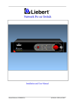
JET #60603 Cooling Fan Switch
(Optional) Fan Switch Harness
INTRODUCTION:
The JET part #60603 coolant fan control is a bimetal disc actuated, stud mounted, SPST, single terminal electrical
switch. The calibrated bimetal disc responds to engine coolant temperature changes to energize an electrically driven
coolant fan motor. The 1/2” bimetal disc snaps from a concave to a convex shape at a predetermined calibration temperature. This snap action occurs in 1/10,000 of a second with the motion directly transferred to the movable arm for
precise snap action cut-in and cut-out. Calibrated bimetal discs are recognized for their inherent reliability and calibration stability. This part has been specifically designed to control electrically driven coolant fan motors on late model GM
automobiles, i.e. Corvette, Camaro, Firebird and Impala, that operate at high ambient tepmeratures. The 60603 lowers
the coolant temperature, thus maximizing engine performance and reducing engine wear.
INSTALLATION PROCEDURES:
Electric Cooling Fan Controlled by a Fan Control Switch
(1.) Drain the cooling system. MAKE SURE THE COOLANT IS COOL! Disconnect the negative (Black)
battery cable from the battery. Locate the factory cooling fan switch. The switch is normally located on the
cylinder head between spark plugs one and three or six and eight. Refer to a General Motors Corvette Service Manual for the switch location.
Call 1-800-782-4356 or go to www.helminc.com to order a GM Corvette Service Manual.
(2.) Unplug the factory cooling fan switch connector. Use a 13/16” deep well socket to remove the factory
cooling fan switch. DO NOT use a spark plug socket. If your vehicle is not equppied with a factory switch,
use a piece of 5/16” square tube to remove the cylinder head water jacket plug.
USE CAUTION WHEN INSTALLING THE SWITCH INTO THE CYLINDER HEAD!
CROSS THREADING WILL CAUSE DAMAGE TO THE HEAD AND OR SWITCH!
(3.) Coat the cooling fan switch threads with sealant to prevent leaks. Use the same 13/16” deep well socket to install the switch. Plug the factory cooling fan switch connector into the switch.
(4.) Reconnect the negative (black) battery cable. Refill the cooling system to the proper level and check for
leaks around the switch. Start the engine and allow the coolant to heat to operating temperature to insure
the fan(s) operate properly.
CAUTION! NEVER PLACE HANDS NEAR COOLING FAN(S) AT ANYTIME.
SEVERE INJURY MAY OCCUR
www.jetchip.com
17491 Apex Circle, Huntington Beach, CA 92647
Tech. Line:(714)848-5515
Fax:(714) 847-6290
ELECTRIC COOLING FANS CONTROLLED BY THE ECM/PCM (COMPUTER)
Refer to steps 1-3 on page #1
(4.) On vehicles that are equipped with ECM/PCM (computer) controlled cooling fan(s), use the JET Fan
Switch Harness. Locate the electric cooling fan relay(s). Refer to GM Service Manual for the relay location.
(5.) Locate the fan signal wire coming from the relay connector. Terminal “F” is normally the signal wire on
newer oval style relays and terminal “B” on the older rectangle style relays. The connector terminal cavities
are identified by letters that are stamped directly on the connector assembly. Always refer to a GM Service
Manual for proper signal wire connector cavity location and wire color. Use a test probe if you are unsure
which lead is the signal wire.
WARNING!! Never connect the Fan Switch Harness leads to a 12 volt power source. Damage to
the harness will occur.
(6.) A. Single Fan Operation:
Attach the “T-Tap” splice connector to the relay signal wire. Attach pink connector by crimping it to
the red or black wire* of the JET Fan Switch Harness. Plug the pink blade connector into the “T-Tap” splice
connector. (Single Fan Operation Only - Cut the extra lead off or tie it up)
B. Dual Fan Operation:
Perform step 6A, then attach the remaining “T-Tap” splice connector to the secondary fan relay signal
wire. Attach the pink connector, by crimping it to the red or black wire* of the Jet Fan Switch Harness. Plug
the pink blade connector into the “T-Tap” splice connector.
*NOTE: The black and red wires are tied together and perform the same function.
When the engine coolant reaches the turn-on point of appoximately 200 degrees F, the fan switch will close
to ground. The ground signal will be sent to the cooling fan relay(s). The cooling fan(s) will turn-on and
remain on until they cool the engine coolant to a turn-off point of approximately 185 degrees F. The fan
switch has apporximatley 15 degree F hystersis with + or - 5 degrees.
Note: Analog and digital temperature gauges are not completely accurate. The turn-on and turn-off temperature may vary slightly from what the vehicle gauge reads. Furthermore, the gauge sensor is located in
a different location than the CFS Switch location. Coolant temperature may vary at different engine coolant
stream locations.
(7.) Reconnect the negative (Black) battery cable. Refill the cooling system to the proper level
and check for leaks around the JET 60603 Cooling Fan Sswitch. Start the engine and allow the coolant to
heat up to operating temperature to insure the fan(s) operate properly.
Caution!! Never place hands or loose clothing near the cooling fan(s) at anytime. Severe injury
may occur.
www.jetchip.com
17491 Apex Circle, Huntington Beach, CA 92647
Tech. Line:(714)848-5515
Fax:(714) 847-6290
Year Model
Main Fan
INSTALLATION CHART
Auxiliary Fan
60603 Install Location Optional Harness Req.
1984 Corvette
Yes (1)
Not Available
Right Side Cylinder Head
1985 Corvette
Yes (2)
Optional (1)
Right Side Cylinder Head
1986 Corvette
Yes (2)
Optional (1)
Left Side Cylinder Head
1987 Corvette
Yes (2)
Optional (1)
Left Side Cylinder Head
1988 Corvette
Yes (2)
Optional (1)
Left Side Cylinder Head
1989 Corvette
Yes (2)
Optional (1)
Left Side Cylinder Head
1990 Corvette
Yes (2)
Optional (1)
Left Side Cylinder Head
1991 Corvette
Yes (2)
Not Available (4)
Left Side Cylinder Head
1992 Corvette
Yes (2)
Not Available (4)
Left Side Cylinder Head
1993 Corvette
Yes (2)
Not Available (4)
Left Side Cylinder Head
1994 Corvette
Yes (2)
Not Available (4)
Left Side Cylinder Head
1995 Corvette
Yes (2)
Not Available (4)
Left Side Cylinder Head
1996 – 2014 Corvette: THIS PRODUCT IS NOT APPLICABLE
(1)
(2)
(3)
(4)
NO
YES
YES
YES
YES
YES
YES
YES
YES
YES
YES
YES
(3)
(3)
(3)
(3)
(3)
(3)
– Controlled by a brass cooling fan switch.
– Controlled by the ECM/PCM (Computer).
- The JET Fan Switch Harness is only required if main cooling fan control is desired.
– This model is equipped with a secondary-cooling fan that is controlled by the ECM/PCM.
1984 Corvette – The main cooling fan is controlled by a brass cooling fan switch identical to the JET 60603.
It’s located on the passenger side cylinder head between spark plugs six and eight. Remove the factory connector by squeezing and pulling it at the same time. Remove the factory switch and replace it with the JET
60603 Switch.
1985 Corvette – The main cooling fan is controlled by the ECM. If euipped with an optional auxiliary cooling
fan (B4P), the fan is controlled by a brass cooling fan switch identical to the JET 60603. It’s located on the
passenger side cylinder head between spark plugs six and eight. The JET 60603 replaces the factory switch.
1986-1989 Corvette - The main cooling fan is controlled by the ECM. If euipped with an optional auxiliary
cooling fan (B4P), the fan is controlled by a brass cooling fan switch identical to the JET 60603. It’s located on the driver side cylinder head between spark plugs one and three. The JET 60603 replaces the factory
switch.
1990-1995 Corvette – The primary and secondary cooling fans are controlled by the ECM/PCM (Computer).
The JET 60603 is installed in the driver side cylinder head between spark plugs one and three. A small 3/8”
water jacket plug must be removed with a piece of 5/16” piece of square tube. The JET 60603 replaces the
plug. The JET Fan Switch harness is required.
www.jetchip.com
17491 Apex Circle, Huntington Beach, CA 92647
Tech. Line:(714)848-5515
Fax:(714) 847-6290
JET #60603 Cooling Fan Switch
JET Cooling Fan Switch Harness (Optional)
www.jetchip.com
17491 Apex Circle, Huntington Beach, CA 92647
Tech. Line:(714)848-5515
Fax:(714) 847-6290