1
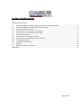
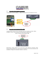
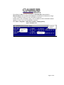
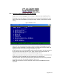
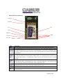
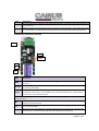
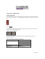
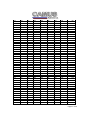
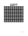
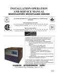
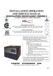
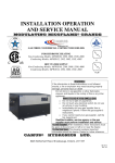
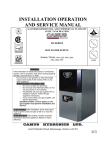
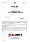
Camus DynaMax and
BMS Protocol
(Modbus, Bacnet IP,
Bacnet MSTP, LONWorks)
Installation Guide
93-0237 Rev. 1.1
6226 Netherhart Road, Mississauga, L5T 1B7, 905-696-7800
DynaMax and BMS Protocols
Table of Contents
1.1 Bacnet/LONWorks Setup through Protocessor Protonode RER/LER .............................................. 3
1.2 Protonode RER and LER showing connection ports ........................................................................ 3
1.3 Record Identification Data ............................................................................................................... 3
1.5 Connection from DynaMax to ProtoNode ....................................................................................... 5
1.6 Connection from ProtoNode RER to BMS........................................................................................ 5
1.7 Power Up the Device ....................................................................................................................... 6
1.8 Install and Run the Utility Software ................................................................................................. 6
1.10 Connect to the ProtoNode using RUI (Ruinet)................................................................................. 8
1.11 Troubleshooting Tips ..................................................................................................................... 10
1.12 ProtoNode Specifications .............................................................................................................. 10
2.1 Modbus .......................................................................................................................................... 11
2.2 Bacnet and Modbus Registers ....................................................................................................... 15
Appendix A ................................................................................................................................................ 27
Page 2 of 34
1.1
Bacnet/LONWorks Setup through Protocessor Protonode RER/LER
Installation steps for the customer
1. Record the information about the unit See Section
2. Set the DIP switches (Bacnet MSTP and LonWorks ONLY)
3. Connect up the Field and Host cable
4. Connect the power
1.2
Protonode RER and LER showing connection ports
Figure 1: Protonode Bacnet RER (left) and Lonworks (LER)
1.3
Record Identification Data
Each ProtoNode has a unique part number located on the underside of the unit. The
number format is FPC-N32-XXX-XXX-XXXX. This number should be recorded as it may be
required for technical support.
Page 3 of 34
1.4
Configure the DIP Switches
1.4.1
Setting the Node/ID Device Instance (Dipswitch A0 – A7)
The DIP switches on the ProtoNode RER and LER allow users to set the Baud Rate,
Node-ID and Mac address on the Field RS-485. Dip switches A0 – A7 can also be used
to set the MAC Address for BACnet MSTP.
Figure 2: A0 – A7 Dip Switches
Please refer to Appendix A for the full range of addresses.
1.4.2
Setting the Baud Rate (Dipswitch B0 –B3)
Setting the serial baud rate to match the baud rate provided by the BMS can be
done through dipswitches B0 – B3.
Table 1: Baud Rate Dip Switch Selection
Baud
110
300
600
1200
2400
4800
9600
19200
20833
28800
38400
57600
76800
115200
B0
Off
Off
On
Off
On
Off
On
Off
On
Off
On
Off
On
Off
B1
Off
On
On
Off
Off
On
On
Off
Off
On
On
Off
Off
On
B2
Off
Off
Off
On
On
On
On
Off
Off
Off
Off
On
On
On
B3
Off
Off
Off
Off
Off
Off
Off
On
On
On
On
On
On
On
Page 4 of 34
1.5
Connection from DynaMax to ProtoNode
The DynaMax terminals J3-MB2 (+, -, GND) are connected to the ProtoNode as shown.
RS 485 (-)
RS 485 (+)
1.6
Connection from ProtoNode RER to BMS
The Bacnet MSTP system can be connected to the 3-pin connector as shown. When
LonWorks is used, a 2-pin connector of the same type is used instead.
Figure 3: Connection from ProtoNode to BMS
Alternatively connect Bacnet IP to the hub via the Ethernet connection when
communicating with Bacnet IP. Ensure that the field device is on the same subnet as the
ProtoNode. Change the ProtoNode IP address if necessary.
Page 5 of 34
1.7
Power Up the Device
Apply power to the device. Ensure that the power supply used complies with the
specifications provided in Appendix B. Ensure that the cable is grounded using the
“Frame-GND” terminal. The ProtoNode is factory set for 24Vac.
Figure 4: Supply Voltage to ProtoNode
1.8
Install and Run the Utility Software
-
1.9
Download the RUINET Utilities from the Protocessor web site (under Utilities
section – Install.zip) www.protocessor.com/downloads/
Run Install.zip and follow the installation instructions
Once installed, the FieldServer Utilities can be located in the Windows Start
menu as a desktop icon
Connect the PC to the ProtoNode via the Ethernet port
Figure 5: Ethernet port location of ProtoNode
-
Disable any wireless Ethernet adapters on the PC/Laptop
Disable firewall and virus protection software
Connect an Ethernet cross-over cable between the PC and ProtoNode and the PC
to the Hub/Switch using a straight cat5 cable
Page 6 of 34
-
-
The Default IP Address of the ProtoNode is 192.168.1.24, Subnet Mask is
255.255.255.0. If the PC and the ProtoNode are on different IP Networks, assign
a static IP Address to the PC on the 192.168.1.0 network.
Double click on the “RUIPING” Utility. If the IP Address of the ProtoNode module
appears on the screen, the ProtoNode is running.
Go to Start > Programs > Field Server Utilities > Ruiping Utility
Figure 6: RUIPING screen
Page 7 of 34
1.10
-
Connect to the ProtoNode using RUI (Ruinet)
Double click on the debugging utility, “RUINET” (Remote User Interface). The
following screen will appear: (if Ruinet does not automatically display the main
menu, select the ProtoNode by typing the 2-digit number to the left of the title
name).
Figure 7: RUINET screen
-
-
-
-
Select “O” for Connection Overview to see the number of messages on each
protocol. If the ProtoNode is communicating correctly with the device then the
display will show Tx and Rx messages without any errors.
If there are errors on the ProtoNode socket communications, edit the points list
in the CSV file until there are no errors. Each time the points the points are
edited, the CSV will need to be re-downloaded using Ruinet.
When communication between the device and the ProtoNode is established the
Field Side of the ProtoNode may be connected to the appropriate
device/software. Ensure that the Field Side parameters on the device/software
are setup as per the “ProtoNode Mapping” document.
Read and write data from each side and make sure the ProtoNode works as
expected.
Page 8 of 34
1.10.1 Changing the Modbus Address
o Change the Modbus Address on the DynaMax
Go to [Configure]
Go to System Identification & Access
Change the Modbus address to the desired setpoint and press [OK]
o Open up the .csv file that is available for download that is available through
the Camus rep support site
Locate cell Node ID located under Nodes and change it to the address
that specified in the Honeywell
Connect 24Vac to the ProtoNode
Connect Ethernet Cable from computer to device
Turn on device
Go to
>
>
Right-click on Local Area Connection > Properties
Highlight
>
Select: Use the following IP address
Click
twice
1.10.2
Changing the IP address
From the main menu, press “I” to enter the Edit IP Address Settings menu
-
Press “1” to modify the IP address of the Ethernet adapter
Type in a new IP address in the format 192.168.2.X and press <Enter>
If necessary, press “2” to and change the netmask
Page 9 of 34
1.11
Troubleshooting Tips
Connection to the ProtoNode
- Confirm that the network cabling is correct
- Confirm that the computer network card is operational and correctly configured
- Confirm that there is an Ethernet adapter installed in the PC’s Device Manager
List, and that it is configured to run the TCP/IP protocol.
- Check that the IP netmask of the PC matches the ProtoNode. The Default IP
Address of the ProtoNode is 192.168.1.24, Subnet Mask is 255.255.255.0
- Go to Start > Run
- Type in “ipconfig”
- The account settings should be displayed
- Ensure that the IP address is 192.168.1.xxx and the netmask
255.255.255.0
- Ensure that the PC and ProtoNode are on the same IP Network, or assign a Static
IP Address to the PC on the 192.168.1.0 network using the Remote User
Interface Utility.
- If Using Windows XP, ensure that the firewall is disabled
- Ensure that all other Ethernet cards active on the PC, especially wireless
adapters are disabled
- Refer to the FieldServer Troubleshooting Guide which can be found at
www/protocessor.com/downloads/ under documentation
1.12
ProtoNode Specifications
Table 2: ProtoNode RER/LER Specifications
Page 10 of 34
BacNet Protocol Gateway
R1 RS485 TX
R1 RS485 RX
PWR
RUN
SYS ERR
COMM ERR
Config ERR
UNUSED
Node Offline
Light
PWR
SYS ERR
COMM
ERR
Config
ERR
Node
Offline
Unused
RX
Description
This is the power light and should show steady green at all times when the FPC-FD2 is powered.
The SYS ERR LED will go on solid 15 seconds after power up. It will turn off after 5 seconds. A steady
red light will indicate there is a system error on the ProtoCessor. If this occurs, immediately report
the related “system error” shown in the error screen of the RUI interface to FieldServer Technologies
for evaluation.
COMM ERR LED will go on solid 15 seconds after power up. It will turn off after 5 seconds. A steady
red light will indicate the communications problem if there is a configured node connected to the
ProtoCessor that is offline. To establish the cause of the error, go to the error screen of the RUI
interface.
Config ERR LED will go on solid 15 seconds after power up. It will turn off after 5 seconds. A steady
amber light will indicate a configuration error exists in the active configuration. See the Error Screen
in the Remote User Interface for a description of the configuration error.
Node Offline LED will go on solid 15 seconds after power up. It will turn off after 5 seconds. If the
Node Offline LED stays on solid, a node offline condition has occurred.
15 seconds after powering up the 4 unused LEDs will turn on solid for 5 seconds, then turn off.
On normal operation of FPC-FD2, the RX LED will flash when a message is received on the field port
of the ProtoCessor.
Page 11 of 34
Light
TX
RUN
Description
On normal operation of FPC-FD2, the TX LED will flash when a message is sent on the field port of
the ProtoCessor
RUN LED will flash 20 seconds after power up, signifying normal operation. The FPC-FD2 will be able
to access RUINET once this LED starts flashing. During the first 20 seconds, the LED should be off
LonWorks Protocol Gateway
LON
PWR
GP105
Rx
Tx
LA
Light
Description
This is the power light and should show steady green at all times when the FFP-F04 is
powered.
Starts flashing about once per second to indicate that the PIC in the ProtoCessor has
LA-PIC A
powered up successfully
Will go on solid within 45 – 60 seconds after power up, signifying normal operation. The
GP105
ProtoCessor will be able to access RUINET shortly after this LED comes on. During the first
45-60 seconds the LED should be dark.
Upon successful operation of GP105 the ProtoCessor will go through diagnostics of the field port
communications.
On normal operation of FFP-F04, the RX LED will flash when a message is received on the
RX
LON port of the ProtoCessor.
On normal operation of FFP-F04,, the TX LED will flash when a message is sent on the LON
TX
port of the ProtoCessor
When the unit is first powered up, before commissioning has occurred, this LED will flash.
LON
Once the unit is commissioned, the LED will stay off during normal operation
PWR
Page 12 of 34
ProtoCarrier 485 (FPC-CD2)
RS-485 Signal LEDs
The RS-485 Signal LEDS are each labeled and correspond to the respective data lines
sent from the ProtoCessor. The following signals are provided. RS-485 TX and RS-485
RX.
2.1
Modbus
The DynaMax is equipped with a standard ICP Modbus port through a 3-pin connector that
interfaces to the following RS-485 signals:
Table 3: Connection Terminals
Signal
Terminal
Data + (a)
1
Data - (b)
2
Serial transmission mode on the Modbus network is RTU mode. Message format has the
following characteristics:
Table 4: DynaMax Data Transmission Specifications
Coding system
8-bit binary
Number of data bits per character 10
1 Start bit
8 data bits, no parity bit
1 stop bit
Bit transfer rate
9600 bps
Physical layer
RS485 (two wire)
Page 13 of 34
Page 14 of 34
2.2
Bacnet and Modbus Registers
Table 5: Modbus and Bacnet IP/MSTP Register Addresses
MN STATE
Modbus
Register
(hex)
0x0000
AI
1
R
MN STATUS
0x0000
AI
2
R
Parameter
Name
Bacnet
Data Type
Bacnet
Object ID
LonWorks
Object ID
Read/Write
Note
0 = Initializing
1 = Initializing
2 = Standby (waiting for demand)
3 = Safety On
4 = Safety Off
5= Pre Purge
6 = Pre Purge 1
7 = Ignit_0
8 = Ignit_1
9 = Burn_0
10 = Post Purge_0
11 = Post Purge_1
12 = Pump_CH_0
13 = Pump_CH_1
14 = Pump_HW_0
15 = Pump_HW_1
16 = Alarm
17 = Error_Check
18 = Burner_Boot
19 = Clear_E2Prom_Error
20 = Store_Block_Error
21 = Wait_A_Second
0 = Standby
10 = Alarm
14 = Block
Page 15 of 34
MN Error
Number
0x0002
AI
3
R
15 = Frost_Protect
16 = CH
17 = Reset_State
18 = Storage
19 = Tap
20 = Pre_Heat
21 = Store_Warm_Hold
Manual Reset Errors
0 = E2Prom_Read_Error
1 = Ignition Error
5 = GV Relay Error
6 = Safety Relay Error
7 = Spare_Lock_Error_1A
8 = Fan_Error
9 = Ram_Error
10 = Wrong_EEProm_Signature
12 = E2Prom_Error
13 = State Error
14 = ROM_Error
16 = 15MS_XRL_Error
17 = Spare_Lock_Error
18 = T_Max_Lock_Error
19 = Stack Error
20 = Flame_Out_Too_Late_Error
21 = Flame_Error_1
22 = 20MS_XRL_Error
23 = 41MS_Error
24 = Too_Many_Flame_Failures
27 = Flag_Byte_Integrity_Error
28 = AD_HI_CPL_Error
Page 16 of 34
29 = AD_LO_CPL_Error
Automatic Reset Errors
31 = Refhi_Too_Lo_Error
32 = Refhi_Too_Hi_Error
33 = Reflo_Too_Lo_Error
34 = Reflo_Too_Lo_Error
36 = Flame_Error_2
40 = Return_Temp_Error
43 = WD_50_Hz_Error
44 = Phase_Error
45 = Net_Freq_Error
46 = Faulty_Earth_Error
47 = WD_Communication_Error
48 = Appliance_Selection_Error
51 = T_Supply_Error
52 = T_Return_Error
55 = T_DHW_Out_Open
56 = T_System_Open
57 = T_Flue_Open
59 = T_Supply_Shorted
60 = T_Return_Shorted
63 = T_DHW_Out_Shorted
54 = T_System_Shorted
65 = T_Flue_Shorted
66 = Blocked_Flue_Error
67 = Flow_Switch_Not_Open_Error
68 = Flow_Switch_Not_Closed_Error
MN System
Test
0x0002
AI
4
R
Page 17 of 34
MN
Flow_Temp
MN
Return_Temp
MN
DHW_Temp
MN
Flue_Temp
MN Flags
MN RAM CH
Setpoint
MN Appliance
Type
MN Control
Config Byte
MN CH Mode
MN DHW
Mode
MN CH
Setpoint
MN DHW
Setpoint
RC Standalone
State
RC Standalone
Status
RC Standalone
Error Number
RC Standalone
System Test
0x0004
AI
5
R
-10 - 117oC
0x0004
AI
6
R
-10 - 117oC
0x0006
AI
7
R
-10 - 117oC
0x0006
AI
8
R
-10 - 117oC
0x0008
0x0008
AI
AI
9
10
R
R
-10 - 117oC
-10 - 117oC
0x000A
AI
11
R
0x000A
AI
12
R
0x000C
0x000C
AI
AI
13
14
R
R
0X000E
AI
15
R
0x000E
AI
16
R
0x0010
AI
17
R
Refer to MN State
0x0010
AI
18
R
Refer to MN Status
0x0012
AI
19
R
Refer to MN Error Number
0x0012
AI
20
R
Page 18 of 34
RC Standalone
Flow Temp
RC Standalone
Return Temp
RC Standalone
DHW Temp
RC Standalone
Flue Temp
RC
CascadeMaster
1 State
RC
CascadeMaster
1 Status
RC
CascadeMaster
1 Error_Num
RC
CascadeMaster
1 System_Test
RC
CascadeMaster
1 Flow Temp
RC
CascadeMaster
1 Return Temp
RC
CascadeMaster
1 DHW Temp
0x0014
AI
21
R
-10 - 117oC
0x0014
AI
22
R
-10 - 117oC
0x0016
AI
23
R
-10 - 117oC
0x0016
AI
24
R
-10 - 117oC
0x0020
AI
25
R
Refer to MN State
0x0020
AI
26
R
Refer to MN Status
0x0022
AI
27
R
Refer to MN Error Number
0x0022
AI
28
R
0x0024
AI
29
R
-10 - 117oC
0x0024
AI
30
R
-10 - 117oC
0x0026
AI
31
R
-10 - 117oC
Page 19 of 34
RC
CascadeMaster
1 Flue Temp
RC
CascadeMaster
2 State
RC
CascadeMaster
2 Status
RC
CascadeMaster
2 Error_Num
RC
CascadeMaster
2 System_Test
RC
CascadeMaster
2 Flow Temp
RC
CascadeMaster
2 Return Temp
RC
CascadeMaster
2 DHW Temp
RC
CascadeMaster
2 Flue Temp
RC
CascadeMaster
3 State
0x0026
AI
32
R
-10 - 117oC
0x0030
AI
33
R
Refer to MN State
0x0030
AI
34
R
Refer to MN Status
0x0032
AI
35
R
Refer to MN Error Number
0x0032
AI
36
R
0x0034
AI
37
R
-10 - 117oC
0x0034
AV
38
R
-10 - 117oC
0x0036
AV
39
R
-10 - 117oC
0x0036
AV
40
R
-10 - 117oC
0x0040
AV
41
R
Refer to MN State
Page 20 of 34
RC
CascadeMaster
3 Status
RC
CascadeMaster
3 Error_Num
RC
CascadeMaster
3 System_Test
RC
CascadeMaster
3 Flow Temp
RC
CascadeMaster
3 Return Temp
RC
CascadeMaster
3 DHW Temp
RC
CascadeMaster
3 Flue Temp
RC
CascadeMaster
4 State
RC
CascadeMaster
4 Status
RC
CascadeMaster
4 Error_Num
0x0040
AV
42
R
Refer to MN Status
0x0042
AV
43
R
Refer to MN Error Number
0x0042
AI
44
R
0x0044
AI
45
R
-10 - 117oC
0x0044
AI
46
R
-10 - 117oC
0x0046
AI
47
R
-10 - 117oC
0x0046
AI
48
R
-10 - 117oC
0x0050
AI
49
R
Refer to MN State
0x0050
AI
50
R
Refer to MN Status
0x0052
AI
51
R
Refer to MN Error Number
Page 21 of 34
RC
CascadeMaster
4 System_Test
RC
CascadeMaster
4 Flow Temp
RC
CascadeMaster
4 Return Temp
RC
CascadeMaster
4 DHW Temp
RC
CascadeMaster
4 Flue Temp
RC
CascadeMaster
5 State
RC
CascadeMaster
5 Status
RC
CascadeMaster
5 Error_Num
RC
CascadeMaster
5 System_Test
RC
CascadeMaster
5 Flow Temp
0x0052
AI
52
R
0x0054
AV
53
R
-10 - 117oC
0x0054
AV
54
R
-10 - 117oC
0x0056
AV
55
R
-10 - 117oC
0x0056
AV
56
R
-10 - 117oC
0x0060
AV
57
R
Refer to MN State
0x0060
AV
58
R
Refer to MN Status
0x0062
AV
59
R
Refer to MN Error Number
0x0062
AV
60
R
0x0064
AV
61
R
-10 - 117oC
Page 22 of 34
RC
CascadeMaster
5 Return Temp
RC
CascadeMaster
5 DHW Temp
RC
CascadeMaster
5 Flue Temp
RC
CascadeMaster
6 State
RC
CascadeMaster
6 Status
RC
CascadeMaster
6 Error_Num
RC
CascadeMaster
6 System_Test
RC
CascadeMaster
6 Flow Temp
RC
CascadeMaster
6 Return Temp
RC
CascadeMaster
6 DHW Temp
0x0064
AV
62
R
-10 - 117oC
0x0066
AV
63
R
-10 - 117oC
0x0066
AV
64
R
-10 - 117oC
0x0070
AV
65
R
Refer to MN State
0x0070
AV
66
R
Refer to MN Status
0x0072
AV
67
R
Refer to MN Error Number
0x0072
AV
68
R
0x0074
AV
69
R
-10 - 117oC
0x0074
AV
70
R
-10 - 117oC
0x0076
AV
71
R
-10 - 117oC
Page 23 of 34
RC
CascadeMaster
6 Flue Temp
RC
CascadeMaster
7 State
RC
CascadeMaster
7 Status
RC
CascadeMaster
7 Error_Num
RC
CascadeMaster
7 System_Test
RC
CascadeMaster
7 Flow Temp
RC
CascadeMaster
7 Return Temp
RC
CascadeMaster
7 DHW Temp
RC
CascadeMaster
7 Flue Temp
RC
CascadeMaster
8 State
0x0076
AV
72
R
-10 - 117oC
0x0080
AV
73
R
Refer to MN State
0x0080
AV
74
R
Refer to MN Status
0x0082
AV
75
R
Refer to MN Error Number
0x0082
AV
76
R
0x0084
AI
77
R
-10 - 117oC
0x0084
AV
78
R/W
-10 - 117oC
0x0086
AV
79
R/W
-10 - 117oC
0x0086
AI
80
R
-10 - 117oC
0x0090
AI
81
R
Refer to MN State
Page 24 of 34
RC
CascadeMaster
8 Status
RC
CascadeMaster
8 Error_Num
RC
CascadeMaster
8 System_Test
RC
CascadeMaster
8 Flow Temp
RC
CascadeMaster
8 Return Temp
RC
CascadeMaster
8 DHW Temp
RC
CascadeMaster
8 Flue Temp
MN Reset Bit
CH Setpoint
Write Enable
DHW Setpoint
Write Enable
MN CH
Setpoint
MN DHW
Setpoint
0x0090
AI
82
R
Refer to MN Status
0x0092
AI
83
R
Refer to MN Error Number
0x0092
AI
84
R
0x0094
AI
85
R
-10 - 117oC
0x0094
AI
86
R
-10 - 117oC
0x0096
AI
87
R
-10 - 117oC
0x0096
AI
88
R
-10 - 117oC
0x001A
---
BV
BV
1
2
R/W
R/W
---
BV
3
R/W
0x001A
0x001E
0x001A
0x001E
AV
1
R/W
AV
2
R/W
A value of 1 must be written before
adjusting the MN CH Setpoint
A value of 1 must be written before
adjusting the MN DHW Setpoint
Page 25 of 34
MODBUS Write CH Setpoint
1) Issue a Modbus write single holding register command writing 0x0002 to the Reset &
R/W control register located at 0x001A to switch from CH set point reading to writing
2) Calculate the scaled set point = (((x-32)/1.8)+10)*2*256
3) Issue a Modbus write single holding register command writing the scaled calculated set
point to the 0x001E holding register
MODBUS Write DHW Setpoint
1) Issue a Modbus write single holding register command writing 0x001 to the Reset &
R/W Control register located at 0x001A to switch from DHW set point reading to writing
2) Calculate the scaled set point = ((x-32)/1.8)+10)*2
3) Issue a Modbus write single holding register command writing the scaled and calculated
set point to the 0x001E holding register
•
NOTE
Be advised that whenever the MN control is reset, it will revert back to the setpoints stored
in the E2Prom. After every MN reset (automatic, through Modbus, via the IF External Reset
Input or via the RC reset button) the Modbus controller must make sure that the error
condition has been resolved (ERROR_NUMBER = 0xFF) and then re-write the desired
setpoints through Modbus
•
If the Reset & R/W control register bit of a setpoint is set, the setpoint in the IF is
communicated with the MN as long as it differs from the setpoint in the DynaMax Ignition
Module. If the setpoint is then changed by means of the Display or LabVision it will again be
different from the setpoint in the IF and thus, again be overwritten by the setpoint in the IF.
As long as the Reset & R/W control register bit of the setpoint is set the IF overrules all other
setpoint settings. Clear the bit in the Reset & R/W Control register to re-enable setting of the
setpoint by RC or LabVision
•
When no Modbus communication (reading or writing) is sensed for more than 4.25 seconds
the R/W control register bits will be reset. The R/W control register bits will be reset. The
R/W control register bits will also be reset when undefined bits (ie. other than bits 0 and 1)
are set.
•
In a cascade system only the setpoints of the MN board connected directly to the IF board
can be controlled.
Page 26 of 34
Appendix A
A7
A6
A5
A4
A3
A2
A1
A0
Address
Off
Off
Off
Off
Off
Off
Off
Off
Off
Off
Off
Off
Off
Off
Off
Off
Off
Off
Off
Off
Off
Off
Off
Off
Off
Off
Off
Off
Off
Off
Off
Off
Off
Off
Off
Off
Off
Off
Off
Off
Off
Off
Off
Off
Off
Off
Off
Off
Off
Off
Off
Off
Off
Off
Off
Off
Off
Off
Off
Off
Off
Off
Off
Off
Off
Off
Off
Off
Off
Off
Off
Off
Off
Off
Off
Off
Off
Off
Off
Off
Off
Off
Off
Off
Off
Off
Off
Off
Off
Off
Off
Off
Off
Off
Off
Off
Off
Off
Off
Off
Off
Off
Off
Off
Off
Off
Off
Off
Off
Off
Off
Off
Off
Off
Off
Off
Off
Off
On
On
On
On
On
On
On
On
On
On
On
Off
Off
Off
Off
Off
Off
Off
Off
Off
Off
Off
Off
Off
Off
Off
Off
On
On
On
On
On
On
On
On
On
On
On
On
On
On
On
On
Off
Off
Off
Off
Off
Off
Off
Off
Off
Off
Off
Off
Off
Off
Off
Off
Off
Off
Off
On
On
On
On
On
On
On
On
Off
Off
Off
Off
Off
Off
Off
Off
On
On
On
On
On
On
On
On
Off
Off
Off
Off
Off
Off
Off
Off
On
On
On
Off
Off
Off
Off
On
On
On
On
Off
Off
Off
Off
On
On
On
On
Off
Off
Off
Off
On
On
On
On
Off
Off
Off
Off
On
On
On
On
Off
Off
Off
Off
On
On
On
On
Off
Off
Off
Off
Off
On
On
Off
Off
On
On
Off
Off
On
On
Off
Off
On
On
Off
Off
On
On
Off
Off
On
On
Off
Off
On
On
Off
Off
On
On
Off
Off
On
On
Off
Off
On
On
Off
Off
On
Off
On
Off
On
Off
On
Off
On
Off
On
Off
On
Off
On
Off
On
Off
On
Off
On
Off
On
Off
On
Off
On
Off
On
Off
On
Off
On
Off
On
Off
On
Off
On
Off
On
Off
On
Off
0
1
2
3
4
5
6
7
8
9
10
11
12
13
14
15
16
17
18
19
20
21
22
23
24
25
26
27
28
29
30
31
32
33
34
35
36
37
38
39
40
41
42
Page 27 of 34
Off
Off
Off
Off
Off
Off
Off
Off
Off
Off
Off
Off
Off
Off
Off
Off
Off
Off
Off
Off
Off
Off
Off
Off
Off
Off
Off
Off
Off
Off
Off
Off
Off
Off
Off
Off
Off
Off
Off
Off
Off
Off
Off
Off
Off
Off
Off
Off
Off
Off
Off
Off
Off
Off
Off
Off
Off
Off
Off
Off
Off
Off
Off
Off
Off
Off
Off
On
On
On
On
On
On
On
On
On
On
On
On
On
On
On
On
On
On
On
On
On
On
On
On
On
On
On
On
On
On
On
On
On
On
On
On
On
On
On
On
On
On
On
On
On
On
Off
Off
Off
Off
Off
Off
Off
Off
Off
Off
Off
Off
Off
Off
Off
Off
Off
Off
Off
Off
Off
Off
Off
Off
Off
Off
Off
Off
Off
Off
On
On
On
On
On
On
On
On
On
On
On
On
On
On
On
On
Off
Off
Off
Off
Off
Off
Off
Off
Off
Off
Off
Off
Off
Off
Off
Off
On
On
On
On
On
On
On
On
On
On
On
On
On
On
Off
Off
Off
Off
Off
Off
Off
Off
On
On
On
On
On
On
On
On
Off
Off
Off
Off
Off
Off
Off
Off
On
On
On
On
On
On
On
On
Off
Off
Off
Off
Off
Off
Off
Off
On
Off
On
On
On
On
Off
Off
Off
Off
On
On
On
On
Off
Off
Off
Off
On
On
On
On
Off
Off
Off
Off
On
On
On
On
Off
Off
Off
Off
On
On
On
On
Off
Off
Off
Off
On
On
On
On
Off
On
Off
Off
On
On
Off
Off
On
On
Off
Off
On
On
Off
Off
On
On
Off
Off
On
On
Off
Off
On
On
Off
Off
On
On
Off
Off
On
On
Off
Off
On
On
Off
Off
On
On
Off
Off
On
On
Off
On
Off
On
Off
On
Off
On
Off
On
Off
On
Off
On
Off
On
Off
On
Off
On
Off
On
Off
On
Off
On
Off
On
Off
On
Off
On
Off
On
Off
On
Off
On
Off
On
Off
On
Off
On
Off
On
Off
43
44
45
46
47
48
49
50
51
52
53
54
55
56
57
58
59
60
61
62
63
64
65
66
67
68
69
70
71
72
73
74
75
76
77
78
79
80
81
82
83
84
85
86
87
88
Page 28 of 34
Off
Off
Off
Off
Off
Off
Off
Off
Off
Off
Off
Off
Off
Off
Off
Off
Off
Off
Off
Off
Off
Off
Off
Off
Off
Off
Off
Off
Off
Off
Off
Off
Off
Off
Off
Off
Off
Off
Off
On
On
On
On
On
On
On
On
On
On
On
On
On
On
On
On
On
On
On
On
On
On
On
On
On
On
On
On
On
On
On
On
On
On
On
On
On
On
On
On
On
On
On
On
On
On
Off
Off
Off
Off
Off
Off
Off
Off
Off
Off
Off
Off
Off
Off
On
On
On
On
On
On
On
On
On
On
On
On
On
On
On
On
On
On
On
On
On
On
On
On
On
On
On
On
On
On
On
On
Off
Off
Off
Off
Off
Off
Off
On
On
On
On
On
On
On
Off
Off
Off
Off
Off
Off
Off
Off
Off
Off
Off
Off
Off
Off
Off
Off
On
On
On
On
On
On
On
On
On
On
On
On
On
On
On
On
Off
Off
Off
Off
Off
Off
Off
On
On
On
On
On
On
On
Off
Off
Off
Off
Off
Off
Off
Off
On
On
On
On
On
On
On
On
Off
Off
Off
Off
Off
Off
Off
Off
On
On
On
On
On
On
On
On
Off
Off
Off
Off
Off
Off
Off
Off
Off
Off
On
On
On
On
Off
Off
Off
Off
On
On
On
On
Off
Off
Off
Off
On
On
On
On
Off
Off
Off
Off
On
On
On
On
Off
Off
Off
Off
On
On
On
On
Off
Off
Off
Off
On
On
On
Off
On
On
Off
Off
On
On
Off
Off
On
On
Off
Off
On
On
Off
Off
On
On
Off
Off
On
On
Off
Off
On
On
Off
Off
On
On
Off
Off
On
On
Off
Off
On
On
Off
Off
On
On
Off
Off
On
On
Off
On
Off
On
Off
On
Off
On
Off
On
Off
On
Off
On
Off
On
Off
On
Off
On
Off
On
Off
On
Off
On
Off
On
Off
On
Off
On
Off
On
Off
On
Off
On
Off
On
Off
On
Off
On
Off
89
90
91
92
93
94
95
96
97
98
99
100
101
102
103
104
105
106
107
108
109
110
111
112
113
114
115
116
117
118
119
120
121
122
123
124
125
126
127
128
129
130
131
132
133
134
Page 29 of 34
On
On
On
On
On
On
On
On
On
On
On
On
On
On
On
On
On
On
On
On
On
On
On
On
On
On
On
On
On
On
On
On
On
On
On
On
On
On
On
On
On
On
On
On
On
On
Off
Off
Off
Off
Off
Off
Off
Off
Off
Off
Off
Off
Off
Off
Off
Off
Off
Off
Off
Off
Off
Off
Off
Off
Off
Off
Off
Off
Off
Off
Off
Off
Off
Off
Off
Off
Off
Off
Off
Off
Off
Off
Off
Off
Off
Off
Off
Off
Off
Off
Off
Off
Off
Off
Off
Off
Off
Off
Off
Off
Off
Off
Off
Off
Off
Off
Off
Off
Off
Off
Off
On
On
On
On
On
On
On
On
On
On
On
On
On
On
On
On
On
On
On
On
On
Off
Off
Off
Off
Off
Off
Off
Off
Off
On
On
On
On
On
On
On
On
On
On
On
On
On
On
On
On
Off
Off
Off
Off
Off
Off
Off
Off
Off
Off
Off
Off
Off
Off
Off
Off
On
On
On
On
On
Off
On
On
On
On
On
On
On
On
Off
Off
Off
Off
Off
Off
Off
Off
On
On
On
On
On
On
On
On
Off
Off
Off
Off
Off
Off
Off
Off
On
On
On
On
On
On
On
On
Off
Off
Off
Off
Off
On
Off
Off
Off
Off
On
On
On
On
Off
Off
Off
Off
On
On
On
On
Off
Off
Off
Off
On
On
On
On
Off
Off
Off
Off
On
On
On
On
Off
Off
Off
Off
On
On
On
On
Off
Off
Off
Off
On
On
Off
Off
On
On
Off
Off
On
On
Off
Off
On
On
Off
Off
On
On
Off
Off
On
On
Off
Off
On
On
Off
Off
On
On
Off
Off
On
On
Off
Off
On
On
Off
Off
On
On
Off
Off
On
On
Off
On
Off
On
Off
On
Off
On
Off
On
Off
On
Off
On
Off
On
Off
On
Off
On
Off
On
Off
On
Off
On
Off
On
Off
On
Off
On
Off
On
Off
On
Off
On
Off
On
Off
On
Off
On
Off
On
Off
135
136
137
138
139
140
141
142
143
144
145
146
147
148
149
150
151
152
153
154
155
156
157
158
159
160
161
162
163
164
165
166
167
168
169
170
171
172
173
174
175
176
177
178
179
180
Page 30 of 34
On
On
On
On
On
On
On
On
On
On
On
On
On
On
On
On
On
On
On
On
On
On
On
On
On
On
On
On
On
On
On
On
On
On
On
On
On
On
On
On
On
On
On
On
On
On
Off
Off
Off
Off
Off
Off
Off
Off
Off
Off
Off
On
On
On
On
On
On
On
On
On
On
On
On
On
On
On
On
On
On
On
On
On
On
On
On
On
On
On
On
On
On
On
On
On
On
On
On
On
On
On
On
On
On
On
On
On
On
Off
Off
Off
Off
Off
Off
Off
Off
Off
Off
Off
Off
Off
Off
Off
Off
Off
Off
Off
Off
Off
Off
Off
Off
Off
Off
Off
Off
Off
Off
Off
Off
On
On
On
On
On
On
On
On
On
On
On
On
On
On
Off
Off
Off
Off
Off
Off
Off
Off
Off
Off
Off
Off
Off
Off
Off
Off
On
On
On
On
On
On
On
On
On
On
On
On
On
On
On
On
Off
Off
Off
Off
Off
Off
On
On
On
On
On
On
On
On
Off
Off
Off
Off
Off
Off
Off
Off
On
On
On
On
On
On
On
On
Off
Off
Off
Off
Off
Off
Off
Off
On
On
On
On
On
On
On
On
Off
Off
Off
On
On
On
Off
Off
Off
Off
On
On
On
On
Off
Off
Off
Off
On
On
On
On
Off
Off
Off
Off
On
On
On
On
Off
Off
Off
Off
On
On
On
On
Off
Off
Off
Off
On
On
On
On
Off
Off
Off
Off
On
On
Off
Off
On
On
Off
Off
On
On
Off
Off
On
On
Off
Off
On
On
Off
Off
On
On
Off
Off
On
On
Off
Off
On
On
Off
Off
On
On
Off
Off
On
On
Off
Off
On
On
Off
Off
On
On
Off
On
Off
On
Off
On
Off
On
Off
On
Off
On
Off
On
Off
On
Off
On
Off
On
Off
On
Off
On
Off
On
Off
On
Off
On
Off
On
Off
On
Off
On
Off
On
Off
On
Off
On
Off
On
Off
181
182
183
184
185
186
187
188
189
190
191
192
193
194
195
196
197
198
199
200
201
202
203
204
205
206
207
208
209
210
211
212
213
214
215
216
217
218
219
220
221
222
223
224
225
226
Page 31 of 34
On
On
On
On
On
On
On
On
On
On
On
On
On
On
On
On
On
On
On
On
On
On
On
On
On
On
On
On
On
On
On
On
On
On
On
On
On
On
On
On
On
On
On
On
On
On
On
On
On
On
On
On
On
On
On
On
On
On
On
On
On
On
On
On
On
On
On
On
On
On
On
On
On
On
On
On
On
On
On
On
On
On
On
On
On
On
On
Off
Off
Off
Off
Off
Off
Off
Off
Off
Off
Off
Off
Off
On
On
On
On
On
On
On
On
On
On
On
On
On
On
On
On
Off
Off
Off
Off
Off
On
On
On
On
On
On
On
On
Off
Off
Off
Off
Off
Off
Off
Off
On
On
On
On
On
On
On
On
Off
On
On
On
On
Off
Off
Off
Off
On
On
On
On
Off
Off
Off
Off
On
On
On
On
Off
Off
Off
Off
On
On
On
On
On
Off
Off
On
On
Off
Off
On
On
Off
Off
On
On
Off
Off
On
On
Off
Off
On
On
Off
Off
On
On
Off
Off
On
On
On
Off
On
Off
On
Off
On
Off
On
Off
On
Off
On
Off
On
Off
On
Off
On
Off
On
Off
On
Off
On
Off
On
Off
On
227
228
229
230
231
232
233
234
235
236
237
238
239
240
241
242
243
244
245
246
247
248
249
250
251
252
253
254
255
Page 32 of 34
Page 33 of 34
J5
J2
2
3
4
+
-
10 9 8 7 6
5 4 3 2 1
1
4
2
3
J7
1
848IF
INTERFACE MODULE
NOTE:
1) Alarm contact must be powered externally with 24Vac or 115Vac.
2) Alarm can drive an external device such as a lamp, buzzer, PLC or Buidling Management System (BMS)
EXTERNAL
RESET
0-10Vdc
EXTERNAL
INPUT
ALARM (24 VAC / 115 VAC)
3
6
1
5
J4
2
2 1
J1
4
3
DATA -
DATA +
MODBUS
COMM.
L
KC
DISPLAY
GROUND
N
May-05-09
FIELD SUPPLY
115V 60Hz
C
99-0134
1
DynaMax, Interface Module (848IF),
Electrical Connection Diagram
1
00
Note: 1) If any of the original wire as supplied with the
appliance must be replaced, it must be replaced with
wiring having a temperature rating of at least 105C
CONNECTION
DIAGRAM
---- FIELD SUPPLIED
····· OPTIONAL EQUIPMENT
BK - BLACK
BL- BLUE
BR - BROWN
G - GREEN
O - ORANGE
P - PURPLE
W - WHITE
Y - YELLOW
R - RED
NOTES
Page 34 of 34