1
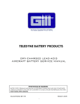
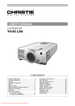
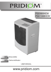
TELEDYNE BATTERY PRODUCTS
MAINTENANCE MANUAL
For
7638-38HT
PROPOSITION 65 WARNING
BATTERY POSTS, TERMINALS AND RELATED ACCESSORIES CONTAIN LEAD AND LEAD COMPOUNDS,
CHEMICALS KNOWN TO THE STATE OF CALIFORNIA TO CAUSE CANCER AND REPRODUCTIVE HARM.
WASH HANDS AFTER HANDLING.
Document Number: Q01-2002
Revision : E 12-21-14
i
Receipt and use of this technical document by any receiving party is subject to compliance with all decrees, statutes, rules and regulations of
the United States Government and of the Governments of the countries in which Teledyne Battery Products and the receiving party are doing
business at the time of receipt by the receiving party in effect, or which may be in effect hereafter, which govern exports or otherwise
pertains to export controls, including without limitation, the Export Administration Regulations and the International Traffic in Arms
Regulations.
WARNING
THE SAFETY INSTRUCTIONS/PRECAUTIONS POSTED IN VARIOUS SECTIONS WITHIN THIS MANUAL MUST
BE STRICTLY FOLLOWED.
ALWAYS WEAR SAFETY GLASSES AND ACID-RESISTANT GLOVES WHENEVER HANDLING BATTERIES
ELECTROLYTE CONTAINS SULFURIC ACID, WHICH CAN PERMANENTLY DAMAGE EYES AND CAUSE
SEVERE BURNS TO EXPOSED SKIN.
FOR LIMITATIONS, PROCEDURES AND PERFORMANCE INFORMATION NOT CONTAINED IN THIS SUPPLEMENT CONSULT THE
BASIC PILOTS OPERATING HANDBOOK, AIRPLANE FLIGHT MANUAL, THE SPECIFIC STC OR THE BATTERY CONTINUOUS
AIRWORTHINESS INSTRUCTIONS FOR THE APPLICATION.
THIS SERVICE MANUAL SHOULD NOT BE CONSTRUED AS THE FINAL AUTHORITY IN MAINTAINING YOUR SPECIFIC BATTERY.
PLEASE CONSULT WITH TELEDYNE TECHNICAL SUPPORT FOR FURTHER INFORMATION.
ii
MAINTENANCE MANUAL
Section
CONTENTS
1.
REVISION PAGE ………………………………………………………….
3.
LT VALVE-REGULATED LEAD-ACID BATTERIES
2.
SCOPE
1
………………………………………………………….
3.1
………………………………………….
4. SERVICE INSTRUCTIONS
………………………………………….
3.2
Specifications, Definition of Terms
Shipment of Batteries
………………………………….
4.3
Storage Requirements
………………………………….
Inspection for Shipping Damage
4.4
5. CHARGING
Initial Inspection
Overview
5.3
Constant-Current
Constant-Voltage
Initial Charging
5.4
5.5
Overcharging
6. ROUTINE MAINTENANCE
6.1
4
6
6
………………….
6
7
………………………………….
8
9
………………………………………….
………………………………….
9
9
………………………………….
11
………………………………………….
12
………………………………………….
………………………………………….
11
13
Inspection/Service Period
………………………….
- Capacity Testing
………………………….
13
Inspection of Heater Circuit
………………………….
15
6.2
Continued Airworthiness Requirement
6.3
Inspection of Connectors
6.5
Recovery from Deep-Discharge
6.4
3
………………………………………………………….
5.1
5.2
3
………………….
4.1
4.2
2
………………….
Description
7. UNSCHEDULED REMOVAL
8. TRANSPORTATION
9. RECYCLING
10. GLOSSARY
………………………….
………………………………………………….
………………………………………………………….
………………………………………………………….
………………………….
12. APPENDIX B FREEZE SPRAY SPECIFICATIONS
Revision: E
………………….
………………………………………….
11. APPENDIX A LT VRLA Battery Capacities
Q01-2002
Page
iii
………………….
13
14
17
18
19
20
22
23
24
Teledyne Battery Products
Section 1
MAINTENANCE MANUAL
REVISIONS
NC
A
B
Description of Change
New document
Revised Table 1 to support recharging
severely discharged batteries
Revised Table 1 to add capacity test
statement
Approved By
Date
JMR
9-30-09
JMR
4-7-10
JMR
5-4-10
JMR
3-4-12
Revised performance requirement in
C
section 6.2.4 from 80% to 85%; revised
conditioning during capacity testing,
section 6
D
Revised section 6.2
JMR
9-4-12
E
Revised section 6.4
JMR
12-21-14
Q01-2002
Rev E 12-20-14
Page 1 of 25
Premium LT Valve Regulated Lead Acid Aircraft Batteries By TELEDYNE BATTERY PRODUCTS
Revision
Section 2
MAINTENANCE MANUAL
SCOPE
Series LT Valve-Regulated Lead-Acid (LT VRLA) Aircraft Batteries manufactured part number
7638-38HT
This manual has been written for the purpose of guidance only; consult Teledyne Battery
Products Technical Support for further information.
Q01-2002
Rev E 12-20-14
Page 2 of 25
Premium LT Valve Regulated Lead Acid Aircraft Batteries By TELEDYNE BATTERY PRODUCTS
This manual provides Maintenance Procedures for Teledyne Battery Products’ (TBP) 7000
Section 3
MAINTENANCE MANUAL
VALVE-REGULATED LEAD-ACID BATTERIES
3.1.1. The 7000 series LT valve-regulated lead-acid (VRLA) batteries are designed
with an optimum lead alloy with tin to provide the best possible electrode
characteristics necessary for performance. These VRLA batteries contain
electrolyte absorbed in glass-mat separators, with no free electrolyte and are
sometimes referred to as “sealed” or “recombinant-gas” batteries.
WARNING
ALL VRLA batteries contain sulfuric acid, which is highly corrosive and which can cause
serious physical injury if it comes in contact with skin or if inhaled. It can also cause
serious eye injury or blindness if it comes into contact with the eyes.
Caution must be exercised to avoid damage to the exterior case which could allow the
contents to escape or come in physical contact with external materials or personnel.
If a battery case is found to be damaged, handle the battery with care and avoid
contact with the skin. Inspect all areas adjacent to the battery for evidence of
corrosion.
3.1.2. TBP valve-regulated lead-acid batteries have vent caps (with valves enclosed)
that are sealed in place and cannot be accessed for maintenance. At no time
must these vent caps be removed.
WARNING
During normal operation, the batteries will vent very small amounts of gases that must
be vented away from the battery and aircraft. The venting mechanisms consist of
nozzles (in the battery cover) and vent tubes that are designed to exhaust the battery
compartment. Ensure that the vent tubes are not restricted or disabled in any way.
3.1.3. The electrolyte is contained in an absorptive glass-mat (AGM) separator that
retains and immobilizes the electrolyte. These batteries can be operated in any
orientation without spilling electrolyte.
3.1.4. The battery consists of twelve cells connected in series internally, making up a
24V battery. These cells are not replaceable.
Q01-2002
Rev E 12-20-14
Page 3 of 25
Premium LT Valve Regulated Lead Acid Aircraft Batteries By TELEDYNE BATTERY PRODUCTS
3.1 DESCRIPTION
MAINTENANCE MANUAL
3.1.5. Each cell is constructed of premium grade LT electrodes (plates) that are
electrically isolated by AGM separators.
SPECIFICATIONS
3.2.1
TBP battery ratings are defined by a series of specifications:
3.2.1.1
The One-Hour Rate
This is the rate of discharge a battery can endure for one hour
with the battery voltage at or above 1.67 volts per cell, or 20 volts
for a 24 volt lead-acid battery, or 10 volts for a 12 volt lead-acid
battery.
The One-Hour Capacity, measured in Ampere Hours or Ah, is the
product of the discharge rate and time (in hours) to the specified
end voltage.
3.2.1.2
The Emergency Rate
This is the rate of discharge a battery can endure for thirty
minutes with the battery voltage at or above 1.67 volts per cell, or
20 volts for a 24 volt lead-acid battery, or 10 volts for a 12 volt
lead-acid battery.
The Emergency Rate is the total essential load, measured in
amperes, required to support the essential bus for thirty minutes.
3.2.1.3
Ipp: This is the peak current delivered at 0.3 seconds into a 15
second controlled discharge at a constant terminal voltage of half
the nominal battery voltage.
Ipr: This is the discharge current at the conclusion of a 15 second
controlled discharge at a constant terminal voltage of half the
nominal battery voltage.
3.2.2
State of charge using voltage measurements should be used as a guide only.
Figure 1 indicates the relationship between Battery Open-Circuit Voltage (OCV)
and % State-of-Charge (SOC). Please note that state-of-charge is not the same
as available capacity (see GLOSSARY).
Q01-2002
Rev E 12-20-14
Page 4 of 25
Premium LT Valve Regulated Lead Acid Aircraft Batteries By TELEDYNE BATTERY PRODUCTS
3.2
MAINTENANCE MANUAL
Figure 1
26.8
Terminal Voltage (V)
26.3
25.8
25.3
24.8
24.3
0
10
20
30
40
50
60
70
80
90
100
State of Charge (%)
3.2.3. All valve-regulated batteries operate best in controlled temperatures. Excessive
excursions above 1000F can shorten the life of lead-acid batteries. The
optimum operating temperature is around 800F.
Available capacity declines as the temperature drops. This decline is primarily
related to the state of the electrolyte and easily recoverable once the battery
has warmed up sufficiently.
Q01-2002
Rev E 12-20-14
Page 5 of 25
Premium LT Valve Regulated Lead Acid Aircraft Batteries By TELEDYNE BATTERY PRODUCTS
Open Circuit Voltage
24V LT Valve-Regulated Lead-Acid Battery
Section 4
MAINTENANCE MANUAL
SERVICE INSTRUCTIONS
SHIPMENT OF BATTERIES
4.1.1
The batteries are shipped conditioned and fully charged.
4.1.2
Each battery is identified with a unique serial number label and manufacturing
date marked with indelible ink on the right side of the battery (side adjacent to
the positive terminal, with the terminals facing forward). Please use this
manufacturing date for future reference.
4.2
INSPECTION FOR SHIPPING DAMAGE
4.2.1
Upon receipt, the packages must be examined for any shipping damage before
they are placed in storage or use. If any damage is noted, contact the shipping
company immediately.
4.2.2
4.3
Type verification can be performed by checking the serial number label on the
packaging against the accompanying Certificate of Compliance.
STORAGE REQUIREMENTS
4.3.1
Teledyne’s 7000 series LT valve-regulated lead-acid batteries can be stored
between -200F and +1100F (store ideally at 800F). Storage at temperatures
other than these, can lead to permanent damage.
Storage temperatures will determine inspection requirements.
4.3.2
Teledyne’s 7000 series valve-regulated lead-acid batteries have a maximum of
24 months of inspection-free storage life, IF stored at temperatures between
400F to 800F.
Batteries maintained at lower temperatures should be reviewed in this category
as well.
4.3.3
Review figure 2 to determine the shelf life at various temperatures indicated.
The 7000 series batteries can be stored for the number of days at the
temperature indicated in Figure 2 without any damage.
Q01-2002
Rev E 12-20-14
Page 6 of 25
Premium LT Valve Regulated Lead Acid Aircraft Batteries By TELEDYNE BATTERY PRODUCTS
4.1
MAINTENANCE MANUAL
Figure 2
Storage Time - Days
10,000
1,000
100
10
150C (590F)
200C (680F)
250C (770F)
300C (860F)
350C(950F)
Storage Temperature
4.3.4
If stored between 950F (350C) to 1100F (430C), the battery must be inspected on
a monthly basis. It is not recommended to store any VRLA batteries at these
temperatures for excessive periods of time (maximum 3 months storage).
Prolonged storage at high temperatures (over 1100F) will reduce battery life.
4.3.5
All batteries returned from service after initial use must be stored fully charged.
The storage start date and battery voltage must be logged on the outer
package or marked on the battery.
4.3.6
Long term storage at low temperatures (around 00F) will not detrimentally
affect the life of the battery, provided the battery is at a reasonably high state
of charge (over 80%) before placing in storage.
4.3.7
Q01-2002
Please call TBP technical support if there are any questions regarding shelf life
and recharge periods.
Rev E 12-20-14
Page 7 of 25
Premium LT Valve Regulated Lead Acid Aircraft Batteries By TELEDYNE BATTERY PRODUCTS
Shelf Life for 7000 Series LT VRLA Batteries
In Days to 30% State of Charge
MAINTENANCE MANUAL
4.4
INITIAL INSPECTION
Visually inspect the battery to ensure there is no damage. Remove the
protective cap over the terminal pins and ensure that the pins are clean and
there is no corrosion. The pins have been installed with the correct torque at
the factory and do not require any re-seating. Call TBP Technical Support if you
find any discrepancy.
4.4.2
DO NOT remove the lid. The vents are sealed in the cover and cannot be
4.4.3
Inspect the open circuit voltage. Typical practice should be to recharge the
removed for maintenance.
battery at constant potential before placing into service. Review section 5 for all
charging instructions.
For basic charging, constant-potential is the preferred charging method. Deep-
discharge recovery will usually require application of Constant-Current and/or
Constant-Potential charging (see 6.4). Please consult with technical support at
Teledyne before attempting recovery from prolonged deep-discharge.
WARNING
ALL VRLA batteries contain sulfuric acid, which is highly corrosive and which can cause
serious physical injury if it comes in contact with skin or if inhaled. It can also cause
serious eye injury or blindness if it comes into contact with the eyes.
Caution must be exercised to avoid damage to the exterior case which could allow the
contents to escape or come in physical contact with external materials or personnel.
If a battery case is found to be damaged, handle the battery with care and avoid
contact with the skin. Inspect all areas adjacent to the battery for evidence of
corrosion.
4.4.4
Charging should be terminated when the charge current drops to less than 0.5
ampere (may takes up to 15 hours depending on the state-of-charge of the
battery).
Q01-2002
Rev E 12-20-14
Page 8 of 25
Premium LT Valve Regulated Lead Acid Aircraft Batteries By TELEDYNE BATTERY PRODUCTS
4.4.1
Section 5
MAINTENANCE MANUAL
CHARGING
Charging should be conducted in a well-ventilated area at ambient conditions ranging from
650F to 800F.
5.1
OVERVIEW
5.1.1
Please review the charging method (constant-current or constant-voltage)
5.1.2
Correct charging is very important and will affect the overall life of the battery.
before commencing. The preferred method is constant-voltage.
The charging process is not 100% efficient due to losses resulting from internal
resistance and will typically require 2% to 6% more recharge than the amount of
capacity removed during discharge.
5.1.3
Overcharging generally occurs when either constant-current charging is used
without adequate control of total time on-charge or the voltage limit in
constant-voltage charge is higher than the recommended range (see 5.2.4).
Overcharging a battery will corrode the positive grids and break-down the
water component in the electrolyte to hydrogen and oxygen (electrolysis). This
is quite detrimental to the life of VRLA batteries since the water cannot be
replaced.
5.2
STANDARD CONSTANT-POTENTIAL (VOLTAGE; CP/CV)
5.2.1
These chargers are generally designed to provide a constant voltage source,
with selectable initial current rates. Model variants provide selectable charge
voltage and initial charge rates. Higher output current will reduce recharge
time.
5.2.2
Because the current in any circuit is directly proportional to the voltage
gradient across that circuit, CV charging will result in a high initial charging
current which will start dropping off when the voltage gradient between the
charger and battery begins to decrease.
5.2.3
Typically, the charger will regulate to around 28.6 volts (24 volt batteries) or
14.3 volts (12 volt batteries). As the battery approaches the charger output
voltage, charge current will drop below 0.5 ampere.
Q01-2002
Rev E 12-20-14
Page 9 of 25
Premium LT Valve Regulated Lead Acid Aircraft Batteries By TELEDYNE BATTERY PRODUCTS
RECOMMENDATION
MAINTENANCE MANUAL
Figure 3
Valve-Regulated Lead-Acid Batteries
2.70
2.65
2.60
Charge Voltage Per Cell
2.55
2.50
2.45
2.40
2.35
2.30
2.25
2.20
10
5.2.4
15
20
25
30
35
40
45
50
55
60
65
70
Temperature (0F)
75
80
85
90
95
100 105 110 115 120
The battery must be connected to the charger with output voltage set between
28.2V up to 29.0V for 24V batteries and left on until the charge rate drops
below 0.5 ampere. At this point, disconnect the charger from its power source
first before disconnecting the battery from the charger. Disconnecting the
charger first will eliminate any sparks, since the battery could still be accepting
a low rate of charge.
Note: Unless the charger is of a type that turns off automatically, you must
disconnect the charger and battery once the charge rate drops below 0.5
ampere.
5.2.5
Alternatively, constant-voltage charging can be temperature-compensated for
5.2.6
Figure 4 represents Teledyne Battery Products’ TSC-O1V Charger profile. This
better control. Note Figure 3 for Temperature Compensated Charge Voltages.
is a specialized charger that provides a constant-current charge initially; there-
after, it switches to constant-voltage charge to the battery.
Q01-2002
Rev E 12-20-14
Page 10 of 25
Premium LT Valve Regulated Lead Acid Aircraft Batteries By TELEDYNE BATTERY PRODUCTS
Temperature Compensated Charge Voltages
MAINTENANCE MANUAL
Figure 4
10.00
Constant-Current
Period
9.00
Constant-Voltage
Period
8.00
25:13:59
24:00:00
23:00:00
22:02:00
21:00:00
20:00:00
19:02:00
18:00:00
17:00:00
16:00:00
0.00
15:00:00
25.00
14:00:00
1.00
13:00:00
25.50
12:00:00
2.00
11:00:00
26.00
9:00:00
3.00
10:00:00
26.50
8:00:00
4.00
7:00:00
27.00
6:00:00
5.00
5:00:00
27.50
4:00:00
6.00
3:00:00
28.00
2:00:00
7.00
1:00:00
28.50
0:00:00
On-Charge Voltage (V)
29.00
Rate of Charge (A)
29.50
Charge Time (HH:MM:SS)
5.3
5.4
STANDARD CONSTANT CURRENT (CI)
5.3.1
Constant current charging is accomplished using a specific charger designed to
5.3.2
If the battery has been subjected to a severe/deep discharge, please call tech
deliver a constant rate of charge for a programmable length of time.
support at TBP to provide specific support for charging.
INITIAL CHARGING
5.4.1
All general charging will be at accomplished using the Constant Potential
charge regime. Based on voltage, the battery should be charged as shown in
Table 1.
Q01-2002
Rev E 12-20-14
Page 11 of 25
Premium LT Valve Regulated Lead Acid Aircraft Batteries By TELEDYNE BATTERY PRODUCTS
TSC-01V Charge Profile
30.00
MAINTENANCE MANUAL
Table 1
<24V
Process
Call Tech Support at Teledyne Battery Products. [The battery will need
to be charged at constant current (1A) followed by the discharge and
recharge as shown below].
Charge the battery at constant potential of 28.2 to 29 volts;
Discharge at one-hour rate to 20V – then recharge at constant
potential of 28.2 volts to 29 volts until charge current drops <0.7A. If
after 12 hours of charge, the charge rate does not drop below required
value, repeat for up to 6 discharge-charge cycles until charge current
24V-25.8V
drops below 0.7A.
If the batteries have been stored for extended periods of time (> 120
days), a capacity check will be essential to ensure the batteries are
properly conditioned – as monitored during the cycling process. Verify
that the battery provides design capacity. The battery should be
conditioned within 6 cycles.
25.9V-26.2V
5.5
Charge at constant potential of 28.2 volts to 29 volts until current
drops <0.7A
OVERCHARGING
5.5.1
Overcharging will occur when using uncontrolled constant-current charging or
if the voltage limit on a constant-voltage charger is higher than the
manufacturer’s recommended value (see 5.2.4).
5.5.2
Prolonged overcharging will lead to loss of water from the electrolyte – in the
form of gassing and grid corrosion.
Please call TBP Technical Support for any additional concerns with charging.
Q01-2002
Rev E 12-20-14
Page 12 of 25
Premium LT Valve Regulated Lead Acid Aircraft Batteries By TELEDYNE BATTERY PRODUCTS
Battery Voltage
Section 6
MAINTENANCE MANUAL
ROUTINE MAINTENANCE
INSPECTION/SERVICE PERIOD
After initial installation, TBP requires a capacity check of the battery to be performed at
1,200 ± 50hours or 11 ± 1 months, whichever comes first, with subsequent capacity
checks performed every 600 ± 50 hours or 6 ± 1 months. Please refer to aircraft
manufacturer’s guidelines for further clarification.
WARNING
The battery must be removed from the installation and serviced in a well-ventilated
designated area. During servicing, the battery will generate oxygen and hydrogen
gases, which can be explosive under the right conditions.
6.1.1
Battery Integrity
Visually inspect the battery for any signs of cracks, corrosion, unusual terminal
pin wear or discoloration on the pins.
WARNING
ALL VRLA batteries contain sulfuric acid, which is highly corrosive and which can
cause serious physical injury if it comes in contact with skin or if inhaled. It can
also cause serious eye injury or blindness if it comes into contact with the eyes.
Caution must be exercised to avoid damage to the exterior case which could allow
the contents to escape or come in physical contact with external materials or
personnel.
If a battery case is found to be damaged, handle the battery with care and avoid
contact with the skin. Inspect all areas adjacent to the battery for evidence of
corrosion.
6.2
CONTINUED AIRWORTHINESS REQUIREMENT – CAPACITY TESTING
During this inspection process please follow the steps indicated in the following page.
Before beginning the inspection, remove the battery from the aircraft to an inspection
area.
This inspection process applies to batteries that are in service.
Q01-2002
Rev E 12-20-14
Page 13 of 25
Premium LT Valve Regulated Lead Acid Aircraft Batteries By TELEDYNE BATTERY PRODUCTS
6.1
MAINTENANCE MANUAL
STEP
TASK
Measure the battery voltage and record it in the Battery Log Book, Q01-2002-01
2
Charge the battery using Constant Potential charging per section 5.2
3
Allow the battery to rest for 1 hour before conducting the discharge test.
The battery should be discharged at the one hour rate (see Table 2, Appendix A) to
an end voltage of 20V (1.67 volts per cell; per IEC60952-1). At the end of the first
year, the battery should achieve at least 95% of the rated capacity (or 57minutes) at
the one-hour rate.
4
For each subsequent year, the battery life should be an additional 2.5% less, every 6
months, than the rated capacity. If the discharge time is less than the specified
time, repeat the test once, starting from charging per Step 5.
If the battery capacity loss exceeds the stated 2.5% every 6 months, but overall
capacity is above the minimum requirements of 85%, capacity checks will be
conducted every 3 months, using 1.25% capacity drop per this time period; until the
capacity is measured to be less than 85%, at which point, the battery is rejected.
Charge the battery using Constant Potential charging of 28.5± 0.3V for 2 hours,
5
followed by a 1A constant current charge for 18 hours. During the 1A charge, the
battery will reach 32-32.5Volts. This is normal. Make sure the charger timer is set
correctly.
6
7
8
9
10
6.3
Allow the battery to rest for 1 hour before conducting the discharge test.
Discharge the battery at the one hour rate – see step 4. If the battery passes,
proceed to step 9, otherwise proceed to step 5 for one more cycle.
If the battery does not provide more than 85% of its rated capacity, reject the
battery.
If the battery provides 85% of its rated capacity, recharge the battery at constant
potential per section 5.2 and prepare for final inspection before installation in
aircraft.
The battery must be inspected for components shown in sections 6.3 and 6.4 before
installation.
INSPECTION OF CONNECTORS
6.3.1
Before reconnecting to the aircraft, ensure that the connector sockets have not
worn or become loose. This inspection can be performed with a go-no-go
gauge, part number 3600-51, obtained from TBP.
Q01-2002
Rev E 12-20-14
Page 14 of 25
Premium LT Valve Regulated Lead Acid Aircraft Batteries By TELEDYNE BATTERY PRODUCTS
1
MAINTENANCE MANUAL
6.4
INSPECTION OF HEATER CIRCUIT
The heater circuit and fuse can be verified by checking the resistance of the
heater blanket and inline fuse across pins R-M, S-N and F-P at ambient
temperatures of around 250C (770F). This check also verifies wiring connections
to these pins. See Figure 5 for pin configuration.
6.4.2
Heater components can also be checked through pins MNP-RSF using the
female connector wired for testing specific pins, or alternatively, one could use
leads with alligator clips. See Figure 6.
Figure 5: Connector Pin Configuration
COMPONENTS VERIFICATION
PIN CONFIGURATION
Connector Part Number:
JT02RE-20-16P (014)
A
VERIFY RESISTANCE
B
VERIFY
Using Connector Part Number: JT06RE-20-16S
(014)
R
S
F
VERIFY RESISTANCE
1.96 ± 0.1Ω, 28VDC
M
N
P
Q01-2002
VERIFY CLOSURE AT
LOW TEMPERATURE
J
Opens at 55°F ± 5°F
Closes at 40°F ± 5°F
H
Rev E 12-20-14
Page 15 of 25
Premium LT Valve Regulated Lead Acid Aircraft Batteries By TELEDYNE BATTERY PRODUCTS
6.4.1
MAINTENANCE MANUAL
Figure 6: Verification of Heater Blanket Connection – Pins MNP-RSF
To verify operation of thermostat, use recommended spray (see Appendix B) to
provide the required cooling. The spray should be applied to the thermostat as
shown in figure 7.
6.4.4
BEFORE APPLYING THE SPRAY, place a dry cloth to cover the space below the
6.4.5
In humid areas, the spray will introduce additional condensation – after the test
thermostat and to the right of the thermostat around the fuse.
– care must be taken to ensure the moisture does not soak back in spaces
between the external casing and heater blanket underneath.
6.4.6
After the spray is applied for about 15-20 seconds, the thermostat will close
and continuity will be observed across pins J-H as measured by a milli-ohmeter
or similar meter connected to these pins. If not, apply the spray for an
additional 10-15 seconds and observe the meter.
6.4.7
Q01-2002
After the test, wipe off any condensate carefully, using a clean dry cloth. Make
sure the wiring and fuse are not damaged during this process.
Rev E 12-20-14
Page 16 of 25
Premium LT Valve Regulated Lead Acid Aircraft Batteries By TELEDYNE BATTERY PRODUCTS
6.4.3
MAINTENANCE MANUAL
Figure 7: Location of Thermostat
Spray “Freeze Spray” at base
of thermostat – towards
battery case for approximately
15-20 seconds
DO NOT OVERSPRAY
Place absorbent
cloth at base of
Thermostat
BEFORE
spraying “Freeze
Spray”
6.4.8
After these tests are successfully completed, the battery is ready for
installation.
6.5
DEEP-DISCHARGE RECOVERY
6.4.1
Deep discharge is usually indicated by a battery voltage of less than 24 volts. A
battery which has been deeply discharged can be recharged using constant-
current charging techniques. Consult with the tech support at TBP for
appropriate methods.
6.4.2
Q01-2002
Avoid subjecting batteries to frequent deep discharges as this can reduce their
useful life.
Rev E 12-20-14
Page 17 of 25
Premium LT Valve Regulated Lead Acid Aircraft Batteries By TELEDYNE BATTERY PRODUCTS
Thermostat
Housing
Section 7
MAINTENANCE MANUAL
UNSCHEDULED REMOVALS
has a premature failure. The battery should be charged and tested before making the final
disposition.
7.1
Recharge the battery using Constant Potential method described in 5.2. Perform a
capacity check as outlined in 6.2.3 through 6.2.6. If the battery fails to provide at least
80% of specified capacity as noted in the battery performance table, Appendix A, it
should be replaced.
7.2
Alternatively, measure battery open circuit voltage and review approximate state of
charge as shown in Figure 1. If the voltage is below 75% state-of-charge, the battery
should be pulled out for servicing as outlined in Section 6.
Q01-2002
Rev E 12-20-14
Page 18 of 25
Premium LT Valve Regulated Lead Acid Aircraft Batteries By TELEDYNE BATTERY PRODUCTS
Unscheduled removals may be required when the battery has been inadvertently discharged or
Section 8
MAINTENANCE MANUAL
TRANSPORTATION
TBP LT VRLA batteries are classified as “Nonspillable” and are exempted from all other
requirements of 49 CFR, Chapter 1, Subchapter C, Parts 106 – 180, as determined in:
a) US Department of Transportation’s 49CFR, Chapter 1, Part 173.159, paragraph “d”
b) IATA/ICAO Packing Instructions 806, Provision A67
Q01-2002
Rev E 12-20-14
Page 19 of 25
Premium LT Valve Regulated Lead Acid Aircraft Batteries By TELEDYNE BATTERY PRODUCTS
8.1
Section 9
MAINTENANCE MANUAL
RECYCLING
MATERIAL SAFETY DATA SHEETS
9.1.1
9.2
They can be downloaded as needed from the TBP website:
www.gillbatteries.com
RECYCLER LOCATIONS
9.2.1
All parts of spent lead-acid batteries are recyclable. Generally, batteries are
collected by retailers and wholesalers who send large quantities to battery
recyclers for reclamation. Battery recyclers are permitted hazardous waste
treatment recycling facilities. If you have just a few batteries you should contact
your local battery retailers or wholesalers.
9.2.2
Recycler in Southern California:
RSR Quemetco, Inc.
720 South 7th Avenue
City of Industry, CA 91745
(800)527-9452
9.2.3
The California Department of Toxic Substances Control publishes an annual
listing of commercial hazardous waste recyclers, which also includes facilities
outside of California. A copy of this publication, the "Directory of Industrial
Recyclers" may be obtained by calling (916) 324-2423, or writing to the:
California Waste Exchange Resource Recovery Unit
Hazardous Waste Management Program
Department of Toxic Substances Control
P.O. Box 806
Sacramento, CA 95812-0806
9.2.4
Nation-wide Recycling:
Most retailers, auto parts stores or service outlets that sell new lead-acid
batteries will accept a small number (one or two) of spent lead-acid batteries
for recycling. If you have a larger quantity to be recycled, call to verify that your
chosen outlet can handle a larger quantity of old batteries.
Q01-2002
Rev E 12-20-14
Page 20 of 25
Premium LT Valve Regulated Lead Acid Aircraft Batteries By TELEDYNE BATTERY PRODUCTS
9.1
MAINTENANCE MANUAL
Even if you live in a state where there is no lead-acid battery recycling law, it's
common for battery retailers everywhere in the U.S. to accept used lead-acid
to EPA licensed and regulated facilities for recycling.
For additional information, please use the following web address to locate
nation-wide recycling facilities: www.batterycouncil.org
9.3
INTERNATIONAL RECYCLING RESOURCES
9.3.1
British Battery Manufacturers Association
26 Grosvenor Gardens
London SW1W 0GT
Direct Tel: +44 (0) 207 838 4800
Direct Fax: +44 (0) 207 838 4801
9.3.2
SNAM (Societe Nouvelle d'Affinage des Metaux)
Rue de la Garenne
St Quentin Sallavier
38297 La Verpilliere Cedex
France
Telephone: 00 33 74 945 985
Battery re-processing.
9.3.3
Q01-2002
For smaller batteries, you may also contact the Rechargeable Battery Recycling
Corporation (RBRC) at www.rbrc.com for directions.
Rev E 12-20-14
Page 21 of 25
Premium LT Valve Regulated Lead Acid Aircraft Batteries By TELEDYNE BATTERY PRODUCTS
batteries from customers. The spent batteries collected by retailers are shipped
Section 10
MAINTENANCE MANUAL
GLOSSARY
The formed (charged) material on the positive and negative electrodes
AGM
Absorptive Glass Mat, a non-woven fiberglass separator that holds the
Ah
CFR
Electrolyte
Electrolysis
IATA
ICAO
IEC
Ipp
Ipr
Nonspillable
OCV
Passivation
Recombination
Sponge lead
Sulfation
Venting
Q01-2002
(plates).
electrolyte.
Ampere-hour; the standard designation of capacity units for batteries.
Code of Federal Regulations.
The liquid added to a battery that is capable of conducting ions between
the two electrodes.
Decomposition of an electrolyte by the action of an electric current
flowing through the electrodes (positive and negative plates) placed in
the electrolyte.
International Air Transport Association.
International Civil Aviation Organization.
International Electrotechnical Commission.
Peak current delivered at 0.3 seconds into a 15 second controlled
discharge at a constant terminal voltage of half the nominal battery
voltage.
Discharge current at the conclusion of a 15 second controlled discharge
at a constant terminal voltage of half the nominal battery voltage
Refers to the ability of the battery to retain the electrolyte when
subjected to tests identified under US DOT Reg. 49 CFR, Part 173.159
(d).
Open Circuit Voltage; measured with no loads connected to the battery.
Refers to the oxidation of the negative electrode.
The process by which oxygen combines (reacts) with the negative active
material.
Fully charged negative plates convert to a very porous pure lead
material, often referred as sponge lead since it resembles a sponge
under high magnification.
The product of discharge, lead sulfate, formed on both positive and
negative plates.
Means for a battery to release the gases it generates during charging.
Rev E 12-20-14
Page 22 of 25
Premium LT Valve Regulated Lead Acid Aircraft Batteries By TELEDYNE BATTERY PRODUCTS
Active material
Section 11
MAINTENANCE MANUAL
APPENDIX A
Table 2
Type
7638-38HT
Q01-2002
Nominal Battery
One- Hour Rate
24
38
Voltage
Rev E 12-20-14
(A)
Page 23 of 25
Premium LT Valve Regulated Lead Acid Aircraft Batteries By TELEDYNE BATTERY PRODUCTS
7638-38HT Specifications
Section 12
MAINTENANCE MANUAL
APPENDIX B
Premium LT Valve Regulated Lead Acid Aircraft Batteries By TELEDYNE BATTERY PRODUCTS
Freeze Spray Specification
Q01-2002
Rev E 12-20-14
Page 24 of 25
MAINTENANCE MANUAL
Premium LT Valve Regulated Lead Acid Aircraft Batteries By TELEDYNE BATTERY PRODUCTS
Page 25 of 25
Rev E 12-20-14
Q01-2002