1
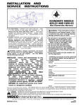
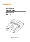
GIDM
INDUSTRIAL / COMMERCIAL
PACKAGED FURNACES
INSTALLATION, OPERATION AND MAINTENANCE MANUAL
(Suitable for Operation with up to 100% Fresh Air)
READ MANUAL CAREFULY BEFORE INSTALLING
OR OPERATING THE FURNACE
FOR YOUR SAFETY
If you smell gas follow these
instructions,
1) Open windows.
2) Do not touch electrical switches.
3) Extinguish any open flame.
4) Call the gas supplier immediately.
FOR YOUR SAFETY
The use and storage of gasoline or other
flammable vapors and liquids in open
containers in the vicinity of this appliance
is hazardous.
MODEL:
SERIAL NUMBER:
JOB:
DATE OF INSTALLATION:
WARNING
IMPROPER INSTALLATION, ADJUSTMENT, SERVICE OR MAINTENANCE CAN
CAUSE PROPERTY DAMAGE, INJURY OR DEATH. PLEASE READ THE
INSTALLATION, OPERATING AND MAINTENANCE INSTRUCTION
THOROUGHLY.
*THIS UNIT IS TO BE SERVICED BY QUALIFIED PERSONNEL*
**DO NOT TAMPER WITH THE UNIT OR CONTROLS**
INSTALLER’S RESPONSIBILITY
Installer please note: This equipment has been test fired and inspected. It has been shipped free from defects from
our factory. However, during shipment and installation, problems such as loose wires, leaks or loose fasteners may
occur. It is the installer’s responsibility to inspect and correct any problems that may be found.
INSTALLER/SERVICE CONTRACTOR
NAME:
ADDRESS:
TELEPHONE:
CONTACT:
RECEIVING AND WAREHOUSING
Inspect the unit upon arrival for any shipping damage. If any part is missing or damaged, notify the carrier at once.
If the unit cannot be installed immediately, store it and its accessories in a clean and dry place.
HANDLING AND SUSPENSION
Do not handle the unit by attaching hooks, jacks or chains to the unit casing or any other component. Spreader bars
are recommended when making single point lifts.
Horizontal indoor units may be handled and suspended using the lugs on the base frame.
Horizontal rooftop units are provided with base frame lugs.
Vertical upflow units (including AC model) and vertical down flow models are provided with eye bolts to ease
handling.
For all models, the heating and blower sections are shipped separately. (see Fig. 1 for exploded view). Assemble
the sections by aligning the pre-drilled flanges and securing the assembly with the fasteners provided. Use gasketing
material to prevent infiltration at the joints.
Optional sections such as mixing boxes are shipped separately. A list of these, along with any other unit components
that have been shipped separately from the unit, is included at the end of this manual.
GENERAL INSTALLATION NOTES:
This unit must be installed in accordance with the current standard CAN/CSA/1-B149.1 or CAN/CSA/1-B149.2.
Installation codes for gas burning appliances and equipment, and/or the applicable provincial regulations for the
class, which should be carefully followed in all cases. Authorities having jurisdiction should be consulted before
installations are made.
USA Units: Installation must be made in accordance with local codes, or in absence of local codes, with ANSI
Standard Z223.1-1992 (N.F.P.A. No 54) “National Fuel Gas Code”, or the latest edition of. All ANSI and NFPA
Standards referred to in these installation instructions are the ones that were applicable at the time the design of this
appliance was certified. The ANSI Standards are available from the American Gas Association, 1515 Wilson
Boulevard, Arlington, Virginia 22209. The NFPA Standards are available from the National Fire Protection
Association, Batterymarch Park, Quincy, Massachusetts 02269. The heaters are designed for use in airplane hangers
when installed in accordance with ANSI/NFPA No. 409 and in public garages when installed in accordance with the
NFPA No. 88A and NFPA No. 88B.
CLEARANCES
MODEL
C
D
R
M
AC
Notes:
CONFIGURATION
CLEARANCES TO COMBUSTIBLE
CONSTRUCTION ( in inches)
TOP FRONT FLUE BACK SIDES FLOOR
6
36
18
36
6
*
6
36
18
36
6
C
0
36
18
36
6
NC**
6
36
18
36
6
NC**
6
36
18
36
6
C
Horizontal Suspended
Vertical Upflow Floorset
Vertical Downflow Floorset
Horizontal Floorset
Vertical Upflow High Velocity Floorset
*Three inch bottom clearance.
** May be installed on combustible floor when mounted on 4-inch steel base channels. Floor clearance is
measured from bottom of unit casing.
1
For service, it is advisable to maintain a minimum 24-inch clearance on the side opposite the controls and 42-inch
clearance on the control side. If this unit is to be operated within a confined space or within a building of unusually
tight construction, air for combustion and ventilation must be obtained from outdoors or other spaces freely
communicating with the outdoors. At least one square inch of free area per 1000 Btuh of total input rating of all
appliances within the space provided up to 400,000 Btuh. Refer to CAN/CSA/1-B149.1 natural gas, or
CAN/CSA/1- B149.2 and B139, propane gas and B139 for air supply requirements of appliances heating input
exceeding 400,000 Btuh. For USA units refer to ASSI Z223.1 section 1.3.4.2 and 1.3.4.3 for combustion air
requirements.
Ducts connected to the furnace shall have removable access panels on both the upstream and downstream sides of
the furnace. These openings shall be accessible when the furnace is installed and shall be sized to allow the
observation of smoke or reflected light inside the casing to indicate the presence of leaks in the heat exchanger. The
covers for the openings shall be attached in such a manner as to prevent leaks.
The furnace must not be operated in the presence of chlorinated vapors. When such vapors mix with the products of
combustion, highly corrosive compounds result which will cause the premature failure of the heat exchanger and
other components, voiding the warranty.
CONNECTING THE FLUE
In making flue connections to the unit, observe the following general recommendations. In addition, these
connections must conform to the requirements of current CAN/CSA/B149.1 natural gas and CAN/CSA/ B149.2 and
be in accordance with provincial and local authorities who have jurisdiction. For USA units, all venting installations
shall be in accordance with the latest edition of Part 7, “Venting of Equipment”, of the National Fuel Gas Code,
ANSI Z223.1-1992 (or the latest edition), or applicable provisions of local building codes.
*See Fig. II and Fig. III for C vent system.
*Some jurisdiction may require a positive pressure vent system.
*The flue must be securely attached to the unit with tight joints.
*The pipe from the unit to the flue should rise at least ¼ inch per foot.
*The flue must not be sized to have a cross-sectional area less than that of the flue collar at the
unit. See Fig. II and Fig. III.
*Other appliances must not be connected so as to vent through the flue of this unit.
*Do not use 90-degree tees or elbows greater than 45 degrees.
*Do not support the weight of the stack on the flue connection of the heating section.
*Minimize connecting pipe length and the number of bends by locating the unit as close to the flue pipe as
possible.
*Maintain clearances between the flue pipe and combustible materials that are acceptable to the federal,
provincial and local authorities having jurisdiction.
*Unit must be connected to a flue having sufficient draft to ensure proper operation of the unit.
2
1) FOR POWER VENTED UNITS: The flue draft should be adjusted at the damper of the induced
draft fan when the unit is operating on high fire. The overfire draft measured with a manometer at the
test port in the relief door should be minus 0.01 to minus 0.50 in W.C. as specified on the rating plate
of the unit.
2) FOR GRAVITY VENTED UNITS: The flue draft should be adjusted at the damper of the burner fan
when the unit is operating at high fire. The overfire draft measured with a manometer at the test port in
the relief door should be positive 0.01 to positive 1.0 in W.C. as specified on the rating plate.
ELECTRICAL CONNECTIONS
NOTE: This unit has been examined and tested for compliance with CSA C22.2 No. 0 and CSA C22.2 No. 3.
All electrical work must conform to the requirements of the current CSA standard C22.1 Canadian Electric Code
Part 1 and local ordinances.
Control voltage is as indicated on the rating plate.
Follow the wiring diagram supplied with the unit. This type of unit is available with a variety of fuel control
schemes. Please ensure that you are using the correct wiring diagram for installation or trouble shooting.
If a space thermostat is used with the furnace, locate the thermostat so that cold drafts and hot discharge air streams
do not affect its performance. Do not mount the thermostat on the casing on the unit, as it will be affected by
radiated and conducted heat. Refer to the instructions furnished with the thermostat for further details.
If any of the original wire as supplied with the unit must be replaced, it must be replaced with type TEW 105 degrees
or its equivalent except where noted.
Temperature controllers, limit controllers, remote selector switches, door switches or any other auxiliary electrical
items must be connected to the terminals provided and shown on the wiring diagram.
For units shipped in two sections, electrical connections between sections are to be made by installer in the field.
Field wiring to be done by the installer is denoted by dotted lines on the wiring diagram. Solid lines on the wiring
diagram indicate factory wiring by the manufacturer.
NOTE: Because bolts and set screws may become loose during unit shipment, such fasteners should be tightened
upon installation.
WARNING: Fire or explosion hazard can cause property damage, severe injury, or death. Check for gas
leaks with rich soap and water solution any time work is done on a gas line. Never use an open
flame to detect gas leaks.
GAS PIPING
All gas piping should be in accordance with CAN/CSA/1-B149 and the regulations of local authorities having
jurisdiction. Emergency manual shut down valve should be provided upstream of piping to unit and should be
labeled for quick identification. Color coding of gas piping is also recommended.
Carefully check the unit rating plate for fuel type and supply pressure.
*Locate the high pressure regulator, if required, at least five feet from the unit.
*Gas lines must not be located in such a way as to hinder access to the unit
3
*A tee shall be installed in the supply line at the same elevation as the gas inlet connection. The tee must be
equipped with a nipple and pipe cap to serve as a condensate collector.
*Test for tightness of gas connections after installation.
GAS VENT
High gas pressure regulator (if required), low pressure regulator, pilot pressure regulator, gas pressure switch (if
supplied), and normally open vent valve (if supplied) must be vented outside of building for an indoor unit. (Check
with authorities having jurisdiction).
GENERAL OPERATING INSTRUCTIONS
WARNING: Fire or explosion hazard can cause property damage, severe injury, or death. Check for gas
leaks with rich soap and water solution any time work is done on a gas line. Never use an open
flame to detect gas leaks.
GAS-FIRED UNITS
Refer to the rating plate for fuel input and supply pressures.
DO NOT ATTEMPT TO START THE BURNER IF THE UNIT IS FULL OF VAPOR OR GAS, OR IF THE
COMBUSTION IS VERY HOT.
DO NOT USE THIS UNIT TO BURN GARBAGE OR PAPER.
DO NOT LEAVE COMBUSTIBLE MATERIALS NEAR THE UNIT.
SHUT OFF THE MANUAL FUEL SUPPLY VALVE IF THE BURNER IS SHUT DOWN FOR AN EXTENDED
PERIOD OF TIME.
ENSURE CLEAN-OUT DOORS ARE IN PLACE BEFORE STARTING THE BURNER.
DO NOT START THE BURNER UNLESS THE BLOWER ACCESS DOORS ARE SECURELY IN PLACE.
START-UP PROCEDURES
WARNING: Fire or explosion hazard can cause property damage, severe injury, or death. Check for gas
leaks with rich soap and water solution any time work is done on a gas line. Never use an open
flame to detect gas leaks.
PRECAUTIONS
1.
Ensure the main disconnect switch is in the “off” position.
2.
Ensure the burner on-off switch is in the “off” position.
3.
Check all electrical connections and tighten if necessary.
4.
Check main fans (by rotating fan shaft by hand), bearing set screws, exhauster wheel, and pulley set screws.
4
5.
Lubricate (if necessary) the burner, induced draft fan and main fan motors. The specifications on
the motors for grease and oil shall be adhered to.
6.
Check heater outlets and exhauster, or induced draft discharge for obstructions.
7.
Check fan-limit control. Setting should be as follows:
MODEL
CONFIGURATION
MAIN
AUXILIARY
LIMIT
FAN*
LIMIT
FAN*
C
Horizontal Suspended
240
120
NA
NA
D
Vertical Upflow Floorset
180
80
NA
NA
R
Vertical Downflow Floorset
180
80
165
100
M
Horizontal Floorset
240
120
NA
NA
AC
Vertical Upflow Floorset
180
80
NA
NA
*Fan “ON” settings, set differential for Fan “OFF” 15-20 degrees below fan setting.
8.
Ensure that the flue is in place and providing proper overfire draft as noted in previous section on
“Connecting the Flue”.
9.
The induced draft proving switch (power vented units only) is factory set and must not be tampered with. This
switch will not allow unit operation if overfire draft is outside of the acceptable operating range.
10. Check all fuse blocks to determine that all fusing is installed.
11. Set the operating controls (eg. thermostat, remote panel switches) so as to allow heating
operation of the unit.
12. Reset the primary flame safeguard by pushing the reset button or lever.
13. Reset motor starter by pushing the reset button, if so equipped.
14. Check building system gas supply and be sure all lines are purged of air.
15. Check building system gas supply pressure.
CAUTION - GAS UNITS
At maximum input the gas pressure must fall within the range specified on the unit rating plate.
Optional high and low gas pressure switches (if supplied) must be reset.
16. Check all piping for tightness and correct any signs of leaks.
WARNING: Fire or explosion hazard can cause property damage, severe injury, or death. Check for gas
leaks with rich soap and water solution any time work is done on a gas line. Never use an open
flame to detect gas leaks.
START-UP
1.
Refer to factory test report for correct settings that are to be checked on the unit.
2.
Check the supply fan motor thermal overload setting against the rating plate figure.
3.
Ensure burner on-off switch is “off”. (On heating units using a fan plenum switch, jumper the fan switch).
4.
Put the main disconnect switch in the “on” position, thus activating the supply fan. Check for correct direction
of rotation.
5
5.
Check supply fan motor load against rating plate figure. If actual figure is significantly different than the rating
plate value, take corrective actions with respect to duct work and accessories external to the unit
6.
The thermal overloads must be left set appropriate to the motor performance after all adjustments have been
made.
7.
Repeat steps 2 through 6 for the induced draft fan motor (power vented units only).
8.
Remove jumper from fan switch if installed in step 4 above.
9.
Ensure all manual fuel valves are open.
10. Turn on-off switch on burner to “on” position.
11. Check direction of rotation of burner fan.
12. Set thermostat to temperature desired.
13. After a prepurge period the pilot will light and main burner will energize. Check for good clean flame and
smooth light-off conditions.
14. Check unit performance as described on the factory test report. (Include items such as stack temperature, CO-2
level, flame signals, etc.). Readings obtained in the field should not deviate significantly from those obtained at
the factory.
SHUT DOWN
EMERGENCY SHUT DOWN
1.
Set disconnect switch to “off” position.
2.
Close the manual main fuel valve.
3.
Set the burner on-off switch to “off” position.
SERVICE SHUT DOWN
1.
Set the burner toggle switch to “off” position.
2.
Close the manual main fuel valve.
3.
Set the operating controls (eg. thermostat, remote panel switches) so as to prevent heating operation.
TROUBLE SHOOTING GUIDE
WARNING: Fire or explosion hazard can cause property damage, severe injury, or death. Check for gas
leaks with rich soap and water solution any time work is done on a gas line. Never use an open
flame to detect gas leaks.
6
The equipment has been electrically and fire tested prior to shipment. However, during transit, misadjustment of
controls and loose wires could develop. Do not assume a control is defective until it and its associated wiring is
checked.
This equipment has may items supplied to us by outside vendors. This manual is accompanied by information sheets
on most of these items which should be referred to for detailed service information.
The following is an obvious list of items that could cause field problems; however, it does not cover all problems
encountered and is meant to be used as a guide only.
1.
EXHAUSTER* AND/OR BURNER MOTORS FAIL TO RUN. CONTROL RELAY DOES NOT
FUNCTION.
A)
B)
C)
D)
E)
F)
G)
2.
Blown fuses. Main disconnect open.
Control relay off on flame failure. Push reset button on control.
Thermostat or duct stat not calling for start-up. Defective control.
Loose wire or low voltage.
Motor overcurrent protector tripped in open position or defective.
Controls in limit circuit defective or tripped in open position.
Control transformer defective.
EXHAUSTER* AND/OR BURNER MOTORS RUN, NO IGNITION OR MAIN FLAME. PRIMARY RELAY
WILL NOT INDICATE FLAME FAILURE.
A)
B)
C)
D)
Exhauster* and/or burner motors running backwards.
Misadjusted draft.
Misadjusted or defective exhauster draft switch*.
Main safety gas valve proof of closure switch and/or low fire proving switch (on modulating burners only)
not made.
E) High or low gas pressure switch tripped.
3.
EXHAUSTER* AND/OR BURNER MOTORS RUN, NO IGNITION OR MAIN FLAME. PRIMARY
RELAY LOCKS OUT ON FLAME FAILURE.
A) Fuel valve manually closed.
B) Ignition transformer or pilot defective. Defective or improperly gapped ignition electrodes. Cracked
porcelain.
C) Broken or loose wire in fuel circuit.
D) Gas nozzles obstructed or plugged.
E) Gas pilot valve defective. Main fuel valve defective.
F) Insufficient fuel at supply. Air in system.
4.
BURNER SHORT CYCLES.
A) High limit switch misadjusted or defective.
B) Draft switch* misadjusted or defective.
C) Various ductstats defective or settings improper.
5.
EXHAUSTER* AND/OR BURNER MOTORS RUN, IGNITION AND MAIN FLAME. MAIN FAN MOTOR
FAILS TO OPERATE.
A) Automatic fan switch not set properly or defective.
B) Blown fan fuses.
C) Motor overcurrent protector tripped open or defective.
7
6.
UNABLE TO ADJUST FIRE TO BURN CLEANLY.
A)
B)
C)
D)
E)
7.
Insufficient exhauster* draft.
Insufficient or too much fuel at supply.
Incorrect adjustment of air shutters at burner.
Insufficient combustion air available.
Burner blower wheel running backwards.
INSUFFICIENT HEAT BEING DISCHARGED INTO AREA.
A)
B)
C)
D)
E)
Main fan blowers running backwards.
High limit switch setting too low or defective.
Burner locked in low fire position.
Ductstat setting improper or defective.
Field mounted thermostat and/or ductstats improperly wired.
*APPLIES TO POWER VENTED UNIT ONLY.
MAINTENANCE
Regular maintenance is necessary to ensure the efficient operation and long life of this unit. This maintenance should be
performed by, or supervised by, qualified service personnel. A maintenance schedule should be prepared for the unit
based on its application and location.
RECOMMENDED MONTHLY MAINTENANCE
1.
2.
3.
4.
5.
6.
7.
8.
9.
10.
Check for loose connections in the wiring.
Check the voltage at the unit while it is in operation.
Check motor amperage draws against rating plate values.
Inspect all contactors to ensure that they are clean and making good contact.
Check all fittings, valves and lines for leaks.
Check the burner; clean and adjust if necessary.
Check the flame sensor; clean if necessary.
Check the fuel supply pressure to the unit.
On gas fired units, check the manifold pressure.
Clean or replace air filters if necessary. Replace filters only with type equivalent to those supplied with the unit
by the factory.
11. Check all damper, linkages and damper actuators; adjust and tighten as required.
12. Check all belts; adjust or replace as necessary.
13. Check operation of all safety controls.
RECOMMENDED YEARLY MAINTENANCE
1.
2.
3.
4.
5.
6.
7.
8.
Perform the monthly maintenance recommended.
Inspect blower wheels and housing; clean if necessary.
Inspect all set screws on blower wheels and pulleys to ensure that they are secured to their respective shafts.
Check ignition spark and adjust gap if necessary.
Inspect and clean ignition electrodes.
Check flame supervisor relay.
Inspect all operating and safety controls; clean and replace if necessary.
Inspect the header box and secondary tubes through the access panels provided. Check for carbon deposits,
soot, scale, or rust; clean as required. Check condition of flue pipe.
9. Clean the primary combustion chamber.
10. Clean the burner.
8
NOTE: Refer to manufacturer literature provided for maintenance requirements of optional equipment.
BEARING INSTALLATION AND MAINTENANCE
NOTE: To prevent premature failure – please ensure greasing instructions below are applied. As well,
tighten bearing set screws, collars, and wheel lugs every four to six months.
ENGINEERING – BALL & ROLLER BEARINGS LUBRICATION
For bearings that are equipped with a hydraulic grease fitting threaded into the housing for ease of lubrication, the
proper amount of lubricant in the bearing is important. Both excessive and inadequate lubrication may cause failure.
The bearings should be re-lubricated while they are rotating (if it is safe to do so); the grease should be pumped in
slowly until a slight bead forms around the seals. The bead in addition to acting as an indicator of adequate relubrication provides additional protection against the entry of foreign matter and helps flush out contaminates in the
bearing.
By the time the slight bead is formed, it will be noticed that the bearing temperature will rise. It is not uncommon for
the temperature to rise as much as 30 degrees Fahrenheit after re-lubrication. If necessary to re-lubricate while the
bearing is idle, refer to the recommended re-lubrication grease chart tables on the following page for various sizes of
the bearings.
Lubricant-Standard Bearings:
All bearing units are pre-lubricated at the factory with a lithium soap grease which is compatible with multi-purpose
grease readily available from local suppliers. The lubricant selected for factory lubrication uses a highly refined
mineral oil with a high viscosity index, thickened with lithium soap to conform to NLGI grade 2 consistency. A
suitable additive package is added to protect the highly polished rolling contact surfaces from corrosion and
oxidation of the lubricant. The lubricant is satisfactory for an operating temperature range of –30 F to +250 F.
Select standard industrial grade greases that conform to the following specification for optimum bearing
performance:
General Duty Ball & Roller;
58-75 SUS @ 210 F
450-750 SUS @ 100 F
Premium Duty Ball & Roller;
68-75 SUS @ 210 F
600-750 SUS @ 100 F
Heavy Duty Roller Bearing;
82 SUS @ 210 F
886 SUS @ 100 F
NOTE: For heavy loaded roller bearing applications, grease with EP additives are often recommended for optimum
performance.
9
Table 1.
Recommended Lubrication
Ball Bearings
Shaft Size
(inches)
1/4 to 3/16
1/2 to 3/4
1-1/4 to 1-1/2
1-11/16 to 1-15/16
2 to 2-7/16
2-1/2 to 2-15/16
3 to 3-7/16
3-1/2 to 4
-
Roller Bearings
Grease Charge
(ounces)
0.03
0.1
0.15
0.2
0.3
0.5
0.85
1.5
-
Shaft Size
(inches)
1-3/16 to 1-1/4
1-3/8 to 1-7/16
1-1/2 to 1-11/16
1-3/4 to 2
2 to 2-3/16
2-1/4 to 2-1/2
2-11/16 to 3
3-3/16 to 3-1/2
3-15/16 to 4
4-7/16 to 4-1/2
Grease Charge
(ounces)
0.1
0.22
0.32
0.5
0.55
0.65
0.85
1.25
2.5
3.1
Frequency of re-lubrication depends upon operating conditions. The bearing operating temperature is the best index
for determining a re-lubrication schedule. The following chart gives the frequency of re-lubrication based upon
continuous operation for various operating temperatures and can be used as a satisfactory guide for determining
when bearings should be re-lubricated.
Table 2.
Lubrication Frequency
Speed
Temperature
Cleanliness
Greasing Interval
100 RPM
500 RPM
1000 RPM
1500 RPM
Any speed
Any speed
Any speed
Any speed
Up to 120 F
Up to 130 F
Up to 210 F
Over 150 F
Up to 150 F
Over 150 F
Any temperature
Any temperature
Clean
Clean
Clean
Clean
Dirty
Dirty
Very dirty
Extreme conditions
5 months
2 months
2 weeks
Weekly
1 week to 1 month
Daily to 1 week
Daily to 1 week
Daily to 1 week
10
TENSIONING V-BELT DRIVES
1.
2.
3.
4.
5.
Ideal tension is the lowest tension at which the belt will not slip under peak load conditions.
Check tension frequently during the first 24-48 hours of operation.
Over-tensioning shortens the belt and bearing life.
Keep belts free from foreign material that may cause slip.
Make V-drive inspection on a periodic basis. Tension when slipping. Never apply belt dressing as this will
damage the belt and cause early failure.
Check and tighten belt tension. The following procedure is recommended for tightening belts:
a) Measure span “X” shown in Figure A.
b) At the center of span length “X”, apply a force perpendicular to the span and large enough to deflect belt
1/64” for each inch of span length. Example- the required deflection for a 40” span would be 40/64” or
5/8”.
c) Compare the force applied with the values given in Table III. If force is between the minimum and
maximum range shown, the drive tension should be satisfactory. A force below the minimum value
indicates an under tightened belt and force that exceeds the maximum value indicates an over tightened belt.
FIGURE A
SPAN LEN
GT
HX
FORCE
DEFLECTION 1/64”
PER INCH OF SPAN
TABLE III
BELT CROSS MOTOR PULLEY
SECTION
PITCH DIAMETER
(Marked on Belt)
3.0” - 3.6”
A
3.8” - 4.8”
5.0” - 7.0’
3.4” - 4.2”
B
4.4” - 5.6’
5.8” - 8.6”
11
DEFLECTION FORCE
MINIMUM
MAXIMUM
2.62lbs.
3.0lbs.
3.25lbs.
3.0lbs.
4.0lbs.
5.25lbs.
3.25lbs.
4.0lbs.
5.0lbs.
5.0lbs.
5.87lbs.
7.87lbs.
GIDM INDUSTRIAL HEATER - WARRANTY
I.C.E. MFG. LTD. WARRANTS THAT IT WILL SUPPLY TO OR REPAIR FOR THE PURCHASER OF THIS
PACKAGE UNIT HEATER THE HEAT EXCHANGER FREE OF CHARGE F.O.B. FACTORY IF SAID HEAT
EXCHANGER WEARS OUT OR FAILS UNDER NORMAL USE AND SERVICE DUE TO A DEFECT IN
MATERIAL AND/OR WORKMANSHIP DURING FIVE (5) YEARS FROM DATE OF SHIPMENT FROM THE
FACTORY PROVIDED AN ALL STAINLESS HEAT EXCHANGER IS PROVIDED. COMBINATION
STAINLESS STEEL WITH MILD STEEL SECONDARY HEAT EXCHANGERS ARE WARRANTED FOR
ONE (1) YEAR.
ALL MECHANICAL COMPONENTS, MOTORS, BLOWERS, VALVES, AND CONTROLS ARE COVERED
BY A ONE (1)YEAR LIMITED WARRANTY.
THIS WARRANTY DOES NOT INCLUDE ANY FREIGHT, LABOUR, OR SALES TAXES THAT MAY BE
INCURRED BY THE PURCHASERS AND IS SUBJECT TO THE FOLLOWING CONDITIONS.
1) THE UNIT SHALL BE INSTALLED BY A QUALIFIED HEATING CONTRACTOR IN ACCORDANCE
WITH PROVISIONS OF THE SERVICE MANUAL.
2) THE UNIT SHALL HAVE BEEN INSTALLED IN ACCORDANCE WITH ALL PROVINCIAL AND
LOCAL CODES.
3) THE UNIT SHALL HAVE BEEN SUBJECT TO ONLY NORMAL USE IN SERVICE AND SHALL NOT
HAVE BEEN MISUSED, NEGLECTED, ALTERED OR OTHERWISE DAMAGED.
4) THE UNIT SHALL HAVE BEEN OPERATED WITHIN ITS PUBLISHED CAPACITY AND WITH THE
PRESCRIBED FUEL.
5) ALL AUTOMATIC CONTROLS SHALL HAVE BEEN OPERATIVE AT ALL TIMES.
6) THE UNIT HAS NOT BEEN ALLOWED TO EXCEED IT’S PROPER TEMPERATURE LIMITS DUE TO
CONTROL MALFUNCTION OR INADEQUATE AIR CIRCULATION.
7) THERE IS NO EVIDENCE OF TAMPERING OR DELIBERATE DESTRUCTION.
8) THE UNIT HEATER HAS NOT BEEN SUBJECT TO AIR FOR COMBUSTION CONTAMINATED WITH
FLUORIDES, DRY CLEANING FLUID VAPORS HAIRDRESSING FLUID VAPORS, (OR ANY VAPORS
FOUND TO HAVE ADVERSE EFFECT ON METALS).
NO REPRESENTATIVE OF ICE MFG. LTD., NOR ANY OF ITS DISTRIBUTORS OR DEALERS, IS
AUTHORIZED TO ASSUME FOR ICE MFG. LTD. ANY OTHER OBLIGATIONS OR LIABILTY IN
CONNECTION WITH THIS PRODUCT, NOR ALTER THE TERMS OF THIS WARRANTY IN ANY WAY.
THIS WARRANTY IS LIMITED TO THE EXPRESS PROVISIONS CONTAINED HEREIN AND DOES NOT
EXTEND TO LIABILITY FOR LABOUR COSTS INCURRED IN REPLACING DEFECTIVE PARTS.
AUTHORIZATION TO RETURN ANY ALLEGED DEFECTIVE PARTS MUST BE OBTAINED FROM THE
FACTORY BEFORE THE PART IS TRANSPORTED AND THE TRANSPORTATION CHARGES FOR ANY
ALLEGED DEFECTIVE PARTS SHALL BE PREPAID BY THE OWNER. ICE MFG. LTD. WILL NOT
ACCEPT CHARGES FOR PARTS PURCHASED UNLESS THE CONDITIONS OF THIS WARRANTY HAVE
BEEN SATISFIED.
THE EXPRESS WARRANTIES HEREIN CONTAINED ARE IN LIEU OF ANY OTHER WARRANTIES,
EXPRESSED OR IMPLIED, INCLUDING THE WARRANTY OF MERCHANTABILITY AND OF FITNESS
FOR ANY PARTICULAR PURPOSE. ICE MFG. LTD. SHALL NOT BE LIABLE FOR DAMAGES,
INCLUDING SPECIAL, INCIDENTAL, OR CONSEQUENTIAL DAMAGES ARISING OUT OF,OR IN
CONNECTION WITH THE PERFORMANCE OF THE GIDM SERIES UNIT HEATER OR IT’S USE BY THE
OWNER. ICE MFG. LTD. LIABILITY IS LIMITED EXCLUSIVELY TO REPAIR AND OR REPLACEMENT
OF THE DEFECTIVE PART. PARTS CAN BE OBTAINED FROM ICE MFG. LTD. WINNIPEG, MANITOBA
ON THE BASIS THAT CREDIT WILL BE ISSUED IF DEFECTIVE PARTS RETURNED QUALIFY FOR
REPLACEMENT PURSUANT TO THE TERMS AND CONDITIONS OF THIS WARRANTY.
12
ECONOMITE 400-33 & F400-33 GAS BURNERS
INITIAL START UP AND ADJUSTMENT
CAUTION: Only qualified service personnel should attempt initial start-up.
1. Study these instructions, the wiring diagrams and flame safeguard instructions. Locate and identify all of the
burner components.
2. Have on hand: CO and CO2 tester, stack thermometer, 0” to 30” W.C. gas pressure gauge, U-Tube manometer
and DC volt meter.
3. Make the proper setting on all limit controls and set the operating control to call for heat.
4. Check the piping for leaks. A quick way to do this is to turn off main shut-off valve “A” and pilot valve “B”,
then turn on the gas pressure to the gas supply line and observe the meter test dial. There should be no
movement of the dial hand for at least five minutes on a half foot dial (proportionally longer on larger dials).
All other gas appliances must, of course, be completely shut off during this test. If a leak is detected it should be
located with a soap suds test and corrected. If air or inert gas (do not use oxygen) under pressure is used for
leak detection, do not subject the main and pilot valves or regulators to pressure readings exceeding ½ PSI
(disconnect piping to prevent damage during high pressure leak testing).
5. Purge the gas supply line up to the main and pilot manual valves. Do not purge into the combustion chamber.
6. Make sure that the main and pilot manual gas valves are closed and that the burner line switch is off.
7. The pilot gas pressure regulator is set for 3 ½ ” W.C. outlet pressure which is suitable for natural gas and
average draft conditions. If propane gas is to be used, adjust the regulator to its minimum outlet pressure
setting.
8. Firmly push in the flame safeguard manual reset button “C” and the Model F400 motor manual overload reset.
9. Check that the blower motor rotates freely.
10. Turn line switch on momentarily and check for proper blower wheel rotation.
11. Open pilot manual valve “B”.
12. Trial for pilot ignition. Turn switch to winter operation. If power vented, burner will be powered when air
switch contacts close. Flame safeguard is powered, motor relay 3K pulls in. As motor reaches operating speed,
the blower interlock switch “makes” to initiate a 30 second prepurge period. After prepurge, the load relay 1K
pulls in to energize the pilot solenoid and ignition transformer and the pilot should light.
13. If the pilot fails to light during the 15 second trial, it is probably due to air in the pilot line. Wait one minute and
push flame safeguard reset button to restart, (400 motor will continue to run during the safety lockout. F400
motor will stop approximately 15 seconds after solenoid valve closes).
14. Observe the pilot flame. If it is weak, screw in the pilot regulator adjustment. If it is excessively rich and large
or floating from the pilot tip, back off the regulator adjustment. Set the pilot to a stable blue flame which burns
firmly within the pilot tip. Check flame current with a DC volt meter. It should show a steady 15-17 volts
(Fireye) or 3-5 VDC (Honeywell). Operate air shutter throughout range to check pilot stability. Adjust pilot
regulator slowly to obtain highest reading possible, try several relights.
15. Set the shutter to match the intended input, i.e. full open for maximum, closed for minimum or partially open
for mid-range.
16. Slowly open main manual valve until the main flame ignites. Continue to open valve, adjusting air shutter if
necessary, if the manual valve is fully opened before input is reached, screw in regulator adjustment. Set
regulator to desired manifold pressure, marked on the rating plate.
NOTE: Do not screw the adjusting nut in past the point where no further increase in manifold pressure is noted.
If the specified pressure cannot be reached, check for proper inlet pressure at the inlet of the main manual valve
with the burner running.
17. Readjust the main air shutter to provide a quiet soft flame-blue at the burner nozzle with well defined orange tips
for natural gas or with well defined yellow tips for propane.
18. The primary air adjustment which affects the flame length, has been set wide open for average conditions.
Decrease the primary air if a longer, softer flame is desired.
19. Cycle the burner on and off several times to check its operation.
20. Check the operation of the limit and operating controls.
21. Check the flue gas temperature ahead of the diverter. It should be above 300°F . Excessive flue temperatures
will result in low efficiencies. Low flue temperatures may cause excessive condensation. Reset gas input if
necessary to adjust stack temperature, (on/off operation only).
13
22. Make the final setting of the air shutter by checking the flue gases with an “Orsat” or other similar combustion
testing instrument. There should be no carbon monoxide and the carbon dioxide content should be within limits
prescribed by the local gas company. Make sure that the main air shutter is locked securely in place.
23. Recheck pilot to make sure that its operation has not deteriorated because of main shutter adjustment. If
necessary, readjust pressure regulator.
24. Modulation operation: see wiring diagram and modulating instruction sheets supplied with this unit for correct
set up.
25. If linkage between Butterfly valve and Burner (gravity unit only) and venter fan if power vented needs to be
adjusted from factory setting, (see below).
GIDM LINKAGE SET-UP WITH POWER VENTS
1. Install a manometer on suction at test port in pop-up door.
a) Ensure there is a negative pressure at that point on low fire through to high fire.
- .50 to - 75” W.C. low fire and -.01 to -.10 on high fire.
2. To increase exhaust move drive rod toward damper pin (decrease the distance between drive rod and center pin).
3. To increase combustion air move drive rod towards center pin (decrease the distance between drive rod and
center pin).
4. To ensure a negative pressure throughout full modulation range, you may have to speed up exhaust and or burner
damper to match gas flow to the burner.
Move drive rod closer to the drive pin on the butterfly valve, (this will reduce the movement of the burner
damper).
5. Adjust low and high fire on the stop screws on the butterfly valve.
NOTE: The motor is allowed to over run with the spring linkage set the travel on the Penn Johnson motor to ensure
it does not go to far or damage to the motor could occur.
MINIMUM EQUIPMENT TO START-UP AND SET-UP GIDM GAS BURNER
1.
2.
3.
4.
5.
CO and CO2 tester.
Stack thermometer.
0” to 10” W.C. gas pressure gauge or magnehelic 0” to 10” W.C.
U-tube manometer or -5” to +5” magnehelic gauge.
DC volt meter.
14
ECONOMITE 400-33 & F400-33 GAS BURNERS
PART #
DESCRPTION
3981-001 4” Diameter Stainless Sleeve
PART #
5253-01
4904-45
Quadrant-Air Shutter Adjustment
5253-10
DESCRIPTION
Pilot assembly with insulators, rods, temflex and
baffle.
PVC tubing—7/16”I.D. x 2” long
4905-15
Air shutter-Internal
5234-40
Flame rod Gland Nut
4917-00
Main Orifice Holder
5234-50
Flame rod assembly.
4918-11
Orifice Elbow (1” NPT)
5249-01
Pilot air baffle.
4919-60
Blower Wheel with centrifugal actuator and Disc
5249-32
Spark rod assembly.
4919-90
Centrifugal Actuator Disc
5250-00
5272-00
Pilot tip with cone less insulators, rods, temflex
and baffle.
Blower inlet grille.
5939-01
Flame rod wire--5” through 9” burner tube.
8433-06
Pilot spud (.021)—PROPANE (3N4-021,
Y90AA-5232).
8433-10
Pilot spud (.032)—NATURAL (2-15M1-032,
Y90AA-5232).
4927-509 1/6 HP motor 120/1/60 [G.E. 5KH35FN123X
(note 1/3 HP substitute), 5KH33DG655Y,
5KH33DN171Y; Dayton 6K149; Marathon
48S34D191A, 48S34D203; Universal Electric
HH1E001N; Century X-173668-XX]
4922-90
Primary Air Shutter Kit
4924-10
Inlet Side Plate
4944-02
Main Spud 25/64” (.390) minimum capacity-NATURAL—drill 7/16” (.437) for 400/540 MBH
range and omit for 540/700 range
4944-03
Main Spud #21 Drill(.390) minimum capacity-PROPANE—drill for desired capacity per manual
8437-419 1/6HP totally enclosed motor 115/1/60 (Century
X-176797-XX) special and Canadian burners
only. Not interchangeable with drip proof motor
4921-50.
8447-11
Ignition transformer 120/1/60 primary, 6000 volts
secondary (Webster 612-6A020, 612-6A044;
France 3RABVR-19; Jefferson #638-181).
4944-10
Main Spud Extension
4946-00
Motor Spacer (4 required)
8450-21
Orifice holder sealing gasket.
4959-05
External Pilot Air Tube Kit
8451-06
Spark rod insulator sleeve.
5201-00
½” sq. pass thru for 1/4” tube fitting (gas line)
8484-72
Heyco strain relief (SR-4K-1)--Flame rod wire.
5201-10
½” sq. pass thru for 5/16” tube fitting (air line)
8484-75
Heyco strain relief (SR-11-2)--Spark rod wire.
5202-08
Pilot Spud #55 (.052) drill [was #54(.055)]-NATURAL AND PROPANE
8484-78
Heyco snap bushing (B-8875-750).
8502-05
Spark cable--15” burner tube.
5211-51
Motor, wheel and side plate assembly 120/1/60
8502-06
Spark cable--5” through 9” burner tube.
8423-16
Blower interlock switch (MICRO BZ-2RQ174-A2).
5225-263 Blower housing and burner tube assembly--9”
WARNING: Explosion hazard. Can cause serious injury or death. This device can malfunction if it gets wet. Never try to use a device
that has been wet - replace it.
DECODING CENTURY MOTOR NUMBERS. Single digit prefix denotes manufacturer’s location. Double digit suffix denotes
manufacturer’s mechanical code.
15
GP TYPE C FORCED DRAFT BURNER C-6.2 TO C-12.9
INITIAL START UP
1. Make sure burner power switch is off and manual main and pilot valves are closed.
2. Make proper settings on limit controls.
3. Have on hand CO and CO2 tester, stock thermometer, 0” to 30”W.C. gas pressure gauge, u- tube manometer and
D.C. volt meter.
4. Turn on burner power switch momentarily to check blower rotation.
5. Check gas tightness of main and pilot safety shut off valves (if used) by connecting a pressure gauge to the
pressure tap located between the safety shut-off valve and the test firing valve. When the test firing valves are
closed and the manual shut-off valves are opened, no pressure rise should show on the pressure gauge.
6. The air damper has been factory set approximately during test firing if need to adjust see linkage set up sheet
provided with unit. Turn on the burner switch, while the main and pilot gas firing valves are closed. After the
prepurge the ignition transformer and solenoid valves will be energized. Observe the ignition spark for proper
location and firmness. After the trial for ignition time, the ignition transformer and solenoid valve are
deenergized and the burner will lock out.
7. Open the pilot test firing valve and turn on the burner switch, while the manual main shut-off valve stays closed.
After the prepurge, the ignition transformer and the pilot solenoid valve are energized. Observe the pilot flame
and if necessary, adjust the pilot pressure regulator to obtain a stable flame with the highest steady flame signal.
For flame signal readings, see attached flame safeguard manual. With the main manual shut-off valve still closed,
the flame safeguard will lock out after approximately 10 seconds, only with high/low and modulating burners
which use an interrupted pilot. Repeat the ignition cycle a few times to ensure a fast ignition and stable pilot
flame.
8. Open the main manual shut-off valve and set the high/low limit switch and the modulating controller so that after
establishing a main flame, the burner will travel to high fire. Start the burner. In high fire, check the manifold
pressure with the required pressure for the firing rate, (see suggested inspection list) and if necessary, adjust
pressure regulator. Readjust the air damper if fire looks to lean or too rich.
9. Take a gas meter reading and readjust manifold gas pressure if necessary. Take a CO2 or O2 and a CO reading.
CO2 should be between 8-1/2 and 9-1/2 % and O2 should not be more than 5%, both with a maximum CO reading
of .04%. Readjust air damper accordingly.
10. With high/low and modulating burners, mark the high air damper position and set the high/low limit control or
modulating control so that the burner travels to low position. Visually adjust the input adjuster on the main gas
shut-off valve actuator if low fire is too rich or too lean. Take gas meter reading and readjust the input adjuster
according to the required low fire input, but not less than indicated in the specifications table. In order to keep
the high fire setting unchanged when adjusting the low fire air damper position, drive the burner to high fire,
change the positioning of the linkage as indicated in “Low Fire Adjustment”, drive the burner back to low fire
and check the CO2 or O2 readings. Repeat this procedure until a satisfactory setting is obtained.
11. Make sure all linkage connections are tight and check the readings in high and low fire again.
11a. The motor is allowed to over run with the spring linkage. Set the travel on the Johnson motor to ensure it does
not go too far, or damage to the motor could occur.
12. Reset controller and limits to their desired settings.
WARNING
DO NOT ADJUST FLAME VISIBLY. INSTRUMENTS ARE THE ONLY SAFE AND
RELIABLE MEANS TO DETERMINE THE PROPER ADJUSTMENTS.
16
BURNER SAFETY CHECK
1. Start and stop burner several times to ensure proper operation.
2. Check operation of combustion safeguard control by simulating a flame failure, making certain the burner locks
out on safety within the proper time.
3. Check operation of the air flow switch, making certain fuel valve closes when the air flow diaphragm switch
opens.
4. Bypass discharge controller and check to ensure high limit will shut down burner on temperature increase. If
changed reset as per factory setting.
5. Reset operating control to desired temperature. Permit burner to run until it is shut off by the operating control.
Adjust operating control, if necessary, until it causes burner to stop and start within desired range.
6. With the burner running, check hi and low gas pressure switch if on manifold. The burner should shut off
immediately.
7. Conduct minimum, pilot turn down test, reduce gas pressure to pilot with manual shut off cock to the point pilot
flame is extinguished or fails to prove. Increase gas flow slightly. Main flame must be ignited with this pilot
flame.
8. The following readings should be taken and record after final adjustments have been made.
a) Burner input (CFH gas).
b) Percent CO2 or O2.
c) CO indication.
d) Stack temperature.
e) Firebox pressure.
f) Fuel pressure (in W.C.-gas) (main and pilot).
g) Voltage to burner.
9. Give instruction to owner (operator).
WARNING: SHOULD OVERHEATING OCCUR
1. Shut off the manual gas control (s) to the burner.
2. Do not shut off the control switch to the pump or blower.
17
NOTE:
Revision Description
UNIT MAY NOT BE EXACTLY AS SHOWN.
LOUVERED INLET
SECTION
SOME FIELD WIRING TO BE CONNECTED BETWEEEN
SECTIONS BY CONTRACTORS ON UNITS
SHIPPED IN SECTIONS TO JOB SITE.
Rev By
BLOWER/FILTER
SECTION
WEATHERHOUSING
SECTION
Date
HEATING SECTION
NOTE:
DRAWN BY
DEC. 18/98
DATE
ISSUED BY
CHK. BY
JV
JS
DRW. NO.
COIL SECTION
SCALE
FIG I
JOB NO.
NTS
GIDM FIELD ASSEMBLY
TITLE
VENTING MAY BE
EITHER POWER OR GRAVITY
GIDM
SERIES
REV
RAIN CAP
E
EXHAUST STACK
14 GA. NON-CORROSIVE
STEEL
WEATHER
SKIRT
36" MIN. ABOVE
HIGHEST POINT
ON BUILDING
MODEL
STACK SIZE
A
B
C
D
E
25-75
8"Ø
8
12
18
30
5
85-100
10"Ø
10
14
20
32
5
125-175
12"Ø
12
16
22
34
6
200-250
14"Ø
14
20
24
36
8
275-400
16"Ø
16
24
28
38
10
500-600
18"Ø
18
26
32
42
12
ROOF
ROOF
FRAMING
STACK
SUPPORT
NOTES:
1. REFER TO ENGINEERING RATING FOR MINIMUM RECOMMENDED
STACK SIZES. (FORM GIDM-S100) FOR POWER VENTERS.
METAL
SLEEVE
A
B
C
2. DIMENSIONS B, C & D SUBJECT TO LOCAL CODE REQUIREMENTS.
CONSULT LOCAL AUTHORITIES HAVING JURISDICTION BEFORE
INSTALLATIONS ARE MADE.
D
INDIRECT FIRED SPACE HEATERS
TYPICAL STACK OR FLUE
C VENT
FIG. II
WEATHER
CAP
SCREENED
(IF REQUIRED)
HEIGHT DETERMINED
BY JOB
REQUIREMENTS
CONDENSATION
GUARD
14 GA.
NON-CORROSIVE
STEEL
SEE SHOP DRAWING
FOR RECOMMENDED
MINIMUM STACK DIA.
45°
MAXIMUM
CONDENSATION DRAIN
MODEL
STACK SIZE
MAX. L&H
25-75
8"Ø
100"
0.11" P.D.
85-100
10"Ø
125"
0.10" P.D.
125-175
12"Ø
125"
0.10" P.D.
200-250
14"Ø
135"
0.10" P.D.
275-400
16"Ø
100"
0.11" P.D.
500-600
18"Ø
125"
0.11" P.D.
NOTE:
CLEANOUT
SUPPORT FROM ROOF
FIG. III
INDIRECT FIRED HEATERS WITH POWER VENTERS
RECOMMENDATIONS ONLY, AUTHORITIES
HAVING JURISDICTION SHOULD BE
CONSULTED BEFORE INSTALLATION
ARE MADE.
TITLE
INDIRECT FIRED SPACE HEATERS
Rev By
Revision Description
Date
GIDM
SERIES
DRAWN BY
ISSUED BY
JV
CHK. BY
DATE
MAY 19/98
SCALE
DRW. NO.
1:1
FIG. II & FIG. III
JOB NO.
REV
-
BURNER
MOTOR
1. THE ABOVE SETTING IS IN LOW FIRE POSITION.
LONG CRANK ARM
ON BURNER
2. THE PRIMARY AIR ON BURNER TO BE ONLY 1/2-1 TURN
OPEN AT SET SCREW.
PRIMARY AIR DAMPER
BALL JOINT ABOUT 3/4
DOWN FROM PIN
3. TO DECREASE PRIMARY AIR ON HIGH FIRE MOVE
BUTTERFLY CRANK ARM DOWN CLOSER TO HORIZONTAL
POSITION.
SHORT CRANK ARM
BUTTERFLY VALVE ARM
LOW & HIGH BUTTERFLY SETTING
GIDM GRAVITY VENTED F-400-33 BURNER
LINKAGE OPERATION (POWER VENT)
1. INSTALL A MANOMETER ON SUCTION AT TEST PORT IN POP-UP DOOR.
A) INSURE THERE IS A NEGATIVE PRESSURE AT THAT POINT ON LOW
FIRE THROUGH TO HIGH FIRE. -.50 TO - .75 W.C. LOW FIRE AND
-.01 TO -.10 ON HIGH FIRE.
2. TO INCREASE EXHAUST MOVE DRIVE ROD TOWARD DAMPER PIN
(DECREASE THE DISTANCE BETWEEN DRIVE ROD AND CENTER PIN.)
3. TO INCREASE COMBUSTION AIR MOVE DRIVE ROD TOWARDS CENTER PIN
( DECREASE THE DISTANCE BETWEEN DRIVE ROD AND CENTER PIN).
4. TO INSURE A NEGATIVE PRESSURE THROUGHOUT FULL MODULATION RANGE,
YOU MAY HAVE TO SPEED UP EXHAUST AND OR BURNER DAMPER TO
MATCH GAS FLOW TO THE BURNER.
BURNER
DAMPER
MOVE DRIVE ROD CLOSER TO THE DRIVE PIN ON THE BUTTERFLY VALVE.
( THIS WILL REDUCE THE MOVEMENT OF THE BURNER DAMPER)
5. ADJUST LOW AND HIGH FIRE ON THE STOP SCREWS ON THE BUTTERFLY
VALVE.
NOTE:
HIGH FIRE
TRAVEL
POP UP DOOR
PRESSURE
TEST PORT
BUTTERFLY
DAMPER
ARM
THE MOTOR IS ALLOWED TO OVER RUN WITH THE SPRINGS LINKAGE SET THE
TRAVEL ON THE PENN JOHNSON MOTOR TO INSURE IT DOES NOT GO TO FAR
OR DAMAGE TO THE MOTOR COULD OCCUR.
BUTTERFLY DAMPER PIN
DAMPER CENTER PIN
HIGH FIRE
TRAVEL
LOW FIRE
SET SCREW
EXHAUST
BLOWER
HIGH FIRE
SET SCREW
GIDM - LINKAGE SET-UP WITH POWER VENT
TITLE
Rev By
Revision Description
Date
GIDM
SERIES
GIDM GRAVITY VENTED LINKAGE OPERATION
AND POWER VENT LINKAGE SET-UP
DRAWN BY
ISSUED BY
JV
CHK. BY
DATE
JULY 1/98
SCALE
DRW. NO.
1:1
FIG. IV
JOB NO.
REV
-
A91, T91
THERMISTOR
SENSOR
PROPORTIONAL BAND
R
B
THE PROPORTIONAL BAND ADJUSTMENT, LOCATED ON THE TERMINAL
BOARD, IS ADJUSTABLE BETWEEN 2 AND 30°F (1.1 TO 16.7FC). FIELD
ADJUSTMENTS ARE MADE WITH THE SYSTEM IN OPERATION.
TURN THE PROPORTIONAL BAND ADJUSTMENT UNTIL THE SYSTEM
STABILIZES AND THE MOTOR ACTUATOR NO LONGER OSCILLATES.
M100 WITH R81Q
S2
P
B
S1
IN
C
T2
SET POINT
I
N
C TR
24 V.A.C.
A
V
E
L
ADJUSTMENT
JUMPER
T1
8
XD
XR
X
10
SET POINT
THE SET POINT FOR THE REMOTE SENSOR IS LOCATED ON
THE R81'S TERMINAL BOARD AND HAS A CALIBRATED DIAL
THAT IS ADJUSTABLE BETWEEN 40 AND 90°F (5 AND 30°C).
NOTE:
POWER SUPPLY
STANDARD PENN JOHNSON MODULATION SYSTEM
WITH DISCHARGE AIR SENSOR AND SELECTION ON MOTOR
ELECTRONIC BOARD.
FIG. 4 - TYPICAL WIRING HOOKUP FOR THE
R81QAA INSTALLED IN AN M100 SERIES
MOTOR ACTUATOR.
LINKAGE OPERATION (GRAVITY VENT)
BURNER
DAMPER
1. INSTALL A MANOMETER ON POSITIVE AT TEST PORT IN POP-UP DOOR.
A) INSURE THERE IS A PRESSURE AT THAT POINT ON LOW
FIRE THROUGH TO HIGH FIRE. MAXIMUM 1.50" W.C.
2. TO INCREASE EXHAUST MOVE DRIVE ROD TOWARD DAMPER PIN
(DECREASE THE DISTANCE BETWEEN DRIVE ROD AND CENTER PIN.)
HIGH FIRE
TRAVEL
POP UP DOOR
PRESSURE
TEST PORT
3. TO INCREASE COMBUSTION AIR MOVE DRIVE ROD TOWARDS CENTER PIN
( DECREASE THE DISTANCE BETWEEN DRIVE ROD AND CENTER PIN).
4. TO INSURE A POSITIVE PRESSURE THROUGHOUT FULL MODULATION RANGE,
YOU MAY HAVE TO SPEED UP EXHAUST AND OR BURNER DAMPER TO
MATCH GAS FLOW TO THE BURNER.
MOVE DRIVE ROD CLOSER TO THE DRIVE PIN ON THE BUTTERFLY VALVE.
( THIS WILL REDUCE THE MOVEMENT OF THE BURNER DAMPER)
5. ADJUST LOW AND HIGH FIRE ON THE STOP SCREWS ON THE BUTTERFLY
BUTTERFLY
DAMPER
ARM
VALVE.
BUTTERFLY DAMPER PIN
NOTE:
LOW FIRE
SET SCREW
THE MOTOR IS ALLOWED TO OVER RUN WITH THE SPRINGS LINKAGE SET THE
TRAVEL ON THE PENN JOHNSON MOTOR TO INSURE IT DOES NOT GO TO FAR
OR DAMAGE TO THE MOTOR COULD OCCUR.
HIGH FIRE
SET SCREW
GIDM - LINKAGE SET-UP
TITLE
GIDM GRAVITY VENTED LINKAGE OPERATION
Rev By
Revision Description
Date
GIDM
SERIES
DRAWN BY
ISSUED BY
JV
CHK. BY
DATE
JULY 1/98
SCALE
DRW. NO.
1:1
FIG. V
JOB NO.
REV
-
POSITION OF THE IGNITION ELECTRODE FOR STRAIGHT GAS BURNERS, USING A FLAT DIFFUSER PLATE.
1/4"
3 5/8"
1/16" - 1/8"
IGNITION ELECTRODE:
THE IGNITION ELECTRODE IS POSITIONED AS SHOWN, WITH THE HORIZONTAL PART OF
THE ELECTRODE FLUSH WITH THE DIFFUSER PLATE, LEAVING A GAP OF 1/16" TO 1/8"
WIDE. THE POINTING DIRECTION OF THE ELECTRODE IS AS SHOWN, BUT IS NOT
CRITICAL.
FLAME SENSOR:
THE FLAME SENSOR SHOWN IS A RECTIFICATION- OR FLAME ROD. A UV SCANNER CAN
BE USED INSTEAD. IN THAT CASE THE SCANNER TUBE IS POSITIONED IN THE SAME
HOLDER AS THE FLAME ROD.
TITLE
Rev By
Revision Description
Date
GIDM
SERIES
POSITIONING OF THE IGNITION ELECTRODE FOR STRAIGHT
GAS BURNER, USING A FLAT DIFFUSER PLATE.
DRAWN BY
ISSUED BY
JV
CHK. BY
DATE
JULY 13/98
SCALE
DRW. NO.
1:1
FIG. VI
JOB NO.
REV
-
Rev By
1
2
3
4
Revision Description
5
11
16
6
Date
9
15
12
10
8
7
13
GIDM
SERIES
14
TITLE
15
14
13
12
11
10
9
8
7
6
5
4
3
2
1
AIR PROVING SWITCH
ELECTRICAL BOX
MOTOR
MOTOR MOUNTING PLATE
BLOWER WHEEL
MESH SHIELD AND INLET ORAFICE
IGNITION TRANSFORMER
PILOT, IGNITOR AND SENSOR ASSEMBLY
FIRING TUBE
GAS LINE IN/ORIFACE LOCATION
FAN BOX
PILOT REGULATOR & SOLENOID
PILOT SHUT OFF VALVE
DAMPER CONTROL
REAR COVER PLAT
SIGHT GLASS & SEAL
SCALE
FIG VII
DRW. NO.
JOB NO.
REV
16
ISSUED BY
DATE
7/21/98
1:1
TYPE C TURBO RING FORCED DRAFT BURNER
DRAWN BY
VC
CHK. BY
SLEEPER
CURB
SIDES
BASE FRAME
FLASHING
(BY OTHERS)
ROOFING PAPER
(BY OTHERS)
CURB
ENDS
CENTER
CURB
BRACING
DUCT
SUPPORT
ANGLE
ONE EXAMPLE OF CURBING
UNIT
NEOPRENE GASKET
OR CAULKING (BY OTHERS)
WOODEN NAILER
INSULATION (BY OTHERS)
CANT STRIP (BY OTHERS)
ROOF CURB DETAIL
CURB
ENDS
DUCT COLLAR
BY OTHERS
LOUVERED
INLET
SLEEPER
DAMPER
SLEEPER DETAIL
MATERIAL = 16 GA. CB.
GIDM
SERIES
FILTER
BLOWER
SECTION
BOTTOM DISCHARGE
TITLE
1
4
WEATHERHOUSING
3
2
SLEEPER ASSEMBLY
ISSUED BY
DATE
SCALE
DRW. NO.
JOB NO.
FIG. VIII
MAR. 6/2000
NTS.
ROOF CURB
INDIRECT GAS FIRED MAKE-UP AIR HEATERS
ROOF CURB AND SLEEPERS DETAILS
DRAWN BY
CHK. BY
REV
-