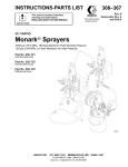
1
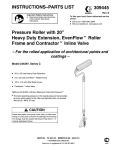
Instructions
Pole Gun with CleanShot™ Shut-Off
Valve and Contractort In-line Valve
312476B
- For the application of architectural paints and coatings 3600 psi (248 bar, 24.8 MPa) Maximum Working Pressure
Important Safety Instructions
Read all warnings and instructions in this
manual. Save these instructions.
Model 289386, Series A (North America)
With 3--ft (0.9 m) extension (244163)
WARNING: HIGH PRESSURE.
Keep Clear of Nozzle.
Read these instructions carefully.
ti10698a
GRACO INC. P.O. BOX 1441 MINNEAPOLIS, MN 55440- 1441
Copyright 2002, Graco Inc. is registered to I.S. EN ISO 9001
Symbols
Warning Symbol
Caution Symbol
WARNING
CAUTION
This symbol alerts you to the possibility of serious
injury or death if you do not follow the instructions.
This symbol alerts you to the possibility of damage to
or destruction of equipment if you do not follow the
instructions.
The wallet-sized warning card provided with this pole gun should be kept with the operator at all times. The card
contains important treatment information should a fluid injection injury occur. Additional cards are available at no
charge from Graco Inc.
WARNING
SKIN INJECTION HAZARD
Spray from the spray tip, hose leaks or ruptured components can inject fluid into your body and cause
extremely serious injury, including the need for amputation. Splashing fluid in the eyes or on the skin
can also cause can also cause serious injury.
D Fluid injected into the skin might look like just a cut, but it is a serious injury. Get immediate
surgical treatment.
D Do not point the spray tip at anyone or any part of the body.
D Do not put hand or fingers over the spray tip, and do not stop or deflect fluid leaks with your hand,
body, glove or rag.
D Do not “blow back” fluid; this is not an air spray system.
D Always have the tip guard and the trigger guard on the in-line valve when spraying.
D Be sure the trigger safety lever operates before operating the in-line valve.
D Lock the trigger safety lever when you stop spraying.
D Follow the Pressure Relief Procedure on page 4 when you are instructed to relieve pressure;
stop spraying; check, clean, or service any system equipment; or install or change spray tips.
D Tighten all fluid connections before each use.
D Check the hoses, tubes and couplings daily. Replace worn or damaged parts immediately. Permanently coupled hoses cannot be repaired.
D Handle and route hoses and tubes carefully. Keep hoses and tubes away from moving parts and
hot surfaces. Do not use the hoses to pull equipment. Do not expose Graco hoses to temperatures
above 150_F (65_C) or below --40_F (--40_C).
TOXIC FLUID HAZARD
Hazardous fluids or toxic fumes can cause a serious injury or death if the fluid is swallowed or
splashed in the eyes or on the skin or if the fumes are inhaled.
D Know the specific hazards of the fluid you are using.
D Store hazardous fluid in an approved container. Dispose hazardous fluid according to all local,
state and national guidelines.
D Dress appropriately for your application. Wear protective eyewear, noise protection for the ears, a
personal respirator, gloves, and clothing.
RECOIL HAZARD
2
Due to the high pressure fluid emitted, a strong recoil action may occur when you trigger the pole gun.
If you are unprepared, your hand could be forced back toward your body or you could lose your balance and fall, resulting in serious injury.
312476
WARNING
FIRE AND EXPLOSION HAZARD
Improper grounding, poor air ventilation, open flames, or sparks can cause a hazardous condition and
result in fire or explosion and serious injury.
D Ground the equipment and the object being sprayed. See Electrical Grounding on page 5.
D Provide fresh air ventilation to avoid the buildup of flammable fumes from solvent or the fluid being
sprayed.
D Extinguish all the open flames or pilot lights in the spray area.
D Electrically disconnect all the equipment in the spray area.
D Keep the spray area free of debris, including solvent, rags, and gasoline.
D Do not turn on or off any light switch in the spray area while operating or if fumes are present.
D Do not smoke in the spray area.
D Do not operate a gasoline engine in the spray area.
D If there is any static sparking while using the equipment, stop spraying immediately. Identify and
correct the problem.
EQUIPMENT MISUSE HAZARD
INSTRUCTIONS
Equipment misuse can cause the equipment to rupture, malfunction, or start unexpectedly and result
in serious injury.
D This equipment is for professional use only.
D Read all instruction manuals, tags, and labels before operating the equipment.
D Use the equipment only for its intended purpose. If you are uncertain about the usage, call your
distributor.
D Do not alter or modify this equipment. Use only genuine Graco parts and accessories.
D Check the equipment daily. Repair or replace worn or damaged parts immediately.
D Do not exceed the maximum working pressure of the lowest rated system component. This equipment has a 3600 psi (25 MPa, 248 bar) maximum working pressure.
D Route the hoses away from the traffic areas, sharp edges, moving parts, and hot surfaces. Do not
expose Graco hoses to temperatures above 150_F (65_C) or below --40_F (--40_C).
D Do not use the hoses to pull the equipment.
D Use fluids or solvents that are compatible with the equipment wetted parts. See the Technical
Data section of all the equipment manuals. Read the fluid and solvent manufacturer’s warnings.
D Fluid hoses must have spring guards on both ends to protect them from rupture caused by kinks or
bends near the couplings.
D Comply with all applicable local, state and national fire, electrical and other safety regulations.
D Wear hearing protection when operating this equipment.
HAZARD OF USING FLUIDS CONTAINING HALOGENATED HYDROCARBONS
Never use 1,1,1-trichloroethane, methylene chloride, other halogenated hydrocarbon solvents or fluids
containing such solvents in this equipment. Such use could result in a serious chemical reaction, with
the possibility of explosion, which could cause death, serious injury and/or substantial property damage.
Consult your fluid suppliers to ensure that the fluids being used are compatible with aluminum and zinc
parts.
312476
3
Installation
Installation
1. Connect grounded fluid hose to the Contractor
In--line valve.
2. Connect 3--ft extension to in--line valve. Use a
wrench to tighten.
3. Connect the CleanShot Shut--off Valve. Use a
wrench to tighten.
NOTE: Be sure seals (33 and 34) are in place in the
in--line valve and shut--off valve before connecting the
extension. Page 13.
4. Without the spray tip installed, start sprayer; turn
the knob on the CleanShot Shut--Off Valve counter--clockwise to the flush position; flush and prime
according to sprayer instructions.
NOTE: The Contractor In--line valve can be used as
an airless spray gun by attaching a HandTitet Guard
and RACR IV Switch Tip.
4. Rotate the spray valve knob counter--clockwise to
the out/flush position. Fig. 2.
5. Hold metal part of pole gun firmly to side of grounded metal waste container. Trigger in-line valve to
relieve pressure.
6. Put in-line valve trigger safety lever in SAFETY
ON position. Fig. 1.
7. Open pump drain valve to help relieve fluid pressure in pump, hose, and pole gun. Triggering inline valve to relieve pressure may not be sufficient.
Have container ready to catch drainage.
8. Leave drain valve open until you are ready to
spray again.
If you suspect that the spray tip or hose is completely
clogged or that pressure has not been fully relieved
after following the steps above, VERY SLOWLY
loosen the tip guard retaining nut (Fig. 3) or hose end
coupling and relieve pressure gradually, then loosen
completely. Then clear tip or hose obstruction.
9. Install spray tip.
Relieve the pressure
following the Pressure
Relief Procedure below.
5.
Pressure Relief Procedure
WARNING
INJECTION HAZARD
To reduce the risk of serious injury,
including fluid injection, splashing in the
eyes or on skin, or injury from moving
parts, always follow this procedure when you stop
spraying; check or service any part of spray
system; or install, clean, or change the spray tip.
1. Put in-line valve trigger safety lever in SAFETY
ON position. Fig. 1.
2. Shut off power supply to pump. Open all air bleed
valves in system.
3. Put in-line valve trigger safety lever in SAFETY
OFF position. Fig. 1.
4
312476
Required Accessories
WARNING
INJECTION HAZARD
Your spray system must have a bleedtype master air valve and a fluid drain
valve. They help reduce the risk of serious injury, including fluid injection, splashing in the
eyes or on the skin, or injury from moving parts, if
you are adjusting or repairing the pump or pole
gun.
D The bleed-type master air valve (air-powered
pumps only) relieves air trapped between the valve
and pump after the air regulator is shut off.
Trapped air can cause the pump to cycle unexpectedly.
D The fluid drain valve assists in relieving fluid pressure in the displacement pump, hose and pole gun.
Triggering the in-line valve to relieve pressure may
not be sufficient.
Installation
Electrical Grounding
WARNING
FIRE AND EXPLOSION HAZARD
Improper grounding could cause static
sparking, which could cause a fire or
explosion. To reduce the risk of property
damage or serious injury, follow the
grounding instructions below.
D Read and follow the warnings in Fire and
Explosion Hazard on page 3.
D Provide electrical grounding continuity throughout
the entire spray system as instructed below.
D Have a trained and qualified person perform all
electrical wiring.
D Comply with all applicable local, state, and
national fire, electrical, and other regulations.
The following grounding instructions are minimum requirements for a system. Your system may include other equipment or objects that must be grounded. Check your local
electrical code for detailed grounding instructions for your
area and type of equipment. Your system must be connected
to a true earth ground.
D Ground the pump or sprayer as instructed in its
separate manual.
D Ground the air compressor or hydraulic power
supply according to the local electrical code and
the manufacturer’s recommendations.
D Use electrically conductive fluid hoses with a
maximum combined hose length of 500 feet (150
m) to ensure grounding continuity.
D Ground the pole gun by connecting it to a properly
grounded fluid hose and pump or sprayer.
D Ground the fluid supply container, object being
sprayed, all solvent pails used when flushing
according to the local electrical code. Use only
metal pails, which are conductive. Do not place the
pail on a non-conductive surface, such as paper or
cardboard, which interrupts the grounding continuity.
D To maintain grounding continuity when flushing or relieving pressure, always hold a metal
part of the pole gun firmly to the side of a grounded
metal pail, then trigger the in-line valve.
312476
5
Operation
Startup
WARNING
INJECTION HAZARD
To reduce the risk of a fluid injection
injury, do not operate the pole gun with
the tip guard or trigger guard removed.
1. Start pump. Adjust fluid pressure so spray is
completely atomized. Always use lowest pressure
that gets desired results. Higher pressure may not
improve spray pattern and causes premature tip
and pump wear.
NOTE: The spray tip orifice size and spray angle
determine the coverage and size of the pattern.
When more coverage is needed, use a larger
spray tip rather than increasing the fluid pressure.
In-Line Gun Trigger Safety Lever
For SAFETY ON position, rotate trigger safety lever so
it is in line with trigger. For SAFETY OFF position, flip
safety lever so it is 90_ to trigger. Fig. 1.
NOTE: In the SAFETY ON position the lever sits in a
detent which holds it in place.
Fig. 1
SAFETY ON
SAFETY OFF
Using the CleanShot Shut--Off Valve
The CleanShot Shut--Off Valve provides two settings:
SPRAY and FLUSH. The valve is factory set to the
SPRAY position for spraying at pressures above 700
psi (4.8 MPa, 48 bar). Rotate the valve knob counter-clockwise to the FLUSH position for flushing, cleaning,
priming and relieving pressure. The FLUSH position is
also used for low pressure spraying applications below
1000 psi (6.9 MPa, 69 bar). Fig. 2.
TI0687
Fig. 2
6
312476
2.
If adjusting the pressure
does not give a good spray
pattern, try another size tip.
Relieve the pressure
before you change the
spray tip.
3. Use full-open, full-close trigger action. Hold tip at a
right angle to the work surface, about 14 inches
(350 mm) away. Do not swing pole gun in arcs.
Practice to find the best length and speed of
stroke.
Operation
Changing Spray Pattern Orientation
WARNING
To reduce the risk of a fluid injection injury, never
spray without the tip guard.
Clearing a Clogged Spray Tip
Frequently during the job and at the end of each
workday, relieve the pressure and manually clean the
tip with a solvent-soaked brush. Frequent cleaning
helps keep fluid buildup from drying and clogging the
spray tip.
The orientation of the tip guard indicates the orientation of the spray pattern.
1. Put in-line gun trigger safety lever in SAFETY ON
position. Fig. 1.
2. Turn the tip guard by hand to change the orientation. Fig. 3.
NOTE: You may have to loosen the retaining nut
to turn the tip guard by hand.
ti10700a
Fig. 4
Use the Reversible Spray Tip to quickly clear clogs as
follows:
1. Put in-line gun trigger safety lever in SAFETY ON
position. Fig. 1.
2. Rotate arrow-shaped handle (Fig. 4) to UNCLOG
position.
3. Put in-line valve trigger safety lever in SAFETY
OFF position, and trigger in-line valve into pail or
onto ground to remove clog. Fig. 1.
4. Put in-line valve trigger safety lever in SAFETY
ON position (Fig. 1), and rotate arrow-shaped handle (Fig. 4) to SPRAY position.
retaining
nut
tip guard
ti10699a
If spray tip is still clogged, relieve the pressure by
following the Pressure Relief Procedure on page 4
and manually clean it. To reduce tip clogs, strain the
fluid you are spraying.
WARNING
Spraying a
vertical band
Spraying a
horizontal band
Fig. 3
INJECTION HAZARD
To reduce risk of an injection or
splashing fluid in eyes or on skin, follow
these precautions before you remove,
clean, or change a spray tip or tip guard.
D Do not hold your hand, body, or rag in front of
spray tip when cleaning or checking clogged tip.
CAUTION
The openings in the tip guard are designed to
reduce paint buildup on the guard while spraying.
Any damage to the sharp edges of the openings
causes paint to collect at that area. To avoid
damaging the tip guard, do not hang the pole gun
by the tip guard.
D Always point tip toward ground or into waste
container when checking to see if it is cleared.
D Do not try to “blow back” paint; this is NOT an
air spray system.
D Follow Pressure Relief Procedure on page 4
before you wipe fluid buildup off spray tip,
before you remove tip guard or spray tip, and
whenever you are instructed to relieve the
pressure.
312476
7
Operation
Flushing the CleanShot Shut-- Off Valve
Rotate the spray valve knob counter--clockwise to the
flush position (see Using the CleanShot Shut--Off
Valve on page 6), and follow the Flushing the InLine Gun procedure below.
Flushing the Contractor In-Line Gun
Always flush the in-line valve thoroughly when you
stop spraying for the day and before the fluid being
sprayed can dry or set up in the system.
WARNING
FIRE AND EXPLOSION HAZARD
To reduce the risk of a serious injury
from fluid injection, static sparking, or
splashing fluid in the eyes on or the skin,
follow these precautions when flushing:
D Be sure entire system and flushing pails are
properly grounded. See Electrical Grounding
on page 5.
D Remove spray tip.
D Use lowest possible fluid pressure.
D Maintain firm metal-to-metal contact between
pole gun and pail during flushing.
D Follow the Pressure Relief Procedure on page
4 whenever you are instructed to relieve
pressure.
3. If flushing with water, flush last with a rust inhibitor
or Graco Pump Armor to protect the system from
corrosion.
4. If necessary, disassemble pole gun and clean all
passages thoroughly with a soft-bristled brush.
CAUTION
Do not soak the entire in-line valve in solvent.
Prolonged exposure to solvent can ruin the
packings.
Checking the Gun Diffuser Operation
Check the diffuser operation weekly. The gun/diffuser/
seat (A) breaks up spray and reduces the risk of fluid
injection when the tip is not installed. Perform the test
below. If it fails, replace the entire Needle Kit, Part No.
218070. Diffuser/seats are not sold separately since
the gun will leak if an old needle is used with a new
diffuser/seat.
1. Follow Pressure Relief Procedure on page 4.
2. Remove the tip guard and spray tip.
3. Start the sprayer and adjust it to the lowest pressure.
4. Aim the gun into a grounded metal pail while
holding it firmly to the pail. Trigger the gun. If the
fluid emitted is not diffused into an irregular
stream, replace the entire needle kit immediately.
A
1. Use a solvent that is compatible with wetted parts
of pole gun, rest of system, and material being
sprayed.
2. Follow flushing instructions for your spray system
or pump.
8
312476
Fig. 5
Operation
Cleaning the Filter (Fig. 6)
Clean the filter assembly (5) daily, as follows:
11
1. Follow Pressure Relief Procedure on page 4.
2. Push up on the trigger guard (3) and swing it away
from the trigger (2).
3. Unscrew the gun handle (13) from the housing
(11). Remove the filter and clean it in compatible
solvent.
2
4. Apply lithium--base grease to the threads of the
gun handle (13) and reassemble gun.
5
3
13
Fig. 6
312476
9
Service
Changing the Needle (Fig. 7)
NOTE: Needle (C), diffuser/seat (A), gasket (B) and
locknut (D) must be replaced together. They are included in Repair Kit 218070.
11
A B
C
10
D
2. Install bracket (10) and locknut (D) loosely on
threaded end of needle (C). Squeeze trigger to pull
needle assembly (C) into gun body (11). Tighten
locknut (D) as required to install needle (C).
3. Squeeze trigger while installing gasket (B) and
diffuser/seat (A). Torque diffuser/seat to 26--32
ft--lb (35--43 NSm).
4. If gun handle (13) was removed, hand tighten into
fluid housing (11). It should fit easily.
5. Adjust needle before using gun.
Fig. 7
Disassembly
6. Be sure trigger guard and tip guard are installed
before using gun.
Adjusting the Needle (Fig. 7)
1. Follow Pressure Relief Procedure on page 4.
1. Engage gun safety latch.
2. Remove tip guard assembly.
2. Hold gun with nozzle straight up.
3. Squeeze trigger while unscrewing diffuser/seat (A)
and gasket (B).
4. Remove locknut (D) and bracket (10).
5. Tap rear of gun with a plastic mallet to push needle
assembly out front.
Reassembly
1. Guide threaded end of needle assembly into front
of gun.
10
312476
3. Remove trigger guard (3). (Fig. 6).
4. Hold your finger against trigger with light pressure.
Using a 5/16--in, open--ended wrench, turn locknut
(D) clockwise until you feel trigger depress slightly.
5. Turn adjusting nut 3/4 turn counter--clockwise.
6. Connect fluid hose. Install tip guard and prime the
system. Trigger gun and release it. The fluid flow
should stop immediately. Engage safety latch and
try to trigger gun. No fluid should flow. If the gun
fails either test, relieve pressure, disconnect hose
and readjust needle.
Service
Replacing the Swivel (Fig. 8)
11
Disassembly
1. Follow Pressure Relief Procedure on page 4.
2. Push up on trigger guard (3) and rotate trigger
guard away from trigger (2).
3. Unscrew gun handle (13) from housing (11).
Remove filter (5) and clean in compatible solvent.
2
4. Remove swivel (4), guard retainer (12) and cushion o--ring (14).
5
5. Save guard retainer (12) and cushion o--ring (14).
Reassembly
3
1. Clean internal thread of handle (13).
13
2. Install guard retainer (12), cushion o--ring (14) and
swivel (4).
3. Apply PST pipe seal (included in Swivel Kit
238817) to external thread of swivel (4) that connects to handle (13).
4. Install swivel (4) into handle (13). Torque swivel to
250 in--lb.
12
14
Fig. 8
4
5. Engage trigger guard (3) to retainer guard (12).
312476
11
Notes
12
312476
Parts
Model 289385 CleanShot Shut--Off Valve
Model 244161 Contractor In--line Valve (North America)
Model 244364 Contractor In--line Valve (Europe)
Model 244365 Contractor In--line Valve (Asia)
30
(included in
kit 221515)
32
40/41
31
33
34
Page 14
35
33
34
1
8
19
11
10
5a
20
6
5b
7
3
2
5
5c
13
5d
14
12
ti10697a
4
312476
13
Parts
CleanShot Repair Kit 244162 (31)
31a Torque 26--32 ft-lb
Swivel Repair Kit 244363 (35)
Valve Body Repair Kit 245687 (36)*
31b
31c
31d
31e
35c
36
35d
31f
31g
35a
31h
35b
Torque 55--60 in-lb
31i
33
34
31j Torque 26--32 ft-lb
*36 Valve Body Kit must be purchased separately
31k
ti0947
14
312476
31*
Parts List
Model 289385 CleanShot Shut--Off Valve
Model 244161 Contractor In--line Valve (North America)
Model 244364 Contractor In--line Valve (Europe)
Model 244365 Contractor In--line Valve (Asia)
Ref.
No.
Part No.
Description
1
2
3
4
5n
218070
244193
196869
238817
218131
5a
5b
5c
5d
6n
7
8
10
11
179722
179731
179763
179750
179733
107110
197052
197058
197568
12
13
196828
113409
195788
14
19
20
21Y
23Y
243393
104938
177538
105334
222385
187348
NEEDLE--DIFFUSER/SEAT KIT
TRIGGER, gun, inline
GUARD, trigger
KIT, swivel 1
FLUID FILTER ASSEMBLY
(standard 50 mesh) includes
replacement parts 5a, 5b, 5c, 5d
RETAINER, spring
ELEMENT, strainer
SPRING, compression
RETAINER, spring
SEAL, sleeve
LOCKNUT
ADAPTER, RAC
BRACKET, stem
HOUSING, fluid, locking (North
America/Asia)
HOUSING, fluid (Europe)
RETAINER, guard
HANDLE, gun (North America/
Europe)
HANDLE, gun (Asia)
PACKING, o--ring
STUD, trigger
NUT, lock, hex
WARNING CARD (not shown)
COVER, warning
Qty.
1
1
1
1
1
1
1
1
1
1
1
1
Ref.
No.
30
Part No.
237859
31
244162
31a
31b
31c
31d
31e
31f
31g
31h
31i
31j
31k
32n
221515
33
34
35
162863
120190
244363
35a
35b
35c
35d
36
40D
41D
245687
244163
244164
1
1
1
1
2
2
1
1
Description
Qty.
RAC IV/5 Hand Tite Guard
7/8 in. (22 mm) thread
1
KIT, CleanShot repair
1
includes parts 31a--31k
SEAT, valve
1
GASKET
1
RETAINER, ball
1
DAMPENER, spring
1
SPRING, compression
1
GUIDE, spring
1
SEAL, u--cup
1
PACKING, o--ring
1
RETAINER, u--cup
1
CAP, end, u--cup
1
KNOB, valve
1
TIP, spray, 515 0.015 in. (0.381mm)
orafice; 10--12 in. (254--304.8 mm)
fan
1
GASKET, non--metallic
2
PACKING, o--ring
2
KIT, swivel repair (includes
35a--35d)
1
SWIVEL, inlet assembly
1
NUT, cap
1
PACKING, o--ring
2
PACKING, o--ring
1
KIT, Valve body
1
3--FOOT POLE
1
6--FOOT POLE
1
Y Replacement Danger and Warning labels, tags and cards are
available at no cost.
n Keep these spare parts on hand to reduce down time.
D
Part number provided for reference only. Not available as a replacement part.
312476
15
Technical Data
Maximum fluid working pressure . . . . . . . . . . . . . . . . . . . . . . . . . . . . . . . . . . . . . . . . . . . . . . . . 3600 psi (25 MPa, 248 bar)
Gun fluid inlet size . . . . . . . . . . . . . . . . . . . . . . . . . . . . . . . . . . . . . . . . . . . . . . . . . . . . . . . . . . . . . . . . . . . . . . . . . . . . 1/4 npsm
Gun fluid outlet size . . . . . . . . . . . . . . . . . . . . . . . . . . . . . . . . . . . . . . . . . . . . . . . . . . . . . . . . . . . . . . . . . . . . . . . . . . 7/8--14 unf
CleanShot fluid orifice size . . . . . . . . . . . . . . . . . . . . . . . . . . . . . . . . . . . . . . . . . . . . . . . . . . . . . . . 0.090 in. (3.175 mm) dia.
Inline valve fluid valve orifice size . . . . . . . . . . . . . . . . . . . . . . . . . . . . . . . . . . . . . . . . . . . . . . . . . 0.125 in. (2.286 mm) dia.
Wetted parts . . . . . . . . . . . . . . . . . . . . . . . . . . . . . UHMWPE aluminum, tungsten carbide, stainless steel, PTFE, brass
Maximum material temperature . . . . . . . . . . . . . . . . . . . . . . . . . . . . . . . . . . . . . . . . . . . . . . . . . . . . . . . . . . . . 120_F (50_C)
Weight
Model 287023, 287026, 287028 . . . . . . . . . . . . . . . . . . . . . . . . . . . . . . . . . . . . . . . . . . . . . . . . . . . . . . . . 2.76 lb (1.03 kg)
Model 287024, 287027, 287029 . . . . . . . . . . . . . . . . . . . . . . . . . . . . . . . . . . . . . . . . . . . . . . . . . . . . . . . . . . 3.5 lb (1.3 kg)
Sound data *
Sound pressure level . . . . . . . . . . . . . . . . . . . . . . . . . . . . . . . . . . . . . . . . . . . . . . . . . . . . . . . . . . . . . . . . . . . . . . . 78 dB(A)
Sound power level . . . . . . . . . . . . . . . . . . . . . . . . . . . . . . . . . . . . . . . . . . . . . . . . . . . . . . . . . . . . . . . . . . . . . . . . . . 87 dB(A)
* Measured while spraying waterbase paint -- specific gravity 1.36 through a 517 tip at 3,000 psi (21 MPa, 207 bar)
per ISO 3744. Actual sound levels may vary with length of extension used.
16
312476
Notes
312476
17
Graco Standard Warranty
Graco warrants all equipment manufactured by Graco and bearing its name to be free from defects in material and workmanship on the
date of sale to the original purchaser for use. With the exception of any special, extended, or limited warranty published by Graco,
Graco will, for a period of twelve months from the date of sale, repair or replace any part of the equipment determined by Graco to be
defective. This warranty applies only when the equipment is installed, operated and maintained in accordance with Graco’s written
recommendations.
This warranty does not cover, and Graco shall not be liable for general wear and tear, or any malfunction, damage or wear caused by
faulty installation, misapplication, abrasion, corrosion, inadequate or improper maintenance, negligence, accident, tampering, or substitution of non--Graco component parts. Nor shall Graco be liable for malfunction, damage or wear caused by the incompatibility of
Graco equipment with structures, accessories, equipment or materials not supplied by Graco, or the improper design, manufacture,
installation, operation or maintenance of structures, accessories, equipment or materials not supplied by Graco.
This warranty is conditioned upon the prepaid return of the equipment claimed to be defective to an authorized Graco distributor for
verification of the claimed defect. If the claimed defect is verified, Graco will repair or replace free of charge any defective parts. The
equipment will be returned to the original purchaser transportation prepaid. If inspection of the equipment does not disclose any defect
in material or workmanship, repairs will be made at a reasonable charge, which charges may include the costs of parts, labor, and
transportation.
THIS WARRANTY IS EXCLUSIVE, AND IS IN LIEU OF ANY OTHER WARRANTIES, EXPRESS OR IMPLIED, INCLUDING BUT
NOT LIMITED TO WARRANTY OF MERCHANTABILITY OR WARRANTY OF FITNESS FOR A PARTICULAR PURPOSE.
Graco’s sole obligation and buyer’s sole remedy for any breach of warranty shall be as set forth above. The buyer agrees that no other
remedy (including, but not limited to, incidental or consequential damages for lost profits, lost sales, injury to person or property, or any
other incidental or consequential loss) shall be available. Any action for breach of warranty must be brought within two (2) years of the
date of sale.
Graco makes no warranty, and disclaims all implied warranties of merchantability and fitness for a particular purpose in connection
with accessories, equipment, materials or components sold but not manufactured by Graco. These items sold, but not manufactured
by Graco (such as electric motors, switches, hose, etc.), are subject to the warranty, if any, of their manufacturer. Graco will provide
purchaser with reasonable assistance in making any claim for breach of these warranties.
In no event will Graco be liable for indirect, incidental, special or consequential damages resulting from Graco supplying equipment
hereunder, or the furnishing, performance, or use of any products or other goods sold hereto, whether due to a breach of contract,
breach of warranty, the negligence of Graco, or otherwise.
FOR GRACO CANADA CUSTOMERS
The parties acknowledge that they have required that the present document, as well as all documents, notices and legal proceedings
entered into, given or instituted pursuant hereto or relating directly or indirectly hereto, be drawn up in English. Les parties reconnaissent avoir convenu que la rédaction du présente document sera en Anglais, ainsi que tous documents, avis et procédures judiciaires
exécutés, donnés ou intentés à la suite de ou en rapport, directement ou indirectement, avec les procedures concernées.
TO PLACE AN ORDER, contact your Graco distributor, or call this number to identify the distributor closest to you:
1--800--690--2894 Toll Free
All written and visual data contained in this document reflect the latest product information available at the time of publication.
Graco reserves the right to make changes at any time without notice.
mm 312476
This manual contains English
Graco Headquarters: Minneapolis
International Offices: Belgium, Korea, China, Japan
GRACO INC.
P.O. BOX 1441
MINNEAPOLIS, MN 55440--1441
www.graco.com
18
312476
Revised 06/2009