1
SERVICE MANUAL
1990
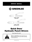
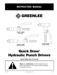
Dieless Hydraulic Crimping Tool
Serial Codes WH and YM
Read and understand all of the instructions and
safety information in this manual before operating
or servicing this tool.
999 8517.9
© 2000 Greenlee Textron
SB 226 REV 5
4/00
1990 Dieless Hydraulic Crimping Tool
Table of Contents
Safety
Description ................................................................... 2
Safety is essential in the use and maintenance of
Greenlee tools and equipment. This manual and any
markings on the tool provide information for avoiding
hazards and unsafe practices related to the use and
maintenance of this tool. Observe all of the safety
information provided.
Safety ........................................................................... 2
Purpose ........................................................................ 2
Other Publications ........................................................ 2
Important Safety Information ........................................ 3
Identification ................................................................. 4
Tools and Supplies ....................................................... 5
Purpose
Pressure Check Procedure .......................................... 5
Pressure Adjustment Procedure .................................. 6
This manual is intended to familiarize authorized
Greenlee service center personnel with the safe
operation and maintenance procedures for the following
Greenlee tools:
Pressure Calibration Check ......................................... 7
Air Purging and Oil Filling Procedure ........................... 8
Die Replacement .......................................................... 9
• 1990 Serial Code WH
Disassembly ......................................................... 10–11
• 1990 Serial Code YM
Assembly .............................................................. 12–15
Keep this manual available to all personnel.
Service Tips ............................................................... 15
Replacement manuals are available upon request at no
charge.
Retrofit Kits ................................................................. 16
Troubleshooting ......................................................... 17
are registered trademarks of
Greenlee and
Greenlee Textron.
Illustrations and Parts Lists .................................. 18–25
Dow Corning, Silastic and 732 are registered trademarks of Dow Corning Corporation.
Description
Loctite is a registered trademark of Loctite Corporation.
Univis is a registered trademark of Exxon Corporation.
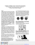
The Greenlee 1990 Dieless Hydraulic Crimping Tool is a
self-contained tool intended to crimp copper and
aluminum compression connectors. A single set of
integral dies provides a wide crimping range.
Other Publications
The Greenlee 1990 is protected by U.S. Patent No.
4,796,461.
Instruction Manuals:
• Serial Code WH: Publication 999 8425.3 (IM-1006)
• Serial Code YM: Publication 999 9994.3 (IM-1093)
KEEP THIS MANUAL
Greenlee Textron / Subsidiary of Textron Inc.
2
4455 Boeing Dr., Rockford, IL 61109-2988 815/397-7070
1990 Dieless Hydraulic Crimping Tool
IMPORTANT SAFETY INFORMATION
SAFETY
ALERT
SYMBOL
Skin injection hazard:
Oil under pressure easily punctures
skin causing serious injury, gangrene or death. If you are injured by
escaping oil, seek medical attention
immediately.
This symbol is used to call your attention to hazards
or unsafe practices which could result in an injury
or property damage. The signal word, defined below,
indicates the severity of the hazard. The message
after the signal word provides information for
preventing or avoiding the hazard.
• Do not use hands to check for
leaks.
• Depressurize the hydraulic
system before servicing.
Immediate hazards which, if not avoided, WILL result
in severe injury or death.
Wear eye protection when operating
or servicing this tool.
Failure to wear eye protection can
result in serious eye injury from
flying debris or hydraulic oil.
Hazards which, if not avoided, COULD result in severe
injury or death.
Hazards or unsafe practices which, if not avoided,
MAY result in injury or property damage.
Pinch points:
Keep hands away from closing dies.
Electric shock hazard:
• This tool is intended for twohanded operation. Maintain a firm
grip on both handles during
operation. Using this tool in any
other manner can result in injury
or property damage.
This tool is not insulated. When
using this unit near energized
electrical lines, use proper personal
protective equipment.
Failure to observe this warning can
result in severe injury or death.
Greenlee Textron / Subsidiary of Textron Inc.
• Do not operate the tool without
dies in place. Damage to the ram
or crimping head may result.
3
1990 Dieless Hydraulic Crimping Tool
Identification
See Retrofit Kits in this manual for an explanation of
interchangeable parts.
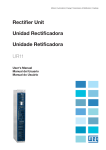
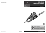
The WH series and YM series crimping tools have
several distinguishing characteristics, which are listed
here. But be aware that, since many parts are interchangeable, a tool sent to you for repair may be a
hybrid — if it has been repaired previously, it may have
a mixture of parts from the WH series and YM series.
Most of the instructions in this service manual apply to
both WH series and YM series. However, some individual steps and some procedures apply to only one or
the other, and are so noted.
1990 Dieless Crimping Tool
7
7
6
6
3
3
1
1
7
6
7
2
4
5
5
6
4
2
3
3
Serial Code WH
Serial Code YM
1. The crimping head is slightly tapered.
1. The crimping head is more steeply tapered.
2. The fixed die is a bolt-on assembly which includes
four bright zinc-plated die plates.
2. The fixed die is one-piece steel casting, colored
black.
3. The two arms on the cylinder each have two
machined slots for the die assembly to engage.
3. The two arms on the cylinder are not slotted.
4. Serial number begins with “WH” prefix.
5. The pump block is covered with a green rubber
coating.
4. Serial number begins with “YM” prefix.
5. The pump block is covered with a black rubber
coating.
6. The handles are one-piece cast aluminum, covered
with green rubber.
6. The handles are bonded assemblies and include
fiberglass inserts.
7. The handle grips have “motorcycle style” ribs.
7. The handle grips are lobed.
Note: The Greenlee 44999 is similar in appearance to these
tools, with some major differences:
• Serial Code is not WH or YM.
• Movable die is yellow.
• Decal on the handle identifies it as a utility tool.
• “44999” is molded into the rubber covering on the block.
For repair instructions for this tool, see Service Bulletin SB 243.
Greenlee Textron / Subsidiary of Textron Inc.
4
1990 Dieless Hydraulic Crimping Tool
Tools and Supplies
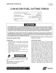
Pressure Check Procedure
Before beginning any repair procedure in this manual,
read the entire section to be sure all of the necessary
tools and supplies are available.
1. Clamp the tool head gently in a vise with the
handles upward. Fully retract the ram.
Tools and supplies for most procedures include:
• Bench vise with jaw protectors to secure the tool
• Quality pressure gauge with 1/2% accuracy and a
range of 0 to 700 Bar (0 to 10,000 psi)
• Gauge adapter:
Serial Code WH: 1/16" NPT male pipe adapter
Serial Code YM: 1/8" SAE straight thread adapter
(Greenlee 36246)
• 32 mm (1-1/4") diameter aluminum rod, at least
76 mm (3") long
• RTV (room-temperature vulcanizing) silicone rubber
adhesive/sealant, such as Dow Corning® Silastic®
732® Multipurpose Sealant
• Pressure Test Kit (Greenlee 32891)
• Exxon Univis® J26 hydraulic oil
2. Remove the RTV (98) and port plug (97).
• Serial Code WH only: dry white lubricant
(silicone or talcum)
3. Install the pressure gauge with the gauge adapter
into the port that the plug (97) was removed from.
4. Pump the handle to fully extend the ram. Note the
pressure required to open the relief valve (which
produces an audible click). The relief pressure
should be 90 to 103 Bar (1300 to 1500 psi).
Tools and supplies for some specific procedures
include:
• C-clamp, arbor press, or other means of retaining the
ram spring when disassembling and assembling the
cylinder
5. Retract the ram and place the 32 mm (1-1/4")
diameter aluminum rod between the dies. Pump the
handle until the relief valve opens. Note the
pressure required to open the relief valve.
The relief pressure should be 566 to 675 Bar
(8200 to 9800 psi).
• Spanner wrench for removing the pressure-adjusting
valve body from the pump block
6. If the crimping tool’s relief pressure is:
• within the ranges stated in Step 4 or Step 5,
remove the gauge and adapter, replace the plug
(97) and reseal with RTV (98). Add hydraulic oil
(see Air Purging and Oil Filling Procedure).
• not within the ranges stated in Step 4 or Step 5,
proceed to the Pressure Adjustment Procedure.
Greenlee Textron / Subsidiary of Textron Inc.
5
1990 Dieless Hydraulic Crimping Tool
Pressure Adjustment Procedure
1. Fully retract the ram, then pump the handle one
stroke.
8. Serial Code WH: Remove RTV (101) and screw
(100).
2. Remove the RTV (16) and set screw (17) from the
fixed handle assembly (18).
9. Loosen fastener (92).
10. Adjust the pressure by turning screw (93) in small
increments. Each 15° of adjustment makes a
difference of approximately 10 Bar (150 psi).
Adjust as follows:
• clockwise to increase relief pressure
• counterclockwise to decrease relief pressure
11. Install reservoir (20).
12. Pump the handle to fully extend the ram. Note the
pressure required to open the relief valve (which
produces an audible click). Repeat the adjustment
procedure until the valve consistently relieves
between 90 and 103 Bar (1300 to 1500 psi).
Vise with
Jaw Protectors
RTV and
Set Screw
(16, 17)
13. Serial Code WH: Tighten the set screw (92). Install
the nylon washer (99) and screw (100).
Serial Code YM: Tighten the jam nut (92).
14. Pump to achieve pressure relief, to ensure that the
adjustment was not disturbed during Step 13.
15. Install the reservoir (20) and O-ring (21).
3. Unscrew the fixed handle assembly (18) from the
tool body.
16. Retract the ram fully.
17. Repeat Step 5 of the Pressure Check Procedure.
4. Pump the handle to fully extend the ram.
18. Remove the gauge and adapter and install the port
plug (97).
5. Remove the plug (19) from the reservoir, taking care
not to spill the oil.
19. Add hydraulic oil to the reservoir until it overflows.
20. Cover the reservoir with a clean shop cloth. Pump
the handle 10 to 12 times, then retract the ram fully.
Repeat several times to eliminate any air in the
system.
21. With the pump handle vertical and the ram fully
retracted, fill the reservoir until it overflows.
Note: The pump handle must be all the way up and
the ram must be fully retracted. Otherwise, you may
overfill the reservoir which will cause it to leak.
Reservoir
Plug (19)
22. Install the reservoir plug (19) and wipe off all excess
oil.
23. Serial Code WH: Coat the reservoir lightly with a
dry white lubricant (silicone or talcum).
24. Pump the handle one stroke and install the reservoir
handle (18). Install the set screw (17) and tighten
securely.
25. Clean the following items, then cover them with an
RTV sealant:
• set screw (17)
• pipe plug (97)
6. Remove the tool from the vise and pour the oil into a
waste oil container.
• screw (100)
7. Clamp to tool head in the vise. Remove O-ring (21)
and reservoir (20). Add oil until the pump block is
3/4 full.
Greenlee Textron / Subsidiary of Textron Inc.
6
1990 Dieless Hydraulic Crimping Tool
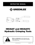
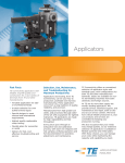
Pressure Calibration Check
To perform this procedure, use Pressure Test Kit 32891.
Check Point (center depression
of the three depression side)
1. Rotate the swivel head fully counterclockwise.
2. Clamp the tool head gently in a vise with the
handles upward.
3. Remove the RTV (98) and port plug (97).
4. Install the pressure gauge with the gauge adapter
into the port that the plug (97) was removed from.
5. Center a new test slug in the dies and pump the
handle. Note the pressure required to open the relief
valve (which produces an audible click).
6. Repeat Step 5 twice, for a total of three slugs.
The relief pressure for every slug should be
214 to 289 Bar (3100 to 4200 psi).
7. Evaluate every test slug with the Go/No Go gauge
as shown.
“Go” Gauge
• If the test slug checkpoint does not fit into GO slot,
the pressure relief valve is set too low.
• If the test slug checkpoint fits into the NO GO slot,
the pressure relief valve is set too high.
• If the test slug checkpoint fits into the GO slot and
does not fit into the NO GO slot, the pressure
relief valve is set correctly.
Greenlee Textron / Subsidiary of Textron Inc.
7
“No Go” Gauge
1990 Dieless Hydraulic Crimping Tool
Air Purging and Oil Filling Procedure
5. Unscrew the reservoir handle from the crimper.
Remove the plug (19) from the reservoir.
Fill the reservoir with Exxon Univis® J26 all temperature
hydraulic oil only.
Do not fill the hydraulic reservoir with any other
type of fluid (such as brake fluid, glycerin, castor
oil, etc.).
Reservoir
Plug (19)
Filling the reservoir with anything other than
hydraulic fluid will damage the tool and void the
warranty.
1. Clamp the tool into a vise with jaw protectors so the
handles are upward, as shown.
6. Retract the ram fully.
7. Add oil until the reservoir overflows.
Vise with Jaw
Protectors
Rubber
Plug (16)
2. Retract the ram by pulling the release trigger back
while pressing down on the handle.
3. Pump the handle one partial stroke.
4. Peel out the rubber plug (16) and remove the set
screw (17) from the reservoir handle (18).
8. Pump the handle several times to advance the ram.
While holding a clean shop cloth over the reservoir,
retract the ram fully. Repeat several times to purge
all of the air from the system.
9. With the pump handle vertical and the ram fully
retracted, fill the reservoir until it overflows.
10. Replace the plug (19) and wipe off excess oil.
Serial Code WH: Coat the reservoir with a dry white
lubricant (silicone or talcum).
11. Pump the handle one stroke and install the reservoir
handle (18). Replace the set screw (17) and tighten
securely.
Remove
Set Screw
(17)
Greenlee Textron / Subsidiary of Textron Inc.
12. Cover the set screw with a silicone rubber sealant,
such as Dow Corning® Silastic® 732® Multipurpose
Sealant.
8
1990 Dieless Hydraulic Crimping Tool
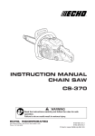
Die Replacement
Movable Die — Either Serial Code
This procedure is divided into two sections — one for
the fixed die (which has some steps that are particular
to the serial code) and one for the movable die (which
includes both serial codes).
1. Remove the fixed die. See Step 1 under Fixed Die.
2. Remove set screw (25) and movable die (26).
3. Install new movable die and set screw.
Fixed Die
4. Install fixed die.
1. Pull the pin (23). Remove one retaining ring (27),
pin (24) and fixed die assembly.
5. Rotate the cylinder fully counterclockwise and fully
retract the ram. Measure the distance between the
outermost blades of the two dies. The distance
should be between 56 and 57.1 mm (2.205" and
2.250"). If the dimension is outside of this range,
remove the set screw (25) and movable die (26):
2. Serial Code WH: Note the positions and alignment
of the two outer die plates and two inner die plates.
Remove the jam nuts (29) and bolts (28). Remove
the die plates (30, 31).
• to increase the distance, remove a spacer (102)
Install new die plates, ensuring that they are located
properly in the appropriate grooves, and that they
are in the proper sequence.
• to decrease the distance, add a spacer (102)
Lower
Radii
Side with
grooves
faces out.
WH
Outer Die Plate
Inner Die Plate
3. Serial Code YM: Transfer the ball detent (22) and
removable pin unit (23) to the new die head. Secure
with pin (24) and retaining ring (27).
• to increase the distance, remove a spacer (102)
• to decrease the distance, add a spacer (102)
2.250"
2.205"
YM
2.250"
2.205"
5. Install the movable die (26) and secure with the set
screw (25).
Greenlee Textron / Subsidiary of Textron Inc.
YM
2.250"
2.205"
6. Install the movable die (26) and secure with the set
screw (25).
4. Rotate the cylinder fully counterclockwise and fully
retract the ram. Measure the distance between the
outermost blades of the movable and fixed dies.
The distance should be between 56 and 57.1 mm
(2.205" and 2.250"). If the dimension is outside of
this range, remove the set screw (25) and movable
die (26) and change the number of spacers as
follows:
WH
2.250"
2.205"
9
1990 Dieless Hydraulic Crimping Tool
Disassembly
3. Pull the cylinder away from the cylinder cap 40 mm
(1-1/2") and remove the rod retaining screw (95).
Remove the driving rod (94).
Before performing any repair procedure:
1. Refer to the Service Tips and Troubleshooting
sections to determine the appropriate service
procedure.
95
2. Read through the entire procedure to be sure that
you have all of the necessary tools, repair parts and
supplies.
95
When performing any service procedure:
1. Check all disassembled parts for wear or damage.
94
2. Visually inspect the ball seats.
3. Carefully replace any O-rings, backup rings, and
other disposable items.
94
WH
4. Check all items for dirt, grit or other contaminants.
YM
4. If the cylinder does not require service, proceed to
Cylinder Cap.
The disassembly procedure is divided into five basic
sections, in this order:
5. Clamp the cylinder assembly in a vise and support
the back of the ram with a C-clamp or arbor press, if
available.
1. Cylinder
2. Cylinder Cap
3. Reservoir
4. Pump Block, Relief Valves, and
Pressure Release Mechanism
5. Pump Pistons
Cylinder
The spring stores at least 310 Newtons (70 pounds)
of force. Follow this procedure exactly as instructed
to release the pressure on the spring carefully.
Failure to observe this precaution will release all of
the energy in the spring at once, resulting in injury
due to flying parts.
6. Loosen the set screw (25) that secures the movable
die (26). Allow the ram to move far enough to
release the tension in the spring.
1. Clamp the pump block in a vise with the handles
downward. Fully retract the ram.
2. Loosen the set screw (96) and unscrew the cylinder
(33) from the cylinder cap (42).
Note: Pull the cylinder straight off of the cap to
prevent damaging the driving rod.
7. Disassemble the C-clamp or arbor press setup.
8. Remove the set screw (25), movable die (26), ram
(38), spring (39), guide (35) and wiper (34).
9. Replace all available packing (O-rings, backup
rings, springs, balls, wiper, etc.).
Greenlee Textron / Subsidiary of Textron Inc.
10
1990 Dieless Hydraulic Crimping Tool
Disassembly (cont’d)
Cylinder Cap — Serial Code WH
4. Use a spanner wrench to remove the pressureadjusting valve body (80) and copper washer (82).
1. Unscrew the driving rod (94) from the stepped rod
(84).
5. Disassemble the low pressure relief.
2. Remove four cap screws and copper washers
(59, 60). Remove the cylinder cap (42).
Serial Code WH: Remove the jam screw, spring,
and ball (79, 78, 77).
3. Inspect various components (43–45, 54, 55).
Replace if worn or damaged.
Serial Code YM: Remove RTV, plug, spring, and
ball (101, 79, 78, 77).
6. Remove one retaining ring (15) and pin (14) from
handle (5). Remove handle assembly.
4. Remove the check ball bushing (58), ball (53) and
spring (57). Inspect the O-ring (56).
7. Unscrew the pressure release body (72). Remove
the ball (74) and spring (73). Remove the shaft (70)
from the body (72). Inspect the O-rings (69, 71) and
replace if worn or damaged.
Cylinder Cap — Serial Code YM
1. Unscrew the driving rod (94) from the stepped rod
(84).
Note: To service the check valves (49, 58) only,
proceed to Step 4.
Serial Code YM: Also remove copper washer (30).
8. Use a T-handle Allen wrench or similar tool to push
the check ball insert (49) out.
2. Remove four cap screws and copper washers
(59, 60). Remove the cylinder cap (42).
Note: The cylinder cap must come straight off.
• Remove ball and spring (47, 48) from the pump
block (46).
3. Inspect various components (43, 44, 54, 55).
Replace if worn or damaged.
• Serial Code WH: Remove roll pin and ball
(52, 51) from the insert (49).
4. Remove the check ball sleeve (58), ball (53), spring
(57), O-rings (29, 56) and backup ring (32).
• Serial Code YM: Remove roll pin and ball (52, 51)
from the body (49).
• Inspect the O-ring (50).
Reservoir
1. Reposition the tool in the vise so that the handles
are upward. Retract the ram by pulling the release
trigger back while pressing down the handle.
Pump Piston
2. Peel out the RTV (16) and remove the set screw
(17) from the reservoir handle (18).
2. Remove cap screws (13) and pivot block (12).
1. Remove one retaining ring (15) and pin (14) from
handle (5). Remove handle assembly.
4. Remove the plug (19) from the reservoir (20).
3. Pull the low pressure plunger (66) upward and out
of the pump block. Check O-rings, quad ring (Serial
Code YM only) and backup rings (62–65), and
replace if worn or damaged.
5. Remove the tool from the vise and pour the oil into
a waste oil container.
4. Use an Allen wrench to unscrew the high-pressure
plunger (68).
6. Remove O-ring (21) and reservoir (20) from the
pump block.
5. Remove the copper washer (67).
3. Unscrew the reservoir handle from the pump block
(46).
6. Use a T-handle Allen wrench or similar tool to push
the check ball insert (49) out.
Pump Block, Relief Valves, and
Pressure Release Mechanism
• Remove ball and spring (47, 48) from the pump
block (46).
1. Serial Code WH: Remove RTV (101), screw (100)
and nylon washer (99). Turn set screw (93) clockwise until it is flush with the relief valve cap (87).
• Remove roll pin and ball (52, 51) from the insert
(49).
• Inspect the O-rings (31, 50).
2. Remove the two machine screws (91) and relief
valve cover (90).
3. Slide out the relief valve cap (87) and remove the
following parts: stepped rod (84), roller guide (83),
adjusting roller (88), two slides (89), valve spring
cap (86), valve spring (85) and relief valve plunger
(81).
Greenlee Textron / Subsidiary of Textron Inc.
11
1990 Dieless Hydraulic Crimping Tool
Assembly
Note: Lubricate all O-rings and backup rings before
assembling.
Pump Block Assembly — Serial Code WH
Perform this procedure with the pump block (46)
secured in the vise with the threaded end downward.
Cylinder
1. Assemble the check ball insert assembly (49) as
follows: Install O-ring (50), 3/16" diameter ball (51),
and roll pin (52). Set this assembly aside.
Note: Roll pin must be below the surface of the
check ball insert. A protruding roll pin will damage
the pump block.
The spring stores at least 310 Newtons (70 pounds)
of force. Follow this procedure exactly as instructed
to contain the spring and its energy.
2. Assemble 3/16" diameter ball (47) and spring
(48) — with small end toward ball — into the pump
block (46). Install check ball insert assembly (49)
into pump block. Insert 1/4" diameter ball (53) into
the check ball insert assembly. Seat each ball in its
hole.
Failure to contain the spring will release all of its
energy, resulting in injury due to flying parts.
1. Install backup ring (37) and O-ring (36) onto ram
(38).
3. Loosen jam screw (61). Assemble O-rings (54–56),
bushing (58) and spring (57) to cylinder cap. Torque
the bushing (58) to 4 Newton-meters (3 foot-pounds).
2. Clamp the cylinder (33) in a vise with the bore
upward. Install wiper and guide (34, 35).
3. Install spring (39) and ram assembly into cylinder
(33). Compress the spring using either an arbor
press or a C-clamp.
4. Set cylinder cap in place on the pump block and
install four copper washers (56) and cap screws
(59). Torque to 27 Newton-meters (20 foot-pounds).
5. Twist jam screw (61) clockwise until set.
Pump Block Assembly — Serial Code YM
Perform this procedure with the pump block (46)
secured in the vise with the threaded end downward.
1. Assemble the check ball insert assembly (49) as
follows: Install O-rings (50, 31), install and seat
3/16" diameter ball (51), and install roll pin (52). Set
this assembly aside.
2. Assemble 3/16" diameter ball (47) and spring
(48) — with small end toward ball — into the pump
block (46). Install check ball insert assembly (49) into
pump block. Insert 1/4" diameter ball (53) into the
check ball insert assembly. Seat each ball in its hole.
3. Assemble the sleeve (58) with O-rings (29, 56),
backup ring (32) and spring (57) to the pump block.
Torque the sleeve (58) to 4 Newton-meters
(3 foot-pounds).
4. Slide the ram die (26) into place. Tighten set screw
(25) securely.
5. Set the assembly aside.
4. Assemble the O-ring (44), backup ring (43) and
copper washers (54, 55) to the cylinder cap (42).
Cylinder Cap Assembly
5. Set cylinder cap in place on the pump block and
install four copper washers (56) and cap screws
(59). Torque to 27 Newton-meters (20 foot-pounds).
1. Install the seal and backup washer (40, 41) into the
cylinder cap (42).
Pump Plunger Assembly
Serial Code WH: Install backup ring (43), O-ring
(44) and retaining ring (45) onto the cylinder cap.
1. Cut 6 mm (1/4") off of backup ring (62) to prevent
overlap. Assemble O-rings and backup rings
(63, 62, 65, 64) to the low-pressure plunger (66).
2. Set the assembly aside.
2. Assemble copper washer (67) and high-pressure
plunger (68) to the pump block. Torque to 24.5 to
27 Newton-meters (18 to 20 foot-pounds).
3. Install low-pressure plunger assembly onto the highpressure plunger assembly.
Greenlee Textron / Subsidiary of Textron Inc.
12
1990 Dieless Hydraulic Crimping Tool
Assembly (cont’d)
Pressure Release Assembly
1. Assemble O-ring (69) to pressure release shaft (70).
Assemble O-ring (71) to pressure release body (72).
5. Tilt the tool so that the roller guide is at the bottom
side. Insert the valve spring (85) and spring cap
(86).
2. Slide shaft assembly into body assembly.
6. Install relief valve cap (87).
Serial Code WH: Screw the set screw (93) into
valve cap until three or four threads are showing
above the surface. Secure it with the jam screw
(92).
Serial Code YM: Set washer (30) into recess in
pump block.
3. Install spring (73) and 9/32" ball (74) into the pump
block.
7. Install the roller (88) in the notch of the roller guide
(83).
4. Assemble pressure release assembly to pump
block. Torque to 8 to 9.25 Newton-meters
(6 to 7 foot-pounds).
8. Insert the two slides (89) into the slot against the
roller and spring cap. See the illustration for proper
orientation. Use care so that the roller remains in its
slot.
Relief Valve/Pressure Control Assembly
1. Assemble low-pressure relief components:
Serial Code WH: Clamp the pump block in the vise
with the threaded end upward. Install ball (77),
spring (78) and jam screw (79). Turn jam screw
clockwise until it is flush with the surface.
92
93
Serial Code YM: Install ball (77), spring (78) and
plug (79) to the side of the pump block.
93
2. Set the pressure-adjusting valve body (80) on a
hard surface. Insert the valve plunger (81) into the
body. Using a punch and hammer, tap the plunger
with a moderate amount of force to seat it in the
body.
Note: Using excessive force will damage the body.
89
3. Install the copper washer (82) and relief valve body
(80) to the pump block. Torque to 27.25 to 32.5
Newton-meters (20 to 24 foot-pounds).
YM
88
Notch
Serial Code YM: Install set screw (93) and secure it
with jam nut (92).
Flat Side
83
Greenlee Textron / Subsidiary of Textron Inc.
88
Notch
9. Install the relief valve cover (90) and adjust it so
that the stepped rod moves freely. Secure the cover
with two machine screws (91).
88
84
89
WH
4. Insert the roller guide (83) into the pump block. Slide
the stepped rod (84) into the roller guide.
92
13
1990 Dieless Hydraulic Crimping Tool
Assembly (cont’d)
Assembly of Cylinder to Cylinder Cap
6. Screw the cylinder assembly (33) into the cylinder
cap until it is fully bottomed. Back the cylinder out to
allow installation of the set screw (96), as follows:
1. Push the stepped rod (84) out until the adjustment
roller (88) drops into the notch in the guide roller
(88), which will produce an audible “click”.
• Do not back the cylinder out more than 180°.
2. Apply a threadlocking compound, such as Loctite®
222 Threadlocker or equivalent, to the threads of
the driving rod (94). Screw the driving rod into the
roller guide (83) until the driving rod just bottoms on
the cylinder cap. This setting is critical to the
proper operation of the tool.
Hint: For ease of assembly, screw the driving rod
clockwise until the flats are aligned as shown.
• There are two tapped holes for the set screw.
Install the set screw in either hole.
• Adjust the set screw (in or out) until the head
rotates 180° freely.
• Do not tighten the set screw.
Pump Handle Assembly
1. Assemble release trigger (2) to pressure release rod
(3) with roll pin (4). Insert into handle (5) and fasten
with roll pin (7).
Serial Code WH: Install trigger stop roll pin (6).
Flat Sides
of 94
2. Assemble the pressure release bar (8) and torsion
spring (9) to the handle with roll pins (10). Glue grip
(11) to handle (5).
3. Mount the lever pivot block (12) to the pump block.
Fasten with two cap screws (13). Torque to
20 Newton-meters (15 foot-pounds).
4. Install the pump handle as follows:
Serial Code WH: Secure the handle to the lever pivot
block (12) and low pressure plunger (66) with two pins
(14). Secure the pins with retaining rings (15).
3. Pull the driving rod out 38 mm (1-1/2").
Note: Pulling the rod out too far will cause the roller
(88) to fall off of the stepped rod. If this happens,
disassemble and start over at Step 1.
Serial Code YM: One pin is permanently mounted
in the handle. Install the handle so this pin engages
the low-pressure plunger (66). Then fasten the
handle to the lever pivot block (12) with the pin (14).
Secure the pin with retaining rings (15).
4. Hook the head of the driving rod (94) into the
groove of the ram (38).
5. Serial Code WH: Assemble the fixed die head. See
the following illustration and the exploded view.
5. Apply a threadlocking compound, such as Loctite®
222 Threadlocker or equivalent, to the threads of
the rod retaining screw (95). Screw the retaining rod
in until it is 0.81 mm (.032") below the back surface
of the ram.
95
Lower
Radii
Side with
grooves
faces out.
95
Outer Die Plate
94
Install the bolts (28) and nuts (29). Torque to
13.5 Newton-meters (10 foot-pounds).
94
WH
Inner Die Plate
6. Serial Code YM: Assemble the detent (22) to the
die head (28).
YM
7. Install the spacer(s) (102) and movable die (26).
Secure by tightening set screw (25).
8. Fasten the fixed die to cylinder with pins (23, 24).
Secure pin (24) with retaining rings (27).
Greenlee Textron / Subsidiary of Textron Inc.
14
1990 Dieless Hydraulic Crimping Tool
Assembly (cont’d)
Service Tips
Final Assembly
• If the hydraulic system has air in it, purge the air and
top off the oil as instructed under Air Purging and Oil
Filling procedure. See Air in the Hydraulic System
at the end of the troubleshooting table.
1. Rotate the cylinder counterclockwise until it stops.
Fully retract the ram.
2. Measure the distance between the outermost
blades of the movable and fixed dies. The distance
should be between 56 and 57.1 mm (2.205" and
2.250"). If the dimension is outside of this range,
remove the set screw (25) and movable die (26)
and change the number of spacers as follows:
• Check valve service requires removal of the cylinder
and cylinder cap. Inspect the ball seats in the pump
block and check body.
• If performing release mechanism service, check for
clearance between the ball (74) and release pin (70).
Inspect the body seat, body seats at the bottom of the
hole, and (Serial Code WH) against the block or
(Serial Code YM) against the copper washer (30).
• to increase the distance, remove a spacer (102)
• to decrease the distance, add a spacer (102)
• Low pressure relief service:
Serial Code WH: Drain and remove reservoir (20).
Remove relief cap (87) to allow access to the spring
retaining screw. Remove screw (79), spring (78) and
ball (77). Inspect parts for contaminants and seat for
damage. Clean and repair.
WH
2.250"
2.205"
YM
Serial Code YM: Remove RTV (101), O-ring plug
(79), spring (78) and ball (77).
2.250"
2.205"
• High pressure relief service: Drain and remove
reservoir (20). Remove relief cap (87) to allow access
to the relief valve and control mechanism. Remove
slides (89), roller (88), spring cap (86) and spring (85).
Remove cone (81). Check torque on the adjusting
body. Reseat cone, clean and assemble.
3. Install the movable die (26) and secure with the set
screw (25).
4. With the tool still in the vise, pour some hydraulic oil
into the pump block. Pump the handle until the ram
is fully extended.
Note: When the ram is fully extended, the handle
resistance will increase and some oil will squirt
back.
• Pump piston O-rings: Remove retaining rings (15)
from pins (14) and remove handle unit from pump
block (46). Remove the two cap screws (13) and pivot
block (12). Pull the low pressure plunger (66) upward
and out of the pump block. Check O-rings and backup
rings (62–65), and replace if worn or damaged.
5. Install reservoir (20) and O-ring (21). Retract the
ram and purge air from the tool. Add oil until reservoir overflows. Wipe off the excess oil.
• The pump handle can be disassembled by removing
the front pin and pivoting the handle up and beyond
the normal stroke.
6. Proceed to calibrate the tool. See the Pressure
Adjustment Procedure.
Greenlee Textron / Subsidiary of Textron Inc.
15
1990 Dieless Hydraulic Crimping Tool
Retrofit Kits
Many components are interchangeable between the
older (WH) and current (YM) crimping tools. However,
some components are not interchangeable, requiring
Crimping Tool
Part
the replacement of several components at once.
Use this table to select the appropriate repair kit.
Purchase
Repair Kit
Explanation
Relief valve cap (87)
or cover (90)
36150
Repair kit includes cap, cover, nut and screw (87, 90, 92, 93).
Crimping head
components or
cylinder (33)
36149
Failure of either pin will overstress the other components, requiring
complete replacement of the crimping head.
Repair kit includes pins, YM-type fixed die and cylinder
(23, 24, 28, 33). This kit is compatible with WH-style tools also.
The pins, dies and cylinder are not individually interchangeable
between the WH and YM series.
Whenever the cylinder is serviced, replacement of the following
is recommended: wiper, guide, O-ring and backup ring
(34, 35, 36, 37).
Cylinder cap (42) or
pump block (46)
36153
Requires complete rebuild. Repair kit includes a YM-style pump
block and all related components, as follows:
(29–32, 40–55, 57, 58, 60, 62, 64, 65, 67, 69, 70, 77, 79,
82, 87, 90, 92–94)
Pump handle
assembly (with grip)
36152
Repair kit includes the following:
(2–5, 7–11, 14, 15, 103)
This kit includes a pressure release rod (3) and pressure release bar
(8). When installing this YM-type kit onto a WH-type tool, you must
retain the WH-type pressure release rod (3) and pressure release
bar (8). They are not interchangeable.
The grips are not interchangeable. When replacing either handle
assembly, you might consider replacing both of them so that two
grips are similar in appearance.
Reservoir handle
assembly (with grip)
36151
Repair kit includes grip and handle (1, 18).
The grips are not interchangeable. When replacing either handle
assembly, you might consider replacing both of them so that two
grips are similar in appearance.
Greenlee Textron / Subsidiary of Textron Inc.
16
1990 Dieless Hydraulic Crimping Tool
Troubleshooting
This table lists some of the most common problems
(first column). The probable trouble areas (second
column) contain numbers in brackets { } relating to the
Problem
Ram advance:
1. no advance
2. slow advance
3. partial retract with each stroke
4. erratic advance
Slow pressure buildup:
1. Handle springs back
2. No handle response
Tool does not achieve high pressure
Ram does not retract
Ram retracts partially
problems listed in the first column. Recommended
service procedures are provided (third column).
Probable Trouble Area
A. Air in hydraulic system {1, 2, 3, 4}
Recommended Service
D. Low pressure relief {1, 2}
E. High pressure relief {1, 2}
F. Plunger O-rings {4}
A. See Air in the Hydraulic System at the end
of this troubleshooting table.
B. Reseat balls; tighten lock screw.
C. Replace O-rings, check ball/pin clearance and
reseat (69–73).
D. Reseat ball (77).
E. Reseat cone (81).
F. Replace O-rings (62–68).
A.
B.
C.
D.
A.
B.
C.
Discharge check ball {1}
Check balls/body {1, 2}
High pressure relief {1}
Release mechanism {1, 2}
Check valves/body
High pressure relief is not seated
Pressure control mechanism is
improperly assembled
A. Wedged connector
B. Die jammed due to misuse
A.
B.
C.
D.
A.
B.
C.
C.
D.
A.
B.
C.
D.
A.
B.
B. Check valve/body {1, 2, 3}
C. Release mechanism {1, 2}
Release mechanism
Bent driving rod
Too much hydraulic fluid
Air in hydraulic system
C. Internal parts bind
C.
D. Dies bind
Pressure setting:
1. does not change as ram advances A. Pressure adjusting screw is loose {1, 3}
2. does not change when adjusting
B. Improper assembly {1, 2}
screw setting is changed
3. does not hold adjustment
C. Stepped rod turned {1}.
D. Spring cap missing {1, 2}
E. Valve cap not tight {1, 2, 3}
F. Driving rod disconnected {1, 3}
Internal leak at:
1. low pressure relief
A. Ball/cone seat damage {1, 2}
2. high pressure relief
B. Dirt or grit in the hydraulic system {1, 2}
3. stepped rod seals
C. Missing or damaged components
D. Damaged O-ring {3}
External leak at:
1. base of reservoir handle
A. Damaged reservoir {1, 2, 3}
2. grip
B. Damaged or missing O-ring at reservoir {1, 2, 3}
3. inside reservoir handle
C. Reservoir plug damaged or missing {1, 2, 3}
4. around release plunger
D. O-ring on plunger damaged or missing {4}
5. between pump block and
E. Loose cylinder cap {5}
cylinder cap
F. O-rings (WH) or copper washers (YM) damaged {5}
6. around cylinder near cap
G. Damaged cylinder seal in cap {6}
7. movable die
H. Damaged O-rings and backup ring on ram {7}
I. Damaged ram {7}
Air in the Hydraulic System
A. Improper fill and purge procedure
B. Loose or missing reservoir plug
C. Damaged O-ring on low pressure plunger
D. Damaged reservoir
E. Damaged or missing O-ring on reservoir
F. Reservoir is underfilled
Greenlee Textron / Subsidiary of Textron Inc.
A.
B.
17
D.
Reseat ball.
Reseat balls.
Reseat and reassemble.
Check clearance and seat body.
Replace O-ring, reseat check balls.
Reseat relief.
Check the assembly of roller, slides, stepped
rod and adjusting screw (80–86, 88, 89).
Free and remove connector.
Free die. Inspect tool and replace any
damaged parts.
Make sure ball is not over-traveling.
Replace rod (94).
Bleed off excess oil.
See Air in the Hydraulic System at the end
of this troubleshooting table.
Check stepped rod and driving rod for a bind
point (84, 94).
Replace dies.
A. Adjust pressure and tighten screw (92, 93).
B. Check the assembly of stepped rod and
roller slides (84, 89).
C. Turn to position. Adjust pressure.
D. Replace cap (86) and adjust pressure.
E. Tighten cap (87) and adjust pressure.
F. Assemble. Fasten with threadlocking compound.
A.
B.
C.
D.
Reseat or replace.
Drain oil; clean parts. Fill with fresh oil.
Rebuild tool.
Replace O-ring and backup ring.
A.
B.
C.
D.
E.
F.
G.
H.
I.
A.
B.
C.
D.
E.
F.
Replace reservoir (20).
Replace O-ring (21).
Replace reservoir plug (19).
Replace O-ring and backup ring (64, 65).
Tighten screws (59) to proper torque.
Replace components (43, 44, 45) or (60).
Replace O-ring and backup ring (40, 41)
Replace O-ring and backup ring (36, 37).
Replace ram. Check cylinder bore for damage.
Fill reservoir and purge air.
Replace plug, or install plug properly.
Replace O-ring and backup ring.
Replace reservoir.
Replace O-ring.
Fill reservoir and purge air.
1990 Dieless Hydraulic Crimping Tool
Illustration — Serial Code WH
9
8
15
10
103
10
14
66
63
62
65
7
64
72
6
71
70
5
21
3
69
74
73
67
12
13
100
4
101 RTV
20
99
2
19
77
78
18
1
68
79
97
85
17 16 RTV
86
46
82
89
80
88
81
93
92
83
84
87
104
91
Greenlee Textron / Subsidiary of Textron Inc.
90
18
98 RTV
1990 Dieless Hydraulic Crimping Tool
11
41
40
59
45
44
43
42
60
61
54
52
58
96
53
34
55
51
35
56
49
57
47
39
50
48
38
95
30 (outer)
94
36
37
31
29
30 (inner)
32
30 (inner)
31
30 (outer)
27
26
25
102
28
24
27
23
33
Greenlee Textron / Subsidiary of Textron Inc.
22
19
1990 Dieless Hydraulic Crimping Tool
Parts List — Serial Code WH
▲◗◆
▲◗
▲◗
▲◗
▲◗
▲◗
▲◗
▲◗
▲◗✓
▲◗
▲◗
▲
▲✓
✓
◆
✓
✓
✓
✓
✓
✓
▼✓
▼✓
▼
▼✓
▼✓
▼✓
▼
▼✓
▼✓
▼
▼✓
▼✓
▼✓
▼✓
▼✓
▼✓
▼✓
▼✓
▼
▼✓
▼✓
▼✓
▼✓
▼✓
▼✓
KEY
1*
2
3
4
5*
6
7
8
9
10
11
12
13
14
15
16
17
18*
19
20
21
22
23
24
25
26
27
28
29
30*
31*
32*
33*
34
35
36
37
38
39
40
41
42
43
44
45
46*
47
48
49
50
51
52
53
54
55
56
57
58
59
60
61
62
63
64
65
UPC NO.
78-331032532
03427
32511
50458
32495
52482
50420
32510
03334
53475
32690
32493
51265
03418
51773
PART NO.
503 2532.9
500 3427.8
503 2511.6
905 0458.5
503 2495.0
905 2482.9
905 0420.8
503 2510.8
500 3334.4
905 3475.1
503 2690.2
503 2493.4
905 1265.0
500 3418.9
905 1773.3
51241
32496
32488
32530
53814
53599
32518
32517
52338
32514
51379
32515
53478
33015
32499
32516
32491
53464
35651
50888
50889
32509
32519
53473
53470
32508
53480
50722
51382
32691
50678
16141
32529
53688
50678
51204
50679
51046
53469
51215
10761
32590
50581
32535
53474
50883
53689
50394
51272
905 1241.3
503 2496.9
503 2488.8
503 2530.2
905 3814.5
905 3599.5
503 2518.3
503 2517.5
905 2338.5
503 2514.0
905 1379.7
503 2515.9
905 3478.6
503 3015.2
503 2499.3
503 2516.7
503 2491.8
905 3464.6
503 5651.8
905 0888.2
905 0889.0
503 2509.4
503 2519.1
905 3473.5
905 3470.0
503 2508.6
905 3480.8
905 0722.3
905 1382.7
503 2691.0
905 0678.2
501 6141.5
503 2529.9
905 3688.6
905 0678.2
905 1204.9
905 0679.0
905 1046.1
905 3469.7
905 1215.4
501 0761.5
503 2590.6
905 0581.6
503 2535.3
905 3474.3
905 0883.1
905 3689.4
905 0394.5
905 1272.3
Greenlee Textron / Subsidiary of Textron Inc.
DESCRIPTION
QTY.
Grip, Handle ................................................................................................ 2
Release Trigger .......................................................................................... 1
Rod, Pressure Release ............................................................................... 1
Roll Pin, .125 x .375" .................................................................................. 1
Lever Unit, Handle ...................................................................................... 1
Roll Pin, .125 x 1.25" .................................................................................. 1
Pin, Release, .125 x 1.00" .......................................................................... 1
Bar, Pressure Release ................................................................................ 1
Spring, Torsion, .187 x .280 x .312" ........................................................... 1
Pin, Roll, .156 x 1.37" ................................................................................. 3
Boot, Pivot Head ......................................................................................... 1
Pivot, Lever ................................................................................................. 1
Screw, Cap, 1/4–20 x .750" Socket Head .................................................. 2
Pin, Fulcrum ................................................................................................ 2
Ring, Retaining, .312" ................................................................................. 2
RTV
Screw, Set, #10–32 x .187" Flat Point Socket ............................................ 1
Handle, Reservoir ....................................................................................... 1
Plug, Bladder, Rubber, Black ...................................................................... 1
Reservoir .................................................................................................... 1
O-ring, 1.47 x 1.71 x .118"–90D ................................................................. 1
Stud, Grooved ............................................................................................. 1
Pin Unit, Removable ................................................................................... 1
Pin, Pivot ..................................................................................................... 1
Screw, Set, #10–32 x .250" Socket ............................................................ 1
Die, Movable ............................................................................................... 1
Retaining Ring, .500" .................................................................................. 2
Bolt, Die Plate ............................................................................................. 2
Nut, Jam, 7/16–20 ...................................................................................... 2
Die Replacement Kit (two inner and two outer die plates) .......................... 1
Plate, Die Support ....................................................................................... 2
Spacer ........................................................................................................ 2
Cylinder ....................................................................................................... 1
Wiper, Ram ................................................................................................. 1
Guide, Ram ................................................................................................. 1
O-ring, 1.62 x 2.00 x .187" Nitrile ................................................................ 1
Backup Ring, Spiral, 1.62 x 1.99 x .033" .................................................... 1
Ram ............................................................................................................ 1
Spring, Compression, 1.49 x 1.82 x 6.06" .................................................. 1
O-ring, 2.37 x 2.56 x .093" .......................................................................... 1
Backup Ring, Single Turn, 2.37 x 2.55 x .050" Teflon ................................ 1
Cap, Cylinder .............................................................................................. 1
Backup Ring, Spiral, .125 x .250 x .049" Teflon ......................................... 1
O-ring, .114 x .250 x .068"–70D Nitrile (same as item 69) ......................... 1
Retaining Ring, .312" .................................................................................. 1
Block, Pump ................................................................................................ 1
Ball, Steel, .187" Diameter, Grade #25 (same as item 51) ......................... 1
Spring, Compression, .194 x .214 x .500" .................................................. 1
Check Ball Insert ......................................................................................... 1
O-Ring ........................................................................................................ 1
Ball, Steel, .187" Diameter, Grade #25 (same as item 47) ........................ 1
Pin, Roll, .062 x .375" ................................................................................. 1
Ball, Steel, .250" Diameter, Grade #25 ....................................................... 1
O-ring, .187 x .312 x .062" Nitrile ................................................................ 1
O-ring, .156 x .281 x .062" .......................................................................... 1
O-ring, .437 x .562 x .062" Nitrile ................................................................ 1
Spring, Compression, .153 x .203 x .440 ................................................... 1
Check Ball Bushing ..................................................................................... 1
Screw, Cap, 1/4–20 x 1.00" Socket Head. ................................................. 4
Washer, Flat, .260 x .390 x .046" Copper ................................................... 4
Screw, Jam Socket ..................................................................................... 1
Backup Ring, Spiral, .375 x .485 x .027" Teflon ......................................... 1
O-ring, .334 x .475 x .070" .......................................................................... 1
O-ring, .750 x 1.00 x .125"–70D Nitrile ....................................................... 1
Backup Ring, Spiral, .750 x .992 x .027" .................................................... 1
20
1990 Dieless Hydraulic Crimping Tool
Parts List — Serial Code WH (cont’d)
UPC NO.
KEY
78-3310PART NO.
DESCRIPTION
QTY.
66
32503
503 2503.5
Plunger, Lo Pressure .................................................................................. 1
▼✓
67
53477
905 3477.8
Washer, Flat, .156 x .250 x .046" Copper ................................................... 1
68
32504
503 2504.3
Plunger, Hi Pressure ................................................................................... 1
▼✓
69
50722
905 0722.3
O-ring, .114 x .250 x .068"–70D Nitrile (same as item 44) ......................... 1
70
32507
503 2507.8
Shaft, Pressure Release ............................................................................. 1
▼✓
71
50168
905 0168.3
O-ring, .364 x .500 x .068"–90D Nitrile ....................................................... 1
72
32506
503 2506.0
Body, Pressure Release ............................................................................. 1
✓
73
32534
503 2534.5
Spring, Compression, .164 x .240 x .750" .................................................. 1
✓
74
50436
905 0436.4
Ball, Steel, .281 Diameter, Grade #25 ........................................................ 1
▼✓
77
50452
905 0452.6
Ball, Steel, .218 Diameter, Grade #25 ........................................................ 1
✓
78
13263
501 3263.6
Spring, Compression, .184 x .242 x .815" .................................................. 1
▼✓
79
51337
905 1337.1
Screw, Jam, 5/16–24 x .156 Socket ........................................................... 1
✖
80
32523
503 2523.0
Body, Pressure-Adjusting Valve ................................................................. 1
✖
81
32789
503 2789.5
Plunger, Valve ............................................................................................ 1
✖▼✓
82
03421
500 3421.9
Washer, Flat, .440 x .687 x .064" Copper ................................................... 1
83
32558
503 2558.2
Guide, Roller ............................................................................................... 1
84
32562
503 2562.0
Rod, Stepped .............................................................................................. 1
✖✓
85
32572
503 2572.8
Spring, Compression, .178 x .322 x .875" .................................................. 1
✖
86
32561
503 2561.2
Cap, Valve Spring ....................................................................................... 1
●▼
87*
32556
503 2556.6
Cap, Relief Valve ........................................................................................ 1
88
32564
503 2564.7
Roller, Valve Adjustment, .197 x .247" ....................................................... 1
89
32559
503 2559.0
Slide, Moving .............................................................................................. 2
●▼
90*
32591
503 2591.4
Cover, Relief Valve ..................................................................................... 1
✓
91
51462
905 1462.9
Screw, Machine, #10–32 x 1.25" Round Head ........................................... 2
●▼✓
92
51286
905 1286.3
Screw, Jam, #8–32 x .109 Socket .............................................................. 1
●▼✓
93
53600
905 3600.2
Screw, Set, 1/4–20 x .437 Flat Point Socket .............................................. 1
▼
94
32563
503 2563.9
Rod Unit, Driving ......................................................................................... 1
95
32557
503 2557.4
Screw, Rod Retaining ................................................................................. 1
✓
96
51245
905 1245.6
Screw, Set, 1/4-20 x .250" Flat Point Socket .............................................. 1
▼
97
50824
905 0824.6
Plug, Pipe, 1/16" ......................................................................................... 1
98
RTV
✓
99
53482
905 3482.4
Washer, Flat, .259 x .393 x .062" Nylon ..................................................... 1
✓
100
53481
905 3481.6
Screw, Cap, 1/4–20 x .250 Fillister Head ................................................... 1
101
RTV
102
33730
503 3730.0
Spacer, .549 x .997 x .025" Stainless Steel ................................................ **
▲
103
35462
503 5462.0
Decal, Warning ........................................................................................... 1
✓
104
22726
502 2726.2
Filter, Oil ..................................................................................................... 1
*No longer available. See the list of kits at the end of this parts list to retrofit the tool.
**Quantity of one or two, if necessary. To determine if this item is necessary, see Die Replacement procedure.
Decals
32792
35463
35757
35758
35759
06233
06243
503 2792.5
503 5463.9
503 5757.3
503 5758.1
503 5759.0
500 6233.6
500 6243.3
Decal, Identification
Decal, Connector Chart
Decal, Instruction
Decal, Pressure Check Procedure
Decal, Safety
Decal, Safety Lid Liner
Decal, Operating Instructions
Accessory
32791
503 2791.7
Case, Carrying
Repair Kits, Retrofit Kits, and Supplies
Replace worn or broken items with newer YM-style components. Some WH-style components are no longer available;
corresponding retrofit kits are marked “Required”.
32891
503 2891.3
Slug Test Kit (includes one Go/No Go Gauge and 30 test slugs)
✓
33013
503 3013.6
Hydraulic Repair Kit
✖
33737
503 3737.8
Relief Valve Repair Kit (Recommended)
◗
35671
503 5671.2
Pump Handle Unit (Required)
●
36150
503 6150.3
Valve Cap and Cover Repair/Retrofit Kit (Required)
◆
36151
503 6151.1
Reservoir Handle Repair/Retrofit Kit (Required)
▲
36152
503 6152.0
Pump Handle Repair/Retrofit Kit (Required)
▼
36153
503 6153.8
Pump Block Repair/Retrofit Kit (Required)
Replace worn or broken components with identical WH-style components:
✓
33013
503 3013.6
Hydraulic Repair Kit
33015
503 3015.2
Die Replacement Kit (includes two inner dies and two outer dies)
Greenlee Textron / Subsidiary of Textron Inc.
21
1990 Dieless Hydraulic Crimping Tool
Illustration — Serial Code YM
10
15
103
9
8
66
Glue grip (11) to handle (5).
7
62
5
72
11
101 RTV
71
79
78
77
70
21
64
63
65
68
67
13
69
74
73
12
30
20
19
85
97 98 RTV
86
1
89
16 RTV
82
80
88
17
81
18
83
84
104
90
91
93
92
Greenlee Textron / Subsidiary of Textron Inc.
46
22
87
1990 Dieless Hydraulic Crimping Tool
3
2
4
15
41
41
40
14
59
42
54
52
60
32
58
53
96
29
51
56
49
47
57
31
55
50
43
44
34
35
48
39
95
38
36
37
94
27
26
28
25
102
23
24
33
Greenlee Textron / Subsidiary of Textron Inc.
22
27
23
1990 Dieless Hydraulic Crimping Tool
Parts List — Serial Code YM
◆
▲◗
▲◗
▲◗
▲◗
▲◗
▲◗
▲◗✓
▲◗
▲◗
▲
▲✓
✓
◆
✓
■
■
■
✓
■✓
■
▼✓
▼✓
▼✓
▼✓
■
✓
✓
✓
▼✓
▼✓
▼
▼✓
▼✓
▼
▼✓
▼✓
▼
▼✓
▼✓
▼✓
▼✓
▼✓
▼✓
▼✓
▼✓
▼
▼✓
▼✓
KEY
1
2
3
4
5
7
8
9
10
11
12
13
14
15
16
17
18
19
20
21
22
23
24
25
26
27
28
29
30
31
32
33
34
35
36
37
38
39
40
41
42
43
44
46
47
48
49
50
51
52
53
54
55
56
57
58
59
60
62
UPC NO.
78-331035689
03427
35698
50458
35672
51048
35697
03334
53475
35688
32493
51265
35676
52336
PART NO.
503 5689.5
500 3427.8
503 5698.4
905 0458.5
503 5672.0
905 1048.8
503 5697.6
500 3334.4
905 3475.1
503 5688.7
503 2493.4
905 1265.0
503 5676.3
905 2336.9
51241
35680
32488
35686
53814
53962
35678
35673
52338
32514
51379
35677
51215
35683
53689
52475
35675
53464
35651
50888
50889
32509
32519
53958
53470
35674
50055
51046
35687
50678
16141
35691
51253
50678
51204
50679
35693
35694
53689
53959
35692
50581
32535
50883
905 1241.3
503 5680.1
503 2488.8
503 5686.0
905 3814.5
905 3962.1
503 5678.0
503 5673.9
905 2338.5
503 2514.0
905 1379.7
503 5677.1
905 1215.4
503 5683.6
905 3689.4
905 2475.6
503 5675.5
905 3464.6
503 5651.8
905 0888.2
905 0889.0
503 2509.4
503 2519.1
905 3958.3
905 3470.0
503 5674.7
905 0055.5
905 1046.1
503 5687.9
905 0678.2
501 6141.5
503 5691.7
905 1253.7
905 0678.2
905 1204.9
905 0679.0
503 5693.3
503 5694.1
905 3689.4
905 3959.1
503 5692.5
905 0581.6
503 2535.3
905 0883.1
Greenlee Textron / Subsidiary of Textron Inc.
DESCRIPTION
QTY.
Grip, Reservoir Handle ............................................................................... 1
Release Trigger .......................................................................................... 1
Rod, Pressure Release ............................................................................... 1
Roll Pin, .125 x .375" .................................................................................. 1
Handle, Pump ............................................................................................. 1
Roll Pin, .125 x .625" .................................................................................. 1
Bar, Pressure Release ................................................................................ 1
Spring, Torsion, .187 x .280 x .312" ........................................................... 1
Pin, Roll, .156 x 1.37" ................................................................................. 2
Grip, Rubber, 1.25 x 1.68 x 6.62" ............................................................... 1
Pivot, Lever ................................................................................................. 1
Screw, Cap, 1/4–20 x .750" Socket Head .................................................. 2
Pin, Fulcrum, .310 x 1.60" .......................................................................... 1
Ring, Retaining, .312" ................................................................................. 2
RTV
Screw, Set, #10–32 x .187" Flat Point Socket ............................................ 1
Handle, Reservoir ....................................................................................... 1
Plug, Bladder, Rubber, Black ...................................................................... 1
Bladder, Reservoir ...................................................................................... 1
O-ring, 1.47 x 1.71 x .118"–90D ................................................................. 1
Detent, Ball ................................................................................................. 1
Pin Unit, Removable ................................................................................... 1
Pin, Pivot, .468 x 2.05" ............................................................................... 1
Screw, Set, #10–32 x .250" Socket ............................................................ 1
Die, Movable ............................................................................................... 1
Retaining Ring, .500" .................................................................................. 2
Head, Die .................................................................................................... 1
O-ring, .437 x .562 x .062" Nitrile ................................................................ 1
Washer, Flat, .343 x .437 x .046" Copper ................................................... 1
O-ring, .334 x .475 x .070" (same as items 56 and 63) .............................. 1
Backup Ring, Spiral, .437 x .562 x .055" .................................................... 1
Cylinder ....................................................................................................... 1
Wiper, Ram ................................................................................................. 1
Guide, Ram ................................................................................................. 1
O-ring, 1.62 x 2.00 x .187" Nitrile ................................................................ 1
Backup Ring, Spiral, 1.62 x 1.99 x .033" .................................................... 1
Ram ............................................................................................................ 1
Spring, Compression, 1.49 x 1.82 x 6.06" .................................................. 1
Seal, 2.562", Quad Ring ............................................................................. 1
Backup Ring, Single Turn, 2.37 x 2.55 x .050" Teflon ................................ 1
Cap, Cylinder .............................................................................................. 1
Backup Ring, Spiral, .187 x .312 x .055" Teflon ......................................... 1
O-ring, .187 x .312 x .062" Nitrile ................................................................ 1
Block, Pump ................................................................................................ 1
Ball, Steel, .187" Diameter, Grade #25 (same as item 51) ......................... 1
Spring, Compression, .194 x .214 x .500" .................................................. 1
Body, Inlet Check ........................................................................................ 1
O-Ring, .218 x .343 x .062" Nitrile .............................................................. 1
Ball, Steel, .187" Diameter, Grade #25 (same as item 47) ......................... 1
Pin, Roll, .062 x .375" ................................................................................. 1
Ball, Steel, .250" Diameter, Grade #25 ....................................................... 1
Washer, Flat, .156 x .281 x .062" Copper ................................................... 1
Washer, Flat, .204 x .375 x .062" Copper ................................................... 1
O-ring, .334 x .475 x .070" (same as items 31 and 63) .............................. 1
Spring, Compression, .188 x .240 x .625" (same as item 78) .................... 1
Sleeve, Check Ball ...................................................................................... 1
Screw, Cap, 1/4-20 x 1.00" Socket Head. .................................................. 4
Washer, Flat, .260 x .390 x .046" Copper ................................................... 4
Backup Ring, Spiral, .375 x .485 x .027" Teflon ......................................... 1
24
1990 Dieless Hydraulic Crimping Tool
Parts List — Serial Code YM (cont’d)
UPC NO.
KEY
78-3310PART NO.
DESCRIPTION
QTY.
▼✓
63
53689
905 3689.4
O-ring, .334 x .475 x .070" (same as items 31 and 56) .............................. 1
▼✓
64
53957
905 3957.5
Seal, 1.00", Quad Ring ............................................................................... 1
▼✓
65
51272
905 1272.3
Backup Ring, Spiral, .750 x .992 x .027" .................................................... 1
66
32503
503 2503.5
Plunger, Lo Pressure .................................................................................. 1
▼✓
67
53477
905 3477.8
Washer, Flat, .156 x .250 x .046" Copper ................................................... 1
68
32504
503 2504.3
Plunger, Hi Pressure ................................................................................... 1
▼✓
69
50722
905 0722.3
O-ring, .114 x .250 x .068"–70D Nitrile ....................................................... 1
70
35690
503 5690.9
Shaft, Pressure Release ............................................................................. 1
▼✓
71
50168
905 0168.3
O-ring, .364 x .500 x .068"–90D Nitrile ....................................................... 1
72
35696
503 5696.8
Body, Pressure Release ............................................................................. 1
✓
73
32534
503 2534.5
Spring, Compression, .164 x .240 x .750" .................................................. 1
✓
74
50436
905 0436.4
Ball, Steel, .281 Diameter, Grade #25 ........................................................ 1
▼✓
77
50452
905 0452.6
Ball, Steel, .218 Diameter, Grade #25 ........................................................ 1
✓
78
53959
905 3959.1
Spring, Compression, .188 x .240 x .625" (same as item 57) .................... 1
▼✓
79
53960
905 3960.5
Plug, O-Ring, 5/16-24 x .380" ..................................................................... 1
✖
80
32523
503 2523.0
Body, Pressure-Adjusting Valve ................................................................. 1
✖
81
32789
503 2789.5
Plunger, Valve ............................................................................................ 1
✖▼✓
82
03421
500 3421.9
Washer, Flat, .440 x .687 x .064" Copper ................................................... 1
83
35699
503 5699.2
Guide, Roller ............................................................................................... 1
84
32562
503 2562.0
Rod, Stepped .............................................................................................. 1
✖✓
85
32572
503 2572.8
Spring, Compression, .178 x .322 x .875" .................................................. 1
✖
86
35695
503 5695.0
Cap, Valve Spring, .343 x .432 x .435" ....................................................... 1
●▼
87
35682
503 5682.8
Cap, Relief Valve ........................................................................................ 1
88
32564
503 2564.7
Roller, Valve Adjustment, .197 x .247" ....................................................... 1
89
32559
503 2559.0
Slide, Moving .............................................................................................. 2
●▼
90
35681
503 5681.0
Plate, Valve ................................................................................................. 1
✓
91
51462
905 1462.9
Screw, Machine, #10–32 x 1.25" Round Head ........................................... 2
●▼✓
92
51686
905 1686.9
Nut, Hex, #10–32 Full ................................................................................. 1
●▼✓
93
53961
905 3961.3
Screw, #10–32, Socket Set ........................................................................ 1
▼
94
35684
503 5684.4
Rod Unit, Driving ......................................................................................... 1
95
32557
503 2557.4
Screw, Rod Retaining ................................................................................. 1
✓
96
51245
905 1245.6
Screw, Set, 1/4-20 x .250" Flat Point Socket .............................................. 1
▼✓
97
53960
905 3960.5
Plug, O-Ring, 5/16-24 x .380" ..................................................................... 1
98
RTV
101
RTV
102
33730
503 3730.0
Spacer, .549 x .997 x .025" Stainless Steel ................................................. *
▲
103
35462
503 5462.0
Decal, Warning ........................................................................................... 1
✓
104
22726
502 2726.2
Filter, Oil ..................................................................................................... 1
*Quantity of one or two, if necessary. To determine if this item is necessary, see Die Replacement procedure.
Decals
32792
35463
06233
06243
503 2792.5
503 5463.9
500 6233.6
500 6243.3
Decal, Identification ....................................................................................
Decal, Connector Chart ..............................................................................
Decal, Safety Lid Liner ................................................................................
Decal, Operating Inst. .................................................................................
Accessory
32791
503 2791.7
Case, Carrying ............................................................................................ 1
503 2891.3
503 3013.6
503 3737.8
503 5671.2
503 6149.0
503 6150.3
503 6151.1
503 6152.0
503 6153.8
Slug Test Kit (includes one Go/No Go Gauge and 30 test slugs)
Hydraulic Repair Kit
Relief Valve Repair Kit
Pump Handle Unit
Cylinder and Die Head Repair Kit
Valve Cap and Cover Repair Kit
Reservoir Handle Repair Kit
Pump Handle Repair Kit
Pump Block Repair Kit
Repair Kits and Supplies
✓
✖
◗
■
●
◆
▲
▼
32891
33013
33737
35671
36149
36150
36151
36152
36153
Greenlee Textron / Subsidiary of Textron Inc.
25
1
1
1
1
Greenlee Textron / Subsidiary of Textron Inc.
4455 Boeing Drive, Rockford, IL 61109-2988 USA
Customer Service (International): 815/397-7070 • Fax: 815/397-9247
Customer Service (North America): 800/435-0786 • Fax: 800/451-2632, 815/397-1865
Canada Fax: 800/524-2853
Printed in the U.S.A.