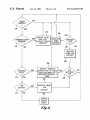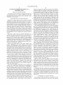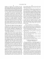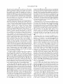
1
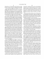
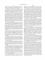
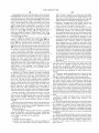
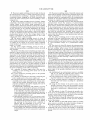
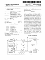
US006223077B1
(12) United States Patent
(10) Patent N0.:
Schweizer et al.
US 6,223,077 B1
(45) Date of Patent:
(54) AUTOMATIC POWER SWITCHING IN A
DEFIBRILLATOR
Apr. 24, 2001
Primary Examiner—George R. Evanlsko
(74) Attorney, Agent, or Firm—Christensen O’Connor
Johnson Kindness PLLC
(75) Inventors: Scott 0. Schweizer, Snohomish; Gus
H. White, Redmond; Aaron Huynh,
(57)
Bothell, all of WA US
ABSTRACT
( )
(73) Assignee: Physio-Control Manufacturing
Corporation, Redmond, WA (Us)
A method and apparatus for providing automatic power
switching in a portable external de?brillator is disclosed.
The power supply switching circuit includes a plurality of
( )
power supply ports for receiving power sources such as
batteries and external power sources. The power supply
Nonce'
Subject to any dlsclalmer’ the term of thls
patent is extended or adjusted under 35
USC' 154 b b 0 d
( ) y
'
switching circuit works with both batteries that include
ays
monitoring devices (smart batteries) and batteries that do not
(21) App1_NO_,09/013,142
include monitoring devices (dumb batteries). The power
(22) Filed:
supply switching circuit also includes microprocessor con
trollable switches for selectively coupling the power supply
(51)
(52)
(58)
Jah- 26’ 1998
Int. c1.7 ..................................................... .. A61N 1/39
US. Cl. ................................................. .. 607/5; 607/29
Field of Search ................................. .. 601/5, 6, 29, 9
(56)
ports to the Output of the power supply Switching Circuit, and
a microprocessor ror oohrrohrhg the Switches and for rhohr'
torrhg the power Supply ports‘ Resident in the rhrcroproces'
sor is a control program for controlling the switching and
References Cited
monitoring operations. The control program uses data
Us PATENT DOCUMENTS
received from the power sources to select the best available
power source to be used as the output for the power supply
switching circuit. The control program has routines for
473237075
4/ 1982 Lang“ -
5,063,928
11/1991 Grevis et al. .
monitoring both smart and dumb batteries, and the power
iiirlrllgrztz :1? iil' '
516113315
supply switching circuit can thus use a combination of smart
3/1997 Cole et a1_ _
5,674,252
5,690,685
and dumb batteries. In one test, a load is placed on a battery
10/1997 Morgan et a1_ _
11/1997 Kroll et a1_ _
5,868,794 *
and then the output voltage of the battery is measured. Auser
of the de?brillator is kept completely informed as to the
2/1999 Barkley etal. ...................... .. 607/29
status of the power sources through information that is
OTHER PUBLICATIONS
provided from a display or auditory signals. For smart
_
Selected Pages from LIFEPAK 11 De?brlllator/Pacemaker
Service Manual, Jan. 1995.
batteries, a fuel gauge is provided on the display. Warnings
are provided when a battery needs changing, or when other
user action is required,
Linear Technology LTC 1479 Data Sheet, 1996.
* cited by examiner
30 Claims, 6 Drawing Sheets
150
-?_> COMMON SYSTEM POWER
S10
BATTERY 20
126i, SERIAL COM
5
40
WT
I08
7
m I 1a
MIL/EFL
12
[16
BATTERY
"2
22
SERIAL
30
g110
r
MICROPROCESSOR
COM
AND
sIIITcII CONTROL
106
814
I
“\l CHARGE [
EXTERNAL
28
(114
34
44
SUPPLY
SERIAL COM
134
24
/
/
rzoj 122/ 124}
128
SERIAL COM
<>_—-
g”
MONITOR
126)
26
SERIAL coAII
8Y5?”
U.S. Patent
Apr. 24, 2001
Sheet 2 0f 6
USER PRESSES SWITCH
US 6,223,077 B1
220
FROM OFF POSITION
PROVIDE SELECTED
200
‘
SOURCE INFORMATION
Y
4
T0 USER
AUXILIARY
SUPPLY ATTACHED
ANB OPERATINC WITHIN
YEs
SELECT AUXILIARY
ACCEPTABLE
PARAMETERS
,
SUPPLY
?
N0
202
VALID
BATTERY POWER
204
BAT. 10
LON AND
YES
SOURCE ABOYE RESERVE
214
YES
BAT. 12 NOT
LOW
LEVEL
0.
g2
NO
206
N0
208
BA T. 12
HAS LOWER
CHARGE
AUTOMATICALLY TURN
YES
LELQEL
OFF DEVICE
N0
210
218
BATTERY 10
YES
FAULT
216
NO
SELECT
BATTERY 10
[150.2
SELECT
BATTERY 12
'
U.S. Patent
Apr. 24, 2001
SMART
BATTERY
US 6,223,077 B1
Sheet 3 0f 6
NO
COMMUNICATION
RECEIVED
'2
220
SMART BATTERY
COMMUNICATE ZERO
CAPACITY AND FAULT
YES
INDICATION
OPERATE AS THOUGH
COMMUNICATION WITH
SMART BATTERY HAS
BEEN LOST BUT
PERIODICALLY RECHECK
TO SEE IF
COMMUNICATION HAS
BEEN RES TORED
3
224
SMART BATTERY
GIVE INDICATION OF
LOW BATTERY
COND‘IPTION
NO
YES
LOW BATTERY
CONDITION DETECTED
3
228
U.S. Patent
Apr. 24, 2001
Sheet 4 0f 6
US 6,223,077 B1
NON-SMART BATTERY IS
BEING MONITORED ( OR
230
SMART BATTERY WITH
NO COMMUNICATION)
234
AFTER
UNIT IS FIRST
POWERED ON AND LOAD
TEST IS RUN, IS BATTERY
VOLTAGE GREATER THAN
OR EQUAL TO 10.5V
AFTER ZOOMS
N0
WITHIN 2 SECONDS LOW
BATTERY DETECTED AND ——>@
DISPLAYED TD USER
k
238
I
NORMAL OPERATION,
IS SENSED BATTERY
VOLTAGE LESS THAN
END OF BATTERY _>®
RESERVE DETECTED
OR EQUAL TO 8.28V
FOR 1 SAMPLE
'2
IS SENSED BATTERY
VOLTAGE LESS THAN OR
EQUAL TO 10.5V + 0'!" —
FOR 1 SECOND
?
YES
5%
U.S. Patent
250
Apr. 24, 2001
Sheet 5 0f 6
US 6,223,077 B1
S)
LOW BATTERY INDICATOR
m
IS ACTIVATED
IS
DEFIBRILLA TOR
TURNED OFF
?
252
N0
YES
1s
POWER
REMOVED FROM
DEFIBRILLA TOR
YES
‘E’
254
NO
LOW BATTERY
VOLTAGE CAUSED
YES
DEFIBRILLATOR TO
TURN OFF
256
NO
HAS
BATTERY BEEN
REMOVED
YES
9
258
262
N0
V
DEFIBRILLATOR
YES
COUPLED TO AC POWER
OR AC POWER THROUGH AN
I
DEACTIVATE LOW
BATTERY INDICATOR
AUXILIARY POWER
SUPPLY
260
[15,21
U.S. Patent
SMART
BATTERY
?
Apr. 24, 2001
Sheet 6 0f 6
NO
\
M
f
K
2 78
COMM UNICA TION
PROBLEM
?
2 72
US 6,223,077 B1
286
PROVIDE ALERT
TONE AND
INDICATE
DISPLAY ”CHECK
BATTERY"
DUMB
BATTERY
NO
INDICATE
DUMB LOW
BATTERY
288
280
DISPLAY "REPLACE
BATTERY”ANO AN ALERT YES
INTERNAL
FAULT
TONE FOLLOWED BY A
REPEATED PRIORITY 3
TONE
282
2
LO W
BA TTERY
YES
INDICATE SMART
LO W
BA TTER Y
292
DISPLA Y
‘
CHARGE
LEVEL
Fig.4
ALL
BATTERIES
LOW
'2
N0
US 6,223,077 B1
1
2
AUTOMATIC POWER SWITCHING IN A
DEFIBRILLATOR
charge the capacitor that provides energy for the de?brilla
tion pulse. While one solution to this problem Would be to
provide sWitches for bypassing a dead battery, this solution
is unacceptable because it drops the voltage of the series
FIELD OF THE INVENTION
batteries by removing the voltage provided by the “dead”
This invention relates generally to methods and apparatus
battery. Even a “dead” battery that is unable to deliver
suf?cient current is usually capable of adding at least some
voltage to the overall level of the series battery circuit. The
for providing poWer to a cardiac de?brillator and, more
speci?cally, to switching betWeen various available cardiac
de?brillator poWer sources.
BACKGROUND OF THE INVENTION
10
15
required to operate a ?brillation detection circuit. In Langer,
the diodes D1 and D2 alloW the necessary current require
ments for the charging circuit to be met by bypassing the
current around a dead battery, While still alloWing the
voltage level from the dead battery to be included in the
circuit for operating the ?brillation detection circuit.
Other implantable de?brillators have attempted to address
the need to generally monitor the life of a de?brillator
battery so that some Warning can be given before the battery
is completely drained. Such a device is shoWn in US. Pat.
20
No. 5,292,348 to SaumareZ et al., Which discloses an
Batteries are often used to poWer portable electronic
de?brillators. Portable de?brillators generate and apply a
high-energy de?brillation pulse to the chest of a patient to
cause the patient’s heart to stop ?brillating and return to a
normal rhythm. The pulses require high energy levels (up to
360 joules) and sometimes multiple de?brillation pulses are
required to restore the patient’s heart to a normal rhythm.
Thus, de?brillators require large amounts of poWer during
normal use. Because of the poWer requirements, portable
external de?brillators generally use special battery packs to
poWer the de?brillator. If the batteries that are being used by
the de?brillator become depleted, the patient cannot be
treated.
The poWer supply needs for portable de?brillators are
distinct from many other portable devices in that the preci
sion and urgency required is much greater, because a
implantable cardioverter/de?brillator and method employ
ing cross-phase spectrum analysis for arrhythmia detection,
25
applied quickly. Thus, it is important that a de?brillator be
able to resolve any poWer supply problems quickly With a
monitoring the battery’s condition. The signal line provides
an end of battery life (EOL) signal to a microprocessor. The
EOL signal is a logic signal Whose status is indicative of the
30
35
batteries. Such de?brillators alloW an operator to sWitch to
describe a device and method for performing automatic
battery maintenance as particularly applied to an implant
sWitches to select one of the alternate poWer sources. Such
able cardioverter de?brillator. Batteries are maintained at a
40
predetermined state of charge by addressing a problem
45
internal to the battery itself, speci?cally that over time
batteries can develop a high internal impedance or equiva
lent series resistance. As described, the voltage, current or
other parameter from the battery is monitored to determine
if the state of charge value is too loW, in Which case a battery
battery maintenance With a gauge or other device. It is
dif?cult in such systems for a user to keep track of Which
poWer source is most appropriate for use and When to sWitch
from one source to another Without affecting unit operation.
One particular problem is that sWitching of the poWer
Within a de?brillator. One such device is shoWn in US. Pat.
No. 5,690,685 to Kroll et al., issued Nov. 25, 1997, Which
discloses an automatic battery-maintaining implantable car
dioverter de?brillator and method for use. Kroll et al.
the backup batteries if the original batteries fail. In the past,
such systems have usually required the user to manually set
systems have also required the user to manually track the
approach of battery failure in the poWer supply.
Still other implantable de?brillators have addressed the
issue of the need to perform automatic battery maintenance
minimum of distraction to the user.
Due to the critical nature of the poWer supply, some
portable de?brillators have been equipped With backup
and also in US. Pat. No. 5,063,928 to Grevis et al., Which
discloses an apparatus and method for detecting and treating
cardiac tachyarrhythmias. Both of these patents shoW a
poWer supply, such as a battery, and a signal line for
patient’s life is often at stake. Urgency is often required
because the chances that a patient’s heart can be successfully
de?brillated increase signi?cantly if a de?brillation pulse is
voltage provided by the dead battery, in addition to the
voltage provided by the good battery(s), are often both
supply in a de?brillator can interrupt critical functions, such
as monitoring of the patient’s heart and the charging of the
loading maintenance cycle is sWitched into activation until
the state of charge value improves.
circuitry in preparation for applying a de?brillation pulse.
Also, many de?brillators have special safety systems that
supply issues that arise for de?brillators, they do not address
While the above devices do address some of the poWer
monitor for out-of-tolerance voltages in the system and
the issues of hoW and When to sWitch to backup poWer
supplies. Neither do they make use of the features of the neW
“smart” batteries that have been developed to provide mea
surements of their oWn internal parameters and thus indicate
trigger a reset When out-of-tolerance voltages occur. Thus,
poWer sWitching in such systems can accidentally trigger the
safety reset of the system.
Some prior implantable de?brillators have attempted to
address some of the poWer supply issues of de?brillators.
One such device is shoWn in US. Pat. No. 4,323,075 to
Langer, Which discloses a method for battery failure com
pensation for a poWer supply used in an implantable de?bril
lator. As shoWn in FIG. 2 of Langer, a pair of batteries B1
and B2 are connected in series to provide the poWer for the
de?brillator circuit. TWo diodes, D1 and D2, are connected
When battery failure is approaching. Nor are they easily
55
upgradable to make use of neW battery technologies as they
develop.
The present invention is directed to providing a method
and apparatus that overcome the foregoing and other disad
vantages. More speci?cally, the present invention is directed
60
to providing a method and apparatus for automatic poWer
sWitching in a portable de?brillator that makes use of the
in parallel With each of the batteries B1 and B2, respectively.
most recently available battery technologies and is easily
As described, one of the problems With the circuit is that if
one of the batteries connected in series goes “dead,” the
current output by the series of batteries is limited by the
output of the dead battery. This presents a serious problem
upgradable.
in a de?brillator Where a high current is often needed to
65
SUMMARY OF THE INVENTION
In accordance With this invention, an automatic poWer
sWitching method and apparatus is provided. The apparatus
US 6,223,077 B1
3
4
comprises an automatic power switching circuit that
includes power supply ports for receiving poWer sources
able to determine When such tests are not need for certain
smart batteries, Which may provide such data Without requir
such as batteries and external poWer sources. The automatic
ing the use of such tests.
poWer sWitching circuit also includes microprocessor con
In accordance With another aspect of the invention, the
microprocessor uses a display and certain auditory tones to
provide information to a user regarding the status of the
trollable sWitches for selectively coupling the poWer supply
ports to the output of the poWer supply. The automatic poWer
sWitching circuit further includes a microprocessor coupled
to the poWer supply ports and sWitches for monitoring the
poWer sources and for selectively controlling the sWitches.
In accordance With one aspect of the invention, the
microprocessor is controlled by a control program. The
poWer sources. Indications are provided When batteries are
in need of maintenance or charging. In addition, a fuel gauge
10
sources according to criteria that are desired for the opera
tion of a portable device such as an external de?brillator.
Thus, a user is kept completely informed as to the status of
control program includes a selection routine for selecting a
poWer supply port receiving poWer from a poWer source to
be coupled to the output of the poWer supply. The selection
routine evaluates data received from the poWer sources, and
evaluates the data according to criteria that are desired for
the operation of an external de?brillator. The selection
routine includes a subroutine suitable for evaluating data
received from smart batteries. Thus, the user need not be
concerned With What the poWer source is and When to
sWitch, as the microprocessor takes care of these consider
may be displayed on the display for smart batteries. Special
routines are provided for testing and monitoring the poWer
15
the poWer sources, and is prompted if action is needed. This
is extremely advantageous in a de?brillator, Where inatten
tiveness or lack of information regarding poWer supply
problems can possibly render a de?brillator inoperable.
In accordance With another aspect of the invention, all of
the poWer sources are sWitched and fused to a single
common system poWer output. This requires feWer unit
ations. Using the control program, the microprocessor is also
Wires carrying large currents. Also, the electronic sWitching
able to perform selection of a poWer source Within a pre
and the use of solid-state sWitches avoids the electrome
chanical failures of manual sWitches that Were used in
determined time frame and With a level of precision that
alloWs smooth and uninterrupted operation of the de?bril
25
lator.
In accordance With another aspect of the invention, the
selection routine also includes a subroutine suitable for
evaluating data received from non-smart or dumb batteries.
This alloWs the poWer supply sWitching circuit to make use
of both smart and non-smart batteries Within a single device.
previous devices.
BRIEF DESCRIPTION OF THE DRAWINGS
The foregoing aspects and many of the attendant advan
tages of this invention Will become more readily appreciated
as the same becomes better understood by reference to the
This is especially advantageous in de?brillators, Where
folloWing detailed description, When taken in conjunction
With the accompanying draWings, Wherein:
special battery packs are often used, and the expense or
non-availability of certain types of battery packs may make
FIG. 1 is a block diagram of an automatic poWer sWitch
ing circuit for use in a portable de?brillator according to the
combined usage a requirement.
35
In accordance With another aspect of the invention, the
control program detects When an external supply is
FIG. 2 is a How chart illustrating the poWer supply
selection method of the present invention;
FIG. 3 is a How chart illustrating a battery monitoring
available, and can use the external supply to poWer the
de?brillator. The microprocessor also coordinates the charg
ing of the batteries With the use of the external supply. Also,
method for a smart battery;
FIG. 4 is a How chart illustrating a battery monitoring
the selection routine of the control program includes a
subroutine suitable for evaluating data received from a smart
method for a non-smart battery;
FIG. 5 is a How chart illustrating a loW battery indicator
external poWer supply. Thus, a portable external de?brillator
can be plugged or unplugged from an external poWer supply,
and batteries can be used and replaced, With automatic
poWer sWitching taking place so as to not affect or interrupt
present invention;
activation and deactivation method; and
45
FIG. 6 is a How chart illustrating a method for generally
displaying information to a user of the device.
critical de?brillator operations. This is especially important
DETAILED DESCRIPTION OF THE
PREFERRED EMBODIMENT
in de?brillators, Where rapid selection and use of the best
available poWer source is critical, and Where improper
sWitching betWeen poWer supplies may cause interruption of
The present invention is a method and apparatus for
critical de?brillator operations. One particular type of criti
cal interruption that may be avoided is the safety reset
providing automatic selection and sWitching betWeen vari
interruption that occurs When out of tolerance voltages are
de?brillator that provides a de?brillation pulse to a patient’s
heart. Portable de?brillators may be poWered by tWo or more
ous available poWer sources, and in particular batteries in a
caused by improper poWer sWitching and thus cause the
system to reset. The safety reset can cause capacitor charg
55
ing and patient monitoring system reinitialiZation delays that
are also thus avoided.
In accordance With another aspect of the invention, one of
the tests for the batteries in the de?brillator consists of
placing a load on them and attempting to draW a relatively
patient both quickly and With enough energy. OtherWise the
patient may be harmed.
Ablock diagram of an automatic poWer sWitching circuit
formed in accordance With the present invention is illus
high current (eg 1 amp). The output voltage of the battery
is then also measured a short time later (eg after 200
milliseconds) to determine if it falls Within a speci?ed range
(e.g. above 10.5 volts for a 12 volt battery). This type of test
is especially important in de?brillators, Where high currents
and consistent voltage levels are needed for consistent and
reliable de?brillator operation. The microprocessor is also
batteries or by an external poWer source, When available.
Rapid selection of the best available poWer source for a
de?brillator With a minimum of distraction to a user is highly
desirable because a de?brillation pulse must be applied to a
65
trated in FIG. 1. The circuit includes tWo batteries 10 and 12,
an external poWer supply 14, and a microprocessor and
sWitch controller 16. As Will be described more fully beloW,
the microprocessor and sWitch controller 16 monitors the
condition of the batteries 10 and 12, and the external supply
US 6,223,077 B1
5
6
14, and uses the resulting data to select one of the power
decision block 202, the input poWer sources are sampled and
supplies as the power supply for the system. The external
poWer supply 14 may not always be available. The nature of
the external poWer supply 14 depends on the type of
de?brillator being used. In a type of de?brillator Which runs
evaluated for acceptable operating parameters. Speci?cally,
the microprocessor and sWitch controller 16 checks to
determine if an external (auxiliary) supply is attached and is
operating Within acceptable parameters. With reference to
the circuitry of FIG. 1, this step is accomplished by the
microprocessor and sWitch controller 16 checking lines 124
primarily off of DC battery poWer, the external poWer supply
may be an external auxiliary supply that provides DC poWer
but is itself poWered by AC. In another type of de?brillator
that runs primarily off of AC poWer With battery backup
poWer, the external poWer supply may be a source such as
a Wall socket that provides AC poWer.
Batteries 10 and 12 each have serial communication ports
20 and 22, respectively. External poWer supply 14 has a
serial communication port 24. External poWer supply 14 is
a “smart” external auxiliary supply that includes monitoring
circuitry to perform measurements regarding the auxiliary
supply’s condition (e.g., voltage and current output
and 126 to determine if an external supply 14 is available.
10
is being carried around, so that batteries 10 and 12 are the
only poWer supplies available.
Returning to FIG. 2, if at decision block 202 the micro
processor 16 determines that an external (auxiliary) supply
15
is available and is operating Within acceptable parameters,
the microprocessor proceeds to a block 204. At block 204,
the microprocessor selects the external (auxiliary) supply as
the de?brillator poWer supply. Thus, if an auxiliary supply is
capacities), and to make the results of the measurements
available to the microprocessor through its serial commu
nication port. Batteries 10 and 12 are “smart batteries,” i.e.,
batteries 10 and 12 are batteries that include monitoring
circuitry to perform internal measurements as to the bat
attached and is operating Within acceptable parameters, it
takes precedence over the other poWer sources and is
selected to poWer the de?brillator. With reference to the
circuitry of FIG. 1, the operation at block 204 is performed
by the microprocessor and sWitch controller 16 closing
tery’s condition (e. g., the battery’s charge capacity, the level
of stored energy, etc.) and make the results of the measure
ments available to the microprocessor through their serial
Although FIG. 1 is shoWn With external supply 14 included,
it may often be disconnected When the portable de?brillator
25
communication ports. These measurements are sometimes
referred to as providing a type of “smart fuel gauge” for the
batteries. While batteries 10 and 12 are smart batteries, as
sWitch 44 such that the output 114 from external poWer
supply 14 is connected to the common system poWer line
150.
Returning to FIG. 2, if at decision block 202 the micro
processor determines that no external (auxiliary) supply is
Will be described beloW, the system is also designed to
attached or, if attached, is not functioning properly, the
obtain and process information from older non-smart or
microprocessor proceeds to a decision block 206. At deci
“dumb” batteries. The serial communication ports 20, 22,
sion block 206, the microprocessor monitors the available
and 24 are coupled through a bus line 126 to a serial
batteries to determine Which batteries have poWer and their
status (as Will be described in more detail beloW With
communication port 26 of the microprocessor and sWitch
controller 16. Thus, microprocessor and sWitch controller 16
is able to monitor the condition of batteries 10 and 12 and
external poWer supply 14 through the information provided
from the serial communication ports 20, 22, and 24, respec
tively. Microprocessor and sWitch controller 16 also
35
includes a serial communication output port 28 for providing
data to the general de?brillator control circuit and display
reserve levels While under a load. While performing this
evaluation, the microprocessor and sWitch controller 16
(not shoWn) through a line 128.
The poWer outputs for batteries 10 and 12 are coupled to
lines 110 and 112, respectively. The poWer output for
external supply 14 is coupled to a line 114. External poWer
supply 14 also includes a port 6 for providing a charging
reference to FIGS. 3—6). With reference to the circuitry of
FIG. 1, the operation at block 206 corresponds to the
microprocessor evaluating batteries 10 and 12 for proper
operating parameters. These operating parameters are based
on the battery’s ability to maintain voltage above minimum
45
output on a line 106 for charging the batteries 10 and 12.
monitors serial communications from serial communication
ports 20 and 22 and/or monitors outputs 110 and 112 to
determine if the batteries 10 and 12 meet the operating
parameters. If the smart batteries 10 and 12 are replaced by
non-smart batteries, the determination of the batteries’ func
tionality is based on the measurements of the outputs 110
Microprocessor and sWitch controller 16 monitors the volt
age on lines 110, 112, and 114 through lines 120, 122, and
124, respectively, connected to a monitor port 17. Thus, in
operating parameter requirements, the microprocessor pro
the case Where non-smart batteries are used in place of smart
softWare of the microprocessor automatically shuts off the
batteries 10 and 12, voltage measurements can still be taken
poWer to the de?brillator.
and 112. If there are no poWer sources available that meet the
ceeds to a block 218. At block 218, the poWer management
by the microprocessor and sWitch controller 16 from the
At block 206, if the microprocessor determines that at
poWer outputs of the batteries on lines 110 and 112.
Output lines 110, 112, and 114 are coupled to lines 130,
132, and 134 through uses 30, 32, and 34, respectively. The
outputs from the poWer sources are fused for ?re safety. The
lines 130, 132, and 134 are coupled through sWitches 40, 42,
and 44, respectively, to a single common system poWer line
150. Preferably, the sWitches are solid state sWitches.
SWitches 40, 42, and 44 are controlled by control lines 140,
142, and 144, respectively, from a selection port 18 in
microprocessor and sWitch controller 16, Microprocessor
and sWitch controller 16 also includes an on/off sWitch 8 that
is controlled by a line 108 from the de?brillator system.
FIG. 2 illustrates the poWer source selection operation of
the automatic poWer sWitching circuit of FIG. 1. As shoWn
at a block 200, the unit is ?rst turned on by a user. At a
least one of the battery poWer sources meets the proper
55
operating parameters, the microprocessor proceeds to a
decision block 208. The series of steps represented by blocks
208, 210, 212, 214, and 216 and described next comprise a
routine run by the microprocessor that results in the selec
tion of one of tWo batteries for use as the poWer source of
the de?brillator. It Will be understood that in a system that
contains more than tWo batteries, similar testing techniques
can be used to select the most appropriate battery.
At decision block 208, the microprocessor determines
Whether the poWer condition of the battery 10 is loW and
Whether the poWer condition of the battery 12 is above loW.
65 For non-smart batteries in a 12-volt system, a loW poWer
condition is determined by measuring the output 110 or 112
of the battery to determine if it falls beloW a selected
US 6,223,077 B1
7
8
threshold (e.g., 10.5 volts). When smart batteries are being
used, the loW power condition is determined by monitoring
With regard to selecting a poWer source and charging the
batteries. The selected battery is fully used until a de?ned
sWitching point is reached. When this occurs, the next
the serial communication from ports 20 and 22 on line 126.
From decision block 208, if battery 10 has a loW poWer
condition While battery 12 does not have a loW poWer
condition, the microprocessor proceeds to a block 214. At
block 214, the microprocessor and sWitch controller 16
selects battery 12 to supply poWer to the de?brillator. With
reference to the circuitry of FIG. 1, the selection of battery
12 at block 214 corresponds to the microprocessor and
sWitch controller 16 closing sWitch 42 and thus connecting
battery is selected. This alloWs complete use of battery
poWer before sWitching, increasing unit operation time and
battery life. As Will be described in more detail beloW, all
sWitching is automatic and is made knoWn to the user
through the system/user interface provided on the display
10
the output 112 to the common system poWerline 150.
If at decision block 208 the microprocessor determines
that the poWer condition of battery 12 is loW or that the
poWer condition of battery 10 is not loW, the microprocessor
device.
The above-described functions of the automatic poWer
sWitching system of the present invention are described in
more detail beloW With reference to FIGS. 3—6. FIGS. 3—5
generally illustrate the internal measurements and determi
15
nations made by the microprocessor and sWitch controller
16, While FIG. 6 generally illustrates the procedures for
proceeds to a decision block 210. At decision block 210, the
displaying information to a user of the device.
microprocessor determines if battery 12 has a loWer charge
level than battery 10. In the preferred embodiment, the status
of the charge level is easily read from smart batteries, as this
is one of the internal measurements they provide. The
microprocessor Will select the battery With the loWer charge
As illustrated in FIG. 3, battery monitoring, such as that
required at block 206 of FIG. 2, begins at point A of FIG. 3.
At a decision block 220, the microprocessor 16 determines
Whether smart battery communication is being received
from a battery that is currently being monitored. If smart
level to be used ?rst. This is done so that the most depleted
battery communication is not being received, the micropro
battery Will be used ?rst, thus alloWing for the most ef?cient
cessor proceeds to a point B, Which Will be described in
more detail beloW With reference to FIG. 4, and if smart
use of the batteries in the system. If at block 210 the
microprocessor determines that the battery 12 has a loWer
25
charge level than battery 10, the microprocessor proceeds to
battery communication is being received, the microproces
sor proceeds to a decision block 222.
block 214 Where battery 12 is selected to poWer the system.
If at block 210 the microprocessor determines that the
battery 12 does not have a loWer charge level than battery
10, the microprocessor proceeds to a decision block 212. At
Whether the smart battery has communicated a Zero capacity
decision block 212, the microprocessor determines Whether
such a communication has not been received, the micropro
battery IO has a fault. A fault condition is communicated by
a smart battery When the smart battery monitoring circuitry
determines that the smart battery has an internal fault.
Alternatively, a fault can be generated from any type of
battery if the path to the battery, such as the fuse or the
sWitch, goes bad or if the battery is unable to support a
charge When tested. An example of a battery unable to
cessor proceeds to a decision block 226.
At decision block 222, the microprocessor determines
or fault indication. If such a communication has been
received, the microprocessor proceeds to a block 224, and if
At block 224, the microprocessor is set to operate as
35
but sets a ?ag to periodically recheck to see if communica
tion from the smart battery has been restored. From block
224, the microprocessor proceeds to point B, Which Will be
described in more detail beloW With reference to FIG. 4.
support a charge Would be 12-volt battery that consistently
At decision block 226, the microprocessor determines
drops to a 5-volt level When a load is placed on it. If battery
10 has a fault, then the microprocessor proceeds to block
214 Where battery 12 is selected to poWer the de?brillator.
If at block 212 the microprocessor determines that battery 10
does not have a fault, the microprocessor selects battery 10
though communication With the smart battery has been lost,
Whether the communication received from the smart battery
gives an indication of a loW battery condition. If a loW
battery condition is indicated, the microprocessor proceeds
to a block 228, and if a loW battery condition is not indicated,
provides selected source information to a user on a display
the microprocessor returns to decision block 220 and battery
monitoring is continued. At block 228, if a loW battery
condition is detected, the microprocessor indicates to the
user that a loW battery condition has been detected and, then,
proceeds to a point C, Which Will be described in more detail
device, Which the microprocessor communicates With via
beloW With reference to FIG. 5.
to poWer the de?brillator.
45
From blocks 204, 214, and 216, the microprocessor
proceeds to a block 220. At block 220, the microprocessor
port 28 and communication line 128. The information about
FIG. 4 illustrates the continuing battery monitoring opera
each of the poWer sources that is displayed to the user is
described in more detail beloW With reference to FIG. 6.
From block 220, the microprocessor returns to decision
block 202 and another pass is made through the poWer
supply selection procedures described above.
tion of FIG. 3, When either a non-smart battery is being
monitored or a smart battery With no communication is
being monitored. As shoWn in FIG. 4, from a point B, the
55
microprocessor continues to a block 230 Which indicates
that a non-smart battery or a smart battery With no commu
An additional feature of the invention is that it coordinates
nication is being monitored. At a decision block 232, the
battery charging With the external supply 14, assuming the
microprocessor determines if the unit has ?rst been poWered
external supply 14 has serial communication capability. In
this regard, the microprocessor and sWitch controller 16
on and, if it is, runs a load test. A suitable load test consists
monitors the status of the batteries 10 and 12 through serial
communication ports 20 and 22 or through measurement
lines 120 and 122 and determines When and hoW long the
batteries should be charged by external supply 14.
In summary, the control program softWare routine of FIG.
2 causes the microprocessor and sWitch controller 16 to
monitor the battery conditions and take appropriate action
65
of placing a 1.5 amp load on each battery for 200 millisec
onds and then checking at the end of 200 milliseconds to see
if the battery voltage is less than or equal to 10.5 volts. This
test is an especially important criterion in a de?brillator due
to the high current and charging requirement that a poWer
source must meet to avoid interruption or delay of critical
de?brillator functions. If the load test is not passed, i.e., the
battery voltage is less than or equal to 10.5 volts, the
US 6,223,077 B1
9
10
microprocessor proceeds to a block 234. If the load test is
microprocessor proceeds to a decision block 236.
At decision block 234, Within a predetermined short
coupled to AC poWer, the microprocessor proceeds to block
262. If the unit is not coupled to AC poWer, the micropro
cessor proceeds to pointA and battery monitoring continues.
FIG. 6 illustrates the general method of displaying to a
period of time, i.e., tWo seconds, a loW battery is detected by
user the various battery conditions and faults that are deter
passed, i.e., the battery voltage is greater than 10.5 volts, the
the microprocessor and a message is displayed to a user. The
mined by the microprocessor. As shoWn in a decision block
microprocessor then proceeds to point C, Which Will be
270, the microprocessor determines that the battery that is
described in more detail beloW With reference to FIG. 5.
being monitored is a smart battery. As described next, if the
At decision block 236, the microprocessor determines
Whether the sensed battery voltage during normal operation
10
after the initial poWer on of the system is less than or equal
to some predetermined value, e.g., 8.28 volts for one sample
period (in the one actual embodiment of the invention, one
sample period is 56 microseconds). If the voltage is less than
the predetermined value, e.g., 8.28 volts, the microprocessor
proceeds to a block 238, and if the voltage is not less than
8.28 volts, the microprocessor proceeds to a decision block
240. At block 238, the microprocessor determines that the
end of battery reserve has been detected for the battery.
Thereafter, the routine proceeds to point A of FIG. 3 and
is a smart battery, the microprocessor proceeds to a decision
15
At decision block 272, the microprocessor determines
Whether there is a communication problem With the smart
battery. If a communication problem eXists, the micropro
20
At decision block 240, the microprocessor determines
25
battery voltage is less than the predetermined value for the
30
continues.
FIG. 5 illustrates the battery monitoring routine as it
continues once a loW battery indication has been determined
by the microprocessor. Continuing from point C, the micro
processor proceeds to block 250 Where a loW battery indi
cator is activated. The loW battery indicator remains acti
40
At a decision block 252, the microprocessor determines if
the de?brillator has been turned off. If the de?brillator has
been turned off, the microprocessor proceeds to a block 262
Where the loW battery indicator is deactivated. If the de?bril
lator has not been turned off, the microprocessor proceeds to
a decision block 254.
At decision block 254, the microprocessor determines if
poWer has been removed from the de?brillator. If poWer has
50
proceeds to block 262. If poWer has not been removed from
the de?brillator, the microprocessor proceeds to a decision
block 256.
At decision block 256, the microprocessor determines if
loW battery voltages have caused the de?brillator to turn off.
If loW battery voltages have caused the de?brillator to turn
55
off, the microprocessor proceeds to block 262. If loW battery
At decision block 260, the microprocessor determines
poWer through an auXiliary poWer supply. If the unit is
as a type of “fuel gauge” that shoWs increasing poWer by
displaying from Zero to four lighted bars. If the smart battery
indicates that it has greater than 75% of its maXimum charge
level, four bars are displayed. If the smart battery indicates
that its charge level is less than or equal to 75% and greater
than 50% of its maXimum charge level, then three bars are
displayed. If the smart battery indicates that its charge level
60
ceeds to a decision block 260.
Whether the de?brillator is coupled to AC poWer or to AC
then proceeds to decision block 284.
At decision block 276, the microprocessor determines
Whether the smart battery has communicated that it has a loW
battery condition. If a loW battery condition has been
communicated, the microprocessor proceeds to a block 282,
and if a loW battery condition has not been indicated, the
microprocessor proceeds to a block 292. At block 282, the
microprocessor causes the display to display a “smart loW
battery” icon. The microprocessor then proceeds to a deci
sion block 290, Which is described beloW.
At block 292, the microprocessor causes the display to
display the charge level of the smart battery. In one actual
embodiment of the invention, the charge level is displayed
voltages have not caused the de?brillator to turn off, the
microprocessor proceeds to a decision block 258.
At decision block 258, the microprocessor determines
Whether the battery has been removed. If the battery has
been removed, the microprocessor proceeds to block 262. If
the battery has not been removed, the microprocessor pro
Whether an internal battery fault has been detected and
communicated by the smart battery. If an internal fault has
been communicated, the microprocessor proceeds to a block
280 and, if an internal fault has not been detected, the
microprocessor proceeds to a decision block 276. At block
280, the microprocessor causes the display to display a
“replace battery” message and the de?brillator to produce an
alert tone. The alert tone is folloWed by another tone
designated a repeated priority 3 tone. The microprocessor
vated until one of the conditions of FIG. 5 is met. The
been removed from the de?brillator, the microprocessor
then proceeds to a decision block 284. Thereafter, the smart
At decision block 274, the microprocessor determines
to block 234. If the sensed battery voltage is not less than the
de?brillator supports a loW battery indicator and message for
an alert tone to be emitted by the de?brillator and the display
to display a “check battery” message. The microprocessor
battery is treated as a non-smart or dumb battery, as
described in more detail beloW.
predetermined period of time, the microprocessor proceeds
each battery.
cessor proceeds to a block 278 and, if a communication
problem does not eXist, the microprocessor proceeds to a
decision block 274. At block 278, the microprocessor causes
Whether the sensed battery voltage during normal operation
predetermined value for the predetermined period of time,
the microprocessor returns to point A and battery monitoring
block 272. If the microprocessor determines that the battery
that is being monitored is not a smart battery, the micropro
cessor proceeds to a decision block 284.
battery monitoring is continued.
is less than or equal to some predetermined value, e.g., 10.5
volts +/— some predetermined percent, e.g., 5% for a pre
determined period of time, e.g., one second. If the sensed
battery is a smart battery, the microprocessor proceeds With
checking the battery for errors through a series of steps prior
to displaying the charge level of the battery. If the micro
processor determines that the battery that is being monitored
65
is less than or equal to 50% but greater than 25% of its
maXimum charge level, then tWo bars are displayed. If the
smart battery indicates that its charge level is less than or
equal to 25% but greater than 0% of its maXimum charge
level, then one bar is displayed. If the smart battery indicates
that its charge level is less than or equal to 0% of its
maXimum charge level, then Zero bars are displayed. From
block 292, the microprocessor returns to decision block 270
and monitoring continues.
US 6,223,077 B1
11
12
As described above, the microprocessor reaches decision
rality of poWer sources are at least one of external
poWer sources or batteries, Wherein said batteries are at
least one of smart batteries or dumb batteries, said
block 284 When the battery is to be evaluated as a non-smart
or dumb battery, or if a smart battery has communication or
smart batteries including monitoring devices, and said
dumb batteries not including monitoring devices;
internal fault problems. At decision block 284, a test is made
to determine if the output voltage of the battery is above or
beloW a predetermined loW battery threshold. If the output
voltage of the battery is determined to be beloW the loW
a plurality of microprocessor controllable sWitches for
battery threshold, the microprocessor proceeds to a block
288 and, if the output of the battery is determined to not be
beloW the loW battery threshold, the microprocessor pro
a microprocessor connected to said plurality of poWer
selectively coupling the poWer supply ports to the
output of the poWer supply sWitching circuit;
supply ports and to said plurality of microprocessor
controllable sWitches, the microprocessor acquiring
data regarding said poWer sources, said microprocessor
ceeds to a block 286. At block 286, the microprocessor
causes the display to display a “dumb battery” icon. From
block 286, the microprocessor returns to decision block 270
and monitoring continues.
At block 288, the microprocessor causes the display to
display a “dumb loW battery” icon. From block 288, the
microprocessor proceeds to decision block 290. At decision
block 290, the microprocessor determines if all of the
15
processing the data regarding said poWer sources; and
a control program for controlling the operation of said
microprocessor, the control program including a set of
criteria that are desired for the operation of the external
de?brillator and a selection routine for selecting a
poWer supply port to be coupled to the output of the
batteries in the system are loW. If all of the batteries are
poWer supply sWitching circuit, the selection routine
determined to be loW, the microprocessor proceeds to block
280 and, if all of the batteries are not loW, the microproces
evaluating the data regarding the poWer sources accord
ing to the criteria that are desired for the operation of
the external de?brillator, the selection routine including
a subroutine suitable for evaluating the data regarding
sor returns to decision block 270 and monitoring continues.
One of the primary advantages of the above-described
system is that the user need not be concerned With What the
poWer source is and When to sWitch, as the system takes care
of these considerations and prompts the user if action is
needed. The above routines also keep a user completely
informed as to the status of the device. This is extremely
25
the smart battery poWer sources and for determining a
set of smart batteries that are capable of poWering the
external de?brillator, and from the set of smart batteries
selecting the best smart battery according to the criteria
that are desired for the operation of the external
de?brillator.
advantageous in a de?brillator, because the timing for pro
2. The poWer supply sWitching circuit of claim 1, Wherein
viding potentially life saving de?brillation pulses is very
the poWer sources comprise at least one dumb battery and
important, and concerns about poWer supply maintenance
the data that is acquired regarding the poWer sources
could distract a user. Keeping a user informed is also
important because inattentiveness can possibly render a
includes data regarding the dumb battery, and Wherein the
de?brillator inoperable.
selection routine also includes a second subroutine suitable
Another advantage over older systems is that the unit can
35
be upgraded via softWare changes as battery technology
changes. In addition, the invention is advantageous in that its
3. The poWer supply sWitching circuit of claim 2, includ
ing a plurality of monitoring lines for connecting said
plurality of poWer supply ports to said microprocessor.
4. The poWer supply sWitching circuit of claim 3, Wherein
system can make use of the neW “smart batteries” that
provide internal measurements through a serial communi
cation bus. The unit can also combine battery technology
said smart batteries include communication terminals and
said poWer sources include poWer terminals, and further
and can use both older non-smart batteries and smart bat
teries in a single system. This is especially advantageous in
Wherein said plurality of poWer supply ports each include
de?brillators, Where special battery packs are often used,
and the expense or non-availability of certain types of
battery packs may make combined usage a requirement.
Also, the system can coordinate battery charging and usage
45
for connection to the communication terminals of smart
batteries and Wherein said monitoring lines are connected to
said poWer terminal ports and said communication terminal
Another advantage of the present invention is that the
poWer sources are sWitched and fused to a single common
ports.
system poWer line 150, requiring feWer unit Wires carrying
large currents. Another advantage is that the electronic
sWitching avoids the electromechanical failures of manual
5. The poWer supply sWitching circuit of claim 4, further
comprising a display, the display being coupled to the
microprocessor.
6. The poWer supply sWitching circuit of claim 5, Wherein
55
illustrated and described, it Will be appreciated that various
changes can be made therein Without departing from the
spirit and scope of the invention.
the condition of batteries that are being used as poWer
batteries are in need of maintenance or charging, and causes
the display to display the condition of the batteries including
an indication When the batteries are in need of maintenance
external de?brillator, said portable external de?brillator
or charging.
being operable for generating de?brillation pulses, the
poWer supply sWitching circuit comprising:
7. The poWer supply sWitching circuit of claim 5, Wherein
the microprocessor monitors, through the monitoring lines,
an output;
a plurality of poWer supply ports, each port con?gured to
receive one of said poWer sources, Wherein said plu
the microprocessor monitors, through the monitoring lines,
sources, the condition of the batteries indicating When the
What is claimed is:
1. A poWer supply sWitching circuit for use in a portable
a plurality of poWer sources;
poWer terminal ports for connection to the poWer terminals
of the poWer sources, and at least some of said plurality of
poWer supply ports include communication terminal ports
With an external poWer supply, When one is made available.
sWitches.
While the preferred embodiment of the invention has been
for evaluating the data regarding the dumb battery poWer
sources.
65
the capacity of any batteries that are being used as poWer
sources, and causes the display to display a gauge that is
indicative of the capacity of said batteries being used as
poWer sources.
US 6,223,077 B1
14
13
8. The power supply switching circuit of claim 1, wherein
13. The power switching circuit of claim 12, wherein said
the external power source is a smart external power source,
smart batteries include communication terminals and at least
some of said plurality of power supply ports include com
munication ports for communication to the communication
terminals of said smart batteries and wherein said micro
processor is coupled to said communication ports.
14. The power switching circuit of claim 12, wherein the
the microprocessor including a charging subroutine that
coordinates battery charging by the smart external power
source, the smart external power source including a moni
toring device.
9. The power supply switching circuit of claim 1, further
comprising a load circuit coupled to one other batteries, the
microprocessor detects the existence of predetermined
voltage output of the battery being measured by the
selection criteria associated with the related best available
microprocessor, wherein the selection routine also includes
a testing subroutine for detecting the criteria that are desired
for the operation of the external de?brillator, the testing
10
portable electronic device until the microprocessor detects
the existence of the predetermined selection criteria associ
subroutine including a test for one of the batteries under
which the load circuit is used to place a load on the battery
to draw an estimated current from the battery, and after a
predetermined period of time the voltage output of the
power source, and the best available power source selected
by the microprocessor is used as the power source by the
ated with the selected best available power source and
15
battery is measured by the microprocessor to see if the
voltage falls within a selected range.
10. The power supply switching circuit of claim 8,
wherein one of the batteries is coupled to the output of the
wherein said microprocessor selects another available power
source when the existence of said predetermined selection
criteria is detected.
15. The power switching circuit of claim 12, wherein
selection of the best available power source by the micro
power supply switching circuit, and wherein the battery that
is coupled to the output of the power supply switching
processor includes a determination of when the output of
batteries included in said power sources is less than or equal
to a ?rst threshold voltage for a predetermined sample
circuit produces an estimated current that is greater than or
period.
equal to 1.5 amps.
16. The circuit of claim 12, wherein the microprocessor
senses the output voltage of the batteries and the selection of
the best available power source by the microprocessor
includes deciding that one of said batteries included in said
power sources has been fully used by the microprocessor
11. The power supply switching circuit of claim 1,
wherein the microprocessor controllable switches are solid
25
state switches.
12. Apower switching circuit comprising an output and a
plurality of power sources, the power switching circuit for
sensing the output voltage of the battery for a predetermined
sample period and determining that the output voltage is less
use in a portable electronic device and automatically switch
ing power in the portable electronic device between the
plurality of power sources, the portable electronic device
having criteria established for selecting power sources, the
output of the power switching circuit being coupled to the
than or equal to a threshold voltage for said predetermined
sample period, and then selecting a different power source
than said battery.
17. A method for providing automatic power switching in
a portable electronic device, the portable electronic device
power sources, wherein said plurality of power sources are
including input ports for receiving power sources such as
at least one of external power sources or batteries, wherein
said batteries are at least one of smart batteries or dumb 35 batteries and external power sources, the portable electronic
batteries, said smart batteries including monitoring devices,
and said dumb batteries not including monitoring devices,
the power switching circuit further comprising:
(a) a plurality of power supply ports, each port for
device also including a microprocessor coupled to the power
sources and to a series of switches for evaluating the power
sources and for selectively coupling the power sources to the
power input of the portable electronic device, the method
comprising:
coupling to and receiving power from one of said
power sources;
(b) a power output for providing power to the portable
electronic device;
(c) a plurality of switches for selectively connecting the
power supply ports to the power output; and
(d) a microprocessor that is programmed to select the best
45
(c) of the available batteries, evaluating the batteries to
determine the best battery according to a prede?ned
criteria; and
available power source according to the criteria estab
lished for the portable electronic device, said micro
processor coupled to said power supply ports and to
said plurality of switches for:
(d) using the best battery as the power source for the
portable electronic device until the prede?ned criteria
(i) automatically monitoring said plurality of power
of the battery reaches a low level that de?nes a switch
ing point, at which time a different power source is
used.
supply ports to determine the presence and status of
power sources when said power sources are coupled
to said plurality of power supply ports, said auto
matic monitoring including determining the presence
of said external power source and the status of both
18. The method of claim 17, wherein the portable elec
55
smart and dumb batteries; and
(ii) determining if batteries are in a low battery condi
tion and selecting the best available power source for
said portable electronic device based on criteria
established for the portable electronic device, includ
tronic device is a de?brillator and the prede?ned criteria that
is used to select the best battery is based on the particular
operating characteristics of the de?brillator.
19. The method of claim 18, wherein the criteria used to
evaluate the batteries depends at least upon the depletion
level of the battery.
ing selecting the best battery from a plurality of
batteries that are determined to not be in a low
battery condition by the microprocessor; and
(iii) controlling said plurality of switches to switch the
power supply port associated with the selected best
(a) determining if an external power source is available
and, if it is, using the external power source as the
power source for the portable electronic device;
(b) if an external power source is not available, determin
ing what batteries are available and their status; and
65
20. The method of claim 18, wherein when an external
power source is available, the method includes charging of
the batteries using the external power source.
21. The method of claim 18, wherein the method includes
evaluating both power sources that include a monitoring
available power source to be connected to said power
system, and power sources that do not include a monitoring
output.
system.
US 6,223,077 B1
15
16
supply sWitching circuit, the selection routine evalu
ating the data regarding the poWer sources according
22. The method of claim 21, including the de?brillator
providing an indication to a user of the status of the batteries
and including providing to the user an indication that a
to the criteria that are desired for the operation of the
battery that does not include a monitoring system has
reached a loW battery condition When the sensed output
voltage of the battery is less than or equal to a ?rst threshold
external de?brillator, the selection routine including
a subroutine suitable for evaluating the data regard
ing the smart battery poWer sources and for deter
mining a set of smart batteries that are capable of
poWering the external de?brillator, and from the set
of smart batteries selecting the best srnart battery
according to the criteria that are desired for the
for a predetermined sample period.
23. The method of claim 22, including providing to a user
an indication that a battery that does not include a monitor
ing system has reached the end of battery reserve When the
sensed battery voltage is less than or equal to a second
threshold for a predetermined sample period.
24. A method for operating a poWer supply sWitching
circuit, the poWer supply sWitching circuit being for use in
a portable external de?brillator, said portable external
de?brillator being operable for generating de?brillation
pulses, the poWer supply sWitching circuit comprising:
an output;
a plurality of poWer sources;
a plurality of poWer supply ports, each port con?gured to
receive one of said poWer sources, Wherein said plu
10
operation of the external de?brillator.
25. The method of claim 24, Wherein the prede?ned
criteria that is used to select the best battery is based on the
15
particular operating characteristics of the de?brillator.
26. The method of claim 25, Wherein the criteria used to
evaluate the batteries depends at least upon the depletion
level of the battery.
27. The method of claim 24, Wherein When an external
poWer source is available, the method includes charging of
the batteries using the external poWer source.
28. The method of claim 24, Wherein the method includes
evaluating both poWer sources that include a monitoring
rality of poWer sources are at least one of external
poWer sources or batteries, Wherein said batteries are at
least one of smart batteries or durnb batteries, said 25 system, and poWer sources that do not include a monitoring
srnart batteries including monitoring devices, and said
durnb batteries not including monitoring devices;
a plurality of rnicroprocessor controllable sWitches for
selectively coupling the poWer supply ports to the
output of the poWer supply sWitching circuit;
a microprocessor connected to said plurality of poWer
supply ports and to said plurality of rnicroprocessor
controllable sWitches;
the method comprising:
establishing a set of criteria that are desired for the
operation of the external de?brillator;
using said rnicroprocessor to acquire data regarding the
poWer sources;
establishing a selection routine for selecting a poWer
source to be coupled to the output of the power
system.
29. The method of claim 28, including the de?brillator
providing an indication to a user of the status of the batteries
and including providing to the user an indication that a
battery that does not include a monitoring system has
reached a loW battery condition When the sensed output
voltage of the battery is less than or equal to a ?rst threshold
for a predetermined sample period.
30. The method of claim 29, including providing to a user
35 an indication that a battery that does not include a monitor
ing system has reached the end of battery reserve When the
sensed battery voltage is less than or equal to a second
threshold for a predetermined sample period.
UNITED STATES PATENT AND TRADEMARK OFFICE
CERTIFICATE 0F CORRECTION
PATENT NO.
DATED
: 6,223,077 B1
: April 24, 2001
Page 1 of 1
INVENTOR(S) : 5.0. Schweizer et al.
It is certified that error appears in the above-identified patent and that said Letters Patent is
hereby corrected as shown below:
Title page,
Primary Examiner, "Evanlsko" should read -- Evam'sko -
Column 14 claims 17-21
Lines 33-67, delete in their entirety, renumbering subsequent claims and dependencies
accordingly
Column 15 claims 22-23
Lines l-l2, delete in their entirety, renumbering subsequent claims and dependencies
accordingly
Signed and Sealed this
Twenty-second Day of January, 2002
Attesl:
JAMES E. ROGAN
Arresting O?icer
Director of the United States Patent and Trademark O?ice