1
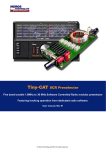
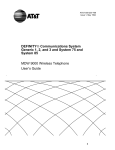
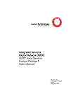
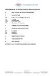
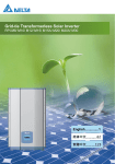
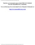
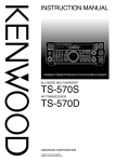
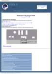
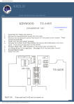
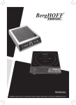
KB2LJJ Radio Mods Database
KB2LJJ
Radio Mods Database and Manuals
Home
Kenwood TS-50 / 50S
www.r6-ru4montesecchieta.it
Scrolling down for all information
IZ5CCV
DBS Speech processor for the Kenwood TS-50
(Speech clipping in the TS-50, RSGB's RadCom June 1997)
INTRODUCTION
For DX work a speech pocessor should be an advantage but the KENWOOD TS-50 does not have one. The
simple speech clipper proposed here does add punch to the signal. It produces more distortion within the pass
band than SSB clipping, but if the microphone gain is not set to high this is inaudible; it causes no platter.
Fig 1
DESCRIPTION
The clipper (Fig 1) consist of a pair of back-to-back 1N4148 diodes in series with a 10 nF DC-blocking capacitor. It is connected between the
collector of Q42 and earth (threaded bushing A1) on the TX-RX UNIT (X57-4220-11). Q42 is the 10.695 MHz double-sideband amplifier
http://www.kb2ljj.com/data/kenwood/ts-50.htm (1 di 14)01/09/2009 0.05.12
KB2LJJ Radio Mods Database
between the balanced modulator and the 2.4 kHz SSB filter. The latter removes intermodulation products of the clipping proces outside the
normal pass band. This clipper also eliminates the tendency of the TS-50 to splatter when speaking into the microphone too loudly.
INSTALLATION
Refer to the manual on page 55.
●
●
●
●
●
●
Remove the lid.
Remove the speaker and its mounting plate.
Unscrew and carefully remove the IF filter PCB.
Locate with figure 1 the clipper connection points on the main PCB and solder, using the threaded bushing A1 as the earth point.
Check the clearance between the clipper components and the filter PCB.
Reassemble.
ADJUSTMENT
●
●
●
●
In CW mode, send a fast string of dots into a dummy load through an analogue SWR/power indicator and note the average meter
deflection.
Swith to menu B nr. 66 "H".
Switch to SSB and speak into the microphone in a normal voice.
Adjust the (yellow) VR7 for an average meter reading just below the one previously noted.
Kenwood TS-50 programming info, COM command
sNotes on communicating with the TS50 - it appears to be the standard Kenwood format that most of their radios use.
Kenwood TS-50 programming info:
Full duplex serial, 4800 Baud, 1 start, 8 data, 2 stop bits No parity, TTL level
Commands consist of a 2-char command, parameters, and a semicolon terminator
Error messages:
?; - Syntax error or radio in wrong mode
E; - Communications error
O; - Processing not complete
FA00007000000; Set VFO A to 7 MHz. Freqs are 11 digits, in Hz
FA;
Read VFO A
FB00007000000; Set VFO B to 7 MHz. Freqs are 11 digits, in Hz
FB;
Read VFO B
FNx;
ID;
Select VFO A (x=0), VFB B (x=1) or MR (x=2)
Read radio ID - TS-50 is 013
IF;
Read info from radio - answer is
IFaaaaaaaaaaa bbbbbc ddefghijkk ;
a: 11 digits of frequnecy. b: RIT offset in Hz - first char is +
or -.
c: 0-rit off, 1-rit on d: memory channel. e: 0-rx, 1-tx f:
mode
g: 0-VFO A, 1-VFO B, 2-MR, h:scan off/on i: split off/on j:
tone off/on
k: ctcss frequency
MDm;
Set mode to m
http://www.kb2ljj.com/data/kenwood/ts-50.htm (2 di 14)01/09/2009 0.05.12
KB2LJJ Radio Mods Database
TX;
RX;
Transmit
Receive
SPa;
Split off (a=0) or on (a=1)
mode: 1 - lsb, 2 - usb, 3 - cw, 4 - fm, 5 - am
CTCSS: 38 standard tones numbered 01 (67.0) - 38 (250.3) or 39 (1750
Hz)
TS-50 Service menu
Factory Adjustments
Hold down NB and MHz keys + Power ON.
Turn the Frequency Tuning knob to change menu number.
A0
A1
A2
A3
A4
A5
A6
A7
A8
A9
AA
AB
AC
AD
Checksum diplay (version of YOUR installed pgm)
RIT center
Initial value 80
IF-Shift center
Initial value 80
LSB carrier point
Initial value
0
USB carrier point
Initial value
0
S-meter adjust S1 (not FM)
Initial value 2E
S-meter adjust S9 (not FM)
Initial value 73
S-meter adjust full (not FM) Initial value C2
S-meter FM start
Initial value 91
S-meter FM full scale
Initial value CC
RF-meter adjust low (10W)
Initial value 3C
RF-meter adjust middle (50W) Initial value 80
RF-meter adjust high (100W) Initial value B1
Write to Eprom by pressing UP or DOWN key.
Kenwood TS-50 to Icom and LDG ATU Interface
TThis article describes the result of my investigations into connecting automatic ATUs to the Kenwood TS-50 HF transceiver. I wanted
to use my TS-50 in a mobile environment, but was irritated by the lack of integration between it and the Icom AH-2 automatic ATU that
I was also planning to use. All of the mode and power switching required to get the automatic ATU to tune seemed to me to be a waste
of effort, and possibly dangerous while driving. There had to be a better way.
I started off by looking on the web for information – but there appeared to be very little out there. On www.mods.dk, my usual first port
of call for these sorts of things, the closest I got was a writeup by DF6KR on TS-50 to AT-50 serial communications – these two boxes
talk using a 4800bps inverted serial communications scheme. Having found this I decided that a small microcontroller could easily
emulate the AT-50 and provide control to a dumber ATU. However, by accident while collecting further information on the serial
protocol I made a wiring error and an interesting discovery.
Dumb Mode
It turns out that the ATU interface on the TS-50 can work in two different modes. As well as the serial interface scheme there is a second
mode. If you link the TS and TT signals on the ACC (ATU) connector then the TS-50 detects this at powerup and goes into this
alternative 'dumb' ATU control mode.
This mode has the following features:
1. The AT TUNE button starts to work. Pressing the AT TUNE button on the rig will temporarily select low power, and key the
transmitter in CW mode. Pressing the button again will cancel this and return the rig to normal operation. If the tune operation is
not cancelled within 30 seconds the TS50 starts beeping at you to remind you that the transmitter is still active. Thus with no
http://www.kb2ljj.com/data/kenwood/ts-50.htm (3 di 14)01/09/2009 0.05.12
KB2LJJ Radio Mods Database
changes other than a loopback wire you can have a single button to perform the necessary transmitting for atu autotuning.
2. While the rig is idle the TS signal sits at 5V. During the AT TUNE operation it drops to 0V, taking TT with it (as they're
looped). You can detect this state change and use it to trigger an ATU tune cycle.
3. If during the ATU tune cycle you break the TS/TT loop for a short period (a few hundred milliseconds) and allow TT to float
high then the AT tune operation ceases, and TS returns to 5V. This will allow a simple circuit to monitor the 'key transmitter'
line from the ATU, and temporarily break the TS/TT loopback when transmitters keying ceases, to end the TS-50 transmit cycle.
Note that (at least on my TS-50) the TS and TT interface signals comprise the centre column of contacts on the ACC connector. TS is on
the bottom, and TT on the top. On one of the mods sites I've seen a different set of pinouts for the ACC connector - this is either wrong
or there's more than one possible wiring setup out there.
Note also that the TS-50 does its 'dumb mode' detection at power up. It brings TS high, then pulses it low for about 120ms. Any 'tune
detect' circuit should thus make sure that TS has stayed low for longer than this before starting the antenna tune cycle.
Interface Circuit
The diagram shows the circuit I used to make the interface to an Icom AH-2 ATU work. The TS/TT loopback is provided by (one
quarter of) a 74HC4066 analog switch device. This device loops back TS to TT whenever the control input on pin 13 is high, which is
most of the time. Note that the control inputs for the unused switches on the 74HC4066 (pins 5, 6 and 12) are grounded.
The top half of the 74HC123 dual monostable is used to deliver a positive pulse of approximately 500ms duration when a negative edge
is sensed on the TS/TT loop, indicating that a tune operation has commenced. This pulse turns on the BC549 transistor, grounding the
TUNE signal and initiating tuning on the ATU.
The bottom half of the 74HC123 is used to detect a positive edge on the KEY signal (on the LDG RT-11 ATU this is called 706-OUT,
probably because the Icom interface uses it) from the ATU, signifying that the ATU has finished keying the transmitter. Upon sensing
this, it delivers a negative pulse of approximately 500ms duration to the switch input of the 74HC4066, breaking the TS/TT loopback for
this period. This tells the rig that tuning is complete.
Power for the interface is provided using a 74L05 miniature 5V regulator, running from the 12V feed from the TS-50 ATU connector.
The resistor and zener on the regulator input are to provide extra protection from ignition spikes in a mobile environment - but may not
be so necessary as the TS-50 has an internal protection diode. Note that I've not included a fuse on the drawing - the TS50 has an
internal 4A fuse on the ATU interface 12V output line - but on reflection putting a low current fuse in the power feed prior to the voltage
regulator is probably a good idea. The circuit itself should draw no more than a few milliamps.
This circuit could probably be improved with better understanding of the TS-50. It's still based on my observation that looping back TS/
TT puts the ATU interface into 'dumb' mode. My initial attempt at a design took a logic interface approach to the TS/TT connection, but
I found that in some circumstances it appeared that TT was also driving the loop, and so this approach didn't work. The use of the
74HC4066 is thus a little bit of laziness - as an analog switch it's the closest thing to a real loop I could easily control, and it stops me
from having to understand the full complexities of the interface. In my original breadboard I used a normal CMOS 4066 rather than the
74HC flavour. It worked fine, but Len (a greybeard hardware engineer friend who kindly reviewed my design) suggested that the 74HC
version has a lower on resistance and will work better with 5V logic levels on the switch input.
My interface works happily with the Icom AH-2 ATU - I believe the AH-3 and AH-4 also have the same interface. The LDG
Electronics RT-11 has an effectively identical interface, too. Note that if the ATU tunes very quickly (< 0.5 second) at times then you
may need to reduce the length of the TUNE pulse, otherwise it may try to tune a second time just as the transmitter turns off. You'd do
this by reducing the values of the resistor and/or the capacitor on pins 14 and 15 of the 74HC123. Pulse duration is about 0.45 times the
product of the resistor and capacitor values.
ACC Connector
You can make an adequate if not beautiful substitute for a real ACC plug on the TS-50 from a broken ATX style (modern) PC power
supply. If you don't have one in your junkbox you may be able to charm one out of your local PC clone shop - mine didn't even charge
me, which may say something about PC power supply reliability! The main connector that goes onto the PC motherboard from these
power supplies is the correct pitch, but has far too many contacts, some of the wrong shape. With some judicious scalpel work you can
reduce the connector to six contacts, and then remove all of the plastic on the three of these that go into the circular holes, leaving only
http://www.kb2ljj.com/data/kenwood/ts-50.htm (4 di 14)01/09/2009 0.05.12
KB2LJJ Radio Mods Database
the pins. This latter part of the process is easiest done with the metal pins removed, which you can do with a fine screwdriver and a bit of
fiddling.
Once you've formed the connector and proved it fits you can then also cut away sufficient of the locking tab that the connector will hold
in place correctly despite being offset by half a pin from its correct location. Of course, if you can find a retailer who'll sell a small
quantity JST brand ELP-06V plugs and associated pins then you have no need of this workaround. I've not been so lucky thus far.
Summary and Disclaimer
With a handful of cheap components it is possible to connect a TS-50 to several different automatic ATUs. This exercise solved a
problem for me – I hope it makes life easier for you too. I’m always interested in feedback on this design – so feel free to get in touch at
the email address above if you have comments.
Please also understand - this article is published in good faith, and I’m using the circuit myself, but in the end the responsibility for any
blown up rigs or ATUs is yours alone. Take care.
TS-50S Australian Extended Tx
http://www.kb2ljj.com/data/kenwood/ts-50.htm (5 di 14)01/09/2009 0.05.12
KB2LJJ Radio Mods Database
Tx mod for TS-50S originally from Sydney, Australia in 1995.
Review the mod where the coloured picture of the control board is provided. This shows a picture of D5. The pads for D1 through D5
are obvious on the control board which is piggy backed on the PLL board with 2 multipin sockets and 2 screws.
This radio only had D4 obvious - snipping it did not do the job. D1, D2 and D3 were not fitted. (D5 not fitted next to D4 - see below)
Disconnect the power.
Ground the radio and keep one hand on the metal work or use a wrist strap to ground yourself. Locate the Control Board as it says in the
Instruction Manual for "Options Installation" and "TCXO UNIT (SO-2)".
Remove the control board as it says in the book.
The 3 plugs are not as such plugs - the catch bar releases the ribbon cable and is easy to push apart but a bit fiddly to get back in. 3 hands
might be needed and you have to push the bar down as well as in. Very little force is needed. Do not force it - if it wont go in then you
have not got the right angle.
The 2 screws required the use of a special tool which was not available. A fine pointed set of side cutter wire snips can be used to tightly
grip the round headed screws by the dimples.
Suggest you locate the 2 white plug/sockets visually by looking under the Control Board before you pull off the Control board from the
PLL board so that you dont bend the pins since it has to go strait up at both ends.
Under the board (under D5) was found what looked like a blob of opaque glue about 4mm diameter. Under this glue could be seen a
black speck. The glue was levered off and a Surface Mount diode came off with it - breaking away from the PCB track. Diode about
1.5*1mm. Obviously this blob was doing the function of D5.
A full "Microprocessor Reset" as it says in the Instruction Book gave the desired result.
Other changes were also successfull.
See instruction manual "MENU SET-UP"
USB below 10MHz - alter Memory location A04 from "SSB" to "ULC".
Double Zero on frequency display - put "85" into memory B70 instead of "82".
Note also the mod in mods.dk which explains what to do if the memory battery is changed or disconnected. On replacement of the
memory battery you have to cycle the radio on and then immediately off otherwise the memory battery drain is 1mA and it will go flat
very quickly.
PS WANTED: Does anyone know of a mod to make the Kenwood TS-50S radio switch on with the Low power option setting set.
Altering Memory A00 to 10 does not do this. The radio switches on in the power setting you last used it in, which is not good for
manual tuning if that happened to be high power.
Kenwood TS-50S Wideband TX & double zero readout
New TS-50S to enable Wideband TX cut D3 &D4 on the digital unit X46 - 315X - XX.
On TS-50S the mod is the same except cut D5 as well to enable.
Enable this mod entirely at your own risk and responsibility.
Note; enabling the double zero mod you will lose the RIT display, it's activation is now indicated by a beep. To reverse enable a partial
reset by holding down A/B and switch on, or, retain the 70/85 key 4 mic setting and normal function will resume at a key press.
TS-50 High-Power-Modification
http://www.kb2ljj.com/data/kenwood/ts-50.htm (6 di 14)01/09/2009 0.05.12
KB2LJJ Radio Mods Database
As the most of you TS-50-Users surely know, it is possible to increase the Medium-Power, the Low-Power but not the High-PowerSetting. Reason: There is no Trim-Pot, it is a small SMD-Resistor. With that small Modification you'll get a Trim-Pot and the TS-50 is
able to run up to 180 W output without any problems.
1. Remove Top-Cover and hook out the internal speaker. Place the rig top up, display to you. The area you need is closed to the left
side of the CW-Filter-Board on the main-RF-Board, where the Filter-Board is screwed on.
On the board is printed on 'PL', 'PM', 'PH' and an arrow. Above are two pots and two little black chips, the right one (SMDResistor) is very closed to the second pot.
2. Remove this SMD-Resistor (R214, 10k), wich is located closed above the two pots for Med and Low. It is a VERY small black
chip, marked with '103'. Be CAREFUL while soldering!!
3. Make yourselfer a small Board, 25 mm long, 8-10 mm wide. At one end drill a centered 3mm-hole closed to the edge of the
board.
4. Solder one conventional 4k7-Resitor (standing, a 5k6 or 6k8 also can do it) and a conventional 10k-Trim-Pot (lying) in serial
order on this board.
Make sure, you make no shorts and build the circuit as narrow as possible and very closed to the reverse end, from where you
drilled the hole in - you later need 10mm space at the drilled end!
5. Connect two two fine wires (length aprox. 20 mm) at the ends of this little circuit and solder it (CAREFULLY!!) to the free
solder-joints of the resistor. To make it a bit easier: the right one you can solder to a joint about 4mm away of it - just follow the
small trace to the right and you will find this lonesome contact.
6. Remove the screw of the CW-Filter-Board, place your little board hole-on-hole on top of the Filter-Board and Re-Screw the two
boards together to the main-board. So your little "Tuning-Unit" is fixed, hanging above the Med- and Low-pot.
7. Connect the rig to a power-supply (25-30 Amps!), a power-meter, a dummy-load and switch it on. No smoke? So you might
have done everything all right ;-)
8. Push a FM-Carrier on 14Mhz and set the 'new' pot on the desired output. My TS-50 can do max 185 Watts but I have adjustet it
to 150-160, so it modulates fine 130 Watts SSB with the original mike - what a difference to that 70 before... Don't adjust it to
high, think about your finals and filters!
http://www.kb2ljj.com/data/kenwood/ts-50.htm (7 di 14)01/09/2009 0.05.12
KB2LJJ Radio Mods Database
Thanks to Jim Duarte for this photo.
Note: You are making this Mod on your own risk, I am NOT responsible!
TX 0-30 MHz for the new TS-50
ON the new version are 4 diode on de board.
Cut remove all, D1 D3 D4 D5
Then RESET the Kenwood TS-50
TS-50 Modification Full time "Double-Zero"
http://www.kb2ljj.com/data/kenwood/ts-50.htm (8 di 14)01/09/2009 0.05.12
KB2LJJ Radio Mods Database
This modification makes the "double zero" display full time.)
1. Turn on radio
Go to MENU 'B', item #70.
Program [85] into item 70. This puts the 'double-zero' on the #4 (PF4) button on the microphone. Press the F-LOCK to get out of
the menu function.
Press 'F-LOCK' [ON].
Press and hold PF4 button on mic.
While holding PF4 button down on the mic, press and hold the [SPLIT] button.
Release the PF4 button -then- release the SPLIT button.
Turn F-LOCK [off].
Go back to MENU 'B', item '70', and remove [85] or change the number.
TS-50S "Hello" displayed during TX
Symptom:
Occasionally an "Hello" message will appear in the display of the transceiver when the TS-50S is loaded into a antenna without the use
of an antenna tuner. This symptom usually occurs when the negative terminal of the power supply is floating (un-grounded for RF). This
can result in RF feedback that causes the supply voltage to exceed to 16 Vdc.
Corrective action:
1. Cut the Final Unit PC Board foil in two places, as shown below.
Add a .01 µF chip capacitor (C125) as shown below.
Add a 10 µH chip Ferri-inductor (L102) as shown below.
Add an insulated jumper wire as shown below.
Parts required:
Qty Description
1 .1 µF chip capacitor
1 10 µH Ferri-inductor
Kenwood Part No. Circuit description
CK73EB1E104K C125
L40-1001-48
L102
Caution: This modification requires soldering equipment rated for CMOS type circuits. It also requires familiarity with surface mount
soldering techniques. If you do not have the proper equipment or knowledge do not attempt this modification yourself. Seek qualified
assistance.
TS-50S Mechanical noise from final unit
http://www.kb2ljj.com/data/kenwood/ts-50.htm (9 di 14)01/09/2009 0.05.12
KB2LJJ Radio Mods Database
When the transceiver is subjected to vibration a mechanical noise can be heard from the output transformer area. This has led to concern
by several consumers that something is loose or improperly installed.
Corrective Action:
In order to ease consumer concern toy should add a cushion under transformer L4 as shown in the accompanying diagram, and replace
transformer L13 at the same time. This transformer has been fastened to the circuit board with high temperature adhesive, so use caution
when removing it from the circuit board.
Parts required:
Qty Description
Old part No. New Part No Circuit Description
1 Cushion
NA
G13-0871-04 (Under L4)
1 Output transformer
L39-1209-25 L39-1252-05 L13
TS-50S Lithium battery replacement notes
Service Bulletin no. 1015 (10 May 1993)
Procedure:
Immediately after replacing the Lithium battery you must cycle the radio ON then OFF. Failure to follow this procedure will result in
premature failure of the battery. If the power is not cycled ON then OFF the microprocessor will immediately begin drawing
approximately 1 mA of power from the Lithium battery, resulting in poor battery life.
When the battery is replaced we recommend the insulation sheet also be changed. Part numbers for the battery and insulation sheet
follow.
Parts required:
Qty Description
1 Lithium battery
1 Insulating sheet
Kenwood Part No. Circuit description
W09-0515-05
BA1
F20-0521-04
--
Caution: This modification requires soldering equipment rated for CMOS type circuits. It also requires familiarity with surface mount
soldering techniques. If you do not have the proper equipment or knowledge do not attempt this modification yourself. Seek qualified
assistance.
TS50 TS-60 FIX: LCD display dark
Problems:
No display illumination, LEDs On Air, AT TUNE no function The menu item 2 has no effect, display keeps always dark.
All other functions normal.
Possible reason:
Bad contact LCD Assy for 5V line to R9, R10 and IC5.
Power on the TS50 and check voltage at R9/R10.
If voltage is 0V, but display readout is active, the reason might be as discribed.
Measurement to fix it:
Look for the small hole near R9 at the LCD Assy, component side view, where the contact between the two sides of the LCD Assy is located.
http://www.kb2ljj.com/data/kenwood/ts-50.htm (10 di 14)01/09/2009 0.05.12
KB2LJJ Radio Mods Database
If you have no service manual:
This is the side oriented to the front side of the device.
R9/R10 are located close to the two LEDs.
Take a small size needle to pick through the contact hole to encrease the diameter.
Make a contact between the two layers by soldering a piece of wire across the hole.
Check the 5V at R9/R10.
TS50<-->AT50 communication
+-------------------------------------------------+
¦
TS-50 <--> AT-50
Communication
¦
+-------------------------------------------------¦
¦
as measured/discovered by DF6KR
¦
¦
No guarantee for whatsoever....
¦
+-------------------------------------------------+
Communication method:
Tranfer rate:
Synchronization:
Parity:
Signal format:
Serial interface
4800 bps
Start-stop (Asynchronous)
None
TTL level (!)
+---+
+-------------------+
¦
+---+
¦
1:
Ground
http://www.kb2ljj.com/data/kenwood/ts-50.htm (11 di 14)01/09/2009 0.05.12
KB2LJJ Radio Mods Database
¦
ACC
1
¦ 2 ¦
3
¦
¦ +---+ +---+ +---+ ¦
¦ ¦ 4 ¦
5
¦ 6 ¦ ¦
¦ +---+
+---+ ¦
+-------------------+
Rear Panel Connector ACC
2:
TT (TS50<--AT50)TTL!
3:
4:
5:
6:
TS (TS50-->AT50)TTL!
N.C.
ATG (signal ground)
+13.8V from TS50
Timing:
1. at Power-on:
===============
+------------------+ ++1
++3++6
TT--+
+---------------------->
|
| |
| |
|
1.45 sec---+ |
| |
+--+
++2
+-+4,5
TS--+ +--------------------------------------->
|
|<- 600ms->|
0 + 90ms
resume time
t
Signal:
1
3
6
TT: ;;;;;0C;___0D01;__________0F11;
2
4
5
TS: ________0C;_____0D01;0F11;____
1:
2:
3:
4:
5:
6:
Power on comm.
Power on answer
Auto on request
Auto resume finished
ok at50
ok answer ts50
2. DOWN-UP-Communication
========================
TT: 0E02;__________0F11;__
TS: _____0E02;0F11;_______
same:
0E04;0E04;0F11;0F11;
0E05;0E05;0F11;0F11;
0E06;0E06;0F11;0F11;
0E07;0E07;0F11;0F11;
0E08;0E08;0F11;0F11;
0E09;0E09;0F11;0F11;
0E0B;0E0B;0F11;0F11;
0E0C;0E0C;0F11;0F11;
0E01;0E01;0F11;0F11;
UP
UP
UP
UP
UP
UP
UP
UP
UP
- UP from 1.8 to 3.5
3.5 -->
7
-->
10 -->
14 -->
18 -->
21 -->
24.5-->
28 -->
29 -->
7
10
14
18
21
24.5
28
29
1.8
DOWNs
0E0C;0E0C;0F11;0F11;
0E0B;0E0B;0F11;0F11;
.
.
0E01;0E01;0F11;0F11;
TUNE:
AUTO OFF (THRU):
AUTO ON:
tune error:
0D03;0D03;0F41;0F41;
0D00;0D00;
0D01;0D01;
0d03;0d03;0F83;0F83;
http://www.kb2ljj.com/data/kenwood/ts-50.htm (12 di 14)01/09/2009 0.05.12
KB2LJJ Radio Mods Database
TX Coverage mod TS-50
just got a spanking new Kenwood TS-50S.
Searching around the local LLBBS's I found a very simple mod for full transmit from 1.7 - 30 mhz....
Remove the bottom cover of the TS-50
Locate the PLL board -- it is the pc board on top of the main board, it has a shield on it's right side.
Locate the only non-surface mounted component on the PLL board -- look near the rear left-hand side of the pll board (front of radio
facing you) and remove the very obvious diode. You can't miss, ther's only one.
Replace cover.
TS-50 S RF Gain
COLOC
http://www.kb2ljj.com/data/kenwood/ts-50.htm (13 di 14)01/09/2009 0.05.12
Portuguese Language
KB2LJJ Radio Mods Database
O
Remember it is Illegal to transmit out of band. This Modification is for Informational purposes ONLY.
Doing such modifications on your radio may void any warranty and damage your equipment.
All mods found on this database are offered to me by other amateur radio hams or captured by Packet system.
KB2LJJ take no responsibility or liability for any damage done resulting from any modification.
http://www.kb2ljj.com/data/kenwood/ts-50.htm (14 di 14)01/09/2009 0.05.12